1
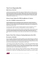
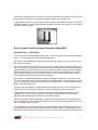
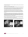
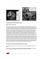
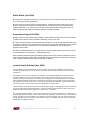
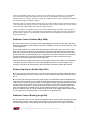
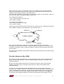
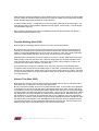
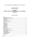
Tips from Comanche Flyer magazines Feb 2002 – Aug 2009
CHAPTER EIGHT
AIRFRAME
Table of Contents
Flight Control Rigging May 2004)..........................................................................2
Aileron Control Cables (Oct 2002) (fromMaurice’s Toolbox).................................2
Replace Clevis Pins to Preserve Cowling Attachments (Dec 2003)......................2
Xenon Lights Provide Serious Illumination (May 2005).........................................3
Paint Stripper Problems (Dec2002) ......................................................................5
Gluing Door Seals with Weatherstrip (Jan 2004) ..................................................5
Static Wicks (Jan 2004) ........................................................................................6
Asymmetric flaps (Feb 2004) ................................................................................6
Janitrol Heater Problem (Apr 2004) ......................................................................6
Stabilator Control Problem (May 2004).................................................................7
Rubber Gap Seal on Rudder May 2004)...............................................................7
Stabilator Control Binding (Aug 2004)...................................................................7
Comanche 260C – Engine Mount Dilemma (Oct 2004) ........................................8
Shoulder Harnesses (Nov 2004)...........................................................................9
Electric Trim (Feb 2005) .....................................................................................10
Throttle Sticking (Nov 2005) ...............................................................................11
Aileron Trim (Nov 2005)......................................................................................11
Upgrading Supplemental Oxygen Will Lighten Your Load (Sep 2006)................12
Copyright © 2009, International Comanche Society, Inc. All rights reserved.
Flight Control Rigging May 2004)
Mike Rohrer ICS #13393
Another item that should be looked at is the rigging on the flight controls. How many of you out
there are flying with the aileron trim tab bent straight up? How about the control cable tensions?
When was the last time these were checked? I would bet that a lot of Comanches haven’t been
rigged nor had the tension checked since new. It isn’t a big job, and the tools are easy to make.
All the required tools and how to manufacture them are in the Manual. It is amazing the speed
increase when everything is in rig.
Aileron Control Cables (Oct 2002) (fromMaurice’s Toolbox)
Jerry Irvin, ICS #02241, past president of ICS
The author called to say that on inspecting one of his Comanches he found that the aileron
balance cables had cut their way through the phenolic guide block in the wings. Please see the
pictures, and note the position of the cables. When these pictures were taken the cable tension
was 23 lbs. As I have mentioned in the FLYER before the cable tension in our Comanches is not
getting checked often enough.
The control system drawing for Jerry's Comanche is #21553. It covers 180 & 250's - (s/n 103
through 2843 & for 180's - s/n 2844 up). Drawing #23029 is for 250's (s/n #2844 & up).
The pictures are of Jerry's 180 (s/n 2219); however he checked another 180 s/n 1939 and found
it to be OK. He also checked a 250 (s/n 3470) and found it with the same problem as his. It's my
strong advice that all Comanche owners have their control cables checked for condition and
proper alignment. Also checking for proper tension will make it easier for you and the autopilot to
fly.
Replace Clevis Pins to Preserve Cowling Attachments (Dec 2003)
Ben Ayalon, ICS #14048
One of the design advantages of the single Comanche is the minimal effort that is required to
open the cowling and inspect the engine. However, this feature is also a weakness point. Think
about it. How many times have you opened and closed the cowling during pre-flight? How many
times did your mechanics do the same when they were working on your aircraft? Have you ever
spent a second thought regarding the cowling latches and the hinges?
I am sure that you did not; neither did my mechanic or I. It was in April, a month after the annual,
when I pre-flighted the aircraft before a short local flight. As you have guessed, one of the cowling
latches fell off and remained in my hand. A closer look revealed that the hinge (a clevis pin) was
corroded and worn around the contact points with the latch. I thought to myself, "If one is so bad
what about the others? It would be sensible to replace them all."
Two days later a new set of clevis pins arrived. Not thinking too much, I walked to the grinding
machine as the pin heads need grinding to allow them to go into position. In my haste I did not
pay attention to a "small" point. The heads should be ground in one way only. Of course, I did not
Copyright © 2009, International Comanche Society, Inc. All rights reserved.
2
think about it, so some pins have lost the wrong part of their head. Pay attention when you grind
the heads. You must grind it in parallel to the split pin that goes in the other end.
In the attached picture you can see one of the pins that were removed. All were in the same
condition. Replace or at least inspect these pins before you lose your latches or your cowling
becomes loose during flight.
Xenon Lights Provide Serious Illumination (May 2005)
Andrew Foster - ICS #14236
I am not going to buy those thousand dollar lights … I am not going to buy those thousand dollar
lights … I am not going to buy those thousand dollar lights.”
Then how on earth did this box with Knots2U printed all over it arrive at my door? Honey, where
did that box come from?
Ours is a 1961 PA 24 250, that I have had the privilege of owning and of course maintaining, with
the help of a partner, for the last five years. Like most Comanche owners we take great pride in a
fabulous machine. We, like all of you, have had numerous projects updating a 40-year-old jewel. I
think to truly appreciate any airplane a certain amount of time has to be spent “fixing” it. Without
the ICS, Webco, Ron and John’s Comanche service, and all the other valuable resources we
have, keeping these planes flying would be very difficult.
Most recently, I installed Knots2U Xenon Lights and thought I would share my experience with
you. Their Web site can offer you the specific technical data but there are some high points for us
layman. The HID lights draw only 2.5 amps apiece compared to the 7 amps for the GE. The bulb
life is an incredible 5,000 hours.
They do have a nice warranty – lifetime (which will be longer than I am around), as long as you
own the plane. The warranty does drop to five years if the plane is sold after installation.
The HID lights for the Comanche come pre-mounted in a bracket that will fit exactly into your
existing holes, very nice. They can be left on during all phases of flight. If you burn one out,
KNOTS2U will replace it for free as long as you own the airplane.
The lights cost $550 a piece, plus shipping. They are FAA-PMA approved, and Knots2U has an
STC for installation in all the Comanche models. And, of course, the best thing about them is how
they look: bright, bright, and bright.
It was explained to me that the light is truer to normal sunlight through an excited Xenon gas. The
end result is that these lights put out some serious illumination, which I can always use more of.
Illumination that is. However, it is excellent to see so much more on the ground at night and of the
Copyright © 2009, International Comanche Society, Inc. All rights reserved.
3
runway environment on approach for landing. The difference is startling. And they look really cool
too, always a bonus feature.
Installation can be performed by any AP. It is fairly straightforward. Here’s the basic summary, but
always defer to your AP for any installation issues.
Remove the wing tips to expose the landing light area. Be careful pulling out the Plexiglas lens as
mine was a little brittle from age. The four screws holding the existing bracket all have a nut on
the back. Remove them and install the new bracket/HID light combination. Screws and lock nuts
are not provided, but 6-32 SS machine screws, with locking nuts worked fine for this.
Next the ballast should be attached to the outer wing rib. A small point here. The wing rib is
formed and not flat. We had to make a small spacer in order to properly mount the ballast. We
used a simple aluminum tube, cut to length, around the mounting bolts, and that worked very
well. I don’t know the exact bolt size or length. Again, you will need to supply your own bolts and
nuts for this.
The existing positive and ground are then connected to the ballast. I was told knife connectors
are best, but we used male/female type connectors. Knots2U told me you should make sure the
harness between the ballast and the light are firmly pressed into place to make sure you have an
established contact. Don’t worry should you get the positive and negative reversed, it will not
damage the lights. But they will not work. Simply correct the mistake. I managed not to make that
one. Knots2U explained that one to me before installation.
Make sure your wiring is secured properly, test the light, and then put the lens and wingtip back
on. Voila! The installation took about three hours total for both sides. The hardest part is waiting
for night to see how they actually look. You will be blown away.
I hope this information has been helpful. Knots2U was very thorough in explaining any installation
issues, and their customer support was great. Best of luck to Comanche owners and flyers!
Copyright © 2009, International Comanche Society, Inc. All rights reserved.
4
Paint Stripper Problems (Dec2002)
Mike Rohrer ICS #13392
I need to cover another area concerning the article about paint stripper getting into the torque
tube area and causing corrosion. Some of you have been made to believe that unless your plane
has recently received a new paint job, you don't have a problem. I assure you that this is far from
the truth. It's a fact that paint stripper has been a problem, but be assured that this isn't the only
thing that causes corrosion on the torque tubes and attachment bolts. This brings me to this
month's item. I just finished an Annual Inspection on a very nice PA24-260 with a new paint job
(less than 2 years). As always, we pulled the Stabilator off and found that the bearings were
ruined because paint stripper had found its way into the bearings. Also found was a severe
corrosion problem. I have a suggestion when it comes to getting your airplane painted, and so far
it has worked. The first thing you need to do is remove all the panels that are required to be
removed for the annual inspection. If you don't know which to remove, ask your technician, and if
he doesn't know, call me. The maintenance manual has a picture of panels to be removed. The
paint shop can paint these panels off the airplane. I suggest removing these panels so that when
it comes time to inspect your airplane, the technician doesn't ruin the finish when he/she removes
the screw and panels. I use stainless hardware when I install the panels, and it makes for a nice
looking airplane. This includes painting the cowling off the airplane as well. I suggest painting the
inside of the cowling white as it makes it easy to see the engine compartment and helps to see oil
leaks. Now back to the bearings. The big problem is that the bearings do not get covered, and in
time fail, due to the stripper. This includes the wheel bearings and races. Great care should go
into paint preparation. This can save you lots of money and grief down the road.
Gluing Door Seals with Weatherstrip (Jan 2004)
Q I am installing a new door seal on my Comanche and am wondering what to use to glue it in
place?
A The product I recommend is 3M Super Weatherstrip Adhesive. 3M Part #8001. It is available
from Aircraft Spruce for $5.90 for a 5 oz. tube. The A/C Spruce p/n is 09-2700.
Copyright © 2009, International Comanche Society, Inc. All rights reserved.
5
Static Wicks (Jan 2004)
Q I would like to put static wicks on my PA-30. Any info you can supply on field approvals (337’s)
or an STC will be greatly appreciated.
A In the Piper PA-30 parts manual, refer to figure 54. It shows where the static wicks can be
located. The Piper part number for the static wicks is p/n 494-678. Since it is listed as factory
optional equipment, in our opinion a 337 or STC would not be needed. A logbook entry by an
A&P with appropriate weight and balance changes is all that is needed.
Asymmetric flaps (Feb 2004)
Q What causes the asymmetrical flap condition? I just experienced such an occurrence, but have
no idea what caused it. When I landed the stuck flap went up on its own.
A A worn or dirty flap track can cause the flap on that side to not retract fully after extension. This
is because the flaps on all Comanches are retracted via a spring and cable arrangement, which is
separate for each flap. The result can be an asymmetric flap situation, which will cause a
significant roll moment.
On twins it sometimes fees like an engine failure. It is for this reason that touch-and-go’s are not
recommended in our Comanche’s – particularly the twins.
Early model aircraft with hinged (manual) flaps still have the spring retract mechanism but do not
have tracks to get dirty or bind. When you landed, it simply jarred the stuck flap loose. Inspect for
wear, and clean the flap tracks and lubricate with dry silicone.
Janitrol Heater Problem (Apr 2004)
The following is not in the traditional Q and A format, but rather an explanation by European
member David Buttle as to how he solved a problem with his Janitrol heater in his PA-39 Twin
Comanche.
The heater would not work except at low altitude. I checked the heater out on the ground and
found that it did not work on the ground but does in the air at low altitude. The cause of it not
working was that the combustion air switch was not triggering on the combustion air. I naturally
then suspected that the combustion air blower was not giving enough flow since this is the only
part that was not renewed last year. I brought the blower home and tested it on the heater that I
removed last year. The pressure switch in it did detect the airflow okay.
I therefore dug out the service manual and connected a length of clear plastic pipe into the airflow
as per the manual and with a little water in the tube measured the pressure. It was 1.25 inches
where the manual says that it should be a minimum of 1.5 inches.
On the other hand the voltage I was using for the blower motor was only about 11.5 volts from a
small sealed lead acid battery. I then went back to the plane and removed the new combustion air
switch, brought it home and tested it. I found that it would not trigger until 1.25 inches instead of
the specification 0.4 to 0.6 inches. I think that the case of the pressure switch may have become
distorted in me shipping it home.
Copyright © 2009, International Comanche Society, Inc. All rights reserved.
6
There is an adjusting screw on it so I reset it to 0.5 inches as per the manual. On re-installation,
all now works fine. What was happening is that ram air at low altitudes was bringing the air
pressure above 1.25 inches, but was not doing so at altitude until I put the nose down and started
the descent at higher indicated airspeed.
Obviously if the air pressure switch requires only 0.5 inches of water pressure and the pressure is
1.25 inches with low supply volts and no airspeed then there is plenty in hand when in the air with
ram air and with higher supply volts with the engines fired up.
I have found that it is relatively easy to remove the pressure switch and test it using a length of
plastic tube and some water. I generated the test pressure by raising the free end of the tube so
that the water is forced to run toward the pressure switch, thus pressuring the line between the
water and the switch
Stabilator Control Problem (May 2004)
Q I heard a story about a Comanche in the United Kingdom that crashed a few years ago due to
a mechanical malfunction that resulted in the loss of stabilator control. Is this true? And if so, what
exactly happened?
A The airplane was a Twin Comanche that belonged to member Ron Nunn. Ron was on a test
flight with his mechanic when the aircraft suddenly pitched up and began shaking violently. By
pulling off power and both pushing forward on the yoke with hands and knees, they were able to
get the nose down. They landed gear up in a rough field. Ron and his mechanic survived but the
aircraft was destroyed. It was discovered that the stabilator trim tab arm bolt and nut were
missing. The aircraft had just had its annual inspection.
That bolt has become widely referred to by the European Tribe as “Ron’s Bolt,” and confirmation
of the bolts’ presence has become a part of the preflight inspection by most European Tribe
members. It would not be a bad idea for all ICS members to add Ron’s Bolt to the checklist.
Rubber Gap Seal on Rudder May 2004)
Q At a recent fly-in I noticed that many of the Twin Comanches have a rubber seal at the front of
the rudder while others do not. Is there a reason some Comanches have these seals and others
don’t?
A The rubber gap seal was produced by Piper as part of an aftermarket “airflow modification kit.”
After there were a number of Vmc accidents, Piper determined that there was a significant loss of
rudder authority at slow airspeed because of air leakage through the gap between the vertical tail
and the rudder. Some aircraft have not had the kit installed, or the rubber has deteriorated and
has been removed. Knots 2 U produces an aluminum gap seal that can be easily installed and
looks a lot better than the rubber seal. It can be installed on singles or Twin Comanches. The
reason to install the seal on a single, besides the good looks, is the added rudder authority which
can be useful when performing a slip or recovering from unusual attitudes.
Stabilator Control Binding (Aug 2004)
Q I have a problem with my Twin Comanche stabilator that so far hasn’t been anything more than
just annoying. However, I feel anything that affects the smooth maneuvering of this beautiful
machine in flight needs to be looked at. When I apply light pressure on the yoke to nose down,
Copyright © 2009, International Comanche Society, Inc. All rights reserved.
7
this results in little or no reaction. Increased pressure over a short period will give a pitch change,
but more than is needed. This required pressure increases with speed. It feels as if the elevator
or pitch servo tab is binding, although a close inspection by an IA of the entire system up to the
point of dismantling the elevator column, hasn’t provided any clues. While manipulating the
control throughout its range on the ground, there is a suggestion of a bind at or near the midpoint
of travel. I wanted to hear your thoughts before we go any further.
A This is a problem that can occur with any Comanche in our fleet, not just the twin, since the
control systems are all basically the same. The symptoms you mention are similar to those others
have experienced. However, it may feel more severe in the twin because of the additional weight
of the aircraft and the heavier “feel” of the controls.
One member described it as “a distinct ‘double motion’ in the pitch control. A little push/pull was
met by resistance that was overcome by force that ‘freed’ the control. Then the cycle would
repeat. It was especially annoying on landing.” Another advises he has seen a problem like this,
which turned out to be the pitch servo drum binding on its shaft when the autopilot was
disengaged. To troubleshoot, he suggests unhooking the servo bridle cable for an inspection.
Other causes can be improper tension or lack of lubrication in the control cables and pulleys or a
worn trim jack. It is a condition that needs to be corrected, but the cause should not be too difficult
to pinpoint with a thorough inspection.
Comanche 260C – Engine Mount Dilemma (Oct 2004)
Q I’m in a quandary. My 260C is grounded because of an intolerable wait for parts to complete
some engine work. New engine mounts are needed and I’ve been told there would be at least a
six-month wait for delivery. What I need are four dynafocal mounting kits, p/n J-3804-30,
according to Lord Manufacturing Company specifications. I’m in Europe and anxious to get my
airplane back in the air. Can you help?
A The Lord mount kit for the long nose Comanche 260C installation seems impossible to get.
With relatively few 260Cs in the fleet, it is a unique application and is the only airplane requiring
that kit. As a result, Lord does not presently stock it. While it may be months before another run is
produced, do not despair. Thanks to the efforts of a resourceful U. S. member who contacted
Lord, there is a way to get the parts you need without delay.
The dynafocal installation for your Lycoming IO- 540N1A5 engine, as it turns out, shares
components used in other kits. The J-3804-30 mounting kit, which is presently unavailable, has
only three essential components:
• One J-3049-34 sandwich mounting;
• One J-3049-35 sandwich mounting; and
• One Y-6769-1-S spacer.
So, for your installation, you need a total of four each of those items. Here’s how you can get
them:
Buy two J-3804-20 and two J-3804-41 mounting kits.
The J-3804-20 kits are for 250 and 260 model Comanches, 1958 though 1969, and are readily
available.
However, the J-3802-41 kit may have to be special ordered since it is also for a rare installation
and only used on aircraft with a three-blade McCauley propeller conversion. This kit is available
from Cessna, which has a strong corporate connection with McCauley Propeller Systems, since
Copyright © 2009, International Comanche Society, Inc. All rights reserved.
8
both are owned by Textron. Our sleuthing expert, who is rebuilding and modernizing a 260C,
found that Cessna keeps these mounts in inventory for shops that do the STC conversion. He
ordered his from Piedmont Aviation Component Services,
http://www.piedmontaviation.com/parts.html, and said Chuck Johnson, parts manager, (336) 776
6140, was very helpful in finding theJ-3802-41 kits for him.
The J-3804-20 kit consists of:
• Two J-3049-35 sandwich mountings; and
• One Y-6769-1-S spacer
The J-3804-41 kit consists of:
• Two J-3049-34 sandwich mountings;
• One Y-6769-1-S spacer
Take the parts from these kits, which are the same as you’d have in four J-3049-30 kits, and have
them installed according to Lord specifications, per the sketch below.
Note: There are differences in stiffness in the rubber compounds used in the sandwich
mountings, so it is important to place the J-3049-35 sandwich mountings only in the top forward
and bottom aft locations, and the J-3049-34 sandwich mountings only in the bottom forward and
top aft locations.
Do it right and your logbook can be signed off using part numbers rather than kit numbers to keep
everything legal.
Shoulder Harnesses (Nov 2004)
Q I just bought a 1960 Comanche 250. I was surprised when I did the pre-buy inspection that it
doesn’t have shoulder harnesses. Is there something available from Piper or are there some
aftermarket options?
A Piper never had shoulder harnesses for the Comanche during the years it was produced.
However, that doesn’t mean you shouldn’t have them now, and we are fortunate to have
aftermarket options.
In 1984, a shoulder harness kit had been designed and an STC was issued to Kosola and
Associates, Inc., located in Albany, Ga. They have a front and rear seat option, and the front seat
option is available with an inertia reel. You can find their advertisement in the Comanche Flyer,
and you can call them toll-free at 800- 4KOSOLA (456-7652) or e-mail them at: [email protected].
In early 1995, Piper designed shoulder harness kits and prepared a service bulletin, No. 980,
Copyright © 2009, International Comanche Society, Inc. All rights reserved.
9
showing kits for all Comanche models Piper considered compliance mandatory, but the kits were
not available. A lead time of 28 weeks was indicated, and it’s possible that no kits were ever
produced. The prices quoted were $873.17 for front seats in the PA-24-180/250, and $894.78 for
the PA-260, PA-24-400 and PA-30. The price for the 3rd and 4th seat kits was $404.80. We don’t
know of any Piper kits that were ever installed.
In 1999, a simpler and less complex kit for front seat shoulder harnesses was designed and an
STC was issued to North Platte Aero. Lenny Spall, ICS member and owner of a 1958 Comanche
250, had designed the kit with a partner and later bought the STC in the name of his company,
PV Aero. A rear seat kit was added about a year later. Prices are $450 for either the front seat or
the back seat kit. If both kits are purchased together, the total price is $800. Lenny can be
reached at (816) 210-4829, or by e-mail at: [email protected].
From our experience, the Kosola kit is a bit more complex, takes longer to install, and requires
opening the headliner. It also requires several rivets through the upper skin of the fuselage to
complete the installation. In the photo, 10 rivets for the Kosola kit have been added to the top
quarter of the fuselage above the back of the right front seat. The rivet pattern is such that it
almost looks like an original installation.
The PV Aero kit leaves the headliner intact and takes less time to install. The kit includes a No.
10 AN bolt that penetrates the fuselage. Some members may object to the appearance of the bolt
head, but others don’t find it distracting since it is a low profile saucer head only about twice the
diameter of existing rivet heads. There is no inertia reel available, but many users prefer the
straight, adjustable harness.
Electric Trim (Feb 2005)
Q I am experiencing problems with the electric trim on my 260B. It works sometimes, but not
always. It is rather random, working in the nose-up direction but not in nose-down. Other times it
works the opposite: no nose-up, but good in nose down. Then other times it will not go either
direction. What’s going on?
A I will assume it is the standard Piper elevator trim system and not an aftermarket/or part of an
autopilot installation. There are a number of reasons the electric trim will act this way:
1: The switch is malfunctioning – The switch reverses the polarity on the two terminals at the trim
unit, which changes the direction of the trim unit motor. To check for proper switch operation,
connect a volt meter across the two connections at the trim unit and operate the switch. The
voltage will go from a plus @1 2 vdc to a minus @ 12vdc when the switch is positioned nose up
then nose down. It is possible for the contacts in the switch itself to be bad or dirty, giving you that
random operation.
2. The trim unit is failing – Usually the motor and drive mechanism in these units are pretty tough
and don’t fail. When they do fail, they don’t do it randomly. So I don’t think this is your problem.
3. The clutch material is worn out or contaminated with lubricant – At one time the wear material
was available from Piper. Very often (these days) the clutch material has gotten contaminated
with ACF50 or CorrosionX or a similar chemical that is applied to protect the airframe. This
causes the trim unit clutch to “slip” under a load, causing the unit to work at random.
Listen for the motor to operate while watching the trim handle for movement. Motor operation
without trim handle movement is a good indication of clutch slippage. If this happens it is
sometimes possible to clean the clutch material with a “brake cleaner” product available from
most auto parts stores. If the unit requires new clutch material, you’ll need to call your favorite
Copyright © 2009, International Comanche Society, Inc. All rights reserved.
10
A&P because it will require taking the control cables loose to remove the unit for the repair. Make
sure the cables get “blocked” before loosening to prevent the cables from coming off the forward
and/or aft cable drums (that will make for a very bad day).
4. Other possible causes: – Cable tension is incorrect (making the load on the motor high) – Aft
cable drum/bushings not lubricated or adjusted correctly (again, a motor load) – Trim tab hinges
not lubricated or are worn
Many of these suggestions may apply to installations other than the stock Piper trim system. I
hope these things are helpful for you.
Throttle Sticking (Nov 2005)
Q My throttle is increasingly difficult to move. How can I correct this problem?
A The secret is to figure out how to get some lube into it. My best method is to disconnect the
cable at the carb/fuel control, pull it through the maze until it’s fairly free and stick it straight up.
Safety it, so that the MAXIMUM portion of the cable is pointed up. Then use a good penetrating
lube such as Mouse Milk and drip it, drop by drop, into the free end of the cable.
While doing this, intermittently (or have a helper) try to move it. Usually, it will start moving more
easily quickly, but at this point don’t stop. Continue dripping the lube and don’t hesitate to let it
soak overnight. When you’re happy, reconnect it and go flying. This procedure is a pain to do
properly but it nearly always will work, and work well.
Having said all this, sometimes it will NOT work. Only once, however, have I actually had to
change the cable out because it was totally frozen. In that case, I pulled the frozen one out and
threw it into my solvent tank. Guess what? The next morning it was “loose as a goose.” The point
is simply that they MUST be properly lubricated to work as they should. Properly lubed, they’ll go
for a very long time.
Aileron Trim (Nov 2005)
Q My airplane constantly requires aileron input to fly straight and level and my left aileron tab is
bent all the way up. What can I do to get more aileron trim?
A This is a frequent problem of some of our older birds that have, in most cases, been damaged
in accidents over the years. Flap and aileron adjustments simply don’t work. The best way to fix
this problem is to first, zero out all flap and aileron adjustments. Clamp the wheel into the straight
and level position and adjust the ailerons for level flight. Then have your A&P fabricate an aileron
trim tab like the one on the left aileron and install it on the RIGHT aileron. Reduce the trim from
the left aileron to no more than 35 to 40 degrees with 10 to 15 degrees on the new right aileron
tab and go fly. It’ll take a couple of flights to get it properly adjusted. Remember that the tab “flies”
the aileron and not the airplane. Also, NEVER bend a tab more than about 40 degrees because
at Comanche speeds, it is aerodynamically stalled if bent more than that. Be sure to have your
A&P/IA properly inspect and authorize the minor mod in the aircraft log.
Copyright © 2009, International Comanche Society, Inc. All rights reserved.
11
Upgrading Supplemental Oxygen Will Lighten Your Load (Sep 2006)
Chris Burns, ICS #9680
For thirteen years I hauled around a 35- pound oxygen bottle attached to my PA-30. As my family
grew, I increasingly looked for ways to cut empty weight so that I could haul the additional
payload without sacrificing fuel. Lightweight starters and alternators helped nip away at the empty
weight. So did a huge box of excess wiring that I removed during a panel modification. When my
son invited his 180-pound roommate for our 2003 Thanksgiving trip to the Bahamas, I looked at
the large green steel cylinder behind the baggage compartment and decided it had to go.
Figure 1:
Nelson A-4 Flow Meter
Give up my oxygen? This seemed like the simplest solution – and the cheapest. Most of my
flights are flown between 8,000 and 11,000 feet – not exactly nosebleed territory. But over the
years, using supplemental oxygen has reduced my fatigue at the end of a full day of flying and
has helped me feel better the next day. I also consider supplemental oxygen an essential for
night flying. I determined giving up supplemental oxygen was not an acceptable answer. I
considered a portable seat-back bottle but decided against it because a built-in system is totally
out of the way until it is needed and then it is always available – even if you were not planning on
needing oxygen. So, rather than chuck the built-in oxygen capability altogether, the search was
on for a lighter built-in oxygen supply that would provide adequate support for my type of flying.
Oxygen supply and delivery has changed since the birth of the Comanche. Oxygen cylinders
have evolved from the need for thick-walled containers to lightweight aluminum containers
wrapped with high-strength carbon fibers. Flow rates for on-demand supplemental oxygen have
also dropped dramatically by using delivery devices like the Nelson A-4 OximizerTM shown in
Figure 1. Scott Aviation (now AVOX) manufactures a line of Kevlar wrapped aluminum cylinders
and regulators known as their 895 series that is a direct replacement for older units. I studied the
weights and dimensions of these units and found that a 22-cubic-foot bottle could be mounted
between the existing fuselage mounts for the larger steel bottle. With a full charge of oxygen, the
22-cubic-foot cylinder weighed just 7.8 pounds. Would 22-cubic-feet of oxygen provide enough
supply?
The Nelson A-4 OximizersTM use just .3 liters per minute when set for 10,000 feet. Using flow
rates for different altitude settings provided for the A-4 Flowmeter and doing some conversions
from cubic feet to liters, I constructed Figure 2 below to see how far 22 cubic feet of oxygen would
go. The last column in Figure 2 shows the oxygen duration using standard constant flow masks at
two liters per minute. With the Oxymizer’s set to 10,000 feet, I could suck gas for 34 hours or four
of us could use oxygen for over eight hours – this seemed like a plentiful supply.
Copyright © 2009, International Comanche Society, Inc. All rights reserved.
12
Figure 2:
OXYGEN DURATION (Hours) WITH 22 CU FT CAPACITY (1850 PSI) using
Nelson A-4 OximizerTM Oxygen Dispensers
I placed a call to Scott Aviation’s technical support to find out which regulator matched the
characteristics of the original installation. These characteristics included input and output
pressures/flow rates and the actuating geometry. The original 63.5 cubic-feet cylinder and
regulator assembly, called out on the Piper Drawing 25432, is Scott P/N 800112-12. Scott
compared the characteristics of this original installation (shown in Figure 3) to their new line of
bottles/regulators and recommended a bottle/regulator assembly (P/N 895-09022) that included a
22-cubic-foot capacity composite cylinder and a regulator (P/N 803214). New cylinder brackets
(P/N 800644-00) would also be required because the new bottle has a much smaller diameter
than the original. The final step in the plan was to design an adapter that would transition from the
bolt-hole spacing of for the larger diameter bottle brackets to the bolt-hole spacing of the smaller
brackets. Figure 4 shows the new bottle brackets attached to the adapters.
Figure 3
Figure 4
I brought the local FSDO into the project from the very beginning. They approved the submitted
data for field approval and the new bottle and regulator assembly was ordered and installed with
little difficulty. The fittings from the old regulator had to be transferred to the new regulator. The
new regulator was fitted with a thermal discharge port and a short piece of aluminum tubing was
fabricated to provide a discharge path in the event of thermal discharge. See Figure 5 for the final
installation.
Copyright © 2009, International Comanche Society, Inc. All rights reserved.
13