1
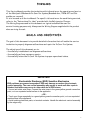
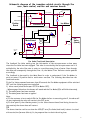
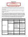
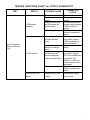
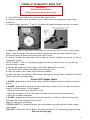
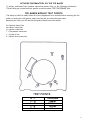
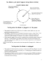
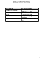
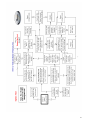
Whirlpool Europe
Service Consulting Center
General Icemaker Information Letter
In Door Ice & Ice-Maker system
Side by Side production Cassinetta
Index
Forward
Theory of Operation
Schematic Diagram
Ice Valve Feed-back Description
Optics Diagnostic Mode Test
Optics Troubleshooting Chart
Power Up Diagnostic Mode Test
Power Up Troubleshooting Chart
Ice Maker Module Test Points
Ice Maker Module Detailed Operation
The Ice Maker Module Cycle
Testing when Ice Maker is plugged in
Testing when Ice Maker is unplugged
Module Specification
Frequently Asked Questions
Optics Test Flow Chart
Power Up Test Flow Chart
3
4
5
5
6
7
8
10
11
12
13
13
13
14
15
16
17
2
FORWARD
This Service Manual provides the technician with information on the operation and service
of the Whirlpool & Bauknecht In-Door Ice System (Rounded door, TRIM-KIT and Flat
models are covered).
It is to be used as a Service Manual. For specific information on the model being serviced,
refer to the “Instructions For User” provided with the Refrigerator/Freezer.
The Wiring Diagrams used in this document are typical and should be used for
service/training purposes only. Always use the Wiring Diagram supplied with the product
when servicing the unit.
GOALS AND OBJECTIVES
The goal of this document is to provide detailed information that will enable the service
technician to properly diagnose malfunctions and repair the In-Door Ice System.
The objectives of this document are to:
• Successfully troubleshoot and diagnose malfunctions.
• Successfully perform necessary repairs.
• Successfully return the In-Door Ice System to proper operational status.
IMPORTANT
Electrostatic Discharge (ESD) Sensitive Electronics
ESD problems are present everywhere. ESD may damage or weaken the electronic
control assembly. The new control assembly may appear to work well after repair is
finished, but failure may occur at a later date due to ESD stress.
• Use an anti-static wrist strap. Connect the wrist strap to the green/yellow ground connection
point, or to an unpainted metal surface in the appliance.
- OR • Touch your finger repeatedly to a green/yellow ground connection point, or to an unpainted
metal surface in the appliance.
• Avoid touching electronic parts, or terminal contacts. Handle the electronic control assembly
by the edges only.
3
Theory of operation
The IDI Ice Maker system consists of the following: an Ice Maker, an electronic ice level
sensor, an external water valve, and a freezer door compartment-mounted ice storage bin.
The Ice-Maker control module is a stamped circuit that provides power and control for
the ice making loads, which consist of the motor, heater, and water valve.
The Ice harvesting process begins when the ice maker thermostat closes and signals that
the harvest temperature has been reached. The closed thermostat applies power to the
ice maker motor and to the heater. As the heater melts the outer layer of the ice, the
motor rotates a rake, which sweeps the ice cubes out of the mould, and into the storage
bin.
Due to the placement of the storage bin on the freezer door the sensing of the ice level is
made by an electronic control that performs this function, and two additional functions.
It controls power to the ice maker, and performs system diagnostic, which includes a
power up test, and service diagnostic.
The electronic control consists of two separate printed circuit boards mounted on
opposite sides of the freezer liner just inside the door. The board mounted on the freezer
door hinge-side of the cabinet is referred to as the “emitter board”, and the board
mounted on the mullion side is referred to as the “receiver board”.
When the Ice-Maker thermostat closes and signals the ice is ready to be harvested, the
emitter board sends out an infrared (IR) pulse. If the path of the pulse is unobstructed to
the receiver board, the phototransistor on the receiver board will “sense” the pulse. The
control will then energise a relay, which applies power to the ice maker. And a harvest
begins.
The ice maker loads, the motor, the heater, and water valve, is controlled by the stamped
circuit module, which is part of the ice maker. The electronic control will check
periodically to see if the ice maker is at the home/park position, (when the ejector stops
at the 2 o’clock position). If the ejector is at the home position, the relay will de-energize,
and remove power from the ice maker until the next harvest.
To prevent an early harvest from occurring after the last harvest is completed, a minimum
of 40 minutes must pass before another harvest will be initiated.
4
Schematic diagram of the icemaker related circuits through the
user, main control, emitter and receiver boards
7,5 secondi CLOSED
(mechanical contact)
Line
3
2
Line x Ice-Maker
1
SW1
2
+5VDC
RELE' RL1
R1
Bimetallo
1 1
Heater
uP
Feed-back
R2
2
LED Cathode
Emitter
Board
Receiver IR
Ice-Maker
Neutral
User Interface
Line
Line
N
L
RX
Main Board
Neutral
+
3
L
N
Feed-back
Ice valve
Ice
Valve
(black)
TX
+5VDC
Main plug
220Vac
Water Filter
Indicator
uP
1
Relè
2 Ice-Maker
Neutral
Ice Valve Feed-back Description
The feedback Ice Valve mainly gives the information to the microprocessor on how many
times the Ice Valve has been engaged. This value is recorded by the microprocessor and it is
multiplied by the valve flow rate in order to record how many litres of water flows through
the valve and consequently through the filter. So, the Water Filter Indicator can be updated
accordingly.
The feedback is also used by the Main Board in order to understand if the Ice-Maker is
stuck at water fill position and to avoid water overflow. The following describes how the
feed-back works:
If the Ice-Valve command lasts more than 20 seconds the Ice-Maker equipment will be switched
OFF until the following points are satisfied:
1) Alarm reset (alarm and buzzer OFF/Ice-Maker OFF).
- When engaged this alarm the buzzer will sound and the Ice Mode LED’s will blink alternately.
2) The mains power has been removed
3) The mains power has been re-applied
Note:
a) If the customer tries to switch ON the Ice-Maker before to executing point 2, the alarm will
re-start again and the relay will remain in the OFF state.
b) If after point 3) the situation persist (i.e. the failure has not been fixed during the service
intervention) the above alarm will restart.
TIP
The above situation could occur when the VIOLET wire (Ice Valve feed-back) is short-circuited
with a main Line (harness failure). So, be prepared also to check the wiring loom.
5
Diagnostics
WARNING
WARNING
Electrical Shock Hazard
Voltage is present during these tests.
OPTICS DIAGNOSTIC MODE TEST
The service diagnostics mode only checks the functionality of the optics. To enter this mode,
open the freezer door anytime when power has been applied for at least one minute. The
status LED should flash twice, then pause for 1 second, then repeat this sequence as long as
the door is open.
If the user pushes in the flapper door on the emitter, the optics path should be cleared, and
the LED should be on solid. The service diagnostics mode cannot be entered if the icemaker
is in the middle of a harvest.
NOTES:
1. Optics Diagnostics will not respond for 5 minutes after the ice maker begins a “harvest”
cycle. To reset the control, wait until the ice maker “parks”, then switch off the Ice-maker
by means the User Board for 5 seconds, and repeat the test. To determine if the icemaker
is in the harvest mode, press in the door switch and look at the status LED. When the door
switch is pushed in during a harvest, the status LED will flash on and off one pulse every
second. If the IDI control is in the diagnostics mode it cannot enter the harvest mode.
2. The ice bin must be on the door and the ice level below the notched openings.
OPTICS DIAGNOSTICS PROCEDURE FOR WER SbS DESIGN BOARDS
STEP #
STATUS LED
ACTION
The flapper door on
the emitter is blocking
the infrared beam.
Go to step 2
The optics are faulty.
Go to step 2
Ice maker is in the
“harvest” mode. The
harvest mode consists
of a five (5) minute
period that starts
when the bimetal
closes, and the ice
maker begins to run.
To confirm, press in
and hold the freezer
door switch. If in the
“harvest” mode, the
Status LED will flash
once every second.
Faulty status LED.
Replace the receiver
and emitter boards.
Two (2) pulses followed
by a one (1) second
delay (repeated).
The optics are faulty.
Replace the emitter and
receiver boards.
LED is on steady.
The optics are
working properly.
Close the freezer door.
Two (2) pulses followed
by a one (1) second
delay (repeated).
1. Open the Freezer
door.
No lamp.
2. Press in the emitter
flapper door to clear the
optics beam.
POSSIBLE CAUSES
6
TROUBLE SHOOTING CHART for OPTICS DIAGNOSTIC
TEST
RESULT
2 LED pulses
repeated.
POSSIBLE CAUSE
Dirt on optics.
Frost on optics
lenses.
Flapper door is open
and is blocking the
emitter beam.
Failed optics.
Ice maker is in 5
minutes “harvest”
cycle.
Optics Diagnostic
Mode (optics test
only)
No LED pulses.
Incorrect wiring at
emitter or receiver
board.
Optics performing
self-tests (will not
perform diagnostic
tests during this time).
LED is defective.
5 second LED on
steady.
Flapper door is held
closed.
CORRECTIVE
ACTION
Clean dirt from optics.
Clean frost from
lenses.
Hold the emitter door
closed, and the status
LED should be on
steady.
Replace emitter and
receiver boards and
retest.
To verify, press in on
door switch. Status
LED should flash at 1
second intervals.
Correct wiring and
retest.
Make sure ice maker
is “parked.” Switch
OFF the Ice-Maker by
means the User
Board for 5 seconds
to reset optics control
and retest.
Replace emitter and
receiver boards and
retest.
Normal with flapper
door closed.
7
POWER-UP DIAGNOSTIC MODE TEST
WARNING
Electrical Shock Hazard
Voltage is present during these tests.
1. Switch OFF the Ice-Maker using the User Board push-button.
2. Slide the ice maker out of the mounting rails; remove the cover leaving the wiring harness
connected.
3. Connect jumper test holes “T” and “H” to bypass the bimetal thermostat and start a harvest.
4. Make sure there is a clear path across the bin for the infrared beam to travel to the receiver
sensor. Close the freezer door and switch on the system using the User Board ON/OFF pushbutton then wait 5 seconds to allow the optics relay to close.
5. Open the freezer door and observe the ice maker. A “harvest” should be in progress; i.e. the ice
cube rake is turning.
NOTE: If holes “T” and “H” are properly jumpered and the ice maker will not run, stop the test,
and check the ice maker
6. Remove the jumper before the fingers reach 10:00. Reinstall the ice maker.
7. Switch OFF the Ice-Maker immediately after the water fills.
8. With the freezer door closed, switch ON the Ice-Maker.
9. Wait 5 seconds, to a maximum of 50 seconds, then open the freezer door, and watch the Status
LED for one of the following codes
Status LED Output Codes
4 PULSES, repeated once, indicates the relay is defective. Replace both the emitter and receiver
boards.
3 PULSES, repeated once, indicates the optics and relay are okay, but the ice maker is not being
sensed, or will not operate. If this happens:
• Check the bail arm switch to make sure it is On
• Check the ice maker circuit and the connections back to the receiver board and neutral.
• Check the ice maker components.
2 PULSES, repeated once, indicates the optics are blocked, or defective. Clear the optics path,
and repeat the “Optics Diagnostics Procedure.”
Replace both boards, if necessary.
STEADY LIGHT for 5 seconds indicates the relay and optics are okay, and the receiver senses
the ice maker.
NO LIGHT: Switch OFF the Ice-Maker, using the User Board, for 5 seconds and repeat the test.
See note on next page
8
FURTHER NOTE:
During the first minute after Ice-Maker power is cycled from OFF to ON, the IDI control
will go through a power up diagnostics routine if the freezer compartment door is closed
when power is first applied. The freezer door can be opened at any time during the first
minute to check the status LED located on the receiver, which will indicate the results of
the power up test. The results of the power up tests are displayed on the status LED as
follows:
a) LED on solid for 5 seconds = all tests pass.
b) LED flashes twice then off for one second and repeats 2 flashes = optics problem.
Sending a pulse from the emitter to the receiver performs the optics test. If the
receiver gets it, the test passed.
c) LED flashes 3 times then off for a second and repeats 3 flashes = icemaker problem.
The icemaker test is performed by checking for a load (<10Mohm) between the AC line to
the icemaker (pin 4) and neutral (pin 8). If a load is present the icemaker test is passed.
d) LED flashes 4 times then off for a second and repeats 4 flashes = relay problem. The
relay that supplies power to the icemaker is cycled during the power up test. If the
relay doesn’t close it doesn’t pass the test (receiver board is defective).
If multiple failure modes exist, the status LED will only display one of them. If the freezer
door is open when power is applied, diagnostics are skipped and the main routine is started.
Once the door is closed again and the power-up diagnostics have indicated that all tests
passed, the IDI control will begin to monitor the icemaker.
9
TROUBLE SHOOTING CHART for
POWER-UP DIAGNOSTIC
TEST
RESULT
Defective receiver relay.
3 LED pulses repeated.
Ice Maker in “park”
position and bimetal is
open.
Ice Maker bail arm
switch in OFF position.
Ice Maker is not
powered.
Thermal fuse in Ice
Maker harness is open.
Incorrect wiring at emitter
or receiver board.
Problem with Ice Maker
Ice Maker
Control Circuit
2 LED pulses.
5 second LED on steady.
No LED pulses.
No power applied to Ice
Maker module.
Ice Maker
Checks
POSSIBLE CAUSE
4 LED pulses repeated
once.
Ejector bar does not
move.
Heater is not on.
No water fill.
Optics board defective.
Ice Maker control circuit
is functioning normally.
Optics performing selftests (will not perform
diagnostic tests during
this time)
Optics check not run
before testing Ice Maker
Freezer door not closed
after Optics test.
Optics path not clear.
Optics test failure.
Ice Maker is not
powered.
Thermal fuse in Ice
Maker harness is open.
Install jumper in ice maker holes
“T” and “H” and retest.
Bail arm not used in these models
but switch must be ON.
Switch ON the Ice Maker by
means the User Board and retest.
Replace ice maker harness and
retest.
Correct wiring and retest.
See "Ice Maker Checks” below.
Replace emitter and receiver
boards and retest.
None required.
Make sure ice maker is “parked.”
Unplug refrigerator for 5 seconds
to reset optics control and retest.
Run optics test and recheck ice
maker.
Close freezer door to start
harvest.
Clear optics path.
Replace emitter and receiver
boards and retest.
Checks poles relay output on the
Main Board.
Replace ice maker harness.
Wiring harness problem.
Check continuity in wiring
harness.
Motor has failed.
Replace ice maker module.
Thermostat jumper not
making contact.
Heater has failed
Thermostat jumper was
left installed past 11:00
position.
Water valve wiring
connection problem.
Customer’s water supply
is problem.
Frozen water fill tube.
Ejector bar does not stop
at “home” position.
CORRECTIVE ACTION
Replace emitter and receiver
boards and retest.
Water valve has failed.
Thermostat jumper not
removed.
Reposition jumper.
Replace ice maker.
Remove jumper by 10:00 position
of ejector bar.
Check wiring to valve.
Check for proper water supply.
Defrost the water fill tube and
check for seeping valve.
Replace water valve.
Remove thermostat jumper.
10
DETAILED INFORMATION ON THE ICE MAKER
To better understand the icemaker operations please refer to the following information.
This will allow you to deal with the system in case the above TEST PROCEDURE fails.
ICE MAKER MODULE TEST POINTS
The design of this Ice maker allows all of the components to be tested without removing the Ice
maker or moving the refrigerator away from the wall to access the water valve.
Removing the cover you wiil see the test points identified on the module.
N = Neutral side of line
M = Motor connection
H = Heater connection
T = Thermostat connection
L = L1 side of line
V = Water valve connection
H-T
L–H
L–M
L-N
V-N
Thermostat
Heater
AC Motor
220Vac
Valve
11
ICE MAKER MODULE DETAILED OPERATION
When the thermostat has sensed low temperatures (about –8°C), the thermostat (called also
Bimetal) closes. At this time, the current has a path through the thermostat to motor because the
contact b is connected to the contact c (see wiring diagram below).
Neutral from Main Board (pin 15)
VIOLET
Main Board Side by Side
Ice-Maker Side by Side
4 poles
+5Vdc
Line from Receiver board relay
BLUE
2
1
GREEN/BROWN
4
3
N
L
Contact A
V
12 poles
Ice valve
feed-back
Heater 300 ohm
uP
16 poles
Contact B
H
pin 8 (VIOLET)
short-circuit
Bimetal
T
Shut-Off
Switch
Thermostat
pin 1 (BROWN)
pin 4 (BLACK)
6 poles
Off (Up)
Water valve
(BLACK)
Contact C
M
M
Neutral
On (Dn)
Contact D
Motor AC
21K ohm
The motor is linked with the drive gear. From the module, there are copper contact (a. b. c and d)
that ride on copper; strips on the backside of the drive gear. As the drive gear rotates, these
contacts from the module will make or break a circuit (track) to the copper strips to generate the
Ice maker cycle.
When the bimetal opens the motor runs anyway because the c and d contacts are connected
together, these contact will be connected together until the blades are at Home/Park position
(contacts c not more connected to contacts d). During the rotation the contacts b and a will be
connected together about 7,5 seconds to drive water valve in this case the current has a path
through the heater.
Contacts rotate clockwise
and tracks are static.
12
Ice-Maker cycle (what happens during blade rotation)
PLASTIC WHEEL VIEW
Water valve energized 7,5
seconds 140cc Fill (about
11:00 o'clock)
Ejector blade Park/Stop
Position (about 2 o'clock)
Start position Bimetal Closes
(Motor ON, Heater ON)
Ejector Stalls On Ice
Motor ON, Heater On
(1/2 Minute To 5 Minutes
About 4 o'clock Position)
Thermostat Opens In This
Range Of Operation
Then Heater goes OFF
6 o'clock position
Testing when Ice Maker is plugged in to the power
Test points L & N will verify 220 Volts to Ice Maker module. (Make sure your test
probes go into the test points ½”)
• Test points T & H will verify if the bimetal thermostat is open or closed. Short T & H
with an insulated piece of wire (14 ga.) to run the motor. If the motor doesn’t run,
replace the module assembly. If the motor runs, replace the bimetal thermostat.
• If you leave the jumper in for a half of a revolution, you can feel the heater in the moid
heat up…if it’s good. Remove the jumper and the water valve will be energized in the
last half of the revolution. (Make sure that the freezer temperature is cold enough to
close the bimetal)
NOTE: Do not short any contacts other than those specified. Damage to Ice – Maker can
result.
•
Testing when Ice Maker is unplugged
•
•
Test points L & H will check the resistance of the heater (300 ohm). Replace the mold
and heater assembly if not near this value (+ or – 10 ohms) (Ejector blades should be at
the end of the cycle position)
Test points L & M will check the resistance of the motor (about 21500 ohms). Replace
module assembly if not near this value (+ or – 10 ohms). (Module must be separated
from heater before testing).
13
MODULE SPECIFICATION
MOLD HEATER
THERMOSTAT (Bimetal)
WATER FILL
MOTOR
MODULE
CYCLE
185 Watts, 300ohms
Close 17°F ± 3°F (-8°C)
Open 32°F ± 3°F (0°C)
140cc
3 Watts, 21000 ohms
Stamped circuit, Plug-in
connectors
One revolution (ejects & water
fill)
14
Frequently Asked Question
1) Does the Ice button on the user board close a relay on the main control board?
The User Board has got a microprocessor that detects which of the 13 push-buttons has been depressed and
communicates this code to the Main Board. So, keep in mind there are no wiring connection between relay IceMaker and User Board.
2) Does this relay supply the emitter board and the receiver board?
NOT COMPLETELY CORRECT. It supplies the Neutral to the Receiver board and to the Ice-Maker.
3) On the receiver board the relay closes to supply the Ice-Maker Module and remains closed while the infrared
beam is not broken.?
NOT COMPLETELY CORRECT. The relay closes every 40 minutes if the infrared beam is not broken. Hence, it
remains closes, only if the bimetal inside the Ice-Maker is closed (resistance load check). This situation allows a
harvest (about 5 minutes). So, usually the receiver board relay is closed 5 minutes every 40 minutes if some
condition are true.
4) Which board controls the 40 minutes, delay in harvesting, why is there a delay and can it be overridden?
The delay in harvesting is controlled by the Receiver board, it is at the moment 40 minutes it can be overridden at
power-up (components diagnostic) if the Ice-Maker internal bimetal is closed, etc.
5) Can the output from the switch on the user board be tested?
The ON/OFF Ice-Maker push-button is not connected by wiring to the Main Board it is connected to the User
Board microprocessor by PCB trace and once de-pressed its code is sent to the Main Board by means the
communication wires (RX and TX). This allows to engage/disengage the relay that supplies the Neutral side of the
Line to the system. So you can test it, unless the communication is not working, by means a MULTIMETER. You
should see main voltage between pole 15 or 16 (connector 16 poles) and poles from 1 to 5 (same connector 16 poles)
when the relay is engaged (Ice-Maker push-button ON) and no any voltage when the relay is not engaged (IceMaker push-button OFF).
6) How would the output from the relay and other outputs from the main control board be tested?
My opinion is to TEST it by means a MULTIMETER or a LAMP, usually there is Main Voltage signal to check.
7) How does the receiver or other component detect the closure of the icemaker thermostat to energise the
relay?
The icemaker thermostat closes by itself when it reaches the required temperature, the receiver every 40
minutes closes the internal relay (if the infrared beam is not broken) and by means internal resistor (feed-back)
the receiver microprocessor detects the load resistance value (two different value are possible depending if the
bimetal is closed or not). If the bimetal is closed the relay stays engaged to allow the harvest (about 5 minutes)
till the Ice-Maker reaches the park position.
8) How does the receiver or other component detect the park position of the ice-maker to de-energise the relay?
The receiver detects the same value as for bimetal closed when the motor is. The park position automatically stop
the Ice-Maker if the bimetal is open and opens the connection between the receiver relay output and the IceMaker motor. So, the receiver by means the feed-back (internal resistor) detect the end of the harvest.
9) What are all the circumstances that would cause the receiver relay to open cutting the voltage to the icemaker? This is the factor that causes most difficulty when testing. Knowing whether a no voltage situation is
correct due to the normal function of the boards or if one of them is faulty.
Mainly the relay opens when it doesn’t detect anymore the Ice-Maker motor connection that at the beginning is
allowed by the bimetal in closed position and during the harvest time by means the internal Ice-Maker contacts c
& d (these are connected together until the park-position). Of course the infrared beam mustn’t be broken, etc.
15
16
17