1
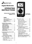
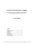
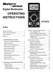
OPERATING
INSTRUCTIONS
CP7665
SAFETY GUIDELINES
TO PREVENT ACCIDENTS THAT COULD RESULT IN SERIOUS
INJURY AND/OR DAMAGE TO YOUR VEHICLE OR TEST
EQUIPMENT, CAREFULLY FOLLOW THESE SAFETY RULES AND
TEST PROCEDURES
• Always wear approved eye
protection.
• Always operate the vehicle in a
well ventilated area. Do not inhale
exhaust gases – they are very
poisonous!
• Always keep yourself, tools and
test equipment away from all
moving or hot engine parts.
• Always make sure the vehicle is in
park (Automatic transmission) or
neutral (manual transmission) and
that the parking brake is firmly
set. Block the drive wheels.
• Never lay tools on vehicle battery.
You may short the terminals
together causing harm to yourself,
the tools or the battery.
• Never smoke or have open flames
near vehicle. Vapors from gasoline
and charging battery are highly
flammable and explosive.
• Never leave vehicle unattended
while running tests.
• Always keep a fire extinguisher
suitable for gasoline/electrical/
chemical fires handy.
• Always use extreme caution when
working around the ignition coil,
distributor cap, ignition wires, and
spark plugs. These components
contain High Voltage when the
engine is running.
• Always turn ignition key OFF
when connecting or disconnecting electrical components, unless
otherwise instructed.
• Always follow vehicle
manufacturer’s warnings,
cautions and service procedures.
CAUTION:
Some vehicles are equipped with safety air bags. You must follow vehicle
service manual cautions when working around the air bag components or
wiring. If the cautions are not followed, the air bag may open up unexpectedly, resulting in personal injury. Note that the air bag can still open up
several minutes after the ignition key is off (or even if the vehicle battery is
disconnected) because of a special energy reserve module.
Section 1. Multimeter Basic Functions
Digital multimeters or DMMs have many special features and functions. This
section defines these features and functions, and explains how to use these
functions to make various measurements.
1
11
5
10
3
2
8
7
4
9
6
Functions and Display Definitions
1. ROTARY SWITCH
Switch is rotated to turn multimeter
ON/OFF and select a function.
ing the resistance of a component
in an electrical circuit in the range
of 0.1Ω to 20MΩ. (Ω is the electrical symbol for Ohms)
2. DC VOLTS
This function is used for measuring DC (Direct Current) Voltages in
the range of 0 to 500V.
4. DIODE CHECK
This function is used to check
whether a diode is good or bad.
3. OHMS
This function is used for measur-
5. HOLD
Press HOLD button to retain data
on display. In the hold mode, the
"H" annunciator is displayed.
6. TEST LEAD JACKS
BLACK Test Lead is
always inserted in the
COM jack.
RED Test Lead is inserted in the jack corresponding to the multimeter rotary switch setting.
Always connect TEST LEADS to the
multimeter before connecting them
to the circuit under test!!
10. DISPLAY LIGHT
Press button to illuminate the display.
11. DISPLAY
Used to display all measurements
and multimeter information.
Low Battery – If this symbol appears in the lower left corner of the
display, then replace the internal
9V battery. (See Fuse and Battery
replacement on
page 7.)
High Voltage
indicator
DC AMPS
DC VOLTS AC VOLTS
OHMS
DIODES
1.5V, 9V and 12V
BATTERY TESTS
7. AC VOLTS
This function is used for measuring AC Voltages in the range of 0
to 500V.
8. DC AMPS
This function is used for measuring DC (Direct Current) Amps in
the range of 0 to 10A.
9. 1.5V, 9V, AND 12V BATTERY
TEST
This function is used to test 1.5V,
9V, and 12V batteries under
load.
Overrange Indication – If “1” or “1” appears on the
left side of the display, then the multimeter is set to a
range that is too
small for the
present measurement being taken.
Increase the range until this disappears. If it does not disappear after
all the ranges for a particular function have been tried, then the value
being measured is too large for the
multimeter to measure. (See Setting the Range on page 6.)
Zero Adjustment
The multimeter will automatically zero
on the Volts, Amps and Battery Test
functions.
Automatic Polarity Sensing
The multimeter display will show a minus
(-) sign on the DC Volts and DC Amps
functions when test lead hook-up is reversed.
Setting the Range
Two of the most commonly asked
questions about digital multimeters
are What does Range mean? and
How do I know what Range the multimeter should be set to?
What Does Range mean?
Range refers to the largest value
the multimeter can measure with
the rotary switch in that position. If
the multimeter is set to the 20V DC
range, then the highest voltage the
multimeter can measure is 20V in
that range.
EXAMPLE: Measuring Vehicle Battery Voltage (See Fig. 1)
Fig. 2
Red
Black
the display. If you are in the highest
range and the multimeter is still
showing that it is overranging, then
the value being measured is too
large for the multimeter to measure.
How do I know what Range the
multimeter should be set to?
Fig. 1
The multimeter should be set in the
lowest possible range without
overranging.
EXAMPLE: Measuring an unknown
resistance
Red
Black
Let’s assume the multimeter is connected to the battery and set to the
20V range.
The display reads 12.56. This means
there is 12.56V across the battery
terminals.
Let’s assume the multimeter is connected to an engine coolant sensor
with unknown resistance. (See Fig. 3)
Start by setting the multimeter to the
largest OHM range. The display
reads 0.0Ω or a short circuit.
Fig. 3
Now assume we set the multimeter
to the 2000mV range. (See Fig. 2)
The multimeter display now shows
a “1” and nothing else. This means
the multimeter is being overranged
or in other words the value being
measured is larger than the current
range. The range should be increased until a value is shown on
Red
Black
Fig. 4
Fig. 5
This sensor can’t be shorted so reduce the range setting until you get
a value of resistance.
At the 200KΩ range the multimeter
measured a value of 4.0. This means
there is 4KΩ of resistance across
the engine coolant sensor terminals. (See Fig. 4)
If we change the multimeter to the
20KΩ range (See Fig. 5) the display shows a value of 3.87KΩ. The
actual value of resistance is 3.87KΩ
and not 4KΩ that was measured in
the 200KΩ range. This is very important because if the manufacturer
specifications say that the sensor
should read 3.8-3.9KΩ at 70°F then
on the 200KΩ range the sensor
would be defective, but at the 20KΩ
range it would test good.
Now set the multimeter to the 2000Ω
range. (See Fig. 6) The display will
indicate an overrange condition because 3.87KΩ is larger than 2KΩ.
This example shows that by decreasing the range you increase the
accuracy of your measurement.
When you change the range, you
change the location of the decimal
point. This changes the accuracy of
the measurement by either increas-
Fig. 6
ing or decreasing the number of
digits after the decimal point.
Battery and Fuse
Replacement
Important: A 9 Volt battery must be
installed before using the digital multimeter. (see procedure below for
installation)
Battery Replacement
1. Turn multimeter rotary
switch to OFF position.
2. Remove test leads from
multimeter.
3. Remove screws from back of
multimeter.
4. Remove back cover.
5. Install a new 9 Volt battery.
6. Re-assemble multimeter.
Fuse Replacement
1. Turn multimeter rotary
switch to OFF position.
2. Remove test leads from
multimeter.
3. Remove screws from back of
multimeter.
negative (-) side of voltage
source.
4. Remove back cover.
NOTE: If you don’t know which
side is positive (+) and which
side is negative (-), then arbitrarily connect the RED test lead
to one side and the BLACK to
the other. The multimeter automatically senses polarity and will
display a minus (-) sign when
negative polarity is measured. If
you switch the RED and BLACK
test leads, positive polarity will
now be indicated on the display.
Measuring negative voltages
causes no harm to the multimeter.
5. Remove fuse.
6. Replace fuse with same size
and type as originally
installed!
5mm x 20mm, 200mA, 250V,
fast acting.
7. Re-assemble multimeter.
Measuring DC Voltage
This multimeter can be used to measure DC voltages in the range from 0
to 500V. You can use this multimeter
to do any DC voltage measurement
called out in the vehicle service
manual. The most common applications are measuring voltage drops,
and checking if the correct voltage
arrived at or is being produced by a
sensor or a particular circuit.
To measure DC Voltages (see Fig. 7):
1. Insert BLACK test lead into
COM test lead jack.
5. Turn multimeter rotary switch
to desired voltage range.
If the approximate voltage is unknown, start at the largest voltage
range and decrease to the appropriate range as required. (See
Setting the Range on page 6)
6. View reading on display - Note
range setting for correct units.
NOTE: 200mV = 0.2V
2. Insert RED test lead into
test lead jack.
3. Connect RED test lead to positive (+) side of voltage source.
4. Connect BLACK test lead to
Fig. 7
Measuring AC Voltage
This multimeter can be used to measure AC voltages in the range from
0 to 500V.
To measure AC Voltages (see Fig. 8):
Fig. 8
Red
Black
Red
Black
1. Insert BLACK test lead into
COM test lead jack.
2. Insert RED test lead into
test lead jack.
Fig. 9
Unknown
Resistance
3. Connect RED test lead to one
side of voltage source.
4. Connect BLACK test lead to other
side of voltage source.
5. Turn multimeter rotary switch
to desired voltage range.
If the approximate voltage is unknown, start at the largest voltage
range and decrease to the appropriate range as required. (See
Setting the Range on page 6)
6. View reading on display.
NOTE: 200mV = 0.2V
Measuring Resistance
Resistance is measured in electrical
units called ohms (Ω). The digital
multimeter can measure resistance
from 0.1Ω to 20MΩ (or 20,000,000
ohms). Infinite resistance is shown
with a “1” on the left side of display
(See Setting the Range on page 6).
You can use this multimeter to do any
resistance measurement called out
in the vehicle service manual. Testing ignition coils, spark plug wires,
and some engine sensors are common uses for the OHMS (Ω) function.
To measure Resistance (see Fig. 9):
1. Turn circuit power OFF.
To get an accurate resistance
measurement and avoid possible
damage to the digital multimeter
and electrical circuit under test,
turn off all electrical power in the
circuit where the resistance measurement is being taken.
Black
Red
2. Insert BLACK test lead into
COM test lead jack.
3. Insert RED test lead into
test lead jack.
4. Turn multimeter rotary switch
to 200Ω range.
Touch RED and BLACK multimeter leads together and view
reading on display.
Display should read typically
0.2Ω to 1.5Ω.
If display reading was greater
than 1.5Ω, check both ends of
test leads for bad connections.
If bad connections are found,
replace test leads.
5. Connect RED and BLACK test
leads across component
where you want to measure
resistance.
When making resistance measurements, polarity is not important. The test leads just have
to be connected across the component.
6. Turn multimeter rotary switch
to desired OHM range.
If the approximate resistance is
unknown, start at the largest OHM
range and decrease to the appropriate range as required.
7. View reading on display - Note
range setting for correct units.
To measure DC Current (see Figs.
10 & 11):
NOTE: 2KΩ = 2,000Ω; 2MΩ =
2,000,000Ω
1. Insert BLACK test lead into
COM test lead jack.
If you want to make precise resistance measurements, then
subtract the test lead resistance
found in Step 4 above from the
display reading in Step 7. It is a
good idea to do this for resistance measurements less than
10Ω.
2. Insert RED test lead into "10A"
test lead jack or "mA" test lead
jack.
3. Disconnect or electrically
open circuit where you want
to measure current.
This is done by:
• Disconnecting wiring harness.
Measuring DC Current
This multimeter can be used to measure DC current in the range from 0 to
10A. Unlike voltage and resistance
measurements where the multimeter
is connected across the component
you are testing, current measurements must be made with the multimeter in series with the component.
Isolating current drains and short circuits are some DC Current applications.
Fig. 10
Electrical
Device
DC
Voltage
Source
Red
Black
Fig. 11
Electrical
Device
DC
Voltage
Source
Red
Black
• Disconnecting wire from
screw-on type terminal.
• Unsolder lead from component
if working on printed circuit
boards.
• Cut wire if there is no other
possible way to open electrical circuit.
4. Connect RED test lead to one
side of disconnected circuit.
5. Connect BLACK test lead to
remaining side of disconnected circuit.
6. Turn multimeter rotary switch
to 10A DC position, 200mA or
200µA position.
7. View reading on display.
If minus (-) sign appears on display, then reverse RED and
BLACK test leads.
Testing Diodes
A diode is an electrical component
that allows current to only flow in one
direction. When a positive voltage,
generally greater than 0.7V, is applied to the anode of a diode, the
diode will turn on and allow current to
flow. If this same voltage is applied to
the cathode, the diode would remain
off and no current would flow. Therefore, in order to test a diode, you must
check it in both directions (i.e. anodeto-cathode, and cathode-to-anode).
Diodes are typically found in alternators on automobiles.
Performing Diode Test (see Fig. 12):
Fig. 12
Anode
Cathode
leads across diode and view
display.
Display will show one of three
things:
• A typical voltage drop of
around 0.7V.
• A voltage drop of 0 volts.
• A “1” will appear indicating the
multimeter is overranged.
7. Switch RED and BLACK test
leads and repeat Step 6.
8. Test Results
If the display showed:
• A voltage drop of 0 volts in
both directions, then the diode
is shorted and needs to be
replaced.
• A “1” appears in both directions, then the diode is an open
circuit and needs to be replaced.
Red
Black
1. Insert BLACK test lead into
COM test lead jack.
2. Insert RED test lead into
test lead jack.
3. Turn multimeter rotary switch
to
function.
4. Touch RED and BLACK test
leads together to test continuity.
Check display – should reset to
0.00.
5. Disconnect one end of diode
from circuit.
Diode must be totally isolated
from circuit in order to test its
functionality.
6. Connect RED and BLACK test
• The diode is good if the display reads around 0.5V–0.7V
in one direction and a “1” appears in the other direction
indicating the multimeter is
overranged.
Testing 1.5V, 9V and
12V Batteries
Test Procedure (see Fig. 13):
Fig. 13
Red
Black
Red
Black
1. Insert BLACK test lead into
COM test lead jack.
2. Insert RED test lead into
test lead jack.
3. Turn multimeter rotary switch
range.
to 1.5V, 9V or 12V
4. Connect RED test lead to positive (+) terminal of battery.
5. Connect BLACK test lead to
negative (-) terminal of battery.
6. View reading on display.
Section 2. Automotive Testing
The digital multimeter is a very useful tool for trouble-shooting automotive electrical systems. This section
describes how to use the digital multimeter to test the starting and charging system, ignition system, fuel
system, and engine sensors. The
digital multimeter can also be used
for general testing of fuses, switches,
solenoids, and relays.
• If the reading is overrange Fuse is blown and needs to be
replaced.
NOTE: Always replace blown
fuses with same type and rating.
Testing Switches
This test checks to see if a switch
“Opens” and “Closes” properly.
To test Switches (see Fig. 15):
General Testing
The digital multimeter can be used
to test fuses, switches, solenoids,
and relays.
Fig. 15
Typical "Push"
Button Switch
Testing Fuses
This test checks to see if a fuse is
blown.
Red
Black
To test Fuses (see Fig. 14):
Fig. 14
1. Insert BLACK test lead into
COM test lead jack.
Fuse
2. Insert RED test lead into
test lead jack.
Red
Black
1. Insert BLACK test lead into
COM test lead jack.
2. Insert RED test lead into
test lead jack.
3. Turn multimeter rotary switch
to 2000Ω function.
4. Connect RED and BLACK test
leads to opposite ends of fuse.
• If the reading is zero - Fuse is
good.
3. Turn multimeter rotary switch
to 2000Ω function.
4. Connect BLACK test lead to
one side of switch.
5. Connect RED test lead to other
side of switch.
• If the reading is zero - The
switch is closed.
• If the reading is overrange The switch is open.
6. Operate switch.
• If the reading is zero - The
switch is closed.
• If the reading is overrange The switch is open.
7. Repeat Step 6 to verify switch
operation.
Testing Solenoids
and Relays
This test checks to see if a solenoid
or relay has a broken coil. If the coil
tests good, it is still possible that the
relay or solenoid is defective. The
relay can have contacts that are
welded or worn down, and the solenoid may stick when the coil is energized. This test does not check for
those potential problems.
To test Solenoids and Relays (see
Fig. 16):
Fig. 16
Relay or
Solenoid
Black
Red
1. Insert BLACK test lead into
COM test lead jack.
2. Insert RED test lead into
test lead jack.
3. Turn multimeter rotary switch
to 200 Ω function.
Most solenoids and relay coil
resistances are less than 200Ω.
4. Connect BLACK test lead to
one side of coil.
5. Connect RED test lead to other
side of coil.
6. View reading on display.
• Typical solenoid / relay coil resistances are 200Ω or less.
• Refer to vehicle service manual
for the device's resistance
range.
If meter overranges, turn multimeter rotary switch to next higher
range. (see Setting the Range
on page 6)
7. Test Results
Good Solenoid / Relay Coil: Display in Step 6 is within manufacturers specification.
Bad Solenoid / Relay Coil:
• Display in Step 6 is not within
manufacturers specifications.
• Display reads overrange on
every ohms range indicating an
open circuit.
NOTE: Some relays and solenoids have a diode placed across
the coil.
Starting/Charging System Testing
The starting system “turns over” the engine. It consists of the battery, starter
motor, starter solenoid and/or relay, and associated wiring and connections.
The charging system keeps the battery charged when the engine is running.
This system consists of the alternator, voltage regulator, battery, and
associated wiring and connections. The digital multimeter is a useful tool for
checking the operation of these systems.
No Load Battery Test
Before you do any starting/charging
system checks, you must first test
the battery to make sure it is fully
charged.
Test Procedure (see Fig. 17):
6. Connect RED test lead to positive (+) terminal of battery.
7. Connect BLACK test lead to
negative (-) terminal of battery.
8. Turn multimeter rotary switch
to 20V DC range.
9. View reading on display.
Fig. 17
10. Test Results.
Compare display reading in Step
9 with the following chart.
Voltage
Red
Percent
Battery is Charged
12.60V
or greater
100%
12.45V
75%
1. Turn Ignition Key OFF.
12.30V
50%
2. Turn ON headlights for 10 seconds to dissipate battery surface charge.
12.15V
25%
Black
3. Insert BLACK test lead into
COM test lead jack.
4. Insert RED test lead into
test lead jack.
5. Disconnect positive (+) battery
cable.
If battery is not 100% charged, then
charge it before doing anymore starting/charging system tests.
Engine Off Battery
Current Draw
• Refer to vehicle service manual
for manufacturers specific Engine Off Battery Current Draw.
This test measures the amount of
current being drawn from the battery
when the ignition key and engine are
both off. This test helps to identify
possible sources of excessive battery current drain, which could eventually lead to a “dead” battery.
1. Turn Ignition Key and all accessories OFF.
Make sure trunk, hood, and
dome lights are all OFF.
(See Fig. 18)
NOTE: Radio station presets
and clocks are accounted for in
the 100mA typical current draw.
9. Test Results.
Normal Current Draw: Display
reading in Step 8 is within manufacturers specifications.
Excessive Current Draw:
- Display reading in Step 8 is
well outside manufacturers
specifications.
- Remove Fuses from fuse box
one at a time until source of
excessive current draw is located.
Fig. 18
Red
Black
2. Insert BLACK test lead into
COM test lead jack.
3. Insert RED test lead into "10A"
(or "mA") test lead jack.
4. Disconnect positive (+) battery
cable.
5. Connect RED test lead to positive (+) battery terminal.
6. Connect BLACK test lead to
positive (+) battery cable.
NOTE: Do not start vehicle during this test, because multimeter
damage may result.
7. Turn multimeter rotary switch
to 10A DC (or 200 mA) position.
8. View reading on display.
• Typical current draw is 100mA.
(1mA = 0.001A)
- Non-Fused circuits such as
headlights, relays, and solenoids should also be checked
as possible current drains on
battery.
- When source of excessive current drain is found, service as
necessary.
Cranking Voltage Battery Load Test
5. Connect BLACK test lead to
negative (-) terminal of battery.
This test checks the battery to see if it
is delivering enough voltage to the
starter motor under cranking conditions.
6. Turn multimeter rotary switch
to 20V DC range.
Test Procedure (see Fig. 19):
Fig. 19
7. Crank engine for 15 seconds
continuously while observing
display.
8. Test Results.
Compare display reading in Step
7 with chart below.
Voltage
Temperature
9.6V or greater 70 °F and Above
Red
Black
9.5V
60 °F
9.4V
50 °F
1. Disable ignition system so vehicle won’t start.
9.3V
40 °F
9.1V
30 °F
Disconnect the primary of the
ignition coil or the distributor pickup coil or the cam/crank sensor
to disable the ignition system.
Refer to vehicle service manual
for disabling procedure.
8.9V
20 °F
8.7V
10 °F
8.5V
0 °F
2. Insert BLACK test lead into
COM test lead jack.
3. Insert RED test lead into
test lead jack.
4. Connect RED test lead to positive (+) terminal of battery.
If voltage on display corresponds to
above voltage vs. temperature chart,
then cranking system is normal.
If voltage on display does not correspond to chart, then it is possible
that the battery, battery cables, starting system cables, starter solenoid,
or starter motor are defective.
Voltage Drops
This test measures the voltage drop across wires, switches, cables, solenoids,
and connections. With this test you can find excessive resistance in the starter
system. This resistance restricts the amount of current that reaches the starter
motor resulting in low battery load voltage and a slow cranking engine at starting.
Test Procedure (see Fig. 20):
1. Disable ignition system so vehicle won’t start.
Disconnect the primary of the
ignition coil or the distributor pickup coil or the cam/crank sensor
to disable the ignition system.
Refer to vehicle service manual
for disabling procedure.
2. Insert BLACK test lead into
COM test lead jack.
3. Insert RED test lead into
test lead jack.
4. Connect test leads.
Refer to Typical Cranking Voltage Loss Circuit (Fig. 20).
• Connect RED and BLACK test
leads alternately between 1 & 2,
2 & 3, 4 & 5, 5 & 6, 6 & 7, 7 & 9,
8 & 9, and 8 & 10.
5. Turn multimeter rotary switch
to 200mV DC range.
If multimeter overranges, turn multimeter rotary switch to the
2000mV DC range. (See Setting
the Range on page 6)
6. Crank engine until steady
reading is on display.
• Record results at each point
as displayed on multimeter.
• Repeat Step 4 & 5 until all
points are checked.
7. Test Results –
Estimated Voltage Drop of
Starter Circuit Components
Component
Voltage
Switches
300mV
Wire or Cable
200mV
Ground
100mV
Fig. 20 Typical Cranking Voltage
Loss Circuit
Solenoid
This is a representative
sample of one type of
cranking circuit. Your vehicle
may use a different circuit
with different components or
locations. Consult your
vehicle service manual.
Starter
Red
Black
Component
Voltage
Battery Cable
Connectors
50mV
Connections
0.0V
• Compare voltage readings in
Step 6 with above chart.
• If any voltages read high, inspect
component and connection for
defects.
• If defects are found, service as
necessary.
Charging System Voltage Test
This test checks the charging system to see if it charges the battery
and provides power to the rest of the
vehicles electrical systems (lights,
fan, radio etc).
Test Procedure (see Fig. 21):
Fig. 21
7. Turn off all accessories and
view reading on display.
• Charging system is normal if
display reads 13.2 to 15.2 volts.
• If display voltage is not between 13.2 to 15.2 volts, then
proceed to Step 13.
8. Open throttle and Hold engine
speed (RPM) between 1800 and
2800 RPM.
Black
Red
Hold this speed through Step 11 Have an assistant help hold
speed.
9. View reading on display.
1. Insert BLACK test lead into
COM test lead jack.
2. Insert RED test lead into
test lead jack.
3. Turn multimeter rotary switch
to 20V DC range.
4. Connect RED test lead to positive (+) terminal of battery.
5. Connect BLACK test lead to
negative (-) terminal of battery.
6. Start engine - Let idle.
Voltage reading should not
change from Step 7 by more
than 0.5V.
10. Load the electrical system by
turning on the lights, windshield wipers, and setting the
blower fan on high.
11. View reading on display.
Voltage should not drop down
below about 13.0V.
12. Shut off all accessories, return engine to curb idle and
shut off.
13. Test Results.
• If voltage readings in Steps 7,
9, and 11 were as expected,
then charging system is normal.
• If any voltage readings in Steps
7, 9, and 11 were different then
shown here or in vehicle service manual, then check for a
loose alternator belt, defective
regulator or alternator, poor
connections, or open alternator field current.
• Refer to vehicle service manual
for further diagnosis.
Ignition System Testing
The ignition system is responsible for providing the spark that ignites the fuel in
the cylinder. Ignition system components that the digital multimeter can test are
the primary and secondary ignition coil resistance, spark plug wire resistance
and reluctance pick-up coil sensors.
Ignition Coil Testing
This test measures the resistance
of the primary and secondary of an
ignition coil. This test can be used
for distributorless ignition systems
(DIS) provided the primary and secondary ignition coil terminals are
easily accessible.
7. Connect test leads.
• Connect RED test lead to primary ignition coil positive (+)
terminal.
• Connect BLACK test lead to primary ignition coil negative (-)
terminal.
Test Procedure:
• Refer to vehicle service manual
for location of primary ignition
coil terminals.
1. If engine is HOT let it COOL
down before proceeding.
2. Disconnect ignition coil from
ignition system.
3. Insert BLACK test lead into
COM test lead jack (see Fig.
22).
4. Insert RED test lead into
test lead jack.
5. Turn multimeter rotary switch
to 200 Ω range.
8. View reading on display.
Subtract test lead resistance found
in Step 6 from above reading.
9. If vehicle is DIS, repeat Steps 7
and 8 for remaining ignition
coils.
10. Test Results - Primary Coil
• Typical resistance range of primary ignition coils is 0.3 - 2.0Ω.
6. Touch RED and BLACK multimeter leads together and view
reading on display.
Fig. 22
• Refer to vehicle service manual
for your vehicles resistance range.
11.Turn multimeter rotary
switch
to
200k Ω range
(see Fig. 23).
Secondary
Coil
Red
Black
Primary
Coil
Typical Cylindrical
Ignition Coil
12.Move RED
test lead to
secondary ignition coil terminal.
• Refer to vehicle service
Fig. 23
Secondary
Coil
Red
Black
Primary
Coil
Typical Cylindrical
Ignition Coil
manual for location of secondary ignition coil terminal.
16. Repeat test procedure for a
HOT ignition coil.
• Verify BLACK test lead is connected to primary ignition coil
negative (-) terminal.
NOTE: It is a good idea to test
ignition coils when they are both
hot and cold, because the resistance of the coil could change
with temperature. This will also
help in diagnosing intermittent
ignition system problems.
13. View reading on display.
14. If vehicle is DIS, connect test
leads to terminals of the secondary ignition coil. Repeat
for remaining ignition coils.
15. Test Results - Secondary Coil
• Typical resistance range of
secondary ignition coils is
6.0kΩ - 30.0kΩ.
• Refer to vehicle service
manual for your vehicles resistance range.
17. Test Results - Overall
Good Ignition Coil: Resistance
readings in Steps 10, 15 and 16
were within manufacturers specification.
Bad Ignition Coil: Resistance
readings in Steps 10, 15 and 16
are not within manufacturers
specification.
Ignition System Wires
This test measures the resistance of spark plug and
coil tower wires while they
are being flexed. This test
can
be
used
for
distributorless ignition systems (DIS) provided the system does not mount the ignition coil directly on the spark
plug.
Fig. 24
Test Procedure:
1. Remove ignition system wires one at a time from
engine.
• Always grasp ignition system
wires on the boot when removing.
• Twist the boots about a half
turn while pulling gently to remove them.
Black
Red
Spark Plug Wire
3. Insert RED test lead into
test lead jack.
4. Connect RED test lead to one
end of ignition wire and
BLACK test lead to other end.
5. Turn multimeter rotary switch
to 200K Ω range.
• Refer to vehicle service manual
for ignition wire removal procedure.
6. View reading on display while
flexing ignition wire and boot
in several places.
• Inspect ignition wires for
cracks, chaffed insulation, and
corroded ends.
• Typical resistance range is
3KΩ to 50KΩ or approximately
10KΩ per foot of wire.
NOTE: Some Chrysler products
use a “positive-locking” terminal
electrode spark plug wire. These
wires can only be removed from
inside the distributor cap. Damage may result if other means of
removal are attempted. Refer to
vehicle service manual for procedure.
• Refer to vehicle service manual
for your vehicles resistance
range.
NOTE: Some spark plug wires
have sheet metal jackets with
the following symbol:
. This
type of plug wire contains an “air
gap” resistor and can only be
checked with an oscilloscope.
2. Insert BLACK test lead into
COM test lead jack (see Fig.
24).
• As you flex ignition wire, the
display should remain steady.
7. Test Results
Good Ignition Wire: Display
reading is within manufacturers
specification and remains steady
while wire is flexed.
Bad Ignition Wire: Display reading erratically changes as ignition wire is flexed or display reading is not within manufacturers
specification.
Magnetic Pick-Up Coils – Reluctance Sensors
Reluctance sensors are used whenever the vehicle computer needs to
know speed and position of a rotating object. Reluctance sensors are
commonly used in ignition systems
to determine camshaft and crankshaft position so the vehicle computer knows the optimum time to fire
the ignition coil(s) and turn on the
fuel injectors. This test checks the
reluctance sensor for an open or
shorted coil. This test does not check
the air gap or voltage output of the
sensor.
Test Procedure (see Fig. 25):
6. View reading on display while
flexing sensor wires in several places.
• Typical resistance range is 150
- 1000Ω.
• Refer to vehicle service manual
for your vehicles resistance
range.
• As you flex sensor wires, the
display should remain steady.
7. Test Results
Good Sensor: Display reading is within
manufacturers specification and remains
steady while sensor
wires are flexed.
Fig. 25
Reluctance
Sensor
Reluctor
Ring
Magnet
Black
5. Turn multimeter rotary switch
to 2000 Ω range.
Red
1. Insert BLACK test lead into
COM test lead jack.
2. Insert RED test lead into
test lead jack.
3. Connect RED test lead to either sensor pin.
4. Connect BLACK test lead to
remaining sensor pin.
Bad Sensor: Display
reading erratically
changes as sensor
wires are flexed or
display reading is not
within manufacturers
specification.
Fuel System Testing
The requirements for lower vehicle emissions has increased the need for
more precise engine fuel control. Auto manufacturers began using electronically controlled carburetors in 1980 to meet emission requirements.
Today’s modern vehicles use electronic fuel injection to precisely control
fuel and further lower emissions. The digital multimeter can be used to
measure fuel injector resistance.
Measuring Fuel Injector Resistance
Fuel injectors are similar to solenoids. They contain a coil that is
switched ON and OFF by the vehicle computer. This test measures
the resistance of this coil to make
sure it is not an open circuit. Shorted
coils can also be detected if the
specific manufacturer resistance of
the fuel injector is known.
Test Procedure (see Fig. 26):
Fig. 26
If display reading was greater
than 1.5Ω, check both ends of
test leads for bad connections. If
bad connections are found, replace test leads.
4. Disconnect wiring harness
from fuel injector - Refer to
vehicle service manual for procedure.
5. Connect RED and BLACK
test leads across fuel injector pins.
Typical
Fuel Injector
Black
1. Insert BLACK test lead into
COM test lead jack.
Make sure you connect test
leads across fuel injector
and not the wiring harness.
Red
6. Turn multimeter rotary
switch to desired OHM
range.
If the approximate resistance is unknown, start at
the largest OHM range and
decrease to the appropriate range as required.
2. Insert RED test lead into
test lead jack.
7. View reading on display - Note
range setting for correct units.
3. Turn multimeter rotary switch
to 200Ω range.
• If display reading is 10Ω or
less, subtract test lead resistance found in Step 3 from
above reading.
Touch RED and BLACK multimeter leads together and view
reading on display.
Display should read typically 0.2 1.5Ω.
• Compare reading to manufacturers specifications for fuel injector coil resistance.
• This information is found in
vehicle service manual.
8. Test Results
Good Fuel Injector resistance:
Resistance of fuel injector coil is
within manufacturers specifications.
Bad Fuel Injector resistance: Resistance of fuel injector coil is
not within manufacturers specifications.
NOTE: If resistance of fuel injector coil is within manufacturers specifications, the fuel injector could still be defective. It is
possible that the fuel injector is
clogged or dirty and that is causing your driveability problem.
Testing Engine Sensors
In the early 1980’s, computer controls were installed in vehicles to meet
Federal Government regulations for lower emissions and better fuel economy.
To do its job, a computer-controlled engine uses electronic sensors to find
out what is happening in the engine. The job of the sensor is to take
something the computer needs to know, such as engine temperature, and
convert it to an electrical signal which the computer can understand. The
digital multimeter is a useful tool for checking sensor operation.
Oxygen (O2) Type Sensors
The Oxygen Sensor produces a voltage or resistance based on the
amount of oxygen in the exhaust
stream. A low voltage (high resistance) indicates a lean exhaust (too
much oxygen), while a high voltage
(low resistance) indicates a rich exhaust (not enough oxygen). The
computer uses this voltage to adjust the air/fuel ratio. The two types
of O 2 Sensors commonly in use are
Zirconia and Titania. Refer to illustration for appearance differences
of the two sensor types.
Titania-Type
Oxygen Sensor
Exposed
flat element
Zirconia-Type
Oxygen Sensor
Flutes
2. Remove Oxygen Sensor from
vehicle.
Test Procedure (see Fig. 27):
3. Insert BLACK test lead into
COM test lead jack.
1. If engine is HOT, let it COOL
down before proceeding.
4. Insert RED test lead into
test lead jack.
Fig. 27
Rich
Lean
Red
Ground
1-wire or 3-wire: Ground is sensor housing
Black
2-wire or 4-wire: Ground is in sensor wiring
harness
5. Test heater circuit.
• If sensor contains 3 or more
wires, then your vehicle uses a
heated O 2 sensor.
• Refer to vehicle service manual
for location of heater pins.
• Connect RED test lead to either heater pin.
• Connect BLACK test lead to
remaining heater pin.
• Turn multimeter rotary switch
to 200Ω range.
• View reading on display.
• Compare
reading
to
manufacturer's specification in
vehicle service manual.
• Remove both test leads from
sensor.
6. Connect BLACK test lead to
sensor GROUND pin.
• If sensor is 1-wire or 3-wire, then
GROUND is sensor housing.
• If sensor is 2-wire or 4-wire,
then GROUND is in sensor wiring harness.
• Refer to vehicle service manual
for Oxygen Sensor wiring diagram.
7. Connect RED test lead to sensor SIGNAL pin.
8. Test Oxygen Sensor.
• Turn multimeter rotary switch
to...
– 2000mV range for Zirconia
Type Sensors.
– 200KΩ range for Titania Type
Sensors.
• Light propane torch.
• Firmly grasp sensor with a pair
of locking pliers.
• Thoroughly heat sensor tip as
hot as possible, but not “glowing.” Sensor tip must be at
660°F to operate.
• Completely surround sensor tip
with flame to deplete sensor of
oxygen (Rich Condition).
• Multimeter display should
read...
– 600mV or greater for Zirconia Type Sensors.
– an Ohmic(Resistance) value
for Titania Type Sensors.
Reading will vary with flame
temperature.
• While still applying heat to sensor, move flame such that oxygen can reach sensor tip (Lean
Condition).
• Multimeter display should
read...
– 400mV or less for Zirconia
Type Sensors.
– an overrange condition for
Titania Type Sensors. (See
Setting the Range on page 6.)
9. Repeat Step 8 a few times to
verify results.
10. Extinguish Flame, let sensor
cool, and remove test leads.
11. Test Results.
Good Sensor:
• Heater Circuit resistance is
within manufacturer's specification.
• Oxygen Sensor output signal
changed when exposed to a
rich and lean condition.
Bad Sensor:
• Heater Circuit resistance is not
within manufacturer's specification.
• Oxygen Sensor output signal
did not change when exposed
to a rich and lean condition.
• Oxygen sensor output voltage
takes longer than 3 seconds
to switch from a rich to a lean
condition.
4. Disconnect wiring harness
from sensor.
5. If testing Intake Air Temperature Sensor - Remove it from
vehicle.
All other temperature sensors
can remain on vehicle for testing.
Temperature Type
Sensors
A temperature sensor is a thermistor
or a resistor whose resistance
changes with temperature. The hotter the sensor gets, the lower the
resistance becomes. Typical thermistor applications are engine coolant sensors, intake air temperature
sensors, transmission fluid temperature sensors, and oil temperature
sensors.
Test Procedure (see Fig. 28):
Fig. 28
3. Insert RED test lead into
test lead jack.
6. Connect RED test lead to either sensor pin.
7. Connect BLACK test lead to
remaining sensor pin.
8. Turn multimeter rotary switch
to desired OHM range.
If the approximate resistance is
unknown, start at the largest OHM
range and decrease to the appropriate range as required. (See
Setting the Range on page 6.)
9. View and record reading on
display.
Hair Dryer
Typical
Intake Air
Temperature
Sensor
Black
Red
1. If engine is HOT let it COOL
down before proceeding.
Make sure all engine and transmission fluids are at outside air
temperature before proceeding
with this test!
2. Insert BLACK test lead into
COM test lead jack.
10. Disconnect multimeter test
leads from sensor and reconnect sensor wiring.
This step does not apply to intake air temperature sensors. For
intake air temperature sensors,
leave multimeter test leads still
connected to sensor.
11. Heat up sensor.
If testing Intake Air Temperature
Sensor:
• To heat up sensor dip sensor
tip into boiling water, or...
• Heat tip with a lighter if sensor
tip is metal or a hair dryer if
sensor tip is plastic.
• View and record smallest reading on display as sensor is
heated.
• You may need to decrease the
range to get a more accurate
reading.
•
•
•
•
For all other temperature sensors:
Start engine and let idle until
upper radiator hose is warm.
Turn ignition key OFF.
Disconnect sensor wiring harness and reconnect multimeter
test leads.
View and record reading on
display.
Position Type
Sensors
Position sensors are potentiometers
or a type of variable resistor. They
are used by the computer to determine position and direction of movement of a mechanical device. Typical position sensor applications are
throttle position sensors, EGR valve
position sensors, and vane air flow
sensors.
Test Procedure (see Fig. 29):
1. Insert BLACK test lead into
COM test lead jack.
12. Test Results.
Good Sensor:
• Temperature sensors HOT resistance is at least 300Ω less
than its COLD resistance.
• The key point is that the COLD
resistance decreases with increasing temperature.
Bad Sensor:
• There is no change between
the temperature sensors HOT
resistance from the COLD resistance.
• The temperature sensor is an
open or a short circuit.
Fig. 29
2. Insert RED test lead into
test lead jack.
3. Disconnect wiring harness
from sensor.
4. Connect Test Leads.
• Connect RED test lead to sensor POWER pin.
• Connect BLACK test lead to
sensor GROUND pin.
• Refer to vehicle service manual
for location of sensor POWER
and GROUND pins.
5. Turn multimeter rotary switch
to 20KΩ range.
Typical Toyota Throttle
Position Sensor
Red
POWER
SIGNAL
Black
GROUND
IDLE SWITCH
6. View and record reading on
display.
• Display should read some resistance value.
• If multimeter is overranging, adjust the range accordingly. (See
Setting the Range on page 6.)
• If multimeter overranges on largest range, then sensor is an
open circuit and is defective.
7. Move RED test lead to sensor
SIGNAL pin.
• Refer to vehicle service manual
for location of sensor SIGNAL pin.
8. Operate Sensor.
Throttle Position Sensor:
• Slowly move throttle linkage
from closed to wide open position.
• Depending on hook-up, the display reading will either increase or decrease in resistance.
• Depending on hook-up, the display reading will either increase
or decrease in resistance.
• The display reading should either start at or end at the approximate resistance value measured in Step 6.
• Some vane air flow sensors
have an idle switch and an intake air temperature sensor in
addition to a potentiometer.
• To test idle switch see Testing
Switches on page 13.
• When you are told to operate
switch, then open vane “door”.
• To test intake air temperature
sensor see Temperature Type
Sensors on page 29.
EGR Valve Position
• Remove vacuum hose from
EGR valve.
• Connect hand vacuum pump
to EGR valve.
• The display reading should either start at or end at the approximate resistance value
measured in Step 6.
• Gradually apply vacuum to
slowly open valve. (Typically,
5 to 10 in. of vacuum fully opens
valve.)
• Some throttle position sensors
have an Idle or Wide Open
Throttle (WOT) switch in addition to a potentiometer.
• Depending on hook-up, the display reading will either increase
or decrease in resistance.
• To test these switches, follow
the Testing Switches test procedure on page 13.
• When you are told to operate
switch, then move throttle linkage.
Vane Air Flow Sensor:
• Slowly open vane “door” from
closed to open by pushing on it
with a pencil or similar object.
This will not harm sensor.
• The display reading should either start at or end at the approximate resistance value measured in Step 6.
9. Test Results.
Good Sensor:
Display reading gradually increases or decreases in resistance as sensor
is opened and closed.
Bad Sensor: There is no change
in resistance as sensor is opened
or closed.
Electrical
Specifications
DC Volts
Range: 200mV, 2000mV, 20V, 200V
Accuracy : ± (0.5% rdg + 2 dgts)
Range: 500V
Accuracy: ±(0.8% rdg + 2 dgts)
AC Volts
Range: 200V, 500V
Accuracy : ± (1.2% rdg + 10 dgts)
DC Current
Range: 200µA
Accuracy: ±(1.0% rdg + 2 dgts)
Range: 200mA
Accuracy: ±(1.2% rdg + 2 dgts)
Range: 10A
Accuracy: ±(2.0% rdg + 5 dgts)
Resistance
Range: 200Ω
Accuracy: ±(0.8% rdg + 5 dgts)
Range: 2000Ω, 20KΩ, 200KΩ
Accuracy: ±(0.8% rdg + 2 dgts)
Range: 20MΩ
Accuracy: ±(1.0% rdg + 5 dgts)
Battery Test
Range: 1.5V, 9V, 12V
Accuracy: ±(10% rdg + 2 dgts)
Diode Test
Resolution: 1mV
ACTRON
HAND TOOLS