1
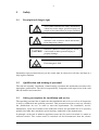
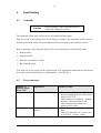
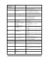
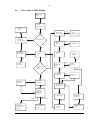
SERVICE-MANUAL
INDUCTION COOKERS
BASE-LINE/INSTALL-LINE/WOK-LINE
BH/BA 1500
BH/BA 1800
BH/BA 2300
BH/BA 2500
BH/BA 3000
BH/BA 3500
BH/IN 2500
SH/BA 3500
SH/BA 5000
SH/IN 3500
SH/IN 5000
SH/WO 3500
SH/WO 5000
SH/WO 8000
SH/WO/IN 3500
SH/WO/IN 5000
SH/WO/IN 8000
Freecall 1800 998 125
www.iceandoven.com
Ice And Oven | 1312 | Inducs Service Manual | Version 13-Aug-14
-1-
CONTENT
1
Safety .............................................................................................................................. 2
1.1
1.2
1.3
1.4
1.5
Description of danger signs ....................................................................................... 2
Qualification and training of personnel ...................................................................... 2
Safety prescriptions for installation and service ......................................................... 2
Unauthorized reconstruction and use of spare parts ................................................... 3
Improper operating methods ...................................................................................... 3
2
Technical information ................................................................................................... 4
3
Functioning .................................................................................................................... 6
3.1
3.2
3.3
4
Adjusting the performance rate.................................................................................. 6
Check of the temperature........................................................................................... 6
Overload current protection ....................................................................................... 6
Tests................................................................................................................................ 7
4.1 Pan material for induction cookers ............................................................................ 7
4.2 Pan detection ............................................................................................................. 7
4.3 Test with pans ........................................................................................................... 8
4.4 Test with metallic plates ............................................................................................ 8
4.5 Power rating .............................................................................................................. 8
4.6 Maximum rating ........................................................................................................ 8
4.7 Fan ............................................................................................................................ 9
4.8 Test of the components.............................................................................................. 9
4.8.1 Rectifier .............................................................................................................. 9
Transistor module (IGBT) ............................................................................................. 10
5
Maintenance/Service .................................................................................................... 11
6
Fault finding................................................................................................................. 12
6.1
6.2
6.3
7
Exchange of spare parts .............................................................................................. 16
7.1
7.2
7.3
8
To open the induction unit (base) ............................................................................ 16
To open the induction unit (install) .......................................................................... 16
Repair of spare parts................................................................................................ 17
Adjustment of process parameters .............................................................................. 18
8.1
8.2
8.3
8.4
9
Generally ................................................................................................................ 12
Error messages ........................................................................................................ 12
Flow chart to fault finding ....................................................................................... 15
How to initialize CU sensors by the short circuit plug ............................................. 18
Initialisation of the induction unit by PC/Laptop ..................................................... 19
Change of the parameters ........................................................................................ 19
Parameters for mains current and pan detector......................................................... 22
IR Interface .................................................................................................................. 24
9.1
Build-up of IR communication ................................................................................ 24
080417_Service manual Base, Wok- and Install-Line E
-2-
1
Safety
1.1
Description of danger signs
This symbol identifies the safety information
which may cause danger (personal injury) for
people at non-observance of proper operation.
This dangerous voltage warning symbol
indicates a risk of electric shock and hazards
from dangerous voltage.
CAUTION
Indicates a hazard or unsafe practice which
could result in minor personal injury or
property damage.
Electromagnetic field
Information signs mounted directly on the cooker must be observed at all times and kept in a
fully legible condition.
1.2
Qualification and training of personnel
The staff for assembly, installation, commissioning, operation and maintenance must have the
appropriate qualification. The field of responsibility, competence and supervision of the staff
must be defined and controlled.
1.3
Safety prescriptions for installation and service
The operating personnel has to make sure that installation and service as well as all inspection
is done by authorized and qualified personnel. This personnel must have read very carefully
the „Instructions for use“ in order to meet the requirements. For installation, service,
maintenance, repair and overhaul of the induction cookers, the personnel has to be specially
qualified and must have attended a special training, authorized by the manufacturer.
In principle, such work at induction appliances must only be carried out when it is under no
electrical tension. The cookers must be switched off and disconnected from the electric
080417_Service manual Base, Wok- and Install-Line E
-3-
connection. The installation of safety and protection must be re-installed after finishing the
work.
1.4
Unauthorized reconstruction and use of spare parts
Reconstruction of the cooker or changes to the cooker are not allowed. Contact the
manufacturer if you intend to do any changes to the cooker. To guarantee safety, use genuine
spare parts and accessories authorized by the manufacturer. The use of other components will
cancel any liability for the resulting consequences.
1.5
Improper operating methods
The operating reliability of the cookers can only be guaranteed with appropriate use of the
cooker. The limit values may be exceeded on no account.
080417_Service manual Base, Wok- and Install-Line E
-4-
2
Technical information
Modell BH/BA
Wattage kW
Current A
Power factor Cos φ
Discharge rate mA
∅ Coil mm
120 V/1 Ph
1.5/1.8
12.5/15
>0.95
4
190
208 V/1 Ph
2.5/3/3.5
12/14.5/17
>0.95
4
190
230 V/1 Ph
2.3/2.5/3/3.5
10/11/13/15
>0.95
4
190
240 V/1 Ph
2.5/3 /3.5
10/12.5/14.5
>0.95
4
190
Modell BH/IN
Wattage kW
Current A
Power factor Cos φ
Discharge rate mA
∅ Coil mm
208 V/1 Ph
2.5
12
>0.95
4
190
230 V/1 Ph
2.5
11
>0.95
4
190
240 V/1 Ph
2.5
10
>0.95
4
190
Modell SH/BA
Wattage kW
Current A
Power factor Cos φ
Discharge rate mA
∅ Coil mm
Modell SH/BA
Wattage kW
Current A
Power factor Cos φ
Discharge rate mA
∅ Coil mm
208 V/1 Ph
3.5
max. 16
>0.95
4
190
208 V/3 Ph
5
13.9
>0.95
4
190
230 V/1 Ph
3.5
15
>0.95
4
190
400 V/3 Ph
5
7.2
>0.95
4
190
240 V/1 Ph
3.5
14.5
>0.95
4
190
440 V/3 Ph
5
6.6
>0.95
4
190
Modell SH/IN
Wattage kW
Current A
Power factor Cos φ
Discharge rate mA
∅ Coil mm
Modell SH/IN
Wattage kW
Current A
Power factor Cos φ
Discharge rate mA
∅ Coil mm
208 V/1 Ph
3.5
max. 16
>0.95
4
190
208 V/3 Ph
5
13.9
>0.95
4
190
230 V/1 Ph
3.5
15
>0.95
4
190
400 V/3 Ph
5
7.2
>0.95
4
190
240 V/1 Ph
3.5
14.5
>0.95
4
190
440 V/3 Ph
5
6.6
>0.95
4
190
080417_Service manual Base, Wok- and Install-Line E
-5-
Modell SH/WO
Wattage kW
Current A
Power factor Cos φ
Discharge rate mA
∅ Coil mm
Modell SH/WO
Wattage kW
Current A
Power factor Cos φ
Discharge rate mA
∅ Coil mm
208 V/1 Ph
3.5
max. 16
>0.95
4
190
208 V/3 Ph
5
13.9
>0.95
4
190
230 V/1 Ph
3.5
15
>0.95
4
190
400 V/3 Ph
5/8
7.2/11.6
>0.95
4
190
240 V/1 Ph
3.5
14.5
>0.95
4
190
440 V/3 Ph
5
6.6
>0.95
4
190
Modell SH/WO/IN
Wattage kW
Current A
Power factor Cos φ
Discharge rate mA
∅ Coil mm
Modell SH/WO/IN
Wattage kW
Current A
Power factor Cos φ
Discharge rate mA
∅ Coil mm
208 V/1 Ph
3.5
max. 16
>0.95
4
190
208 V/3 Ph
5
13.9
>0.95
4
190
230 V/1 Ph
3.5
15
>0.95
4
190
400 V/3 Ph
5/8
7.2/11.6
>0.95
4
190
240 V/1 Ph
3.5
14.5
>0.95
4
190
440 V/3 Ph
5
6.6
>0.95
4
190
Max. tolerance of power supply
Frequency
Protection class
Min. diameter of pans
Max. ambient temperature: stockage
Max. ambient temperature: function
Max. relative humidity of air: stockage
Max. relative humidity of air: function
Nominal voltage +6/-10 %
50/60 Hz
IP X0
Approx. 12 cm/approx. 4.7“
-20 to 70ºC/-4 to +158ºF
+5 to 40ºC/41 to 104 ºF
10 to 90 %
30 to 90 %
080417_Service manual Base, Wok- and Install-Line E
-6-
3
Functioning
3.1
Adjusting the performance rate
The performance rate is adjusted by the potentiometer (control knob). The inductive
performance depends on the position of the potentiometer:
•
Position 1 = minimum power
•
Position 9 (resp. Position 12) = maximum power.
3.2
Check of the temperature
Induction coil
The temperature of the induction coil is checked by a temperature sensor. If the coil is heated
over the maximum temperature, the heating process is stopped. As soon as the coil has cooled
down, the Induction unit can be re-started. Turn the position of the kontrol knob on „0“ and
then on the required power level (see chapter 7.2 Error Messages).
Power board
The temperature of the heat sink is checked by a temperature sensor. As soon as the heat sink
is heated over 60ºC/140ºF, a cooling fan is started. A temperature of the heat sink of more
than 75ºC/167ºF will reduce automatically the power in order to keep the induction cooker
working under normal conditions. The internal temperature of the unit is supervised as well.
The power will be reduced when the temperature reaches 70°C/158°F. As soon as the
temperature reaches 80ºC/176°F the unit will stop working and show the error code E06 (see
chapter 7.2).
3.3
Overload current protection
When inappropriate pan material or magnetic objects are detected on the heating area, the
current in the induction coil may rise substantially. In order to protect the power board, the
coil current is checked. As soon as the current in the coil exceeds the tolerance, the generator
will cut out and there is no further active energy exchange. The unit can be re-started as soon
as normal working conditions are reached.
080417_Service manual Base, Wok- and Install-Line E
-7-
4
Tests
4.1
Pan material for induction cookers
When cooking with induction it is most important to use appropriate pan material. The bottom
of the pan is the element that closes the magnetic field generated by the induction coil. We
recommend to use only appropriate pan material.
In order to check your pan, make a test. You will need 1lt water of about 20ºC/68ºF. Heat up
the pan with maximum power and measure the time it takes until the water is boiling. Refer
and compare to the reference time given by INDUCS Ltd. (2,5kW approx. 240 sec., 3,5kW
approx. 140 sec., 5kW
approx. 80 sec., 8kW
approx. 60 sec.). This heating-up time
gives you information about the efficiency of the pan. Bad pans have considerably longer
heating-up times for the same quantity of water.
In order to find out whether the pan material is appropriate for induction, use a magnet. This
has to stick to the bottom of the pan. This test says nothing about the efficiency or the
material structure of the pan (it can be a bad induction pan).
4.2
Pan detection
The heating area is warmed up by the hot pan.
ATTENTION To avoid injuries (burnings) do not touch the
heating area.
This test shows whether the induction cooker is working well when pans with a small
diameter are used and if small metallic objects are heated-up on the heating area.
To do this test, you need the following material:
An appropriate pan with a bottom diameter of 12cm/4.7“ or two untreated round iron plates,
approximately 4mm/0.16“ thick:
•
iron plate 1:
diameter d = 12 cm/4.7“
•
iron plate 2:
diameter d = 7 cm/2.75“
080417_Service manual Base, Wok- and Install-Line E
-8-
4.3
Step
1
2
4.4
Step
1
2
4.5
Test with pans
Action
Put the pan in the middle of the heating
area
Push the pan until the edge of the pan is
in the middle of the heating area
Level
Result
1.......9 (12) Heat, the indicator lights
1.......9 (12) No heating, the indicator
does not light
Test with metallic plates
Action
Put the metallic plate 1 in the middle of
the heating area
Put the metallic plate 2 in the middle of
the heating area
Level
Result
1.......9 (12) Heat, the indicator lights
1.......9 (12) No heating, the indicator
does not light
Power rating
The heating area is warmed up by the hot pan.
ATTENTION To avoid injuries (burnings) do not touch the
heating area.
Step Action
1 Put the pan on the heating area until the
water boils
2 Reduce the power by turning the control
knob down slowly
4.6
Level
9 (12)
Result
Heat, water is boiling
(12) 9.......1 Heat rating reduces (water
does not boil anymore),
phase current reduces
Maximum rating
The heating area is warmed up by the hot pan.
ATTENTION To avoid injuries (burnings) do not touch the
heating area.
080417_Service manual Base, Wok- and Install-Line E
-9-
4.7
Fan
With this test, fan, fan controller as well as the degree of soiling are verified. At the beginning
of the test, the induction cooker should be cold. You need a pan with a bottom diameter of
>28 cm/11“.
Step
1
2
3
4
4.8
Action
Put a pan on the heating area and fill a
few litres of water in it
Measure the time until the fan starts
working
Go on cooking for about 30 minutes
Turn off the induction cooker
Level
9 (12)
9 (12)
9 (12)
0
Result
Heat
The fan should start working
in 6-8 minutes
The fan keeps working.
Test of the components
CAUTION The mains cable must be switched off.
4.8.1
Rectifier
The rectifier is fixed at the power board with four wires. These rectifier connections have to
be unsoldered for correct test results At first, you have to measure the forward voltage
between anode – cathode by means of the multimeter (please use only multimeters with diode
check as an additional function).
The forward voltage for this diode is about 0,5V in the direction A – C, in the opposite
direction there is no current flow.
080417_Service manual Base, Wok- and Install-Line E
-10-
In case one of the four diodes shows a short circuit or an interruption, the rectifier is defective
and has to be exchanged.
4.8.2
Transistor module (IGBT)
IRG40UD
G
E
C
The IGBT (Insulated Gate Bipolar Transistor) is fixed on the circuit board with three solder
connections.
The IGBT Transistor has as a supplementary protection an integrated recovery diode. At first,
we have to measure the on-state voltage of this diode. The forward voltage of this diode
should be about 0,5V.
In case the recovery diode shows a short circuit or an interruption, the IGBT transistor
is defective and has to be exchanged.
080417_Service manual Base, Wok- and Install-Line E
-11-
5
Maintenance/Service
Maintenance work may only be done by authorized personnel. Before starting the
maintenance work, the power supply must be turned off and the appliance must have cooled
down. The following maintenance works need to be carried out periodically. The longer and
more frequently the cooker is used, the more often the maintenance works have to be done.
Every cooker should be checked at least once a year.
Fan
The proper function of the cooker can only be guaranteed if the electronic unit is kept at
normal working temperature.
•
The air inlet and outlet slots must not be blocked or covered.
•
The air filter must not be blocked by dirt or grease.
•
The airducts must be free of dirt.
•
The air must circulate freely through the heat sink .
•
The fan is properly mounted.
•
The heat sinks are properly mounted.
Check Induction coil
•
Mechanical fixing (screws tightened)?
•
Coil adhesive (mounting o.k.)?
•
Ferrite (mounting o.k.)?
•
Copper coil (mounting o.k.)?
General check
•
Earth protection
•
Screwed connections
•
Cable insulation
•
Any kind of dirt or liquids that have entered the cooker must be cleaned out
•
Remove insects (if present)
080417_Service manual Base, Wok- and Install-Line E
-12-
6
Fault finding
6.1
Generally
Caution
Do not open the cooker while the power is
connected. Dangerous tension!
The induction cooker may only be serviced by authorized personnel.
Stop any work if the heating area (Ceran Glass) is broken. The induction cooker must be
switched off and the mains cable disconnected. Do not touch any parts inside the cooker.
Before replacing a part, check the wiring. Give special attention to the following faults:
•
Broken cables
•
Squeezed cables
•
Defective insolations of cables
•
Bad soldering joints
You must not do any repair on the circuit boards. The appropriate maintenance work should
be carried out after each repair (see „Maintenance“, and „Service“).
6.2
Error messages
Number of
flashing signals
Error code
3
Significance
Measures to take
Temperature heat sink 3)
a. Heat sink temperature too high– wait
until the temperature has cooled down
under 80ºC/176ºF
b. Check supply of cooling air – perhaps
blocked – check function of fan
c. Check temperature of heat sink –
replace power circuit
a. Temperature of the cooking surface too
high
b. Check CU measure coil – index value
at 20ºC/68ºF – approx. 5Ohm
-...-...-
4
-....-....-....-
Temperature cooking
surface 3)
080417_Service manual Base, Wok- and Install-Line E
-13-
Number of
flashing signals
Error code
5
-.....-.....-.....6
Signification
Measure to take
Error on power switch 3)
a. Check connection
b. Check power switch
c. Check whether the unit is next to a
source of heat as e. g. friteuse
d. Check whether hot air is taken in –
generator has no air exhaust system
a. Check cooking material in the pan
-......-......-......-
Temperature inside the unit
too high 3)
7
Empty cooking sensor 1)
-.......-.......-.......-
8
Sensor error 3)
-........-........-........-
12
13
17
Power reduction, heat sink
temperature 2)
Power reduction,
temperature of cooking
surface 2)
CU sensor 1
Warning temperature
CU sensor 1
overtemperature 3)
18
CU sensor 2
overtemperature 3)
19
CU sensor 2
warntemperature
20
Power reduction generator
inside temperature 2)
21
24
25
Heat sink sensor error 3)
Board temperatur sensor
error 3)
CU sensor 1 error 3)
26
CU Sensor 2 error 3)
27
28
a.
b.
c.
d.
a.
b.
a.
Check Cu sensor
Check heat sink sensor
Check RTCS-sensor
Check board sensor
Turn the power down
Check fan
Take pan off until cooking area has
cooled down
b. Wait until it has cooled down
c. Check coil
a. Temperature of the cooking field too
high
b. Check CU sensor 1, index value 5Ohm
at 25ºC
a. Temperature of the cooking field too
high
b. Check CU sensor 2, index value 5Ohm
at 25ºC.
a. Temperature of the cooking field too
high
b. Turn the power down
a. Check for heat sources around the
generator and remove them
b. Check air circulation
a. Contact Inducs AG
a. Exchange power unit
a. Check CU sensor 1 for short circuit or
discontinuation, index value 5Ohm at
25ºC.
a. Check CU sensor 2 for short circuit or
discontinuation, index value 5Ohm at
25ºC.
Empty cooking detector CU a. Check cooking material in the pan
sensor 1 1)
Empty cooking detector CU a. Check cooking material in the pan
sensor 2 1)
080417_Service manual Base, Wok- and Install-Line E
-14-
1)
The induction unit can only be restarted when the fault has been rectified (turn power rotary
knob „off“)
2)
The induction unit continues working.
3)
The induction unit does not heat..
Order of error message for error code 1-8:
The indicator lamp flashes for an interval of 0,6 sec. The following short flashes need to be
counted. This gives information about the error corresponding to the above mentioned code
system.
080417_Service manual Base, Wok- and Install-Line E
-15-
6.3
Flow chart to fault finding
Unit does not
work!
Check
mains supply
Replace
fuse
Yes
Short circuit
connection Poti?
Check fuse
of installation
and mains supply
No
No
Connection o.k?
Defect
Check
LED
O.k.
Yes
Check mains
plug and socket
Check
connection Poti
O.k.
Replace LED
O.k.
Dismount
unit
Connect
Unit
Replace
power board
Defect
Defect
Defect
Contact
electrician
Is there any
LED
indication?
No
Yes
Check fuse
T10A
Check
rectifier
O.k
O.k
Check electric
voltage DC
Error
Check fuse
T1A
O.k.
Error code in
IR mode ?
No
Is there any
error code ?
Yes
Yes
Check circuit
board (visually)
Error
Utilize error
code and go
ahead according to list
Check wiring
It works
Check IGBT
transistors
It does not work
Wrong
Unit works.
Continuous test for
about 10 min.
necessary
Replace power
board
Correct
wiring
080417_Service manual Base, Wok- and Install-Line E
Replace power
board
-16-
7
7.1
Exchange of spare parts
Caution
All spare parts and accessories may only be
changed by authorized personnel.
Caution
In order to guarantee safety use only genuine
spare parts and accessories from
INDUCS Ltd.. If other components are used
no liability is accepted.
Caution
The mains cable must be disconnected.
To open the induction unit (base)
•
Turn the induction unit over (upside down)
•
Remove M4x8 screws
•
Turn induction unit back to normal position
•
Lift cover, tip to the right side, stand it on its side
•
Remove coil carrier: remove the 2 stop nuts on the left
•
Remove M4 screws
•
Remove screws A1 and A2
•
Turn away coil carrier at the left
7.2
To open the induction unit (install)
•
Remove M4 screws on the right side
•
Lift cover with the glass
•
Remove M4 screws, remove coil carrier
•
Remove PT-sensor and coil connections
080417_Service manual Base, Wok- and Install-Line E
-17-
7.3
Repair of spare parts
Repair of spare parts and of whole units may only be effected by INDUCS Ltd. Therefore
check and replace only parts described in this service manual.
In case you should repair parts, please describe exactly the faults and give information about
the history of the unit, for example new installation, changements done next to the induction
cooker or to other units supplied by the same network.
In order to save transport charges, do not return defective parts such as temperature sensors,
rectifier, transistor modules, interrupters. Such parts can be disposed correctly on place.
080417_Service manual Base, Wok- and Install-Line E
-18-
8
Adjustment of process parameters
The induction unit (excluding WOK-units) with new Cu sensors can be adjusted. This can be
done either by means of the short circuit plug Poti-LED art. nr. 94900096 or by PC/Laptop. In
addition, the pan detection and the performance can be adjusted by the hyperterminal program
of the PC/Laptop. Exact information to the use of the hyperterminal program is given in chapter
9 „IR interface“.
8.1
How to initialize CU sensors by the short circuit plug
If only the CU sensor is exchanged, the new CU sensor can be initialized by means of the short
circuit plug Poti-LED. For this, you will not need the PC/Laptop. The pan detection and the
performance will not have to be changed.
Prozedure of initialization:
-
The cooking area has to be devoid of any items
-
Surrounding temperature 25ºC (+/-3ºC)
-
Disconnect the induction unit from the mains supply
-
Put short circuit plug Poti-LED into the power print
-
Connect the induction unit to the mains supply
-
The CU sensors will now be initialized automatically
-
After successful initialization, the green LED on the CPU-print will illuminate.
-
In case the system will find an error during initialization, the red LED will illuminate
-
Disconnect the induction unit from the mains supply
-
Check the CU sensors at the plug by means of the Ohmmeter
-
Re-start the procedure of initialization
-
Disconnect the unit from the mains supply
-
Remove the short circuit plug Poti-LED
080417_Service manual Base, Wok- and Install-Line E
-19-
8.2
Initialisation of the induction unit by PC/Laptop
The initialization of the CU sensors as well as the adjustments of pan detection and
performance can be done by means of the hyperterminal program. You will find exact
information for the handling of the hyperterminal program in chapter 9 „IR interface“.
IMPORTANT! Pay special attention whether you receive feedback signal from the PC/Laptop
after every changement. This will be the sign that the changement has been accepted.
12345
Entry to the mode of adjustment (password)
;
Initialize Cu sensor (temperature of the coil ca. 25°C) (excluding WOK)
N
Increase the mains current limit (+)
n
Decrease the mains current limit(-)
"
Save the limit of the mains current
T
Increment pan detection (+)
t
Decrement pan detection (-)
=
Save pan detection
-?
Leave the mode of adjustment
.
State software version
8.3
Change of the parameters
1. Connect the RS232 connection cable to the PC/Laptop and straighten the IR-box to the left
lower corner of the ceran glass.
2. Start HT2400 (see chapter 9) and turn unit on!
3. By input of „12345“ the mode of adjustment is started. The following message appears on
the hyperterminal program:
IR= On
WELCOME REPAIRMEN
4. Not valid for WOK. The parameters on the CPU can now be changed! The unit temperature
and the surrounding temperature have to be 25°C (+/-4°C). Press the key „;“. On the
console appears the message „please confirm“. Press the key „;“ again. The CU sensor will
now be initialized to 25°C. The following message appears on the hyperterminal program:
save CU sensor : 25ºC
080417_Service manual Base, Wok- and Install-Line E
-20-
5. Set the limit of the mains current (see mains current parameters in chapter 8.2):
N
N
increase the limit of the mains current (+)
decrease the limit of the mains current (-)
The following message appears on the hyperterminal program:
linecurrent limit= .......
6. Save the limit of the mains current with the key „""! On the console appears the message
„please confirm“. Press the key „"" again. The following message appears on the monitor:
save linecurrent limit: .......
7. Set the pan detector (see pan detector parameters in chapter 8.2):
T
T
increase pan detector (+)
decrease pan detector (-)
The following message appears on the monitor:
pan detection limit= .......
8. Save the pan detector with the key „=“.On the console appears the message „please
confirm“. Press the key „=“ again. The following message appears on the monitor:
save pan detection limit: .......
9. By input „-?“ the mode of adjustment will be left. The following message appears on the
monitor:
see you again!
10. The mode of adjustment has a time-out function. After 10 minutes the mode of adjustment
will be left automatically.
The adjustments are now finished and it is not possible to make any other adjustments.
Otherwise you have to start at the beginning!
080417_Service manual Base, Wok- and Install-Line E
-21-
Different information about the unit is shown in the adjusting mode. The following parameters
can be read:
Output on the hyperterminal program:
1: KK:58 CU1:22 CU2:22 B:33 --- --- F:20080
1: KK:58 CU1:22 CU2:24 B:33 --- --- F:20080
1: KK:57 CU1:22 CU2:24 B:33 --- --- F:20080
1: KK:57 CU1:22 CU2:24 B:33 --- --- F:20080
Meaning:
CU sensor 2 – outside
temperature of the coil
Heat sink
temperature
Error message
1: KK:58 CU1:22 CU2:22 B:33 --- --- F:20080
Active
field
Board temperature
CU sensor 1 – inside
temperature of the coil
Frequency
Status message
The fan will be activated at a heat sink temperature of 60ºC.
080417_Service manual Base, Wok- and Install-Line E
-22-
8.4
Parameters for mains current and pan detector
Article Nr.
Unit
Mains current
Pan detector
BH/BA 1500, 120VAC, 1N, 1,5kW
160
29
99560102
BH/BA 1800, 120VAC, 1N, 1,8kW
187
21
99560103
BH/BA 2500, 208VAC, 1N, 2,5kW
153
23
99560104
BH/BA 2500, 230VAC, 1N, 2,5kW
140
27
99560105
BH/BA 2500, 240VAC, 1N, 2,5kW
99560106
BH/BA 3000, 208VAC, 1N, 3kW
180
26
99560107
BH/BA 3000, 230VAC, 1N, 3kW
163
28
99560108
BH/BA 3000, 240VAC, 1N, 3kW
99560109
BH/BA 3500, 208VAC, 1N, 3,5kW
192
26
99560110
BH/BA 3500, 230VAC, 1N, 3,5kW
187
28
99560111
BH/BA 3500, 240VAC, 1N, 3,5kW
99560112
BH/BA 2300, 230VAC, 1N, 2,3kW
130
27
980000
BH/IN1500, 120VAC, 1N, 1.5kW
162
33
-
BH/IN1800, 120VAC, 1N, 1.8kW
187
33
99580001
BH/IN 2500, 208VAC, 1N, 2,5kW
153
33
99580002
BH/IN 2500, 230VAC, 1N, 2,5kW
140
36
99580003
BH/IN 2500, 240VAC, 1N, 2,5kW
99560004
SH/BA 3500, 208VAC, 1N, 3,5kW
192
36
99560005
SH/BA 3500, 230VAC, 1N, 3,5kW
192
35
99560006
SH/BA 3500, 240VAC, 1N, 3,5kW
185
34
99560007
SH/BA 5000, 208VAC, 3N, 5kW
167
21
99560008
SH/BA 5000, 400VAC, 3N, 5kW
90
12
99560009
SH/BA 5000, 440VAC, 3N, 5kW
99580004
SH/IN 3500, 208VAC, 1N, 3,5kW
192
36
99580005
SH/IN 3500, 230VAC, 1N, 3,5kW
192
35
99580006
SH/IN 3500, 240VAC, 1N, 3,5kW
185
34
99580007
SH/IN 5000, 208VAC, 3N, 5kW
167
21
99580008
SH/IN 5000, 400VAC, 3N, 5kW
90
12
99580009
SH/IN 5000, 440VAC, 3N, 5kW
080417_Service manual Base, Wok- and Install-Line E
-23-
Article Nr.
Unit
Mains current
Pan detector
99570001
SH/WO 3500, 208VAC, 1N, 3,5kW
192
29
99570002
SH/WO 3500, 230VAC, 1N, 3,5kW
192
31
99570003
SH/WO 3500, 240VAC, 1N, 3,5kW
185
41
99570004
SH/WO 5000, 208VAC, 3N, 5kW
167
23
99570005
SH/WO 5000, 400VAC, 3N, 5kW
90
11
99570006
SH/WO 5000, 440VAC, 3N, 5kW
78
10
99570008
SH/WO 8000, 400VAC, 3N, 8kW
141
15
99580016
SH/WO/IN 3500, 208VAC, 1N, 3,5kW
192
29
99580017
SH/WO/IN 3500, 230VAC, 1N, 3,5kW
192
31
99580018
SH/WO/IN 3500, 240VAC, 1N, 3,5kW
185
41
99580019
SH/WO/IN 5000, 208VAC, 3N, 5kW
167
23
99580020
SH/WO/IN 5000, 400VAC, 3N, 5kW
90
11
99580021
SH/WO/IN 5000, 440VAC, 3N, 5kW
78
10
99580025
SH/WO/IN 8000, 400VAC, 3N, 8kW
141
15
080417_Service manual Base, Wok- and Install-Line E
-24-
9
IR Interface
9.1
Build-up of IR communication
To build-up the IR communication, you need the software Hyper Terminal which is usually
already available in Windows under Start =>Program=>Accessories => Hyperterminal.
Prior to the first use, Hyperterminal should be configurated properly. INDUCS service needs
the following settings:
Connect the IR box and bring it into line to the IR sensor on the generator.
Start Hyperterminal and give an access name, e. g. IR2400.ht
Select the communication via COM1 (or where your IR box has been connected).
080417_Service manual Base, Wok- and Install-Line E
-25-
Select the following settings: 2400 Bits/sec., 8 Databits, no parity, 1 Stop bit, Hardware
protocol
These adjustments will be saved under the access name IR2400.ht.
080417_Service manual Base, Wok- and Install-Line E