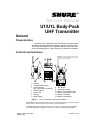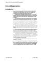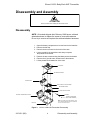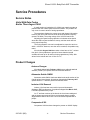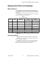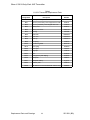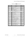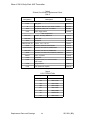
1
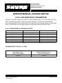
Shure Incorporated
222 Hartrey Avenue
Evanston IL 60202-3696 U.S.A.
UHF Wireless System
SERVICE MANUAL CHANGE NOTICE
U1/U1L UHF BODY-PACK TRANSMITTER
Changes and corrections have been made to the Service Manual for the U1/U1L UHF Body-Pack Transmitter. These changes will make it easier to repair the transmitters. To update your Service Manual,
remove the pages identified in the tables below and replace them with the pages attached to this Change
Notice. Note that there are no changes to pages not specifically identified in the tables below.
U1/U1L SERVICE MANUAL REVISION HISTORY
Release
Part Number
Date Code
Original
25A1021
QE
Revision 1
25B1021
SA
Revision 2
25C1021
TD
Revision 3
25C1021
AG
Revision 4
25C1021
BF
Revision 5
25C1021
BG
CHANGES EFFECTIVE JULY 12, 2002
REMOVE
these pages from the
U1/U1L Service Manual
21 to 25
E
2000, Shure Incorporated
25–1021–2 (BG)
INSERT
these Revised pages into the
U1/U1L Service Manual
21 to 25
Printed in U.S.A.
Service Manual
U1/U1L Body-Pack
UHF Transmitter
General
Characteristics
The Shure U1/U1L Body-Pack UHF Transmitter is a microprocessorcontrolled body-pack transmitter operating in the UHF frequency range.
This product is intended for use in high-end installed sound, rental, and
concert sound applications. Different frequency variations are available.
Controls and Indicators
1
3
4
5
NOTE: All models shipped after February 1999
have a soldered attached antenna to replace the
screw-on removable antenna. .
1
2
7
8
O O
N FF
9
6
10
11
12
1. Antenna
2. Programmable Display
3. Input Connector
(U1L uses LEMO connectors)
4. ON/OFF Switch
5. On/Off LED
6. Belt Clip
7. MODE Button
13
8.
9.
10.
11.
12.
13.
SET Button
Audio Gain Control
Battery Cover Release Tabs
Battery Compartment Cover
Battery Fuel Gauge
Battery Compartment
Figure 1. U1/UL Transmitter Controls and Indicators
Service Note: Shure recommends that all service procedures be performed by a Factory-Authorized
Service Center or that the product be returned directly to Shure Brothers Inc.
Licensing: Operation may require a user license. Frequency or power-output modifications
may violate this product’s approvals. Contact your country’s communications authorities.
E
1999, Shure Incorporated
25B1021 (BG)
Printed in U.S.A.
Shure U1/U1L Body-Pack UHF Transmitter
Circuit Description
Audio Section
Audio enters L201, an inductor that is used as an rf choke. The
signal enters a 6 dB pad made up of R203, R204, C204, and C206.
The signal is ac-coupled through C205 into a 40 dB (30 dB for JB
frequencies) user-adjustable gain stage around U201A.
This gain stage is externally accessible to the user. C201, C202,
and C207 protect the pre-amplifier and bias circuits from rf interference.
R205 and R207 set up a half-supply bias, and R206 sets the ac input
impedance.
The amplified audio signal is then passed through a pre-emphasis
network before entering the compression stage. R208, R211, and C211
set up two corners for the pre-emphasis network. The pre-emphasis
network boosts the high frequencies before transmission and helps set
the hinge point (0 dB gain) of the compandor. The network feeds NE575
compandor U203, which utilizes an external amplifier U202B. The compandor performs 2:1 logarithmic compression of the audio signal.
Transistors Q201 and Q202, along with crystal Y202, form the tone key
oscillator circuit, which provides a stable, continuous 32.768 kHz sine wave.
Transistor Q204 buffers the tone key signal before it is added to the audio
signal.
The tone key signal is used in the receiver to provide audio output only
when the tone key signal is present in the transmitted signal. Therefore, if
the tone key or the transmitter is turned off, the receiver will be muted.
Q203 acts as a switch for toggling the tone key on and off. It is controlled
via the microprocessor. R224 allows the tone key amplitude level to be set.
The tone key circuit is powered by U208B, which is a dc amplifier
that multiplies the 3 V battery voltage to 4.5 V (gain = 1.5). As the battery
voltage drops, the tone key supply voltage also drops, which decreases
oscillator amplitude. The tone key amplitude is used by the receiver
to indicate transmitter battery strength.
The tone key feature indicates battery level at the receiver. It is not
available on JB models.
The tone key signal, along with the processed audio signal, is fed to
summing amplifier U202A. Resistors R232 and R233 set up a half-supply
bias. Resistor R231, located at the output of the summing amplifier, prevents spurious oscillations from the operational amplifier. After passing
through ac-coupling capacitor C232, the signal is fed to the rf module.
Circuit Description
2
25C1021 (BG)
Shure U1/U1L Body-Pack UHF Transmitter
Rf Section
Processed audio enters R243, an internal potentiometer adjusted for
45 kHz deviation (100% modulation) with a –7.2 dBV, 1 kHz tone, at the
output of the front audio stage (pin 1 of U201). On JB models, R243 is
adjusted for 5 kHz deviation with –63.2 dBV, 1 kHz tone, at the input to
the transmitter.
The audio is then fed to the tuning voltage pin of the voltage controlled
oscillator (VCO) and modulates the carrier directly. The use of a phase
locked-loop (PLL) frequency synthesized system eliminates the need for
multiplier stages, resulting in a much higher degree of spectral purity. The
VCO is shielded against interference from external rf fields. Regulated
+5 Vdc power from the dc-to-dc converter ensures frequency stability,
even if the battery voltage changes.
At the output of VCO U205, the rf signal splits into two paths. The
output of the VCO is coupled by C244 to the frequency control pin of
synthesizer U204. The synthesizer’s internal circuitry divides the signal
as necessary to reach the desired reference frequency.
The synthesizer contains a quartz-controlled reference oscillator
circuit, including a 4.0 MHz crystal (Y201), that is adjusted by means of
trimmer capacitor C239.
The transmitter output frequency is user-selectable. Frequency
selection is made via microprocessor U103, which interfaces with the
user by means of the mode/select switches. The output of the synthesizer is a series of pulses that are integrated by a passive loop filter (R238,
C245, R240, C266, C267, R239, and C247) to produce a control voltage
signal. The control voltage signal is then connected to the VCO through
amplifier U210A, which is used to isolate the PLL filter from the audio
modulation signals.
The VCO output is also coupled to an rf power amplifier through a
resistive pad consisting of R254, R255, R256, R257, and an LC matching network containing C261, L209, and C248. The rf power amplifier,
dual gate MESFET Q208, is fixed-tuned and configured as a common
source device.
Amplifier stability is obtained through resistive loading on the input,
R247. The output of Q208 contains a low-pass matching network (L206)
and an LC-type low-pass filter (LP206), which provide a high degree of
spectral purity. The output of the low-pass filter feeds a microwave isolator that reduces the production of reverse third-order intermodulation
products.
The transmitter is capable of delivering a maximum of +10 dBm
(10 mW) to the 50 Ω antenna. During transmitter power-up and frequency
selection, rf power is muted by bringing the base of Q209 high. This provides approximately 45 dB rf attenuation until the PLL has locked. The
transmitter rf is then unmuted by bringing the base of Q209 low. During
transmitter power off conditions, voltage is first removed from the VCO by
bringing the base of Q207 high. In this way, the transmitter carrier signal is
not allowed to drift off frequency during power on or power off conditions.
25C1021 (BG)
3
Circuit Description
Shure U1/U1L Body-Pack UHF Transmitter
Transmitter Display Board
The display board consists of the following circuitry blocks.
Microcontroller Section
The microcontroller section consists of microcontroller U103 and the
liquid crystal display (LCD). The microcontroller has an on-board liquid
crystal display (LCD) driver. R111, R113, and R114 supply the microcontroller with the LCD drive voltage for a four-plex drive. The LCD indicates
the UHF frequency group and channel. The LCD also has a battery fuel
gauge. A 4.000 MHz oscillator, Y101, provides the operating frequency to
the microcontroller. The oscillator circuit includes C107, C108, R102, and
R103, which along with Y101, U106, R112, and C112, form the reset circuit. U106 is the reset integrated circuit (IC) that resets the U103 microcontroller if the 5 V normal operating voltage falls below 3.5 V. R107 is
the pull-up resistor for the U103 programming voltage pin.
Memory Section
The memory section consists of U101, a non-volatile EEPRAM,
that stores current transmitter settings and the mapping of compatible
groups and channels.
Battery Management Section
The battery management section consists of comparator U102. It is
used to measure the effective battery voltage, with reference to +5 V, by
measuring the time used to charge a capacitor to a reference threshold
of 0.1 Vdc ± 0.01 Vdc. The battery is checked approximately every 5
seconds. Comparator U102 alternately charges C106 with +5 V reference voltage, then the battery voltage (PLUS signal, test point I109).
User Interface Section
The user interface section consists of the Power, Mode, and Set
switches. The status of each switch function is indicated on the LCD.
Power Supply Section
The U105 dc-to-dc converter provides the transmitter with regulated
+5 V derived from two AA batteries. Power MOSFET Q101 provides
reverse battery protection. Q103, R118, R286, and C124 control the
soft start and reset of dc-to-dc converter following battery voltage drops.
Circuit Description
4
25C1021 (BG)
Shure U1/U1L Body-Pack UHF Transmitter
Preliminary Tests
Test Component Locations
ABCD
MC68H
*
*Shorted with a
0 Ω resistor on F
board versions
and later.
Digital Display Board,
Side 1
Digital Display Board,
Side 2
*
*On F
board
versions
and later.
*On F
board
versions
and later.
* *
Rf-Audio Board,
Side 2
Rf-Audio Board,
Side 1
Mic-Jack Board,
LEMO 4-Pin,
Mic-Jack Board,
TINI Q-G 4-Pin,
Figure 2. Test Component Locations
25C1021 (BG)
5
Preliminary Tests
Shure U1/U1L Body-Pack UHF Transmitter
Listening Test
Before completely disassembling the transmitter, operate it to determine whether it is functioning normally and try to duplicate the reported
malfunction. Refer to the User Guide for operating instructions, troubleshooting, and specifications.
Review any customer complaint or request, and focus the listening
test on any reported problem. The following, more extensive, functional
tests require partial disassembly.
Functional Tests
Refer to the Disassembly section to partially disassemble the
transmitter for the following functional tests.
Use dc blocks at all rf outputs to protect test equipment.
Test Setup
1. Use a U4 receiver for the following functional tests.
2. Dc voltages are present at most rf test points. Use dc blocks
to protect the test equipment, if necessary.
3. Connect the (+) power supply terminal through a milliammeter
to the (+) contact on the battery nest, and the (–) power supply
terminal to (–) the contact on the battery nest.
4. Connect a dc voltmeter across the power supply and set the
power supply for +3 Vdc..
5. Connect the audio generator to the mic-jack board either via the
TINI QG connector, or the LEMO connector to BNC cable,
depending on mic style.
Rf Power
1. Attach a U4 antenna to the spectrum analyzer.
2. Turn the U1 on and hold it very close to the antenna. Move the
U1 up and down to maximize power on the spectrum analyzer.
3. Verify that output power is greater than 3 dBm.
Current Drain
1. Apply 3.0 Vdc to the battery terminals.
2. Verify that the current drain is less than 110 mA.
Preliminary Tests
6
25C1021 (BG)
Shure U1/U1L Body-Pack UHF Transmitter
Frequency Response
If the U1 has an attenuator switch on the back of the unit,
it should be set to –6 dB for the following tests (versions G or later).
Values between board versions may vary slightly; the following values
are typical values.
1. With the transmitter set to minimum gain, apply 200 mVrms
at 1 kHz to its input.
2. Connect the audio analyzer’s input to the unbalanced output of
the U4 receiver.
3. Make sure the receiver volume control is set to maximum.
4. With respect to the 1 kHz level, measure –8.22 dBu ± 2 dB.
5. Change the frequency to 100 Hz. Verify that the measurement
from the U4 unbalanced output is within ± 2 dB with respect to
the 1 kHz level.
6. Change the frequency to 10 kHz. Verify that the measurement
from the U4 unbalanced output is within ± 2 dB with respect to
the 1 kHz level.
25C1021 (BG)
7
Preliminary Tests
Shure U1/U1L Body-Pack UHF Transmitter
Notes
This page intentionally left blank.
Notes
8
25C1021 (BG)
Shure U1/U1L Body-Pack UHF Transmitter
Disassembly and Assembly
ATTENTION
Observe precautions when handling this static-sensitive device.
Disassembly
NOTE: All models shipped after February 1999 have a soldered
attached antenna to replace the screw-on removable antenna.
Do not try to remove and replace the soldered attached antennas.
1.
2.
3.
4.
Open the battery compartment cover and remove the batteries.
Remove the belt clip.
Remove the two screws from the back of the case.
Lift the top half of the transmitter case away to expose
the printed circuit boards.
5. Remove the two screws securing the battery nest to the chassis.
6. Remove the rf ground screw, located next to the antenna.
7. Lift the printed circuit boards out of the case.
TOP COVER
RF SHIELDING GASKET
BATTERY NEST
DIGITAL DISPLAY CIRCUIT BOARD
RF GROUND SCREW
RF-AUDIO CIRCUIT BOARD
ANTENNA
BATTERY COMPARTMENT COVER
CONDUCTIVE WASHER
(SLIPS OVER ANTENNA)
NOTE: All models shipped after February 1999
have a soldered attached antenna to replace the
screw-on removable antenna. .
BELT CLIP
Figure 3. U1/U1L Hand-Held Transmitter Disassembly
25C1021 (BG)
9
Disassembly and Assembly
Shure U1/U1L Body-Pack UHF Transmitter
Reassembly
After completing all repairs, replace the antenna. Then place the
circuit boards back in the case, making sure the multi-pin connectors on
the boards mate. Reassemble the transmitter by performing the steps of
the disassembly procedure in reverse order.
Disassembly and Assembly
10
25C1021 (BG)
Shure U1/U1L Body-Pack UHF Transmitter
Service Procedures
Service Notes
Units With Date Codes
Earlier Than August 1996
A small number of synthesizer ICs (U204) can experience start-up
problems with the 4 MHz crystal reference oscillator. The problem will
only occur for certain values of tuning capacitance.
The transmitter displays the correct group and channel information.
However, the carrier will have moved to its lowest possible frequency
(around 750 MHz). The tuning voltage of the VCO will read 0 Vdc.
Adjusting the crystal’s tuning capacitor to its lowest value should
cause the 4 MHz crystal oscillator to start up, and the carrier will lock
to the proper frequency.
The tuning capacitor can now be readjusted to center the carrier to
within ± 1000 kHz. However, once the unit is turned off, the problem may
return.
All units with August 1996 date codes or later have a 10 kΩ resistor
from pin 2 of the synthesizer to ground to insure that the internal
oscillator will start up for all values of tuning capacitance (C239). Safe
values for the resistor are from 16.8 to 33.2 kΩ.
Product Changes
Antenna Changes
All models shipped after February 1999 have a soldered attached
antenna (70A8017) to replace screw-on removable antenna.
Attenuator Switch SW201
Attenuator switch SW201 has been added to the audio section of the
rf-audio printed circuit board. All products shipped after February 1997
(board versions “F” and later) should include this switch.
Inductor L104 Removal
Inductor L104 has been removed for improved electrostatic
discharge (ESD) performance. On products shipped after March 1997,
L104 was replaced with a jumper.
On “F” and later versions of the board, the circuit was redesigned
and the jumper was removed. Shure recommends that any product
shipped before March 1997 have L104 removed and replaced with a
jumper.
Comparator U102
Comparator U102 has been changed to prevent an “88 88” display.
25C1021 (BG)
11
Service Procedures
Shure U1/U1L Body-Pack UHF Transmitter
Antenna Replacement
NOTE: All models shipped after February 1999 have
a soldered attached antenna to replace the screw-on
removable antenna. Do not try to remove and replace
the soldered attached antennas.
The top printed circuit board (pcb) is connected to the bottom pcb by
a multi-pin connector. Two wires also lead to the battery connector and a
three-wire flat cable that connects the pcbs to the microphone jack.
Handle the pcbs with care to avoid damaging these connections.
1. Open the battery compartment cover and remove the batteries.
2. Remove the belt clip.
3. Remove the two screws from the back of the case.
4. Lift the top half of the transmitter case away to expose the pcbs.
5. Remove the single screw visible next to the antenna connector.
6. Use the antenna to gently lift up both pcbs far enough so that the
antenna assembly clears the case, or remove the top pcb to gain
better access to the bottom pcb.
7. Remove the antenna by unscrewing it from the connector.
Make sure that the washer on the antenna clears the case.
8. Install the new antenna by screwing it onto the connector. If
necessary, replace the conductive rubber gasket at the base
of the antenna.
9. Return the pcbs to their original position.
10. Reinstall the single screw next to the antenna connector.
11. Perform these steps in reverse order to reassemble the unit.
Service Procedures
12
25C1021 (BG)
Shure U1/U1L Body-Pack UHF Transmitter
Measurement Reference
dBu is a measure of voltage, and dBm is a measure of power.
For example, the HP8903 should be labeled dBu instead of dBm
because it is a voltage measurement. These two terms are often used
interchangeably even though they have different meanings.
Audio levels in dBu are marked as dBm on the HP8903.
dB Conversion Chart
0 dBV = 2.2 dBu
0 dBu = 0 dBm, assuming the load = 600 Ω
Test Equipment
Most test equipment needed is described in the Shure Wireless
Service Equipment Manual. The following test equipment (or approved
equivalent) is also needed.
Table 1
Test Equipment
Equipment Type
Model
Audio analyzer
*Hewlett-Packard 8903B
Digital multimeter
Fluke 87
Interconnect Cable
Shure PT1843
BNC (Male) Cables (2)
Shure PT1838A
DC Blocker
Shure PT1838W
BNC (Female) to 1/4-inch Phone Plug Adapter
Shure PT1838C
20 dB Attenuator
Shure PT1838T
BNC to QG Cable
Shure PT1825
BNC to LEMO Cable
Shure PT1878
BNC (Female) to SMC (Female) Adapter
Shure PT1838S
BNC (Female) to SMC (Female) Adapter
Shure PT1838S
Test Cable, Japan Version
Shure PT1838–AF
Adapter, Japan Version
Shure PT1838–AJ
BNC (Male) to RG–174 Cable, unterminated
Shure PT1824
Frequency counter
Hewlett-Packard 53181A
Rf signal generator
Hewlett-Packard 8656B
Spectrum analyzer
Hewlett-Packard 8590L
Shure U4S receiver
Shure U4S
*Audio levels in dBu are marked as dBm on the HP8903B.
Printed Circuit Board Interconnecting Cable
This cable is provided with the standard test equipment and is used
to connect U1 circuit boards that have been removed from the case for
servicing. It is made from two custom Shure printed circuit boards, a fourinch, 11-wire ribbon cable, and one male (Shure 170A07) and one
female (Shure 170A08) surface-mount connector. Note that the SMC
connectors face in opposite directions.
Female SMC connector
Male SMC connector
(on back side)
Figure 4. Printed Circuit Board Interconnecting Cable
25C1021 (BG)
13
Service Procedures
Shure U1/U1L Body-Pack UHF Transmitter
Rf Alignment
FREQUENCY COUNTER
CH 2
CH 1
J3
U1 Transmitter
Frequency Counter
Power (S103): ON
Connect CH2: J3
Gain (R201): For JB models:
set to maximum
Figure 5. Alignment Test Set–Up
Rf Alignment Set-Up
1. Proper adaptors should be used to connect the test equipment.
2. Use RG58 or other low-loss 50 Ω cables for all rf connections.
3. Include the insertion loss of the cables and connectors in
rf conductive power measurements.
4. Connect the rf–audio board to the digital board through
board interconnects J104 and J200.
5. On all models except JB, audio GAIN potentiometer R201 does
not need to be preset to any position. On JB models, R201
GAIN should be set to maximum.
6. All rf measurements should be made from the antenna output
connection, the 50Ω SMC connector on PCB versions “G” and
earlier or through the P1824 test cable on PCB versions “H” and
later. For JB models with SMT rf test connector, use PT1838–AF
with PT1838–AJ.
Rf Alignment
1. Slide the ON/OFF switch (S103) to the ON position.
2. Connect the transmitter to the frequency counter via J3.
3. Determine the transmitter operating frequency by comparing the
Group and Channel information on the LCD to the tables in the
User Guide and User’s Guide Supplements.
4. Adjust variable capacitor C239 until the frequency counter measurement matches the desired operating frequency, ±1 kHz.
Service Procedures
14
25C1021 (BG)
Shure U1/U1L Body-Pack UHF Transmitter
Power Output Measurement
The output power measurement ensures that the output signal is
strong enough for sufficient range when the system is in use. The output
power measurement also verifies that the output power is not above the
specified maximum level, to ensure compliance with regulatory agencies’
standards.
SPECTRUM ANALYZER
U1 Transmitter
Spectrum Analyzer
Power: ON
Peak search: ON
Signal track: ON
Marker: ON
Figure 6. U1 Power Output Measurement Test Set-Up
1. Rf output power is not adjustable. Use RG58 or any other low
loss 50 Ω cables for all rf connections.
2. Include the insertion loss of the cables and connectors in
rf conductive power measurements.
3. Using the spectrum analyzer, verify output power is at least
+8 dBm. JB models must be at least +8 dBm and cannot exceed
+10 dBm.
25C1021 (BG)
15
Service Procedures
Shure U1/U1L Body-Pack UHF Transmitter
Audio Alignment
Deviation Reference Voltage
NOTE: DC VOLTAGES ARE PRESENT
AT MOST RF TEST POINTS. USE A
DC BLOCK ON THE RF SIGNAL
GENERATOR TO PROTECT
TEST EQUIPMENT.
S201
TONE-KEY
SWITCH
U4 RECEIVER
DC BLOCK
AUDIO ANALYZER
RF SIGNAL GENERATOR
U4 Receiver
Audio Analyzer
Output: Unbalanced
Gain: Maximum
Squelch: Mid
Tone Key (S201): OFF
Measurement: AC level
Filters:
Low-Pass (30 kHz): ON
Rf Signal Generator
INT: FM
INT: 1 kHz
Output Amplitude:
–50 dBm
High-Pass (400 Hz): ON
Figure 7. Deviation Reference Voltage Test Set-Up, Using a U4 Receiver
1. The U1 transmitter should be turned OFF for this procedure.
2. Connect the rf signal generator to antenna A or B on a U4
receiver. Make sure the dc block is on the rf signal generator.
3. Set the rf signal generator to the same frequency as the
U1 transmitter.
4. Set rf signal generator modulation to 1 kHz and set the deviation
to 45 kHz for UA, UB, MA, MB, MC, and MD models, 40 kHz for
KK models, and 5 kHz for II models.
5. Set the output amplitude of the rf signal generator to –50 dBm.
6. Turn the U4 receiver ON and set the tone key switch (S201)
inside the U4 receiver to the OFF position. This will disable the
receiver tone key function.
7. Connect the audio analyzer to the unbalanced output of the U4
receiver. The voltage should be 4.2 ± 0.5 dBu (1.26 ± 0.07 V) for
UA, MA, MB, MC, MD, and KK models, and –26.2 ± 0.5 dBu for
II models.
Note the voltage obtained; it is the deviation reference voltage.
8. Disconnect the rf signal generator from the U4 receiver and
return the tone key switch (S201) to the ON position.
Service Procedures
16
25C1021 (BG)
Shure U1/U1L Body-Pack UHF Transmitter
Deviation Reference Voltage Adjustment
U4 RECEIVER
20 dB PAD
DC BLOCK
AUDIO ANALYZER
NOTE: DC VOLTAGES ARE PRESENT
AT MOST RF TEST POINTS. USE A
DC BLOCK ON THE RF SIGNAL
GENERATOR TO PROTECT
TEST EQUIPMENT.
U1 Transmitter
Power: +3 Vdc
Audio Analyzer
Measurement: AC level
Gain: Minimum; for JB models,
set to MAX
Output: 1 kHz
Filters:
Low-Pass (30 kHz): ON
High-Pass (400 Hz): ON
Figure 8. Deviation Reference Voltage Adjustment Test Set-Up
1. The U1 transmitter should be turned ON for this procedure.
2. Turn the rf signal generator OFF for this procedure.
3. For G and later board versions, adjust the audio analyzer for 1
kHz to get a level of –5.0 dBu (436 mV) at pin 7 of U201.
4. For F or earlier board versions, adjust the audio analyzer for
1 kHz to get a level of –5.0 dBu (436 mV) at pin 1 of U201.
5. On JB models, adjust the audio analyzer for 1 kHz to –61.0 dBu
at the input connector.
6. Connect the transmitter rf output to a U4 antenna connector
through a dc block and a 20 dB pad.
7. Connect the U4 unbalanced output to the audio analyzer’s input.
8. Adjust R243 until the audio analyzer reads the deviation
reference voltage, measured in the last test, from the
unbalanced output of the U4 receiver, ± 0.1 dB.
9. Turn OFF the 30 kHz low-pass filter and the 400 Hz high-pass
filter on the audio analyzer.
10. Disconnect the audio analyzer output from the U1 mic input.
25C1021 (BG)
17
Service Procedures
Shure U1/U1L Body-Pack UHF Transmitter
Tone Key Level Adjustment
AUDIO ANALYZER
U1 Transmitter
Power: +2.5 Vdc
Audio Analyzer
Measurement: AC level
Gain: Minimum; for JB models,
set to MAX
Output: None
Filters:
Low-Pass (30 kHz): OFF
High-Pass (400 Hz): OFF
Figure 9. Tone Key Level Adjustment Test Set-Up
1. Use a dc power supply to apply 2.5 ± 0.01 V to the battery
terminals, with no audio applied to the audio input.
2. Make sure no filters are used on the measuring instrument.
3. The tone key frequency will be approximately 32.768 kHz.
Adjust R224 so that the tone key level of –22.8 ± 0.1 dBu
(56 mV) is measured at U202, pin 1. For JB models, this level
should be –24.7 dBu ± 0.1 dBu (45 mV).
Service Procedures
18
25C1021 (BG)
Shure U1/U1L Body-Pack UHF Transmitter
Bench Checks
Dc Problems
nMeasure the dc voltage at pin 1 of C104. This is the output of the
dc to dc converter. It should be 5V ± 0.2 Vdc.
nMeasure the dc voltage at C113, pin 1, and C105, pin 1. It should
be 5V ± 0.2 V.
nVerify the battery voltage is between 2 V and 3.5 V.
nCheck for proper Vcc and +5 V rf at Q207 (make all dc measurements with respect to rf ground unless otherwise specified). If
incorrect voltage is present, check the values of the biasing
resistors.
nTrace the dc back to the dc to dc converter.
nCheck the power switch.
nLook for open coils, cracked parts, reversed polarity capacitors,
solder shorts. If there is a short to ground from 5 V, isolate different parts of the circuit.
nVerify rf OFF signal changes from +5 V at power on/power off to
0 V during normal operation. Trace the signal to the microprocessor. Q207 should be saturated during normal operation.
nVerify that the battery voltage appears at U105 pin 1.
nVerify that the Vds (drain to source voltage) of Q101 is approximately –0.025 V. Q101 should be saturated.
nVerify that the dc to dc converter output is 5 V at pin 8 on U105.
Rf Problems
nIf the carrier is out of specification by less than 40 kHz and
cannot be corrected by adjusting C239, check the values of
C239, C238, and Y201. If these values are correct, replace
Y201. As a last resort, replace synthesizer U204.
nIf the carrier frequency is not within the allocated UHF bandwidth, or if it is unstable, the loop is unlocked. Check the solder
connections at the head board, VCO, microprocessor (traces LE,
D, and CK), and synthesizer U204.
nCheck for 4 MHz frequency at pins 1 and 2 of U204. If frequency
other than 4 MHz is detected, replace crystal Y201.
nCheck the loop filter: R238, C245, R240, C266, C267, R239,
C247 U208, R243, and R285.
nCheck U204, pins 3 and 4, and U208, pin 8.
nReplace synthesizer U204. The tuning voltage of the VCO
should be approximately 3 Vdc when the transmitter is programmed for the center of the frequency range.
25C1021 (BG)
19
Bench Checks
Shure U1/U1L Body-Pack UHF Transmitter
Low Rf Output Power
nCheck the VCO power output. If the power output is still low, the
VCO is faulty.
nVerify power across C261. Isolate the rest of the circuit by
removing L209.
nCheck R254, R255, R256, R257, C261, L209, and C248.
nVerify the dc bias of Q208. Verify that the rf mute signal changes
from +5 V at power on/off to 0 V during normal operation. If Q209
is not saturated during normal operation, rf power at the antenna
will be attenuated by approximately 45 dB.
nIsolate components, starting from the antenna and working back
to the rf power amplifier.
nCheck continuity from U207, pin 1, to the center conductor of J3.
nRemove microwave isolator U207 and check the low-pass filter
power output at LP201, pin 4. It should be approximately 10 dBm.
nRemove the low-pass filter and check the power output of the
amplifier at LP206, pin 1.
nCheck the output matching network: Q208 C258, L206, and
C256.
nCheck the bypass capacitors: C254, C253, C252, and C5.
nReplace Q208.
nReinstall L209 and U207.
nCheck continuity between pins 1 and 4 of LP201.
Excessive Current Drain
nIsolate different sections of the circuit (rf, audio, digital,
dc to dc converter).
nApply +3 V to the battery terminals and measure the current
drain, using a dc milliammeter. It should be less than 110 mA.
Deviation Problems
nIf R243 cannot be adjusted to obtain 45 kHz deviation, isolate the
problem to either the audio or rf section.
nCheck R243.
nCheck the rf section by setting the transmitter frequency to
800 MHz and verifying that the tuning voltage of the VCO is
approximately 3 Vdc.
Bench Checks
20
25C1021 (BG)
Shure U1/U1L Body-Pack UHF Transmitter
Replacement Parts and Drawings
Model Variations
Different frequency versions of the U1 and U1L transmitters are
currently available for use in various countries. Each version is identified
in the table below by country code, frequency range, and printed circuit
board version.
**Some frequency versions have been discontinued. For the new list
of frequency variations use the MK2 manual.
Table 2
U1/U1L Model Variations
COUNTRY
CODE
FREQUENCY
RANGE
COUNTRY
DESIGNATION
UA
782–806 MHz
U.S.A. and Canada
90UA8739J
90UA8740M
MA
782–810 MHz
Germany
90MA8739M
*90MA8740M*
(No Longer Available)
(No Longer Available)
*90JB8739J*
–
JB
806–810 MHz
Japan
U1
RF-AUDIO
PC BOARD NUMBER
U1L
RF-AUDIO
PC BOARD NUMBER
(No Longer Available)
KK
838–862 MHz
MB
800–830 MHz
MC
774–782 MHz
90KK8739M
–
Europe
90MB8739J
–
Netherlands
90MC8739J
–
To create an MD board, order the 90MB8739J PCB’s and install the MD EEPROM .
MD
UB
United Kingdom
692–716 MHz
U.S.A.
90UB8739M
90UB8740M
**For PCB’s that are no longer available use the U1–MK2 manual for
replacements.
Parts Designations
The following comments apply to the parts list and the schematic:
Resistors: Unless otherwise noted, all resistors are surface-mount
with 1/10 W rating and 1% tolerance.
Capacitors: Unless otherwise noted, non-polarized capacitors are
surface-mount NPO dielectric types with a 100 V capacity and a 5%
tolerance, and polarized capacitors are tantalum types.
25C1021 (BG)
21
Replacement Parts and Drawings
Shure U1/U1L Body-Pack UHF Transmitter
Table 3
U1/U1L Transmitter Replacement Parts
Reference
Designation
A1
Description
Shure Part
Number
Belt clip assembly
90A4392
MP1
Antenna (removable); units shipped before 2/99
95A8731
MP2
Antenna (soldered); units shipped after 2/99
70A8019
MP3
Battery nest
95A8751
MP4
Battery nest screw
MP5
Bushing
MP6
Case back
32A8034A
MP7
Case door
32A8025A
MP8
Case top
32A8021A
MP9
Coil spring
44A8012
MP10
Conductive gasket
80C8198
MP11
Door spring
65A8243
MP12
Foam pad
36A675
MP13
Hinge pin
31A8142
MP14
Lens
65A8236
MP15
LCD (liquid crystal display)
95A8934
MP16
Nameplate
39B8227
MP17
Nameplate battery
39_8411
MP19
Retainer plate
53A8419
MP20
EMI Washer for use with 95A8731 antenna only
36B8066
Replacement Parts and Drawings
30K8136A
66A308
22
25C1021 (BG)
Shure U1/U1L Body-Pack UHF Transmitter
Table 4
Printed Circuit Board Replacement Parts:
Side 1
Reference
Designation
Description
Shure Part
Number
Non-SMT Components
MP21
J101,102
R201
S101,102
Y202
Mic PCB Ribbon Cable
95A8622
Socket strip
56G8069
Potentiometer, 0.1 W, 20%, 100 k
46C8049
Switch, pushbutton, SPST
55A187
Crystal, 32.768 kHz
40A8010
SMT Components
C239
Capacitor, trim, 7 / 50 pF
152H02
J200
Header, 11 Position
170A07
Inductor 15%, 33 µH
162B16
L101,102,103
L104
Resistor 1/8 W, 5%, 0
145AJ000
L201,203
Inductor 10%, 0.18 µH
162R10
L202
Ferrite bead
162A03
L206
Inductor 10%, 0.12 µH
162A10
LP206
Filter, low pass
162A17
Q101
Transistor, MOS FET, MDT3055EL
183A35
Q201
Transistor, NPN SOT-23, MMBT5089L
183A38
Q203
Transistor, PNP SOT-23, MMBT5087
183A01
R208
Resistor, 1/10 W, 1–5, 249
R224, 243
25C1021 (BG)
145BF2490
Trimming pot, 1/4 W, 25%, 1 k
146B02
U104
Diode, switching, 7000L
184A08
U201,202
Integrated Circuit, 33178
188A18
U203
Compander, integrated circuit, NE575
188A126
U204
PLL Frequency Synthesizer
188A134
Y101
Crystal, 4 MHz, for Microcontroller
140A005
Y201
Crystal, 4 MHz, for U204
140A09
23
Replacement Parts and Drawings
Shure U1/U1L Body-Pack UHF Transmitter
Table 5
Printed Circuit Board Replacement Parts:
Side 2
Reference
Designation
Description
Shure Part
Number
Non-SMT Components
D102
LED, green
86C8419
Receptacle, TINI QG, 4-pin, male: U1 ONLY
95A8413
J103
Receptacle, LEMO, OS: U1L ONLY
95A8601
S103
Switch, toggle, DPDT
55A189
J2
SMT Components
D101,103
Rectifier, Schottky, MBRS140
184A16
D201,202
Diode, dual
184A08
J104
Receptacle
170A08
Inductor 10%, 0.18 µH
162R10
Transistor, MOS FET, MDT3055EL
183A35
Transistor, NPN SOT-23, MMBT5089L
183A38
Transistor, PNP SOT-23, MMBT5087
183A01
Transistor, Dual Gate Ga As MESFET, NE25139
183C12
Switch, 3-position
155A09
U102
Comparator
188A136
U105
Integrated Circuit, 5 V dc/dc converter,
MAX751CSA
188A182
U106
Voltage detector
188B210
U208
Dual operational amplifier
188A118
L200,205,208, 211
Q102
Q103,202,204
Q207,209
Q208
SW201
*Variations in part numbers correspond to country codes.
Table 6
U101 EPROM Table
Replacement Parts and Drawings
Country Code
Shure Part Number
UA
188T131UA
UB
188T131UB
MA
188T131MA
MB
188T131MB
MC
188T131MC
MD
188T131MD
JB
188T131JB
KK
188T131KK
24
25C1021 (BG)
Shure U1/U1L Body-Pack UHF Transmitter
Table 7
VCO Selection
Country Code
UA205 VCO Range
Shure Part Number
UA
782–810 MHz
187A10R
KK
837–863 MHz
187B10R
MB
800–830 MHz
187C10R
692–716 MHz
187D10R
MA
MC
JB
MD
UB
Table 8
Microwave Isolator Selection
UA207
Country Code
Shure Part Number
UA
187A07
MA
MB
MC
MD
JB
25C1021 (BG)
KK
187B07
UB
187C07
25
Replacement Parts and Drawings
Shure U1/U1L Body-Pack UHF Transmitter
This page intentionally left blank.
Replacement Parts and Drawings
26
25C1021 (BG)
Shure U1/U1L Body-Pack UHF Transmitter
A BCD
*
MC68H
SIDE 1
*Shorted with 0 Ω resistor.
SIDE 2
U1 / U1L Body-Pack Transmitter
Digital Display Board Legends and Foils
“E” and Earlier Board Versions
25C1021 (BG)
27
Replacement Parts and Drawings
Shure U1/U1L Body-Pack UHF Transmitter
U1 / U1L Body-Pack Transmitter
Digital Display Board Legends and Foils
“F” and Later Board Versions
Replacement Parts and Drawings
28
25C1021 (BG)
Shure U1/U1L Body-Pack UHF Transmitter
SIDE 1
SIDE 2
U1/U1L Body-Pack Transmitter
RF–Audio Printed Circuit Board Legends
“E” and Earlier Board Versions
25C1021 (BG)
29
Replacement Parts and Drawings
Shure U1/U1L Body-Pack UHF Transmitter
SIDE 1
SIDE 2
U1/U1L Body-Pack Transmitter
Rf–Audio Printed Circuit Board Legends
“G” and Later Board Versions
Replacement Parts and Drawings
30
25C1021 (BG)
Shure U1/U1L Body-Pack UHF Transmitter
LEMO, 4-Pin
TINI QG, 4-Pin
Mic-Jack Printed Circuit Board
Legends and Foils
25C1021 (BG)
31
Replacement Parts and Drawings
Shure U1/U1L Body-Pack UHF Transmitter
Notes
This page intentionally left blank.
Replacement Parts and Drawings
32
25C1021 (BG)