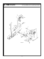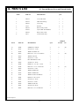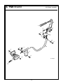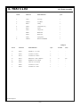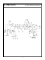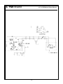
1
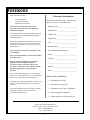
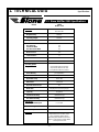
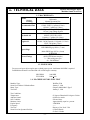
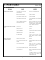
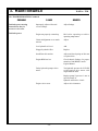
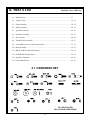
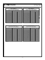
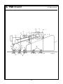
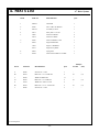
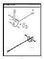
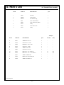
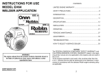
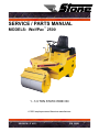
SERVICE / PARTS MANUAL MODELS: WolfPac 2500 1 - 1/4 TON STATIC RIDE ON A 100% employee-owned American manufacturer REVISION: D 4/02 P/N 56383 TABLE of CONTENTS FOREWORD WolfPac 2500 ................................................................................................................................... 5 LIMITED WARRANTY ................................................................................................................................. 6 SECTION 1 - TECHNICAL DATA ................................................................................................................ 7 - 9 1.1 Specifications ............................................................................................................................... 8 1.2 Machine Data ............................................................................................................................... 9 1.3 Engine RPM ................................................................................................................................. 9 1.4 Machine Sound Level Test ........................................................................................................... 9 SECTION 2 - HEALTH & SAFETY .............................................................................................................. 11 - 16 SECTION 3 - MAINTENANCE ..................................................................................................................... 17- 30 3.1 Introduction & Operating Principle ............................................................................................. 18 3.1.1 Important Maintenance Information .................................................................................. 19 3.2 Maintenance Chart ....................................................................................................................... 20 3.3 Maintenance Overview ................................................................................................................ 21 3.3.1 Additional Service Information .......................................................................................... 21 3.4 Engine Oil ................................................................................................................................... 21 3.4.1 Honda ................................................................................................................................. 21 3.4.2 Robin .................................................................................................................................. 21 3.5 Air Cleaner ................................................................................................................................... 21 3.6 Spark Plugs .................................................................................................................................. 21 - 22 3.7 Engine RPM ................................................................................................................................. 22 3.8 Cleaning 3.9 Valve Clearance ........................................................................................................................... 22 ................................................................................................................................... 22 3.10 Hydraulic Oil ................................................................................................................................ 22 3.11 Hydraulic Oil Filter ...................................................................................................................... 22 - 23 3.12 Hydraulic Breather Cap ............................................................................................................... 23 3.13 Grease Fittings ............................................................................................................................. 23 3.14 Chain ................................................................................................................................... 23 3.14.1 Chain Adjustment ...................................................................................................... 23 3.15 Fuel Cap/Strainer ......................................................................................................................... 23 3.16 Sediment Cup/Filter ..................................................................................................................... 23 3.17 Fuel Tank ................................................................................................................................... 23 3.18 Fuel Lines ................................................................................................................................... 23 3.19 Forward/Reverse/Neutral Adjustment .......................................................................................... 23 - 24 3.20 Neutral Interlock Adjustment ....................................................................................................... 24 3.21 Control Cables ............................................................................................................................. 24 TABLE of CONTENTS WolfPac 2500 3.22 Parking Brake ............................................................................................................................... 24 - 25 3.23 Throttle Lever .............................................................................................................................. 25 3.24 Water Tank ................................................................................................................................... 25 3.25 Sprinklers ................................................................................................................................... 25 3.26 Engine Mounting .......................................................................................................................... 25 3.27 Hardware ................................................................................................................................... 25 3.28 Loctite ................................................................................................................................... 25 - 26 3.29 Battery ................................................................................................................................... 26 - 27 3.29.1 Servicing Battery ....................................................................................................... 26 - 27 3.29.2 Battery Installation .................................................................................................... 27 3.30 Jump Starting ............................................................................................................................... 27 3.31 Charge System .............................................................................................................................. 27 3.32 Switch Box/Fuse 5A (Honda Only) ............................................................................................. 27 3.32.1 Specified Fuse: 5A .................................................................................................... 27 3.33 Ignition System ............................................................................................................................ 27 3.34 Belt Tension ................................................................................................................................. 27 3.35 Storage ................................................................................................................................... 27 3.36 Troubleshooting ........................................................................................................................... 28 - 29 3.37 Service Record ............................................................................................................................. 30 SECTION 4 - EXPLODED VIEWS WITH PARTS ..................................................................................... 31 - 63 4.1 Hardware Key .............................................................................................................................. 33 4.2 Torque Charts ............................................................................................................................... 34 - 35 4.3 Frame Assembly ........................................................................................................................... 36 - 39 4.4 Roller Assembly ........................................................................................................................... 40 - 41 4.5 Sprinkler Assembly ...................................................................................................................... 42 - 43 4.6 Hydraulic Assembly ..................................................................................................................... 44 - 47 4.7 Drive System ................................................................................................................................ 48 - 49 4.8 Throttle/Choke Assembly ............................................................................................................. 50 - 51 4.9 Forward/Reverse Lever and Neutral Switch ................................................................................ 52 - 53 4.10 Brake Assembly ........................................................................................................................... 54 - 55 4.11 8HP & 11HP Honda Wiring Harness ........................................................................................... 56 - 57 4.12 8.5HP Robin Wiring Harness ....................................................................................................... 58 - 59 4.13 Hydraulic Schematic .................................................................................................................... 60 - 61 4.14 Decal Identification ...................................................................................................................... 62 - 63 CALIFORNIA PROPOSITION 65 WARNING ........................................................................................... 67 FOREWORD Warranty Information These instructions include: Safety regulations Operating instructions Maintenance instructions Please enter the following data. This will help expedite any service or warranty work. These instructions have been prepared for operation on the construction site and for the maintenance engineer. 1. Machine Type: _______________________ These instructions are intended to simplify operation of the machine and to avoid malfunctions through improper operation. 2. Engine Type: _________________________ Observing the maintenance instructions will increase the reliability and service life of the machine when used on the construction site and reduce repair costs and downtimes. Always keep these instructions at the place of use of the machine. Machine S/N: ________________________ Engine S/N: __________________________ 3. VIN: _______________________________ 4. Purchase Date: _______________________ 5. Dealer/Distributor Information: Name: ______________________________ Only operate the machine as instructed and follow these instructions. Address: ____________________________ Observe the safety regulations as well as the guidelines of the civil engineering trade association. Observe the safety rules for the operation of road rollers and compactors and the pertinent regulations for the prevention of accidents. Stone Construction Equipment, Inc. is not liable for the function of the machine when used in an improper manner or for other than the intended purpose. ____________________________________ Phone #: ____________________________ Fax #: ______________________________ Location of above information: 1. Information on S/N tag. Operating errors, improper maintenance and the use of incorrect operating materials are not covered by the warranty. 2. Information on engine tag. 3. Information on S/N tag - if applicable. The above information does not extend the warranty and liability conditions of business of Stone Construction Equipment, Inc. 4. Date you purchased machine. 5. Dealer machine was purchased from. Stone Construction Equipment, Inc. P.O. Box 150, Honeoye, New York 14471 Phone: (800) 888-9926 Fax: (585) 229-2363 -5- L i m i t e d W a r r a n t y The Manufacturer warrants that products manufactured shall be free from defects in material and workmanship that develop under normal use for a period of 90 days for concrete vibrators and electric pumps, one year for Rhino®, Bulldog®, WolfPac Rollers, trowels, Stompers®, saws, forward plates, engine powered pumps, Lift Jockey, Mortar Buggy and 6 months for all other products from the date of shipment. The foregoing shall be the exclusive remedy of the buyer and the exclusive liability of the Manufacturer. Our warranty excludes normal replaceable wear items, i.e. gaskets, wear plates, seals, O-rings, V-belts, drive chains, clutches, etc. Any equipment, part or product which is furnished by the Manufacturer but manufactured by another, bears only the warranty given by such other manufacturer. (The Manufacturer extends the warranty period to “Lifetime” for the drum bearings and seals for the mortar mixers, and agrees to furnish, free of charge, the bearings and seals only upon receipt of the defective parts. The warranty is two years for eccentric bearings on the forward plate compactors, mortar and plaster mixer drums, trowel gearboxes and five years on the Bulldog trench roller eccentric bearings.) A Warranty Evaluation Form must accompany all defective parts. Warranty is voided by product abuse, alterations, and use of equipment in applications for which it was not intended, use of non-manufacturer parts, or failure to follow documented service instructions. The foregoing warranty is exclusive of all other warranties whether written or oral, expressed or implied. No warranty of merchantability or fitness for a particular purpose shall apply. The agents, dealer and employees of Manufacturer are not authorized to make modification to this warranty, or additional warranties binding on Manufacturer. Therefore, additional statements, whether oral or written, do not constitute warranty and should not be relied upon. The Manufacturer’s sole responsibility for any breach of the foregoing provision of this contract, with respect to any product or part not conforming to the Warranty or the description herein contained, is at its option (a) to repair, replace or refund such product or parts upon the prepaid return thereof to location designated specifically by the Manufacturer. Product returns not shipped prepaid or on an economical transportation basis will be refused (b) as an alternative to the foregoing modes of settlement - the Manufacturer’s dealer to repair defective units with reimbursement for expenses, except labor, and be reviewed with the Manufacturer prior to repair. A Warranty Evaluation Form must accompany all warranty claims. Except as set forth hereinabove and without limitation of the above, there are no warranties or other affirmations which extends beyond the description of the products and the fact hereof, or as to operational efficiency, product reliability or maintainability or compatibility with products furnished by others. In no event whether as a result of breach of contract or warranty or alleged negligence, shall the Manufacturer be liable for special or consequential damages including but not limited to: Loss of profits or revenues, loss of use of the product or any associated product, cost of capital, cost of substitute products, facilities or services or claims of customers. No claim will be allowed for products lost or damaged in transit. Such claims should be filed with the carrier within fifteen days. Effective September 2001. Bred Tough, Technology Born To Work. The Way It Ought To Be. Stone Construction Equipment, Inc. Phone: 1-800-888-9926 • 1-585-229-5141 8662 Main Street, P. O. Box 150 Fax: 1-585-229-2363 Honeoye, NY 14471-0150 www.stone-equip.com • e-mail: [email protected] -6- 9/01 P/N 51018 1. TECHNICAL DATA -7- 1. TECHNICAL DATA ® Specifications 1.1 Stone WolfPac 2500 Specifications MODEL STONE WolfPac 2500 Dimensions LxWxH 84" x 36" x 56" Weight Total Dry 1585 lbs. Operating Weight 2070 lbs. Weight Ballasted Out 2680 lbs. Front Roller Dia. Rear Roller Dia. Front Roller Width Rear Drive Roller Width 20" 24" 28" 32" Wall Clearance 1/2" Curb Clearance 9" Wheelbase 58" Drum Thickness 3/8" Operating System Engine 8.5 hp Robin with low oil alert 8 hp Honda with low oil alert 11 hp Honda with low oil alert Power Steering yes (hydraulic) Hydrostatic Transmission yes Hydrostatic Pump Eaton #11 Drive Motor Char-Lynn Hydraulic Reservoir Cap. Water Tank 6.7 Polyethylene (w/ level gauge) Capacity 30 gallons Front Roller Mounting (4) Ball Bearings Rear Roller Mounting (2) Ball Bearings Performance Infinitely Variable Speed 0 - 4.5 mph Inside Turning Radius 8.3 ft Gradeability Standards 30% (17°) Cocoa Mat, Machined Drums, Adjustable Seat, Tool Box Under Seat, Feathering System (Trans), Neutral Ignition Interlock, Enclosed Engine Compartment, Parking Brake - hand operated, disc -8- Machine Data/Engine RPM/ Machine Sound Level Test 1. TECHNICAL DATA 1.2 MACHINE DATA Brakes Service Parking Recommended Fuel Electric Hydraulic Oil Engine Oil Hydrostatic Manual Operation Disc Gasoline 86 Octane Minimum Gx240 / EH25 1.6 gallons (6 liters) Gx340 1.7 gallons (6.5 liters) 12-Volt System Battery BCI Group U1 - 12 165 cca 5 amp Charge System Mobilfluid 424 (VI-152) SUS255 55CST ISO VG55 Capacity 6.7 gallons (25.4 liters) Mobil Delvac 1200 10W-30 (API, SH or SJ) Gx240 / Gx340 Capacity 1.16 quarts (1.1 liters) EH25 1.06 quarts (1 liter) Honda Gx240 / Gx340 NGK BRP6ES gap .028 in. (.7 mm) Spark Plugs Grease Fittings Robin EH250 gap .025 in. (.6 mm) NGKBGHS Mobilgrease XHP 222 (NLGI 2EP lithium complex) 2 - 3 Hits with grease gun 90 - 120 Milliliters 1.3 ENGINE RPM Do not exceed rpm, adjust engine rpm to obtain proper speed. A minimum idle RPM is required. Full RPM should not be exceeded and will void the engine warranty. IDLE RPM FULL RPM 1400 MIN 3600 +100 1.4 MACHINE SOUND LEVEL TEST Machine Type: Sound Level Meter Calibration Date: Meter Type: Test Date: WolfPac 2500 January 2, 1996 Simpson Model 886-2 Type 2 January 2, 1996 Test Conditions: Temperature: Ambient Sound: Soil Condition: Moisture Limit: Engine Speed: Frequency: Test Site: Sound Level at Operator Position: 65 degrees Fahrenheit/18 degrees Celsius 60 dba slow mode Silts and clays Approximately equal to - percent 3600 RPM ----Honeoye, New York USA 95 dba 8 Honda 93 dba 11 Honda -9- 2. HEALTH & SAFETY - 11 - 2. HEALTH & SAFETY Before using this equipment, study this entire manual to become familiar with its operation. Do not allow untrained or unauthorized personnel, especially children, to operate this equipment. Use only factory authorized parts for service. Safety Precautions When warning decals are destroyed or missing, contact the Manufacturer immediately at 1-800-888-9926 for replacement. For the safety of yourself and others, it is imperative that the following rules are observed. Failure to do so may result in serious injury or death. FOLLOW SAFETY INSTRUCTIONS Carefully read all safety messages and decals in this manual and on your machine safety signs. Keep decals in good condition. Replace missing or damaged decals. Be sure new equipment components and repair parts include the current safety signs. Replacement safety signs and decals are available through your dealer. Learn how to operate the machine and how to use controls properly. Do not let anyone operate without instruction. Keep your machine in proper working condition. Unauthorized modifications to the machine may impair the function and/or safety and affect machine life. If you do not understand any part of this manual and need assistance, contact your dealer. This notation appears before warnings in the text. It means that the step which follows must be carried out to avoid the possibility of personal injury or death. These warnings are intended to help the technician avoid any potential hazards encountered in the normal service procedures. We strongly recommend that the reader takes advantage of the information provided to prevent personal injury or injury to others. UNDERSTAND SIGNAL WORDS A signal word DANGER, WARNING, or CAUTION is used with the safety-alert symbol. DANGER identifies the most serious hazards. DANGER or WARNING safety signs are located near specific hazards. General precautions are listed on CAUTION safety signs. CAUTION also calls attention to safety messages in this manual. - 12 - 2. HEALTH & SAFETY Safety Precautions USE COMMON SENSE WHEN HANDLING FUELS Transport and handle fuel only when contained in approved safety container. Do not smoke when refueling or during any other fuel handling operation. Do not refuel while the engine is running or while it is still hot. If fuel is spilled during refueling, wipe it off from the engine immediately and discard the rag in a safe place. Do not operate the equipment if fuel or oil leaks exist - repair immediately. Never operate this equipment in an explosive atmosphere. Operator must always be seated when roller is running. Never allow more than one person on roller. Always turn engine off before dismounting from roller. Always apply parking brake when not in use. Never park roller on a hill. Never operate roller on slope greater than 15 degrees. Do not operate the roller in standing water. Ear protection required when operating this equipment. Exposure to loud noise can cause impairment or loss of hearing. HOT SURFACES Muffler, engine, and engine shroud may be hot. Allow all components in the engine compartment to cool before performing any service work. Never operate unit in a poorly ventilated or enclosed area. Avoid prolonged breathing of exhaust gases. Engine exhaust fumes can cause sickness or death. - 13 - 2. HEALTH & SAFETY Safety Precautions Qualified personnel only. No untrained operators. Serious injury may occur. Users must be trained to operate this roller. Read the Operator's Manual and Engine Owner's Manual. Learn to operate this roller safely. Do not articulate on grades larger than 15o, roller may tip over. Do not operate across the sides of hills, roller may tip over. Do not operate at the edge of mats or roads, roller may tip over. Do not stand, be seated when roller is running. Do not park the roller on hills. Always turn off engine and apply brake before dismounting. Hydraulic system produces high pressures--incorrect hose replacement can cause serious personal injury. When performing service, refer to Operator's Manual for hose identification and connections. Caution: Escaping hydraulic fluid under pressure can have sufficient force to penetrate the skin, causing serious personal injury. Hydraulic fluid escaping under pressure from a very small hole can be almost invisible. Use a piece of cardboard or wood to search for possible leaks. Never use your hands to detect pressure leaks. Hydraulic tank temperature can reach 180o F maximum. Pressurized release of fluids from hydraulic system can cause serious burns. Shut off engine. Only remove filler cap when cool enough to touch with bare hands. Slowly loosen cap to first stop to relieve pressure before removing completely. Never perform any work on the roller while it is running. Before working on the roller, stop the engine and disconnect the spark plug wire(s) to prevent accidental starting, block drums to prevent rolling. Keep engine cover closed during the operation. Keep hands, clothing and jewelry away from all moving parts. Keep all guards in place. - 14 - 2. HEALTH & SAFETY Safety Precautions Keep feet clear of all drums. Keep work area free of bystanders. For foot protection, wear steel toe shoes or toe pads. Caution: Keep away from the machines articulation area when the engine is running. Only start engine from operators seat. Before starting machine, make sure that there are no persons or obstacles near or under machine. PRACTICE SAFE MAINTENANCE Understand service procedure before doing work. Keep area clean and dry. Never lubricate, service or adjust machine while it is moving. Keep hands, feet, and clothing from power-driven parts. Disengage all power and operate controls to relieve pressure. Lower equipment to the ground. Stop the engine. Remove the key. Allow machine to cool. Securely support any machine elements that must be raised for service work. Keep all parts in good condition and properly installed. Fix damage immediately. Replace worn or broken parts. Remove any buildup of grease, oil, or debris. Disconnect battery ground cable (-) before making adjustments on electrical systems or welding on machine. PREPARE FOR EMERGENCIES Be prepared if a fire starts. Keep a first aid kit and fire extinguisher handy. Keep emergency numbers for doctors, ambulance service, hospital, and fire department near your telephone. - 15 - 2. HEALTH & SAFETY Safety Precautions Starting fluid (ether) is highly flammable, do not use or an explosion or fire may result. WEAR PROTECTIVE CLOTHING Wear close fitting clothing and safety equipment appropriate to the job. Prolonged exposure to loud noise can cause impairment or loss of hearing. Wear a suitable hearing protective device such as earmuffs or earplugs to protect against objectionable or uncomfortable loud noises. Operating equipment safely requires the full attention of the operator. Do not wear radio or music headphones while operating machine. PREVENT BYPASS STARTING Avoid possible injury or death from engine runaway. Do not start engine by shorting across starter terminal. Engine will start with PTO engaged if normal circuitry is bypassed. Start engine only from operators station with PTO disengaged or in neutral. DISPOSE OF WASTE PROPERLY Improperly disposing of waste can threaten the environment and ecology. Potentially harmful waste used with equipment include such items as oil, fuel, coolant, brake fluid, filters, and batteries. Use leakproof containers when draining fluids. Do not use food or beverage containers that may mislead someone into drinking from them. Do not pour waste onto the ground, down a drain, or into any water source. Air conditioning refrigerants escaping into the air can damage the Earths atmosphere. Government regulations may require a certified air conditioning service center to recover and recycle used air conditioning refrigerants. Inquire on the proper way to recycle or dispose of waste from your local environmental or recycling center. - 16 - 3. MAINTENANCE - 17 - 3. MAINTENANCE WolfPac 2500 3.1 INTRODUCTION & OPERATING PRINCIPLE Congratulations on your purchase of the WolfPac 2500! You've made an excellent choice! The WolfPac 2500 is ergonomically engineered to optimize operator interface with the total machine--it's really "user friendly". Besides good visibility to the roll-edge as well as the work surface, you'll find that the controls are exactly in the right places for maximum comfort. The roller is designed to give you high productivity at a low cost. High compaction force is obtained by the line contact the drum makes with the surface to be compacted. A two inch wide contact area over the length of the drum, produces more than ten times the unit area pressure than that of a ten thousand pound eccentric force vibratory plate compactor. This product is completely hydrostatically controlled. The variable flow pump delivers oil to the fixed displacement motor which in turn drives the rear drum via a chain. Movement of the forward / reverse lever allows infinitely variable speed in both the forward and reverse direction. The feathering characteristics of the pump eliminates scuffing and or tearing of the asphalt mat when changing direction. There is power steering--a feature no operator wants to be without. This eliminates the hard steering and erratic movement that an operator experiences with no power steering units. A 30-gallon polyethylene water tank provides long running time between refills. A water level sight gauge, visible from the operator's compartment, can be monitored during actual operation. The low maintenance, gravity flow sprinkler system features dual controls and noncorrosive sprinkler bars. For spreading the water and cleaning the drums, there are cocoa mats and scrapers. Upon receipt of your WP2500, carefully check for any freight damage. Any damage should be immediately reported to the carrier and a claim registered. The roller is manufactured to the strictest specifications and inspection procedures. If any material or manufacturing defects are found, return the tag on the machine with assembler's signature and your findings to the manufacturer. We want to know when a product is less than perfect. We also welcome any and all input on how the product may serve you better. The following instructions were compiled to provide you information on how to obtain long and trouble free use of the roller. Periodic maintenance of the roller is essential. Read the manual in its entirety and follow the instructions carefully. Failure to do so may injure yourself or a bystander. - 18 - 3. MAINTENANCE WolfPac 2500 3.1.1 Important Maintenance Information F IMPORTANT The person attempting any of the following maintenance tasks must be authorized to do so and have read and understood all sections within this manual. - 19 - 3. MAINTENANCE WolfPac 2500 3.2 MAINTENANCE CHART - 20 - 3. MAINTENANCE WolfPac 2500 3.3 MAINTENANCE OVERVIEW 4. Run engine for 2 3 minutes, stop engine and check oil level and check for leaks. WARNING NOTE: Please dispose of used motor oil and filter in a manner that doesnt harm the environment. BEFORE MAKING ANY ADJUSTMENTS, BE SURE THE ROLLER IS PARKED ON LEVEL GROUND, PARKING BRAKE IS ON AND DRUMS ARE BLOCKED. DISCONNECT BATTERY TO AVOID ACCIDENTAL IGNITION OF ENGINE OR SEVERE PERSONAL INJURY MAY OCCUR. Under heavy loads, change engine oil more frequently. 3.5 AIR CLEANER IMPORTANT: Read Engine Manual before operating or performing maintenance. 3.3.1 Additional Service Information Foam Pre-cleaner: Clean in warm soapywater, rinse and dry thoroughly. Apply oil to the foam and squeeze out excess oil. The engine will smoke if too much oil is left in the foam. Paper Element: Tap the element lightly on a hard surface to remove excess dirt or blow pressurized air (30 psi max.) through the filter from the air cleaner cover side. Do not brush the dirt off. This is not a detailed engine service manual. If you want more detailed service information refer to engine manuals: 56343 Honda Manual Engine GX240/GX340 56344 Robin Manual Engine EH250 Replace elements if damaged or excessively dirty. 3.4 ENGINE OIL 3.6 SPARK PLUGS 3.4.1 Honda To ensure proper engine operation, the spark plug must be properly gapped and free of deposits. Replace oil at 20 hours, then change oil every 100 hours. 3.4.2 Robin Replace oil at 20 hours, then change oil every 50 hours. 1. Remove the oil filler cap drain bolt. Drain oil into a suitable container. Clean and replace at scheduled maintenance. Clean engine before removing spark plugs. Visually inspect the spark plug, discard if insulator or tip is damaged. Check that the spark plug washer is in good condition. If spark plug is to be reused, clean with a wire brush and set plug gap. Thread the spark plug in by hand to prevent cross threading. After the spark plug is seated, tighten with a spark plug wrench to compress the washer. 2. Clean and install the drain bolt, tighten securely. 3. Fill with the recommended oil, fill to the upper limit mark on the dipstick, and tighten the oil filler cap securely. If installing a new spark plug, tighten 1/2 turn after the spark plug seats to compress the washer. If reinstalling a used spark plug, tighten 1/8 1/4 turn after the spark plug seats to compress the washer. NOTICE: The spark plug must be securely tightened. - 21 - 3. MAINTENANCE WolfPac 2500 An improperly tightened spark plug can become very hot and may cause engine damage. Use only the recommended spark plug or equivalent. A spark plug that has an improper heat range may cause engine damage. IF YOU ARE INJURED BY ESCAPING HYDRAULIC FLUIDS, SEE A DOCTOR AT ONCE. SERIOUS INFECTION OR REACTION CAN DEVELOP IF PROPER MEDICAL TREATMENT IS NOT ADMINISTERED IMMEDIATELY. Mobilfluid 424 is recommended for the hydraulic system. Do not mix hydraulic oils. Check oil level daily, replace hydraulic oil every 800 hours. 3.7 ENGINE RPM Start the engine and allow it to warm up to normal operating temperature, check the idle speed (1,400 + 100), and adjust idle stop screw as required. 1. Clean hydraulic tank, remove oil breather cap slowly. Check the full speed, Honda 3,600 + 100. Adjust full speed stop screw as required. 2. Remove drain plug and drain into suitable container. 3.8 CLEANING 3. Clean drain plug, apply thread sealant to the plug, install and tighten. The machine should be cleaned at scheduled maintenance. This should include cleaning the engine cooling fins. Wash machine with warm soapy water, rinse off mud and dirt with water and use pressurized air (30-psi max.) to blow dirt and debris from fins and engine. 4. Add fresh hydraulic oil until level is 1 1/2" - 2" from the top of the expansion tank. 5. Clean breather cap, install and tighten. 3.9 VALVE CLEARANCE 6. Idle engine 2-3 minutes, stop engine and check oil level. Due to special tool requirements and training, an authorized engine dealer should perform this service unless the owner has the proper tools and proper shop manuals. 3.10 HYDRAULIC OIL WARNING ESCAPING HYDRAULIC FLUID UNDER PRESSURE CAN HAVE SUFFICIENT FORCE TO PENETRATE THE SKIN, CAUSING SERIOUS PERSONAL INJURY. HYDRAULIC FLUID ESCAPING UNDER PRESSURE FROM A VERY SMALL HOLE CAN BE ALMOST INVISIBLE. USE A PIECE OF CARDBOARD OR WOOD TO SEARCH FOR POSSIBLE LEAKS. NEVER USE YOUR HANDS TO DETECT PRESSURE LEAKS. CAUTION: If hoses, filter and/or hydraulic components were changed, start the engine and purge the air from the system prior to checking the oil level. To do this, idle the engine for three minutes with control lever in NEUTRAL position. Slowly engage forward to reverse. This allows fluid to replace air introduced with the filter change. If this procedure is not followed, partial or complete failure of the pump may result. 3.11 HYDRAULIC OIL FILTER Replace at 5 hours. This is to rid the system of any trapped contamination from the wear-in of parts. Then replace every 100 hours. Use beta rated filter (i.e. Parker 12AT-10C,10 micron filter). - 22 - 3. MAINTENANCE WolfPac 2500 3.15 FUEL CAP/STRAINER 1. Remove the spin-on hydraulic oil filter. 2. Lightly oil the seal on the new filter, install and tighten. Check daily. Clean every six months or 100 hours. 3. Idle engine 2-3 minutes stop engine and check for proper hydraulic oil level and check for leaks. Clean every 100 hours. 3.16 SEDIMENT CUP/FILTER 3.17 FUEL TANK CAUTION: NEVER overfill the hydraulic tank. Before disconnecting any hydraulic lines, be sure engine is shut off and relieve all pressure. Before applying pressure to system, be sure all connections are tight and lines, fittings and hoses are not damaged. Drain and flush the fuel tank every 300 hours or yearly. 3.18 FUEL LINES Inspect fuel line condition and clamps weekly. Replace fuel lines every 2 years. 3.12 HYDRAULIC BREATHER CAP 3.19 FORWARD/REVERSE/NEUTRAL ADJUSTMENT Replace every 800 hours or yearly. The forward/reverse lever should be aligned with NEUTRAL on the console when the roller is moving neither forward nor reverse with the engine running. If the lever is not aligned, adjust it as described below. 3.13 GREASE FITTINGS Use a grease gun to grease below fittings, use lithium grease. Remove the blue protection cap off fitting before greasing. Steering Pivot Pin Steering Tilt Block Steering Pivot Arm Rear Drum Bearings (2) 1. Check neutral switch mounting and adjust screw nuts. They are loctited at factory and must be secure. Check and if required, adjust neutral safety switch. See Neutral Interlock Adjustment. 3.14 CHAIN Lubricate weekly with chain lube, inspect connecting links and check chain slack 3/8-1/2 inch. Chain lubrication is required weekly. To avoid sprocket wear, replace chain when fully stretched. For chain replacement, use only factory authorized parts. 2. Shut off the engine with the forward/reverse lever lift in operating neutral position. The position when the roller moves neither forward nor reverse. Apply the parking brake. 3.14.1 Chain Adjustment 4. Disconnect the linkage from the hydrostatic transmission. Do this by removing the lock nut and bolt from the rod end. Loosen mounting bolts on side, tighten chain 3/8 to 1/2 inch chain slack. For further chain adjustment, remove the half link. Retighten mounting bolts. Avoid overtightening chain as this causes excessive wear and power loss. - 23 - 3. Remove the engine access panel. 5. Move transmission lever to forward position and check for proper alignment. Now move lever to reverse position and check for proper 3. MAINTENANCE WolfPac 2500 3.21 CONTROL CABLES alignment. To accommodate both lever positions, adjust rod end accordingly. Transmission lever may deflect slightly in either position. Forward/reverse, brake, throttle, and choke. Lubricate all cable ends every 200 hours with penetrating oil. 6. Secure the rod end to the transmission lever with the nut and bolt, secure with lock nut. WARNING DO NOT ADJUST THE CONTROL CABLE WITH THE POWER ON OR THE ENGINE RUNNING. SERIOUS INJURY OR DEATH COULD RESULT. Linkage play must be minimal at both connections. Replace rod ends and/or link if required. 3.20 NEUTRAL INTERLOCK ADJUSTMENT The purpose of the neutral interlock switch is to prevent engine from starting when the forward/reverse lever is NOT in the NEUTRAL position. 1. Disconnect the battery cables from the battery. 2. a. Disconnect two wires from neutral interlock switch and connect it to leads from an ohmmeter. b. When switch is actuated, ohmmeter should read zero resistance. 3. Adjust switch back in and out to obtain the proper engagement time. Proper engagement time, reading on the ohmmeter, is a maximum movement of the forward reverse lever at the surface of the console of 1/4 inch. The center of the engagement time should be within 1/16 of the NEUTRAL position. A GRADUAL OR SUDDEN INCREASE IN THE NO-LOAD FRICTION (CABLE DISCONNECT AT BOTH ENDS) OF A CONTROL CABLE IS AN INDICATION OF A PENDING OR PRESENT PERFORMANCE PROBLEM. THE CONTROL CABLE SHOULD BE REPLACED, OTHERWISE SERIOUS INJURY OR DEATH COULD RESULT. A GRADUAL OR SUDDEN DECREASE IN THE USABLE STROKE IS AN INDICATION OF A PENDING OR PRESENT PERFORMANCE PROBLEM. THE CONTROL CABLE SHOULD BE REPLACED, OTHERWISE SERIOUS INJURY OR DEATH COULD RESULT. CONTROL CABLES THAT HAVE MOISTURE INSIDE OF THEM AND/OR HAVE FROZEN SHOULD BE REPLACED. DO NOT APPLY HEAT TO THAW OR DRY CONTROL CABLES. 3.22 PARKING BRAKE 4. Once neutral switch location is fixed, back stop screws out and move transmission lever to forward position. Turn top screw in until lever backs off forward position. Turn screw one additional turn and tighten lock nut. Move lever to reverse position and repeat above using lower screw. Periodically the brakes should be inspected and tested. If adjustments are needed, follow these brake adjustment procedures. 5. Disconnect ohmmeter and reconnect interlock wires and battery cables. - 24 - 1. Block the drums to prevent rolling. 2. Disengage brake. 3. MAINTENANCE WolfPac 2500 3.23 THROTTLE LEVER 3. Pull the cotter pin from the clevis pin, remove clevis pin from clevis and loosen the locking nut below the clevis. Throttle should operate smoothly and hold engine at full RPM. Throttle should require 10 lbs. to operate. To adjust tension, loctite locknut and tighten until 10 lbs. is required to move from full to idle position. 3.24 WATER TANK The water tank is polyethylene to prevent corrosion. The water tank holds 65 US gallons. Dirty water will clog the sprinkler bars. If the water tank is subject to freezing temperatures, all the water lines and the water tank must be drained by drawing through sprinkler tubes or removing the cover at the rear of the machine to gain access to the water tank, flush and drain plug. Figure 1 4. If contact pressure needs to be added to the brakes, the clevis should be turned clockwise. To relieve pressure, turn the clevis counterclockwise. 3.25 SPRINKLERS 5. The clevis should not be turned in either direction more than one full revolution before being tested. Replace clevis pin and cotter pin and test. Use a spring scale to measure the force needed to engage the brake. Attach the scale to brake lever and pull to engage the brake. See reference figure 2. The scale should read between 40 to 45 lbs. Repeat steps 3 and 4 until correct force is obtained. The sprinkler tube assemblies are PVC to prevent corrosion. The sprinkler tube assemblies are removable for cleaning when required. 3.26 ENGINE MOUNTING Check weekly. Tighten all mounting hardware for proper torque, refer to parts illustrations for proper torque. 3.27 HARDWARE Inspect all hardware for tightness. Refer to parts illustrations for proper torque. Shear bolts are designed to fail under predetermined loads. Always replace shear bolts with identical grade. Fasteners should be replaced with the same or higher grade. If higher grade fasteners are used, these should only be tightened to the strength of the original. Make sure fasteners threads are clean and that you properly start thread engagement. This will prevent them from failing when tightening. 3.28 LOCTITE Figure 2 Loctite 262 threadlocker is required to prevent hardware from loosening. - 25 - 3. MAINTENANCE WolfPac 2500 Refer to exploded diagrams and parts list for * where loctite is required. 3.29 BATTERY battery, posts and terminals. Disconnect battery cables before charging to avoid damage to the electrical system. WARNING 3.29.1 Servicing Battery WARNING BATTERY GAS CAN EXPLODE. KEEP SPARKS AND FLAMES AWAY FROM BATTERIES. USE A FLASHLIGHT TO CHECK BATTERY ELECTROLYTE LEVEL. SULFURIC ACID IN BATTERY ELECTROLYTE IS POISONOUS. IT IS STRONG ENOUGH TO BURN SKIN, EAT HOLES IN CLOTHING AND CAUSE BLINDNESS IF SPLASHED INTO EYES. Avoid the hazard by: Filling batteries in a well-ventilated area. NEVER CHECK BATTERY CHARGE BY PLACING A METAL OBJECT ACROSS THE POSTS. USE A VOLTMETER OR HYDROMETER. Wearing eye protection and rubber gloves. Avoiding breathing fumes when electrolyte is added. ALWAYS REMOVE GROUNDED NEGATIVE (-) BATTERY CLAMP FIRST AND REPLACE IT LAST. Avoiding spilling or dripping electrolyte. Using proper jump start procedure. 1. On regular batteries, check electrolyte level. Fill each cell to bottom of filler neck with distilled water. If you spill acid on yourself: 1. Flush your skin with water. 2. Keep batteries clean by wiping them with a damp cloth. Keep all connections clean and tight. Remove any corrosion, and wash terminals with a solution of 1 part baking soda and 4 parts water. Tighten all connections securely. NOTE: Coat battery terminals and connectors with a mixture of petroleum jelly and baking soda to retard corrosion. 3. Flush your eyes with water for 10 15 minutes. Get medical attention immediately. If acid is swallowed: 1. Drink large amounts of water or milk. 3. Keep battery fully charged, especially during cold weather. If a battery charger is used, turn charger off before connecting charger to battery(ies). Attach POSITIVE (+) battery post. Then attach NEGATIVE (-) battery charger lead to a good ground. Once a month, check the battery for proper charge of 12.5 volts. Check for proper fluid level. Use distilled water when adding and run 30 minutes to mix. Clean 2. Apply baking soda or lime to help neutralize the acid. 2. Then drink milk of magnesia, beaten eggs, or vegetable oil. 3. Get medical attention immediately. In freezing weather, run engine at least 30 minutes to assure thorough mixing after adding water to battery. If necessary to replace battery(ies), replacements must meet or exceed the following recommended - 26 - 3. MAINTENANCE WolfPac 2500 capabilities at - 18° C (0° F): NOTICE: Electrical system is not designed for field add-on electrical options, DO NOT modify the electrical system. Contact your authorized dealer. 12 Volt Standard duty battery BCI group U1 - 12 165CCA 3.32.1 Specified Fuse: 5A 3.29.2 Battery Installation WARNING ALWAYS CONNECT GROUNDED CABLE LAST. CLEAN AND SECURELY CONNECT EACH CABLE TO BATTERY TERMINAL OF THE SAME POLARITY. BATTERY SHOULD BE SECURELY FASTENED WITH PROPERLY INSTALLED HOLD-DOWNS. 3.30 JUMP STARTING Turn the engine switch OFF and remove the key before checking or replacing fuses to prevent accidental shortcircuiting. To replace fuse, pull the old fuse out of the clips with your finger. Push a new fuse into the clips. NOTICE: NEVER use a fuse with a different rating from that specified. Serious damage to the electrical system or a fire may result. 3.33 IGNITION SYSTEM CAUTION: DO NOT let vehicles touch. Put emergency brake ON. Set both vehicles in PARK (NEUTRAL if manual transmission) and turn ignition and electrical accessories OFF. The WP2500 is equipped with electronic ignition. Checking and replacing the spark plug is the only ignition system maintenance required. Attach jumper cables in this order: 3.34 BELT TENSION 1. dead positive block to Check belts and idler weekly for proper tension. For optimum performance, replace belt yearly. If any belt squealing is present, belts must be tightened or replaced. 2. good positive 3. good negative to 3.35 STORAGE 4. engine block or frame of dead car. Start GOOD vehicle and let run a few minutes. Then start DEAD VEHICLE. Remove cables in reverse order 4, 3, 2, 1. 1. Store the roller on level ground with drums blocked and parking brake on. 2. Remove the key. Operations of roller by untrained persons could result in personal injury. 3.31 CHARGE SYSTEM Charge system should be checked every month. With the engine running at full speed voltage should be 13 14 volts. 3. In freezing climates, drain the water from the water tank, sprinkler tubes and drums. 3.32 SWITCH BOX / FUSE 5A (HONDA ONLY) If charge system fails, check the fuse located at the key switch box. If fuse fails frequently, it usually indicates a short circuit or an overload in the electrical system. Refer to wiring diagram and inspect wires. - 27 - 4. During extended storage, drums should be coated with any type of oil or grease to prevent rusting. 5. Storage instructions for the engine are stated in the Engine Manual and should be carried out. 3. MAINTENANCE WolfPac 2500 3.36 TROUBLESHOOTING PROBLEM Engine will not crank over. Engine will not start, but cranks over. Roller will not move forward or reverse. CAUSE REMEDY Forward/Reverse lever not in neutral position. Place lever in neutral position. Battery not fully charged. Charge or replace. Loose battery or starter cables. Check and tighten. Faulty engine starting circuit. Check appropriate section in Engine Manual. Faulty or improperly adjusted neutral interlock switch. Make sure neutral switch is adjusted properly and wires are all secured. Test with ohmmeter. Readjust neutral switch. Replace if defective. Low on fuel. Add fuel. Engine low on oil. Add oil. Fuel filter plugged. Check fuel filter, replace if necessary. Spark plug fouled. Clean or replace. No spark at plug. Check low oil alert circuit - Check engine ignition system in Engine Manual. Objects in front of drums. Remove. Loose or broken forward/reverse linkage. Readjust linkage or replace worn arm linkage. Loose or broken chain. Make sure chain is on sprocket. Adjust tension or replace if chain shows excessive wear. Loose or broken transmission belts. Replace and/or tighten. Low hydraulic oil. Make sure expansion tank is max. of 1/2 full. Test hydraulic pressure for 2250 PSI at full load on drive motor with engine RPM at 3600. - 28 - 3. MAINTENANCE WolfPac 2500 3.36 TROUBLESHOOTING Continued PROBLEM Unit lacks power moving forward--but okay in reverse or vice versa. Unit lacks power. CAUSE REMEDY Improperly adjusted forward / reverse linkage. Adjust linkage. Engine not properly warmed up. Idle before operating to achieve operating temperature. Chain misalignment or too much tension. Adjust. Low hydraulic oil level. Add. Plugged hydraulic filter. Replace. Insufficient belt tension. Adjust and check spring on idle arm or replace belts. Engine RPM too low. Check throttle linkage for proper actuation (3600 RPM) Consult Engine Manual. Faulty hydraulic pump or drive motor. Test hydraulic pressure for 2250 PSI at full load on drive motor with engine RPM at 3600. Replace pump if pressure is not in specified range in hydraulic motor drive circuit. Engine valves worn. - 29 - Adjust valve clearances. 3. MAINTENANCE WolfPac 2500 3.37 SERVICE RECORD - 30 - 4. EXPLODED VIEWS WITH PARTS - 31 - 4. PARTS LIST Exploded Views with Parts 4.1 Hardware Key ................................................................................................................ 33 4.2 Torque Charts ................................................................................................................. 34 - 35 4.3 Frame Assembly ............................................................................................................. 36 - 39 4.4 Roller Assembly ............................................................................................................. 40 - 41 4.5 Sprinkler Assembly ........................................................................................................ 42 - 43 4.6 Hydraulic Assembly ....................................................................................................... 44 - 47 4.7 Drive System .................................................................................................................. 48 - 49 4.8 Throttle/Choke Assembly .............................................................................................. 50 - 51 4.9 Forward/Reverse Lever and Neutral Switch .................................................................. 52 - 53 4.10 Brake Assembly ............................................................................................................. 54 - 55 4.11 8HP & 11HP Honda Wiring Harness ............................................................................. 56 - 57 4.12 8.5HP Robin Wiring Harness ......................................................................................... 58 - 59 4.13 Hydraulic Schematic ...................................................................................................... 60 - 61 4.14 Decal Identification ........................................................................................................ 62 - 63 4.1 HARDWARE KEY ZN = ZINC PLATED BLK = BLACK OXIDE FINISH - 33 - 4. PARTS LIST 4.2 Torque Charts SAE GRADE 5 Coarse Thread, Zinc-Plated SIZE 1/4 - 20 (.250) 5/16 - 18 (.3125) 3/8 - 16 (.375) 7/16 - 14 (.4375) 1/2 - 13 (.500) 9/16 - 12 (.5625) 5/8 - 11 (.625) 3/4 - 10 (.750) 7/8 - 9 (.875) 1 - 8 (1.000) SAE GRADE 8 Coarse Thread, Zinc-Plated TORQUE ft. lbs. Nm 6 8 13 18 23 31 37 50 57 77 82 111 112 152 200 271 322 436.5 483 655 SIZE 1/4 - 20 (.250) 5/16 - 18 (.3125) 3/8 - 16 (.375) 7/16 - 14 (.4375) 1/2 - 13 (.500) 9/16 - 12 (.5625) 5/8 - 11 (.625) 3/4 - 10 (.750) 7/8 - 9 (.875) 1 - 8 (1.000) SAE GRADE 5 Fine Thread, Zinc-Plated SIZE 1/4 - 28 (.250) 5/16 - 24 (.3125) 3/8 - 24 (.375) 7/16 - 20 (.4375) 1/2 - 20 (.500) 9/16 - 18 (.5625) 5/8 - 18 (.625) 3/4 - 16 (.750) 7/8 - 14 (.875) 1 - 12 (1.000) 1 -14 (1.000) TORQUE ft. lbs. Nm 9 12 18 24 33 45 52 70 80 108 115 156 159 215 282 382 454 615 682 925 SAE GRADE 8 Fine Thread, Zinc-Plated TORQUE ft. lbs. Nm 7 10 14 19 26 35 41 56 64 87 91 123 128 173 223 302 355 481 529 717 541 733 SIZE 1/4 - 28 (.250) 5/16 - 24 (.3125) 3/8 - 24 (.375) 7/16 - 20 (.4375) 1/2 - 20 (.500) 9/16 - 18 (.5625) 5/8 - 18 (.625) 3/4 - 16 (.750) 7/8 - 9 (.875) 1 - 12 (1.000) 1 -14 (1.000) t-chrt_i.doc - 34 - TORQUE ft. lbs. Nm 10 14 20 27 37 50 58 79 90 122 129 175 180 244 315 427 501 679 746 1011 764 1036 4. PARTS LIST 4.2 Torque Charts Property Class 8.8 ZINC-PLATED SIZE M6 M8 M10 M12 M14 M16 M20 M24 Coarse Thread Nm ft. lbs. 9.9 7 24 18 48 35 83 61 132 97 200 148 390 288 675 498 Fine Thread Nm ft. lbs. 10 7 25 18 49 36 88 65 140 103 210 155 425 313 720 531 Property Class 10.9 ZINC-PLATED SIZE M6 M8 M10 M12 M14 M16 M20 M24 Coarse Thread Nm ft. lbs. 14 10 34 25 67 49 117 86 185 136 285 210 550 406 950 701 Fine Thread Nm ft. lbs. 14 10 35 26 68 50 125 92 192 142 295 218 600 443 1000 738 Property Class 12.9 ZINC-PLATED SIZE M6 M8 M10 M12 M14 M16 M20 M24 Coarse Thread Nm ft. lbs. 16.5 12 40 30 81 60 140 103 220 162 340 251 660 487 1140 841 Fine Thread Nm ft. lbs. 16.5 12 42 31 82 60 150 111 235 173 350 258 720 531 1200 885 Conversion Factor: 1 ft. lb. = 1.3558 Nm - 35 - 4. PARTS LIST 4.3 Frame Assembly 1 2 3 4 5 7 C 6 T K IE J 8 26 S 25 K F J EI Q 14,31 14,31 15 16 17 G 23 20 J D 21 22 7 sr-frasy.tif - 36 - C T 9 10 11 24 D 12 13 27 C M N S D J 30 R 32 T 28 29 A J 19 18 H 4. PARTS LIST 4.3 Frame Assembly ITEM PART NO. DESCRIPTION QTY. 1 47401 Cap Wheel Steering 1 2 46656 Nut Wheel Steering 1 3 41018 Wheel Steering 1 4 46655 Column Steering 1 5 47195 Seat Assy. 1 6 22493-2 Cover Box Tool Weld 1 7 44103 Pin Hinge BRS 1/4 x 13 - 1/2 2 8 29063-2 Board Floor 1 9 28544 THD 1/4 - 20 x 9 2 10 28543-2 Clamp Battery 1 11 35321 Battery 1 12 28446-2 Collar Pivot 1 13 32203 Bushing 2 14 46042 Fitting 1641 B 3 15 28512 Washer Thrust 1 16 32205 Bushing 2 17 27413 Washer 1 - 3/4 x 11/16 x 1/4 2 18 22485-2 Yoke Drum FRT 1 19 22761-2 Pivot York FRT 1 20 42342 Pin 1 21 22636-2 Frame Main 1 22 22267-2 Cover Engine 1 23 39999 Bumper .117 High x .50 Diameter 4 24 47244 RBR 60 Duro 1.5 x 6.75 4 25 29074-2 Cover FRT Box CONT 1 26 29065-2 Cover Control Box 1 27 36267 Switch Ignition Honda 1 28 47283 Water Tank 30 Gal. Polyethylene 1 29 47288 Cap Water Tank w/ Gauge 1 30 35483 Cap Breather & Filler 1 31 47001 Cap Blue 3 32 43117 Plate Steering 1 - 37 - 4. PARTS LIST 4.3 Frame Assembly Contd. 1 2 3 4 5 7 C 6 T K I EJ 8 26 27 C S M N S 25 K J Q D C T J 30 R 32 T 28 29 A J F 14,31 EI 14,31 15 16 17 G 23 20 J D 21 22 7 sr-frasy.tif - 38 - 9 10 11 24 D 12 13 19 18 H 4. PARTS LIST 4.3 Frame Assembly Contd. TORQUE ITEM PART NO. DESCRIPTION QTY. FT. LBS. Nm A* 80811 HHCS M6-125 x 25 MM ZN 4 15 (20) C* 80161 HHCS 5/16 - 18 x 1 GR5 ZN 9 13 (18) D 80236 NUTKP 1/4 - 20 ZN 5 - - E 80116 WSHRL 14 MED SPLIT ZN 3 - - F* 80450 HHCS 1/4 - 20 x 3 GR5 ZN 1 6 (8) G 80337 WSHRL 5/8 MED SPLIT ZN 2 - - H* 80204 HHCS 5/8 - 11 x 1 1/2 GR5 ZN 2 112 (152) I* 80434 HHCS 1/4 - 20 x 3/4 GR5 ZN 3 6 (8) J 80347 WSHR 1/4 WROT ZN 7 - - K 80114 NUTNY 5/16 - 18 ZN 5 - - M 80549 PPHMSM M4 x 0.7 - 6G x 20 MM LG 1 - - N 80606 PPHMSM M3 x 0.5 - 6G x 16 MM LG 2 - - Q 80649 BHSCS 3/8 - 16 x 3/4 BLK 4 13 (18) R 80657 WSHR FLAT 3/8 ID x 7/8 OD BLK 4 - - S 80346 WSHR #10 FLAT SAE ZN PL 7 - - T 80348 WSHR 5/16 WROT ZN 8 - - * Loctite Required - 39 - 4. PARTS LIST 4.4 Roller Assembly Spr ink See s s e m A ler 17 22 24 16 bly J 14, K F I 18 15 4 A 24 K, 25, 14 H G 1 11 13 C M D 10 G F 2 B 9 4 E M 8 5 D A 25 5 4 6 5 7 - 40 - sr-rlasy.tif 6 4. PARTS LIST 4.4 Roller Assembly ITEM PART NO. DESCRIPTION QTY. 1 22269-2 Scraper FRT 1 2 22399 Assy Mat Cocoa Front 1 4 46172 Plug Pipe 1NPT SQ SOC 6 5 32275 Bearing Ball 1 - 1/4 4 6 22891 Kit, Drums Front 1 7 22486 Shaft Drum Front 1 8 22485-2 Yoke Drum Front 1 9 22491-2 Bracket Mtr HYD 1 10 29066-2 Bar Nut 1/2 - 13 2C To 3C 1 11 35452 Sprocket 6013 x 1 1 13 22420 Chain Drive 1 14 32206 Bearing Flange 1 - 1/4 2 15 22292 Sprocket & Rotor Weld 1 16 28511 Spacer 1 17 22291 Scraper Rear WELD 1 18 22400 Assy Mat Cocoa Rear 1 22 22273-2 Drum Rear 1 24 42138 Spacer Drum SR2500 2 25 47001 Caplug Blue 4 TORQUE ITEM PART NO. DESCRIPTION QTY. FT. LBS. (NM) A* 80163 HHCS 5/16 - 18 x 1 - 1/2 GR5 ZN 2 13 (18) B* 80169 HHCS 5/16 - 18 x 2 GR5 ZN 2 13 (18) C 80245 NUTFX 5/16 - 18 ZN 2 - - D 80114 NUTNY 5/16 - 18 ZN 4 - - E 80395 NUTNY 1 - 1/4 - 12 ZN 1 - - F 80075 HHCS 1/2 - 13 x 1 - 1/2 GR5 ZN 10 57 (77) G 80117 WSHRL 1/2 MED SPLIT ZN 5 - - H 80378 HHCS 1/2 - 13 x 1 GR5 ZN 3 57 (77) I 80051 NUTNY 1/2 - 13 ZN 8 - - J 80400 WSHR FLAT 1 - 1/4 SAE ZN 1 - - K* 80724 SHSS 5/16 x 3/8 CUPPT BLK 4 - - M 80224 RHSMS 10 - 24 x 3/4 ZN 1 - - * Loctite Required - 41 - 4. PARTS LIST 4.5 Sprinkler Assembly 20 sr-spasy.tif - 42 - 4. PARTS LIST 4.5 Sprinkler Assembly ITEM PART NO. DESCRIPTION QTY. 1 38662 Clamp Cable 3/4 in. 3 2 28448-2 Rod Mat Cocoa Rear 1 3 35447 Clamp Worm Drive 1 in. 8 4 35448 Clamp Cable 5/8 in. 5 5 22296 Sprinkler Rear Assy 1 6 90359 Hose Water Black 5/8 ID 22" 7 22525 Tee Water Assy 1 8 90359 Hose Water Black 5/8 ID 4" 9 22365 Valve 1 10 46193 Nipple Pipe 1/2 x 8 1 11 46112 Elbow Street 1/2 x 90 Degrees 1 12 90359 Hose Water Black 5/8 ID 68" 13 22266 Sprinkler Front Assy 1 14 46146 Adapter 1/2 - 14 NPT Poly 2 15 29069-2 Rod CONT Sprinkler 1 16 38797 Plug PVC 1 - 1/2 NPT 1 17 90359 Hose Water Black 5/8 ID 32" 18 46453 1/2 NPT Male x 1/2 Barb 1 19 47213 Bushing Nylon .438 1 20 47283 Water Tank 1 TORQUE ITEM PART NO. DESCRIPTION QTY. FT. LBS. (NM) A* 80174 HHCS 3/8 - 16 x GR8 ZN 2 23 (31) B 80434 HHCS 1/4 - 20 x 3/4 GR5 ZN 2 6 (8) C 80236 NUTKP 1/4 - 20 ZN 6 - - D 80224 RHSMS 10 - 24 x 3/4 ZN 2 - - E 80346 WSHR #10 SAE ZN 2 - - F 80693 NUTNY 10 - 24 ZN 2 - - G 80154 HHCS 1/4 - 20 x 1 - 1/4 GR5 ZN 2 6 (8) H 80424 PINCT 1/8 x 3/4 ZN 1 - - * Loctite Required - 43 - 4. PARTS LIST 4.6 Hydraulic Assembly K 6 39 36 sr-hyasy.tif 41 - 44 - 40 4. PARTS LIST 4.6 Hydraulic Assembly ITEM PART NO. DESCRIPTION QTY. 1 2 29386 Fan Mach 7 IN DIA CW 1 29385 Spacer Fan 1 3 29384 Sheave MACH 2AK30 x 3/4 1 4 38189 Pump Hyd Eaton Model 11 CCW 1 5 46133 FTG HYD 90 7/8J x 7/8 ORG 1 6 46115 FTG HYD 9/16J STR 9/16 ORG 2 7 46125 End Hose 7/8J x 5/8 BARB 1 8 35446 Motor HYD 1 9 46185 End Hose 7/16J x 1/4 BARB 1 10 46184 FTG HYD STR 7/16J x 7/16 ORG 1 11 46186 Hose 1/4 Low Pressure 28" 12 46183 End Hose 3/8 N x 1/4 BARB 3 13 46186 Hose 1/4 Low Pressure 32" 14 46107 Plug Pipe 1/2 NPT SQ HD 2 15 46139 Tee Pipe 1/2 NPT GALV 1 16 46192 Nipple Pipe 1/2 x Close 1 17 46132 End Hose 1/2N x 5/8 BARB 1 18 35482 Strainer SL 25 GPM 1 19 46156 Bushing RDCR 1 - 1/4N x 1/2N 1 20 46128 FTG HYD 3/4J x 7/8 OR 2 21 46555 Hose 3/4FJ x 3/4RJ X33 2 22 46556 Hose 9/16FJ x 9/16RJ x 19 1 23 46557 FTG HYD 9/16J x 3/4NPT 2 24 35444 Filter Hydraulics ASSY 1 35445 Cartridge HYD Filter 1 46188 Hose HYD 90 To 90 24LG 1 25 26 46124 FTG HYD STR 7/8J OR 7/8 ORG 1 28 46659 Hose HYD 7/16 FJ x 7/16 FJ-25" 1 29 46663 FTG HYD 90 7/16 FJ x 1/4MPT 1 30 46554 Hose HYD 7/8FJ x 7/8FJ x 22 1 31 35440 CYL HYD W/CLVPN + PINCT 1 39551 PIN 2 80424 COTTER 2 32 46662 FTG HYD 45 7/16 J x 1/4MPT 1 33 46660 Hose HYD 7/16FJ x 7/16 FJ 18" 1 34 46154 FTG HYD STR 7/16J x 9/16 ORG 2 35 46653 Steering Control Unit 1 36 46661 Hose 9/16 FJ x 9/16 RJ 27" 1 37 46131 Hose HYD Low Press 5/8ID 5 1/2" 38 22487-2 Tank HYD 1 39 46197 FTG HYD 3/4J x 7/8 OR 2 40 46179 FTG HYD 1/2NPT x 7/8J 1 41 46558 FTG HYD EL 45° 7/8J 1 - 45 - 4. PARTS LIST 4.6 Hydraulic Assembly Contd. K 6 39 36 sr-hyasy.tif 41 - 46 - 40 4. PARTS LIST 4.6 Hydraulic Assembly Contd. TORQUE ITEM PART NO. DESCRIPTION QTY. A* 80070 PPHMS 10 - 24 x 1 ZN 2 - - B 80346 WSHR #10 SAE ZN 2 - - C 80116 WSHRL 1/4 MED SPLIT ZN 2 - - D* 80412 SHSS 1/4 x 20 x 3/8 CUPPT BLK 2 - - E* 80181 HHCS 3/8 - 16 x 2 - 1/2 GR5 ZN 4 23 (31) F* 80569 SHCS 1/2 - 13 x 1 - 1/2 BLK 2 57 (77) G 80117 WSHRL 1/2 MED SPLIT ZN 2 - - H 80056 NUTNY 3/8 - 16 ZN 4 - - I* 80434 HHCS 1/4 - 20 x 3/4 GR5 ZN 2 6 (8) J 80444 KEY #9 WOODRUFF 1 - - K 80065 WSHRL #10 MED SPLIT ZN 2 - - L 80347 WSHR 1/4 WROT ZN 2 - - * Loctite Required - 47 - FT. LBS. (NM) 4. PARTS LIST 4.7 Drive System 2 4 I, H 6 9 H, C 3 I B, I, C 5 1 E C 7 E C G G F B B C F C A - 48 - A C A sr-drsys.tif 4. PARTS LIST 4.7 Drive System ITEM PART NO. DESCRIPTION QTY. 1 22487-2 Tank HYD 1 2 29386 Fan 7 in Dia. CW Rotation 1 3 29073-2 Arm Pulley Tension 1 4 35917 Pulley Idler 3 - 1/2 OD 1 5 34526 V-Belt A-34 Honda 2 35934 V-Belt A-37 Robin 2 6 38106 Sheave 2AK30H x 1 Hub 1 7 30225 Engine 8 HP Honda 1 31210 Engine 11 HP Honda 1 30337 Engine 8.5 hp Robin 1 8 38207 Spring EXT 1 9 29384 Sheave MACH 2AK30 x 3/4 Hub 1 TORQUE ITEM PART NO. DESCRIPTION QTY. FT. LBS. (NM) A 80056 NUTNY 3/8 - 16 ZN 7 - - B* 80145 HHCS 3/8 - 16 x 1/4 GR5 ZN 4 23 (31) C 80043 WSHR 3/8 WROT ZN 13 - - E* 80187 HHCS 3/8 - 16 x 2 GR5 ZN 4 23 (31) G 26325 WSHR 3/8 x 10D x 3/16 ZN 4 - - H* 80181 HHCS 3/8 - 16 x 2 - 1/2 GR5 ZN 5 23 (31) I 80056 NUTNY 3/8 - 16 ZN 6 - - * Loctite Required - 49 - 4. PARTS LIST 4.8 Throttle/Choke Assembly J 1 5 H 2 K A HONDA 4 A G D F E 3 5 C B D E 7 C 6 sr-th-ch.tif - 50 - 4. PARTS LIST 4.8 Throttle/Choke Assembly ITEM PART NO. DESCRIPTION QTY. 1 34687 Flex-Grip 1 2 22489-2 Lever Throttle 1 3 28460-2 Arm Throttle Drag 1 4 39011 Cable Throttle Honda 1 43008 Cable Throttle Assy Robin 1 5 30127 Clamp 1 6 35456 Cable Choke 42 In. 1 7 30127 Clamp 1 TORQUE ITEM PART NO. DESCRIPTION QTY. FT. LBS. (NM) A 80011 WSHBL 3/8 x 3/4 ZN 6 - - B 80114 NUTNY 5/16 - 18 ZN 2 - - C* 80224 RHSMS 10 - 24 x 3/4 ZN 2 - - D 80693 NUTNY 10 - 24 ZN 2 - - E 80346 WSHR #10 SAE ZN 2 - - F 80245 NUTFX 5/16 - 18 ZN 2 - - G* 80161 HHCS 5/16 - 18 x 1 GR5 ZN 1 13 (18) H* 80163 HHCS 5/16 - 18 x 1 - 1/2 GR5 ZN 1 13 (18) I 80347 WSHR 1/4 WROT ZN 1 - - J 80230 HWHST 10 x 5/8 (Honda) ZN 1 - - K 80348 WSHR 5/16 WROT ZN 2 - - * Loctite Required - 51 - 4. PARTS LIST 4.9 Forward/Reverse Lever and Neutral Switch 8 O R M 7 N P B T Q J 6 I A E G 2 B S 4 C N E L A F D K 3 5 L I H sr-fwrvs.tif - 52 - L K 4. PARTS LIST 4.9 Forward/Reverse Lever and Neutral Switch ITEM PART NO. DESCRIPTION QTY. 1 42443-2 Lever FWD / RVS 1 1 2 42793-2 FWD / RVS Linkage 1 1 3 22492-2 Lever Pump 1 1 4 32124 Rod End 2 2 5 29854-2 Bracket Pump Control 1 1 6 42102-2 Spacer FWD / RVS WP2500 1 1 7 42444-2 Bracket Neut Sf SW 1 1 8 39015 Switch Neutral Safety 1 1 TORQUE ITEM PART NO. DESCRIPTION QTY. FT. LBS. Nm A* 80285 SHSHB 3/8 x 1/2 BLK 2 13 (18) B 80114 NUTNY 5/16 - 18 ZN 2 - - C 80348 WSHR 5/16 WROT ZN 1 - - D* 80579 HHCS 5/16 - 18 x 2 - 1/4 GR5 ZN 1 13 (18) E 80639 WSHSP 1/2 ID ZN 2 - - F 80051 NUTNY 1/2 - 13 ZN 1 - - G 80015 KEY WOODRUFF #5 ZN 1 - - H 80246 NUTKP 5/16 - 18 ZN 2 - - I* 80588 HHTB 5/16 - 18 x 18 1 - 1/4 ZN 2 - - J* 80182 HHCS 3/8 - 16 x 2 - 3/4 GR5 ZN 1 23 (31) K 80056 NUTNY 3/8 - 16 ZN 1 - - L 80043 WSHR 3/8 WROT ZN 6 - - M 80347 WSHR 1/4 WROT ZN 1 - - N 26325 WSHR 3/8 10D x 3/8 THK ZN 2 - - O 80224 RHSNS 10 - 24 x 3/4 ZN 1 - - P 80245 NUTFX 5/16 - 18 ZN 1 - - Q 80693 NUTNY 10 - 24 ZN 1 - - R 80346 WSHR #10 SAE ZN 1 - - S 80243 NUTFXJ 3/8 - 24 ZN 2 - - T* 80072 HHCS 3/8 - 16 x 1 3/4 GR5 ZN 1 - - *Loctite Required - 53 - 4. PARTS LIST 4.10 Brake Assembly 2 1 I A H J 3 B C 4 3 G F 5 8 G E sr-brasy.tif 6 7 - 54 - 4. PARTS LIST 4.10 Brake Assembly ITEM PART NO. DESCRIPTION QTY. 1 34687 Flex-Grip 1 2 22488-2 Arm Brake 1 3 48275 Clamp 2 4 35458 Cable Brake Assy 1 5 28463 Spacer 1 6 35459 Caliper Brk 1 38683 Brake Pad 1 38684 Brake Pad 1 7 35460 Spring EXT 1 8 35828-2 Bracket CLPR BRK 1 TORQUE ITEM PART NO. DESCRIPTION QTY. FT. LBS. (NM) A* 80403 HHTB 1/2 - 13 x 2 ZN 1 - - C 80693 NUTNY 10 - 24 ZN 2 - - E 80114 NUTNY 5/16 - 18 ZN 2 - - F* 80161 HHCS 5/16 - 18 Z 1 GR5 ZN 4 13 (18) G 80357 RHSMS 10 - 24 x 3/8 ZN 4 - - H* 80449 SHCS 10 - 24 x 5/8 ZN 2 - - I 80250 NUTFX 1/2 - 13 ZN 1 - - J 80051 NUTNY 1/2 - 13 ZN 1 - - *Loctite Required - 55 - 4. PARTS LIST 4.11 8HP & 11HP Honda Wiring Harness 6 - 56 - 4. PARTS LIST 4.11 8HP & 11HP Honda Wiring Harness ITEM PART NO. DESCRIPTION QTY. 1 35321 Battery 1 2 48284 Cable Battery 25 Blk 1 3 39015 Switch Neutral Safety 1 4 48362 Wire Harness Honda 1 5 48285 Term Male 14-16 1 6 48359 Cable Battery 25 Red 1 7^ 46363 Key Ignition 8/11 HP Honda 1 * Loctite Required ^ Not Shown - 57 - 4. PARTS LIST 4.12 8.5HP Robin Wiring Harness 5 - 58 - 4. PARTS LIST 4.12 8.5HP Robin Wiring Harness ITEM PART NO. DESCRIPTION QTY. 1 35321 Battery 1 2 48284 Cable Battery 25" Blk 1 3 39015 Switch Neutral Safety 1 4 48352 Wire Harness Robin 1 5 48359 Cable Battery 25" Red 1 ^Included with sprinkler assy. - 59 - 4. PARTS LIST 4.13 Hydraulic Schematic - 60 - 4. PARTS LIST 4.13 Hydraulic Schematic ITEM PART NO. DESCRIPTION QTY. 1 35483 Breather 1 2 38189 Pump Transmission 1 3 35446 Motor Drive 1 4 46653 Control Steering 1 5 35482 Strainer 1 6 35444 Filter Hydraulic 1 35445 Element Filter 1 35440 Cylinder Steering 1 7 - 61 - 4. PARTS LIST 4.14 Decal Identification 1 2 P/N 55156 4 55115 5 3 6 - 62 - 4. PARTS LIST 4.14 Decal Identification ITEM PART NO. DESCRIPTION QTY. 1 55293 Decal Danger Gas 1 2 55422 Decal Hydraulic Fluid Mobil 424 1 3 55115 Decal Cont Box Cover 1 4 55156 Decal Notice 1 5 55011 Decal Cover Open 1 6 55417 Decal Engine Idle 1 7^ 55072 Decal Hyd Drive Blk 1 8^ 55076 Decal Brake Red 1 9^ 55299 Decal Logo Stripe Left 1 10^ 55300 Decal Stripe 6 5/8 1 11^ 55301 Decal Logo Stripe Right 1 12^ 55302 Decal WolfPac 2500 Left 1 13^ 55303 Decal WolfPac 2500 Right 1 ^ Not Shown - 63 - CALIFORNIA PROPOSITION 65 WARNING: Operation of this equipment and/or engine exhaust from this product contains chemicals known to the State of California to cause cancer, birth defects, or other reproductive harm. - 67 - Bred Tough. Technology Born to Work. The Way It Ought To Be. Stone Construction Equipment, Inc. P.O. Box 150, Honeoye, New York 14471 Phone: (800) 888-9926 Fax: 585-229-2363 e-mail: [email protected] www: stone-equip.com A 100% employee-owned American manufacturer © 1989 Stone Construction Equipment, Inc. Printed in U.S.A. GP1M