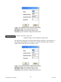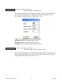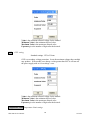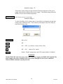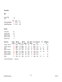
1
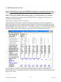
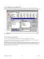
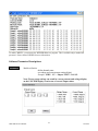
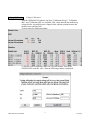
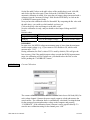
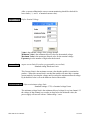
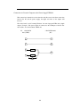
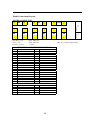
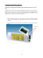
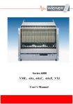
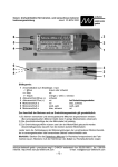
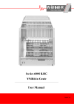
VME 602X – Series
Service Manual
UEP 6000 Service Manual
1
10/16/06
General Remarks
The only purpose of this manual is a description of the product. It must not be interpreted a declaration of
conformity for this product including the product and software.
W-Ie-Ne-R (WIENER Plein & Baus Corp. and Plein & Baus GmbH) revises this product and manual without
notice. Differences of the description in manual and product are possible.
W-Ie-Ne-R excludes completely any liability for loss of profits, loss of business, loss of use or data, interrupt of
business, or for indirect, special incidental, or consequential damages of any kind, even if W-Ie-Ne-R has been
advises of the possibility of such damages arising from any defect or error in this manual or product.
Any use of the product which may influence health of human beings requires the express written permission of
W-Ie-Ne-R.
Products mentioned in this manual are mentioned for identification purposes only. Product names appearing in
this manual may or may not be registered trademarks or copyrights of their respective companies.
No part of this product, including the product and the software may be reproduced, transmitted, transcribed,
stored in a retrieval system, or translated into any language in any form by any means with the express written
permission of W-Ie-Ne-R.
W-Ie-Ne-R declines all responsibility for any damage of the VME crate or part of it and / or crate or of any
equipment used inside or outside of the crate caused by improper use of it or operation / action of unauthorized
not-qualified personal. This Service manual is only for qualified and authorized persons.
UEP 6000 Service Manual
2
10/16/06
UEP 6000 Power Supply Configuration and Test Software
The MUH6000 program is a software for Windows based PC’s to test and set-up the configuration and
calibration of WIENER power supplies of the UEP 6000 series. The communication is via RS232 using the
WIENER UEP 6000 adapter cable.
WIENER Plein & Baus Corp. / GmbH is not responsible for any damage of the power supply and / or crate or of
any module inside the crate caused by changing the factory prepared configuration and calibration of the power
supply. The test and diagnostic box and MUH 6000 software has to be used by authorized and qualified
personnel only!
To protect the UEP 6000 power supply for unauthorized access there is a hardware write protection. This write
protection prevents unauthorized users from changing the nominal voltages, calibration values, and current
limits. To override this protection you most have the Flash6.exe program.
!!!!! DANGER - HIGH VOLTAGE !!!!!
For authorized, qualified service personnel only
This power supply uses high voltage up to 400V inside. Unauthorized persons are not allowed to open the UEP
6000 power supply or to connect them to AC mains or use them without completely closed chassis.
Do not open while connected to AC mains, unplug first from the wall outlet.
After opening the power supply discharge first all capacitors of primary side (AC input module and 3-pin
primary distribution cables/connectors) as well as of the MUH AUX power supply with a load resistor.
In case of questions please contact:
W-IE-NE-R Plein & Baus Ltd., Dr. A. Ruben
300 East Auburn Ave.
Springfield, Ohio 45505
Phone : (937) 324 2420
FAX : (937) 324 2425
E-mail: [email protected]
URL : http://www.wiener-d.com
UEP 6000 Service Manual
3
10/16/06
1) MUH 6000 installation and start
Please copy the RS232.DLL as well as the WIENER.INI configuration file to the Windows directory of your
computer. Before starting the program make sure that the power supply is not connected to the AC-line. Connect
the UEP 6000 power supply to the serial port of the PC via the WIENER adapter cable. DO NOT CHANGE
THIS CONNECTION WHILE THE POWER SUPPLY IS CONNECTED TO AC MAINS!!!
Change the COM setting to fit your setup the WIENER.INI file by changing COM2 to the correct
COM port of the used serial port.
Connect the power supply to the AC mains line.
During program start the software automatically detects and connects to the power supply if the
RS232 connection is available through the selected COM port. The main window displays the power
supply setting and status as shown in the following example. In case of any communication problem
(wrong COM port, cable connection not ok, …) the „RS232 connection is interrupted” error message is
shown. The main window shows further the power supply ID (serial number or part number).
The UEP 6000 power supply can be switched on or off by mouse clicking on the POWER ON /
POWER OFF line or by selecting the menu item. After switching on all power supply channels should
show an „OK“ status.
UEP 6000 Service Manual
4
10/16/06
2) Power supply operation and configuration file
Please save the present configuration of the connected power supply as a file to hard or floppy disk before
changing any item. It is recommended to keep all configuration files to allow an easy restore of the configuration
data at a later time.
3) Power supply set-up and calibration
To access any (available) parameter point the cursor on it and click with the left mouse button.
If you do not see the parameters mentioned below, click on the “Configuration” menu. This will bring up a
window that allows you to choose which parameters are shown.
WIENER Plein & Baus Corp. / GmbH is not responsible for any damage of the power supply, VME crate or of
any module inside the crate caused by changing the factory prepared configuration and calibration of the power
supply. To protect the UEP 602X power supply for unauthorized access there is software write protection. All
parameters that are gray are write protected.
UEP 6000 Service Manual
5
10/16/06
To enable "WRITE „ you must use the WIENER flash6.exe program. This is available only to authorized
personnel. Please contact WIENER for more information.
Software Parameter Descriptions:
CHANNEL
Module definition
define channel name
set voltage and current range setting (digits)
Example: STBY: 31V / Ampere XXXX. / Volt XX.
Note: Wrong range settings can result in a wrong current and voltage display
on the UEL 6020 display even in case of correct output values.
UEP 6000 Service Manual
6
10/16/06
Voltage Calibration
Voltage Calibration
With the UEP6000.EXE software, the lines "Calibration (Kovp)", "Calibration
(Ku)" and "Calibration (Kf)" are available. This values describe the module ovp
voltage divider, the module sense voltage divider, and the relation between the
module coarse and fine DAC.
Typical values for different modules:
To find the correct calibration values for a specific module, click in the
UEP6000.EXE to the Ku value. Then the following window is displayed:
UEP 6000 Service Manual
7
10/16/06
Set the Ku and Kf values to the table values of the module that is used, click OK,
and click to the Ku value again. Then click on the CALIBRATE button. An
automatic calibration is started. Now enter the real output voltage (measured with a
voltmeter) into the "measured Voltage" field. Hit the ENTER Key or click on the
CALIBRATE button again. Ready.
Now you have the calibrated values for Ku and Kf. By comparing the Ku value with
the table above, you could see which module you have got.
Click to the Kovp value and change it to the table value.
Now the calibration is ready, and you should set the Output Voltage and OVP
levels.
Default values
Value
Maximum
Output Voltage [V] The voltage the customer wants Umax (module table)
125% of the Output Voltage
OVPmax (module table)
OVP[V]
REMARKS
In some cases, the MUH6 voltage measurement range is lower than the maximum
module output voltage. (e.g., if you connect a 24V module to U0, which could
measure max. 7.5V).
During calibration, the DACu value of 255 is used by default. (This will give the
best accuracy). But if the module output voltage exceeds the MUH6 measurement
range, the calibration will fail. In that case, you should reduce the DACu value
before pushing the "CALIBRATE" button.
Cal I-Monitor
Current Calibration
The current calibration should be done for a current limit close to full load (90%) for
each voltage channel. Connect the power supply output to a load and measure the
actual current. The calibration factor is automatically calculated if writing the data
for the measured current and monitor voltage to the computer and pressing
“CALIBRATE”. If the calibration factor is known it can be typed in directly. To
store the new calibration setting for the channel press “OK”.
UEP 6000 Service Manual
8
10/16/06
After a current calibration the correct current monitoring should be checked for
lower loads ( ½ and ¼ of nominal current value).
Output Voltage Define Nominal Voltage
Value is the nominal voltage of the voltage channel.
Minimum Value is the minimum allowed value for the nominal voltage.
Maximum Value is the maximum allowed value for the nominal voltage.
Exponent gives the number of digits after the decimal.
Current Limit
output current limit (Secondary programmable current limit)
Standard setting: Hardware Limit
This Current Limit is the maximum current value that the module is permitted to
produce. When this current limit is reached the module will enter into a constant
current mode by lowering the voltage until it reaches the minimum allowed voltage.
By default this value is set to the hardware limit of the module.
Monitoring:Umin
Software minimum voltage limit
Standard settings: 97.5% of nominal voltage Unom
The minimum voltage limit is the minimum allowed voltage for a given channel. If
the voltage of that channel ever reaches or drop below the minimum value, the
power supply will turn off with an “Undervoltage “ error.
UEP 6000 Service Manual
9
10/16/06
Value is the minimum allowed voltage for the channel.
Minimum Value is the minimum allowed value.
Maximum Value is the maximum allowed value.
Exponent gives the number of digits after the decimal.
Monitoring:Umax
Software maximum voltage limit
Standard settings: 105% of nominal voltage Unom
The maximum voltage limit is the maximum allowed voltage for a given channel. If
the voltage of that channel ever reaches or exceeds the maximum value, the power
supply will turn off with an “Overvoltage “ error.
Value is the maximum allowed voltage for the channel.
Minimum Value is the minimum allowed value.
Maximum Value is the maximum allowed value.
Exponent gives the number of digits after the decimal.
UEP 6000 Service Manual
10
10/16/06
Monitoring:Imin
Software minimum current limit
Standard settings: No minimum (0)
The minimum current limit is the minimum allowed current for a given channel. If
the current for that channel ever reaches or drop below the minimum value, the
power supply will turn off with an “Undercurrent “ error.
Value is the minimum allowed current for the channel.
Minimum Value is the minimum allowed value.
Maximum Value is the maximum allowed value.
Exponent gives the number of digits after the decimal.
Monitoring:Umax
Software maximum cuurent limit
Standard settings: 100% of Hardware Limits
The maximum cuurent limit is the maximum allowed current for a given channel. If
the cuurent of that channel ever reaches or exceeds the maximum value, the power
supply will turn off with an “Overcurrent “ error.
UEP 6000 Service Manual
11
10/16/06
Value is the maximum allowed voltage for the channel.
Minimum Value is the minimum allowed value.
Maximum Value is the maximum allowed value.
Exponent gives the number of digits after the decimal.
OVP
OVP setting
Standard settings: 125% of Unom
OVP is a secondary voltage protection. It sets the maximum voltage that a module
may produce. If the module ever detects a value greater than OVP it will turn off
the power supply with an “Overvoltage” error.
Value is the maximum allowed voltage for the module.
Minimum Value is the minimum allowed value.
Maximum Value is the maximum allowed value.
Exponent gives the number of digits after the decimal.
Temperature Limit Temperature Limit settings
UEP 6000 Service Manual
12
10/16/06
Standard settings: 127
Temperature Limit settings sets the maximum internal temperature of the power
supply module before turning off the power supply. The default settings allow the
module to run to the maximum temperature.
Power-on Delay Delay between power-on and ramp
Standard settings: 0
To allow flexibility of the voltage ramp, it is possible to set channels to begin their
voltage ramp at different times. This is done by delaying the start of the ramp by
some time in steps of ms.
Temperature
OK or Fail
Status
OK
Power
ON - OFF
by software ( mouse click or <P>)
AC
OK - Fail
(status of AC mains)
Trip off
Enable - Disable (temperature and OVP control enabled - disabled)
WARNING
Disable TRIP OFF only if necessary, don’t leave the power supply with TRIP OFF disabled! The
power supply and crate or modules in the crate can be damaged in case of error conditions
without enabled automatic trip off protection.
UEP 6000 Service Manual
13
10/16/06
Complete Test Instruction for UEP 6000
1. Visual test
Power Supply surface ok?
Final set-up ok?
Cable mounting ok?
2. HV-Test
2.4kVDC: AC-mains - PE
Short circuit test @ 50V DC: Output - PE.
- since 1998 sticker: HIGH VOLTAGE TESTED
- high voltage test has to be repeated if there are changes of the power
configuration or set-up
3. Put into Operation
(with complete function control)
Configuration, calibration (trimmer) , current measurement adjustment ( I-Mon )
Measurement of current limit (short circuit current)
- since 1998 sticker CALIBRATED
- sequence of test steps according to test procedure
4. Burn In
Long time test with full load and multiple on / off
(
- since 1998 sticker LONG TIME TESTED
- Attention: do not exceed the maximum total power (mains fuse!)
- in case of parallel working AC inputs take care for equal load for both
- power supply levels
5. Mechanical Set-up
a) Mounting screws OK?
b) Power terminal contacts OK?
c) Mount missing mechanical parts and check all screws
d) test fitting of power supply into VME bin
6. End check
to be done with protocol
- since 1998 sticker END CONTROLLED
- sequence of test steps as for 3. Put into Operation
- write protection enabled?
- visual check for stickers and device label
UEP 6000 Service Manual
14
10/16/06
Test Procedure Sequence UEP6000
1. Test AC input switch AUTO/FIX for Power Supplies with auto range AC inputs
- AUTO : feed 3V DC in AC mains cable, measure current (typically 0,08mA)
- switch to 115V ( current typically 0,52mA).
- prepare for delivery with switch position to AUTO with locking and sticker
2. Start Power Supply Operation:
- disable Write protection (jumper), connect power supply to IBM-PC (RS 232)
- feed AC mains in power supply
- start software UEP 6000, create or copy configuration file
- if the fan tray unit is connected to the power supply the write protection
jumper has to be disabled during start for power supply software version
MUH 1.00
3. General behavior / settings
Main configuration OK ?
RS 232 OK ?
Channel? Module-current/limit? Module OVP? Module Unom?
min/max Voltage?
4.Test each Voltage Channel
Check adjustment Master-Slave Imon and CV. Coding for slave
U-nom under full Load : fine tuning ? display OK ? Noise and Ripple OK ?
Current calibration for 3 load values (full, half, no load):
I-nom
Full load
Half Load
No Load
Display Fan tray
?
?
?
?
?
?
Signal
I-nom
At this time proof static regulation (U) ( Sense wiring)
T-Hold after AC-Fail, U-Dynamic, T-Recovery have been checked within
power module test
7. Adjustments
Voltage Error adjusted?
Current Error checked with different current values?
Reference Table for Test and Adjustment of UEP 6000
UEP 6000 Service Manual
15
10/16/06
CHANNEL
Module selected
Are all installed voltage channels present?
Example: STBY: 31V / Ampere XXXX. / Volt XX.
Cal I-Monitor
Calibration
measure current
Enter measured current and hit “CALIBRATE”
Output Voltage output voltage
Nominal voltage for the channel
Current Limit
The max current allowed for that channel (constant current)
maximum current
Monitor U-min minimum voltage
90% of nominal voltage
Monitor U-max maximum voltage
112.5% of nominal voltage
Monitor I-min
minimum current
Generally 0
Monitor I-max
maximum current
112.5% of nominal expected current (“Overcurrent” error)
Module OVP
maximum voltage
125% of nominal voltage
Power on Delay ramp Delay
Delay, in ms, between power-on and start of voltage ramp
Temperature
OK or Fail
Status
OK
Power
ON - OFF
by software ( mouse click or <P>)
AC
OK - Fail
(Status of AC mains at Elko)
Trip off
Enable - Disable
UEP 6000 Service Manual
16
10/16/06
UEP 6000 Module Replacement Instructions
In troubleshooting WIENER crates it is very useful to substitute Fan trays and power supplies from
working crates into the crate which is problematic, this is often the best way to determine which
component (fan tray, power supply, or crate) is causing the failure. It is also useful to place the power
supply on a bench top and use the UEP6000 software to troubleshoot power supplies.
MNPFC-16
The MNPFC-16 is the primary rectifier for the UEP6000 power supply. Common symptoms of a
power supply with a faulty are MNPFC are:
• No indication that the power supply is operating.
• The green LED on the board is not lit. (Visible with case closed).
• No “click” when power supply is plugged in.
• No internal primary DC voltage from MNPFC-16 (385VDC)
If the MNPFC is found to be the problem, the following steps should be taken to replace it:
• Disconnect A/C power and remove power supply from the VME crate.
• Remove the top cover from the power supply and discharge capacitors
• Remove the side panel on which the MNPFC is mounted, including the nuts with which the
module is mounted.
• Disconnect the A/C wires (Brown & Blue) as well as the flat ribbon cable and DC connector
from the module.
• Installation is the reverse of removal.
• After replacing the cover, connect the A/C input and ensure that functionality is OK.
UEP 6000 Service Manual
17
10/16/06
MEH/MDH
The MEH/MDH modules are the secondary rectifier modules that produce the voltages used by the
VME crate. Common symptoms of a faulty MEH/MDH module are:
• An over/under voltage error for a certain channel (On UEL display or via UEP6000
software).
• The power supply will start up but turn itself off quickly.
If an MDH/MEH module is found to faulty the following steps should be taken to replace it (valid only
for standalone modules):
• Disconnect A/C power and remove power supply from the VME crate.
• Remove the top cover from the power supply and discharge capacitors
• Determine which power module is faulty. This is done by locating the right channel along the
top of the MUH board and following the control cable to the correct module.
• Disconnect the power cables and the flat control cable(s) from the module.
• Remove the screw that holds the module to the case.
• Slide the module forward and remove the module.
• Installation is the reverse of removal.
• Calibrate the voltage and current measurements
• After replacing the cover, connect the A/C input and ensure that functionality is OK.
UEP 6000 Service Manual
18
10/16/06
MUH
The MUH module is the microprocessor control board for the power supply. Common symptoms of a
faulty MUH module are:
• No function although internal operating voltage is present (385VDC).
• Under/over voltage error for 1 or more voltage channel.
• No remote interface (errors when connected to UEP6000 software).
If an MUH module is thought to be faulty the following steps should be taken to replace it:
• Disconnect A/C power and remove power supply from the VME crate.
• Remove the top cover from the power supply and discharge capacitors
• Remove the side panel next to the MUH module.
• Disconnect the flat ribbon control cables, recording where they were plugged in.
• Disconnect the sense, CAN, DC, and control cables.
• Remove the 25-pin D-sub connector to gain access to the screws holding the MUH board to
the chassis.
• Remove the module from the crate.
• Remove the EEPROM from the module and place it into the new MUH module. This will
transfer the channel calibration information.
• Installation is the reverse of removal.
• Once power supply cover is replaced, check that the current and voltage calibrations are
correct.
UEP 6000 Service Manual
19
10/16/06
UEP 6000 Channel Calibration
Voltage Calibration
Voltage calibration values vary depends on what kind of module you are calibrating and which
nominal voltage you wish that channel to have. To calibrate a power supply channel:
• Connect the power supply to a PC and start the UEP6000 software
• Start Flash6.exe and turn off “write disabled”
• Click on “Voltage OVP” and enter the value specified in the table below.
• Turn the power supply on and measure the channel voltage.
Current Calibration
Correct current calibration ensures that the power supply reports the correct current readings. To
calibrate the current values for a given channel, the following steps should be taken:
• Connect the power supply to a PC on which the UEP600 software is installed via a
appropriate adapter cable.
• Connect a current sink to the channel that you wish to calibrate.
• Connect A/C power and ramp the current up to 90% of the channel maximum.
• Click on “Calibration [I-monitor]” and enter the measured current.
• The UEP6000 will calibrate the current monitor and should now report the same value as the
measured current.
The calibration procedure above only works for master modules. If you have two or more modules
running in co-operation with each other, you will have to do a master-slave calibration. Please contact
a WIENER representative for guidance with this task.
UEP 6000 Service Manual
20
10/16/06
Module-Data
MRP
Resistor DAC[k]
R6[k]
Version .B2 and below
Version .B3 and above
12
20
R5[k]
alpha
75 0,81308
750 0,97442
Kf
7533
860
Modules
Uref(U) [10mV]
Uref(OVP) [10mV]
MRP: R13, R14 [k]
MRP: R17, R18 [k]
MRP: R4, R12 [k]
Module Type
5V-MEH, <= Index A5
5V-MEH, >= Index A6
MEH10
MEH12, <= Index A1
MEH12, >= Index A2
MDH7-15, >= Index A0
MDL12/24, (MEH24)
MEH48
510
250
10
20
10
R4,R12
[kOhm]
13,3
22,1
33,2
61,9
56,2
56,2
110
221
DACovp = U[V]*Kovp/655.36
Modul-DAC-Values.xls
MRP :B2
Ku
Poti[mV]
34729
4,34
25208
5,98
18731
8,04
11254
13,39
12223
12,33
12223
12,33
6743
22,34
3503
43,01
MRP :B3
Ku
Poti[mV]
28978
0,59
21034
0,82
15630
1,10
9391
1,83
10199
1,69
10199
1,69
5627
3,06
2923
5,88
Umax R9,R10
[V]
[kOhm]
5,92
27,4
8,15
43,2
10,97
56,2
18,26
82,5
16,82
82,5
16,82
82,5
30,48
133
58,67
274
Kovp
24492
15534
11941
8134
8134
8134
5046
2449
OVPmax R5/8
R6/7
GND-floating
[V]
[V]
6,82
1
0
12,0
10,76
1
0
12,0
14,00
2,21
2,21
24,0
20,54
2,21
2,21
24,0
20,54
2,21
4,75
37,8
20,54
33,12
1
0
12,0
68,23
4,75
30
87,8
alte Module
21
27.03.03
Connection of a Personal Computer to the Power Supply UEP6021
This connection is intended to service functions only. Because of the direct connection
between the PC and the power supply, the ripple and noise of the outputs will
increase!
The needed stuff is an PC running Windows, the control program UEP6 and a simple
adapter (“Dongle”). The power supply is connected to the COM port of the PC. For
more details, view the document *00461.A0.
X3, 9 Pin DSUB
male (UEP6)
9 Pin DSUB female
(PC)
3
2
8
3
7
1 kOhm
5
6
1 kOhm
100nF
22
PL6021 Connection Diagram
POWER CONNECTOR
17
-
14
-
11
-
8
-
5
-
2
-
U6
U5
U1
U3
U4
U0
16
+
13
+
10
+
7
+
4
+
1
+
Pin 10,11,13...18:
Pin 1...9+12:
Polarity: + positive
6mm, 120A max.
8mm, 240A max.
- negativ
3
+
U0 to U7 = standard pinning only!
SENSE/SIGNAL CONNECTOR D-SUB 37
19
TEMP RETURN
37
TEMP 0
18
TEMP 1
36
TEMP 2
17
TEMP 3
35
TEMP 4
16
TEMP 5
34
TEMP 6
15
TEMP 7
33
BIN EEPROM: IIC SDA
14
BIN EEPROM: IIC SCL
32
BIN EEPROM:+5V
13
VME LOGIC: SYSRESET
31
BIN EEPROM: GND
12
VME LOGIC: ACFAIL
30
VME LOGIC GND
11
VME LOGIC: SYSFAIL
29
U0 SENSE -
10
U0 SENSE + (VME: +5V)
28
VW SENSE (reserved)
9
VW SENSE (reserved)
27
VX SENSE (reserved)
8
VX SENSE (reserved)
26
U4 SENSE +
7
U4 SENSE -
25
U7 SENSE +
6
U7 SENSE -
24
U2 SENSE -
5
U2 SENSE + (VME: 48V)
23
U6 SENSE +
4
U6 SENSE -
22
U1 SENSE -
3
U1 SENSE + (VME: +12V)
21
U5 SENSE +
2
U5 SENSE – (VME: -12V)
20
U3 SENSE -
1
U3 SENSE + (VME: +3.3V)
FAN/CONTROL CONNECTOR D-SUB 9
5
Spare
37
6
-
D-SUB
9
+
U7
9
12
-
U2
D-SUB
15
+
18
-
CAN_H
9
CAN_L
4
CAN GND
8
RXD
3
TXD
7
+15V (for fan only)
2
+15V (for fan only)
6
-15V (for fan only)
1
-15V (for fan only)
23
WIENER VME Crate Temperature Sensors
24
VME 6000 Series Bin EEPROM configuration
WARNING!!! Changing the BIN EEPROM setting could damage modules in the VME
crate.
WIENER 6000 series VME crates contain an EEPROM which contains data about what power
supplies to accept. This prevents users from accidentally plugging in power supplies that could
damage modules within the crate. If the crates function is changed and the EEPROM needs to be
reprogrammed, it can be done by following the steps below.
1. Remove the fantray from the crate. This will give you access to a subD 9 pin connector.
Plug one end of a WIENER power supply adapter into the connector, connect the other a
computer.
2. Insert a jumper on the write protect pins for the EEPROM. The pin locations are shown
below.
Write jumper
25
3. Open the UEP6000 program. The current bin settings should now be visible as
highlighted below.
4. If screen does not show BIN configuration, select configuration and highlight these lines:
26
5. Select bin parameter to be changed and enter new value
6. Changes are saved automatically when you hit OK
27
UEL6000 Ethernet Firmware-Update
The UEL6000 Firmware is stored in a FLASH ROM and can be updated via the RS232
connector.
Necessary equipment:
- Computer with RS232 interface, running Microsoft Windows (98 or above)
- A patch cable to connect the UEL6000 with this computer
- This software
Installation Steps:
1. Unzip the UEL6402.zip to your had disk.
2. Connect the computers COM port to the UEL6000
3. Switch the UEL6000 into “Load Update” mode
The “Load Update” mode is a submenu of the “RS232 Configure” menu of the
configuration menu.
You will use the following switches of the fan tray:
P▲
P▼
M▲
M▼
Push “Power” switch up(ON)
Push “Power” switch down (OFF)
Push “Mode Select” switch up
Push “Mode Select” switch down
Steps to get into the “Load Update” mode:
Description
switch the crate off
P▼
Display
________________
enter configuration menu
M▲(push and hold), P▲
Config: Wait
hold both switches up
Config: Wait...
after 4 seconds you can
Config: Ready !
release the switches
+5V0 0.01V
Now select the “RS232
Configure” menu
Enter this menu
Switch
0A
M▲ or M▼ (until right menu RS232 Configure
is displayed)
Baudrate: 115.2k
P▲
Select submenu “Firmware”
M▲ or M▼ (until right menu UEL6000 Firmware
is displayed)
UEL6000 4.02
Enter submenu
P▲
Load Update: No
Change to yes
M▲
Load Update: Yes
Accept settings and enter
update mode
P▲
Scanning RS232..
4. Run the upload software on the computer
Open a command window, change to the folder of the unzipped file.
At the prompt enter the command
C:UEL6402> F28xxConsole.exe -v -p com1 -i UEL6E.4.02.out
Plein & Baus GmbH
1 UEL6000E Firmware Update, 15 Jun 2004
28
Replace “com1” with the COM port which you are using.
The software now connects to the UEL6000, the following is displayed:
Installed output message callback
Loading F2810SerialFlash.out
Entry point 0x003f8000
Section Address = 0x003f8000, Number of words =
3235.................................................................
Section Address = 0x003f8ca3, Number of words = 4.
Section Address = 0x003f8ca7, Number of words = 84..
Section Address = 0x00000792, Number of words = 67..
.Boot code loaded
Connected to \.\COM1 at 5 baud
Target is programmed with "UEL6000 4.01"
Erase the flash ?(y/n) y
This is the last chance to interrupt the update. If you say 'y' here, the UEL6000 flash is
erased. Next messages are:
Erase the flash.
Program the flash ?(y/n) y
You should say 'y', too. If not, you have got an empty flash which can only be
reprogrammed at the factory.
Program
Section
Section
Section
Section
Section
Section
Section
Section
Section
Section
Section
Section
Section
Section
Section
Section
Section
Section
Section
Section
UEL6E.4.02.out
Address = 0x003e8000, Number of words = 3676
Address = 0x003e8e5c, Number of words = 253
Address = 0x003e8f59, Number of words = 21
Address = 0x003e8f6e, Number of words = 629
".stack" IGNORED (vaddr=0x8200 out of flash area)
Address = 0x003e91e3, Number of words = 3
".args" IGNORED (vaddr=0x1fc out of flash area)
"" IGNORED (vaddr=0x340 out of flash area)
".trace" IGNORED (vaddr=0x47c out of flash area)
Address = 0x003e91e6, Number of words = 256
Address = 0x003e92e6, Number of words = 32
Address = 0x003f7ff6, Number of words = 2
Address = 0x003f7ff8, Number of words = 8
Address = 0x003f7f80, Number of words = 118
Address = 0x003e9306, Number of words = 23754
Address = 0x003eefd0, Number of words = 3628
Address = 0x003f7f70, Number of words = 16
Address = 0x003efdfc, Number of words = 30
Address = 0x003efe1a, Number of words = 12
Address = 0x003efe26, Number of words = 1539
Verify UEL6E.4.02.out
Section Address = 0x003e8000, Number of words = 3676
Section Address = 0x003e8e5c, Number of words = 253
Section Address = 0x003e8f59, Number of words = 21
Section Address = 0x003e8f6e, Number of words = 629
Section ".stack" IGNORED (vaddr=0x8200 out of flash area)
Section Address = 0x003e91e3, Number of words = 3
Section ".args" IGNORED (vaddr=0x1fc out of flash area)
Section "" IGNORED (vaddr=0x340 out of flash area)
Section ".trace" IGNORED (vaddr=0x47c out of flash area)
Section Address = 0x003e91e6, Number of words = 256
Section Address = 0x003e92e6, Number of words = 32
Section Address = 0x003f7ff6, Number of words = 2
Section Address = 0x003f7ff8, Number of words = 8
Plein & Baus GmbH
2 UEL6000E Firmware Update, 15 Jun 2004
29
Section
Section
Section
Section
Section
Section
Section
Address
Address
Address
Address
Address
Address
Address
=
=
=
=
=
=
=
0x003f7f80,
0x003e9306,
0x003eefd0,
0x003f7f70,
0x003efdfc,
0x003efe1a,
0x003efe26,
Number
Number
Number
Number
Number
Number
Number
of
of
of
of
of
of
of
words
words
words
words
words
words
words
=
=
=
=
=
=
=
118
23754
3628
16
30
12
1539
Press [Enter] key to exit
OK, the update is ready. Now restart the crate by removing the mains cord.
If there are new data items in the EEPROM, after the restart they will be initialized. You
have to acknowledge the “CHECKSUM xxxx” messages by pushing the “SYSRES” button
at the fan tray.
Plein & Baus GmbH
3 UEL6000E Firmware Update, 15 Jun 2004
30
UEL6 Ethernet Pin Description
1.
CAN-Bus (X1, X2)
RJ45
Pin
1
2
3
4
5
6
7
8
Signal
CAN-H
CAN-L
GND
n.c.
n.c.
reserved
GND
n.c.
Comment
This is the standard CIA pinning. Both connectors are wired in parallel, so it’s easy to connect many crates in a daisy-chain.
2.
RS232 (X2)
RJ45
Pin
1
2
3
4
5
6
7
8
Signal
n.c.
n.c.
n.c.
GND
RXD
TXD
CTS
RTS
Comment
Output
Input
Output
Input
This is the standard RS232D DCE pinning. Connection to DTE (e.g. computer) with a 1:1-cable.
3.
Ethernet (X4)
RJ45
Pin
1
2
3
4
5
6
7
8
Signal
TX+
TXRX+
GND 1
GND 1
RXGND 2
GND 2
Comment
75 Ohm
75 Ohm
This is the standard NIC configuration. You need a 1:1-cable to connect a to a HUB, or a cross-over cable to connect to another
NIC (e.g. a computer)
31
32
33
34
35
R3
C2
C10
S1
S2
U1
S3
S4
U2
R4
D5
U3
U4
S5
U5
D6
D7
U6
U8
U7
S6
D8
C12 C3
C13 C4
C9 C8 C7 C6
D3 R2 D4
C1
C5
D2 R1
D9 C11
S7
X6
C10, C11:
max. Bauhöhe 7mm, sonst legen
w-ie-ne-r Plein & Baus GmbH
D-51399 Burscheid
+49-2174-678-0
www.wiener-d.com
Title
SG;I/O-Complete
Number
Rev
1407053
36
Plot
Tue Jul 13, 2004 Date
Filename
10.04.03 Drawn by
io-neu.PCB
A5
Fri
C12
100N/63V
C9
2N2/50V
C13
2N2/50V
100P/63V
100P/63V
C8
100P/63V
C6
X6:F
X6:D
X6:C
LED:3GN:F:S
D2
LED:3RT:F:S
D3
LED:3RT:F:S
D4
LED:5GN
D9
LED:3GE:F:S
D6
LED:3GN:F:S
D5
LED:3GE:F:S
D7
LED:3RT:F:S
D8
5
100N/63V
100N/63V
C5
100N/63V
C3
X6:A
100N/63V
C1
1
100N/63V
C2
X6:B
22u/50V
C4
2
22u/50V
C11
X6:E
C10
C7
6
4
3
w-ie-ne-r Plein & Baus GmbH
D-51399 Burscheid
+49-2174-678-0
Title
37
www.wiener-d.com
I/O-Modul
Sheet1
Number
Rev
1407053
Plot
Thu Jun 24, 2004 Date
Filename
A5
02.April2003 Drawn by
io-neu.sch Sheet
Fri
1
of 1
C1 nicht
bestücken!
10
X5
6
1
1
1
X8
X7
6
w-ie-ne-r Plein & Baus GmbH
D-51399 Burscheid
Title
+49-2174-678-0
UEL6000 CPU with Ethernet
Number
38
Plot Wed Mar 10, 2004 Date
Filename
www.wiener-d.com
1464212
10.03.2004 Drawn by
uel6e.pcb
Rev
A3
GE
X8:D
100N/16V
4
RS232_TXD
RS232_CTS
RS232_RTS
1.00k/0.125W
X_CS
X8:F
6
X8:E
5
R67
10.0k/0.125W
B_SOMI
R72
GND
V3.3_RS
R73
C77
R70
GND
GND_RS
X_SOMI
V3.3
10.0k/0.125W
GND
R13
5
15.0k/0.125W
15P/50V
X7:E
3.30k/0.125W
UEP_CANH
CANH
8
X5:H
UEP_CANL
CANL
R7
GND
3.30k/0.125W
CTS
R5
R1
Q1
RTS
V30
GND_RS
CANGND
GND
1.80k/0.125W
UEP_CANGND
1.80k/0.125W
R8
X5:G
1.80k/0.125W
R2
7
R10
R21
D3
10.0k/0.125W
GND
V3.3
BC857C
R19
GND_RS
BC857C
R18
X5:I
15.0k/0.125W
Die Drosseln waren bisher immer gebrückt!
9
Q2
10.0k/0.125W
BC847C
V3.3
Connection to CAN
6
33.0k/0.125W
X5:F
Q4
SCIRXDA
R17
V3.3_RS
3.30k/0.125W
74ACT14PW
C76
15.0k/0.125W
15P/50V
R69
R27
X_SIMO
R71
R12
220P/50V
R26
BC847C
GND_RS
RS232_RXD
SCITXDA
UEP_TXD
Q9
R64
1.00k/0.125W
3.30k/0.125W
4
V3.3_RS
100N/16V
3
B_CS
X_CLK
C6
6
3
1.00k/0.125W
100N/16V
C11
X7:F
R86
IO_SOMI
GND
C15
R34
B_SIMO
8
74ACT14PW
U10:B
IO_LOAD
4.70k/0.125W
33.0k/0.125W
R25
33.0k/0.125W
R24
BC847C
3.30k/0.125W
4
1.00k/0.125W
SPI_SOMI
Q6
SCITXDB
X7:D
9
10.0k/0.125W
V30
LL103A
6
12
74ACT14PW
U10:D
R87
74ACT14PW
Connection to MUH
D4
R88
X8:C
RS232 Transceiver
DTE Pinning (we are DCE <-> 1:1-Cable)
11 Bauteile (0805+SOT23) weniger, wenn statt MAX232 MAX3520 verwendet wird!
15.0k/0.125W
5
SPI_CS
13
B_CLK
1.00k/0.125W
IO_SIMO
74ACT14PW
U10:C
3
1
2
Q3
2
X7:C
X8:A
X8:B
1U0/50V
IO_CLOCK
74ACT14PW
U10:A
SPI_SIMO
V5.0
U10:F
1.00k/0.125W
10
1
GND
BC847C
11
SPI_CLK
1
2
C5
V5.0
U10:E
X7:A
X7:B
C9
GND
Connection to external IF (HCT!!)
100N/16V
C10
Connection to I/O (HCT!!)
SCIRXDB
LL103A
R23
GND_RS
39
1.80k/0.125W
GND
GND
1.80k/0.125W
R20
V3.3
CANRX
1.80k/0.125W
R15
GND
CANTX
R65
BC847C
R9
10.0k/0.125W
100R/0.125W
UEP_RXD
R22
X5:E
1.00k/0.125W
5
V3.3_RS
Q5
w-ie-ne-r Plein & Baus GmbH
D-51399 Burscheid
+49-2174-678-0
Interface
Number
GND
www.wiener-d.com
UEL6000 CPU with Ethernet
Title
Plot
Wed Mar 10, 2004
Filename
Rev
14644212
Date
10.03.2004
Drawn by
uel6e.sch Sheet
A3
Koe/Ge
1
of 4
100N/16V
C40
100N/16V
C21
100N/16V
C65
100N/16V
C52
100N/16V
C43
100N/16V
C49
100N/16V
C64
100N/16V
C22
100N/16V
C23
100N/16V
C35
100N/16V
C66
100N/16V
C42
100N/16V
C20
C38
100N/16V
C39
C45
100R/0.125W
ADC0
ADC1
ADC2
ADC3
ADC4
ADC5
ADC6
ADC7
ADC8
ADC9
ADC10
ADC11
V3.3
ADC12
R66
C72
R59
ADC13
ADC14
ADC15
ADC_LO
47U/10V/600mR
C71
V3.3
10.0k/0.125W
24.9k/0.125W
10.0k/0.125W
R48
GND
47U/10V/600mR
V3.3
47U/10V/600mR
C29
R52
R45
V1.8
1.80k/0.125W
C50
100N/16V
100N/16V
C51
SPI_SIMO
SPI_SOMI
SPI_CS
SCITXDA
CANTX
100N/16V
100N/16V
C63
100N/16V
C62
CANRX
B_CLK
V3.3A
GNDA
B_CS
B_SIMO
0R0/0.125W
WP
SCL
INTE
C18
SDA
DATA
D0
GND
DATA
RESET
15P/50V
D1
D2
D3
C19
D4
D5
GND
SDA
CTS
AEN
RESET
D6
D7
15P/50V
D8
D9
D10
TMS
D11
TRST
D12
TDI
D13
D14
V3.3
D15
TDO
TCK
TCK
GND
EMU0
EMU1
GND1
GND
40
GND
1.80k/0.125W
GND
IOW
INDEX /DATA
10.0k/0.125W
R39
SCL
GND
RTS
V3.3
WP
GND
IOR
V3.3
GND
GND
25MHZ
R47
R16
R6
10.0k/0.125W
GND
SCIRXDB
1.00k/0.125W
R4
SCITXDB
FAN_PWM2
10.0k/0.125W
R11
FAN_PWM1
V3.3
R68
B_SOMI
10.0k/0.125W
R46
C47
SCIRXDA
100N/16V
C60
C54
GND
47U/10V/600mR
SPI_CLK
V3.3
47U/10V/600mR
10.0k/0.125W
C32
RESET
GND
GND1
V1.8
100N/16V
V3.3
100N/16V
V5.0
X6:1
X6:2
X6:3
X6:4
X6:5
X6:6
X6:7
X6:8
X6:9
X6:10
X6:11
X6:12
X6:13
X6:14
1
2
3
4
5
6
7
8
9
10
11
12
13
14
JTAG Interface
w-ie-ne-r Plein & Baus GmbH
D-51399 Burscheid
+49-2174-678-0
www.wiener-d.com
UEL6000 CPU with Ethernet
Title
Processor
Number
Plot
Wed Mar 10, 2004
Filename
Rev
14644212
Date
10.03.2004
Drawn by
uel6e.sch Sheet
A3
Koe/Ge
2
of 4
Softstart (Hot-Swap)
5V-Converter
1.50k/0.125W
4.70k/0.125W
R3
R14
C61
100N/16V
330u/35V
1U0/50V
C3
C2
C4
10N/50V
D1
1U0/50V
330u/35V
C12
GND
GND
C79
10N/500V
10N/500V
C78
R80
ADC5
0R47/1W
R81
0R47/1W
R82
0R47/1W
0R47/1W
R84
0R47/1W
R85
0R47/1W
R83
330u/35V
1U0/50V
C57
C74
X15:2
X15:1
ADC4
GND
IRF7342
X11:2
X11:1
X10:2
X10:1
ADC9
X9:2
X9:1
ADC10
ADC11
R74
ADC8
R75
0R47/1W
R79
X12:2
X12:1
ADC7
0R47/1W
X13:2
X13:1
ADC6
R76
X14:2
X14:1
330u/35V
1U0/50V
C56
C70
MBRS340T3
1U0/50V
D7
330u/35V
C31
330u/35V
C1
C13
3.30k/0.125W
3.30k/0.125W
R89
3.30k/0.125W
R31
D9
X16:2
X16:1
ADC3
0R47/1W
R43
X17:2
X17:1
ADC2
0R47/1W
TPS2812D
Trennstellen
Q11:B
X18:2
X18:1
ADC1
R77
3
C16
4.70k/0.125W
Q7
5
3R9/0.125W
LL103A
V30-10V
GND
GND
ADC_LO
R62
1.00k/0.125W
Connect at one point!
V3.3A
ADC12
41
1.00k/0.125W
R63
ADC14
GNDA
R90
1k0/25°C
R57
ADC14
1k0/25°C
R61
33.0k/0.125W
ADC13
V30
R60
V0
1.80k/0.125W
R29
4
U5:B
X19:2
X19:1
ADC0
R78
R32
6
X20:2
X20:1
0R47/1W
FAN_PWM2
BC847C
1.00k/0.125W
R30
D10
V3.3
GND
IRF7342
LF2.1
R44
LL103A
PE
GND
LF2.2
TPS2812D
Q11:A
MBRS340T3
3
3R9/0.125W
LF1.1
7
LF1.2
R33
U5:A
1U0/50V
D6
6
2
330u/35V
C33
FAN_PWM1
330u/35V
C36
4.70k/0.125W
Q8
1.00k/0.125W
BC847C
V3.3
R28
PE
1U0/50V
C17
V30
0R47/1W
Q10:A
V0
Q10:B
X5:A
X5:B
IRF7341
C25
1
2
1U0/50V
R40
LL103A
10MEG/0.125W
IRF7341
D8
V30-10V
V30
C37
C73
22N/50V
R41
V30
10MEG/0.125W
X5:C
X5:D
MBRS340T3
V5.0
3
4
GNDA
w-ie-ne-r Plein & Baus GmbH
D-51399 Burscheid
+49-2174-678-0
www.wiener-d.com
UEL6000 CPU with Ethernet
Title
Power+Fan
Number
Plot
Wed Mar 10, 2004
Filename
Rev
14644212
Date
10.03.2004
Drawn by
uel6e.sch Sheet
A3
Koe/Ge
3
of 4
4.70k/0.125W
INT low
V3.3
R42
100M
LINK
H2 330/0.125W
V3.3
V3.3
LED:3GE R35
H1 330/0.125W
R36
LED:3GN
4.70k/0.125W
LED mode 1
V3.3
R49
D19
D17
D18
D16
V3.3
GND
IO32
EEDI
GND
EEDO
EECS
EECK
V3.3
V3.3
DATA32
GND
D20
D21
GND
D22
RESET
D23
GND
D24
D15
D25
D14
D26
D13
GND
D12
D27
D11
D28
D10
D29
V3.3E
INDEX /DATA
TX-
GND
TX+
GNDE
100N/16V
V3.3
100N/16V
C46
D31
V3.3
51R/0.125W
C34
D30
D8
51R/0.125W
R54
R53
D9
V3.3E
TX-
RJ45_TX+
TX+
RJ45_RX+
RJ45_TX-
GNDE
GND
RJ45_TM5
GND
RJ45_TM8
75R/0.125W
75R/0.125W
R37
GNDE
75R/0.125W
R38
75R/0.125W
R51
GNDE
10N/500V
RJ45_TM8
R50
6.80k/0.125W
R58
GND
25MHZ
V3.3
V3.3
GND
GND
GND
V3.3
RESET
D7
D6
D5
D3
D4
D2
D0
D1
AEN
V3.3
IOR
IOW
GNDE
DATA
RJ45_RXRX+
C24
V3.3E
INTE
RJ45_TM5
100N/16V
GND
C53
V3.3E
51R/0.125W
V3.3
51R/0.125W
R55
RX-
100N/16V
RX+
R56
RX-
V3.3
C58
GND
10N/500V
C30
100N/16V
100N/16V
C48
C59
100N/16V
100N/16V
C26
100N/16V
C44
100N/16V
C41
100N/16V
C27
100N/16V
C69
100N/16V
C28
100N/16V
C67
C7
C68
100N/16V
C55
42
47U/10V/600mR
GND
V3.3E
100N/16V
100N/16V
C8
V3.3
GND
C14
w-ie-ne-r Plein & Baus GmbH
D-51399 Burscheid
Title
+49-2174-678-0
www.wiener-d.com
UEL6000 CPU with Ethernet
Ethernet
GNDE
Number
Plot Wed Mar 10, 2004 Date
Filename
Rev
14644212
10.03.2004 Drawn by
uel6e.sch Sheet
A3
Koe/Ge
4
of 4
43
Plot
Filename
D-51399 Burscheid
R73
R74
R81
R82
R79
R97
R98
Tue Feb 07, 2006 Date
D55
R100
U25
D56
20
U24
D57
U19
D58
R76
C87
X14
R92
U22
Q12
C91 C90
Q11
F1
D59
1
R94
R95
R96
20
X11
U20
X12
Q7
D11
R65
C43
C89
S1
X13
D51
1
U21
D52
C99
R80
X10
D46
1
C100
D40
D41
20
D53
D47
U18
C101
C103
C104
C105
C106
C107
C108
C109
C94 U23
X9
D42
1
L10
C86
R87
R86
20
D48
D43
R91
C110
R83
R84
R85
Q8
R66
C36
C38
L4
D1
C95
20
D44
X8
D35
1
R75
D36
U17
20
D37
X4
X7
D31
1
C92
R67
D32
C93
C85 C84
C83
C74 C73 C72 C71
L8
R64
4
X6
D26
1
R26
R29
R32
C46
C40
D2
D18
20
D33
D27
D21
1
C75
X5
D22
U16
C80
U12
X3
C64
C60
C61
C62
C63
U15
1
C34
D5
D6
C25
U1
C76
20
D28
20
D23
Q5
C82 C81
Q1
D9
Schraube
Q4
C68
R53
R60
R62
C48
C35
L2
Q6
U-Scheibe
Federscheibe
Q2
C66 C65
R51
R54
R33
R34
Isoschlauch
C59 C58
C49
C50
C51
C53
C54
C55
C56
C57
U8
Iso-Rolle
Montage D1, D2, U1
Q7, Q8
U11
L3
R11
R13
R15
R17
R20
R22
R24
R27
R30
R35
R37
R39
R41
R43
R46
R48
R8
R9
R10
R19
U7
U6
U4
J2
R5
R6
R7
U10
Alu-Oxid
RM0
RP0
RP4
RM4
RM3
RP3
RP5
RM5
RM1
RP1
RP7
RM7
RM2
RP2
RP6
RM6
R50
R52
R59
R61
R63
J1
X2
U3
Kuehlkoerper
Mutter
Iso-Buchse
D1, D2, U1
Cho-Therm
Kuehlkoerper
1
Federscheibe
U2
R55
R56
R45
R57
R58
C70
X1
C42
C47
Q10
R88
U5
U9
Q9
R77
C26
C27
C28
C29
C30
C31
C32
C33
C45
D12
D13
D24
JC1
3
XTEMP1
C17
L6
U14
Q3
C41
L7
D15
C37
C77
D14
C39
C67
D17
10
Schraube
C52
D16
C18
C23
C24
L5
D10
C1
C2
C3
C4
C5
C6
C7
C8
C9
C10
C11
C12
C13
C14
C15
C16
C44
2
L1
C78
C111
C88
1
H1 H2 H3
S2
C102
X15
D49
U26
X16
K1
K2
U13
Montage Q7, Q8
w-ie-ne-r Plein & Baus GmbH
Title
+49-2174-678-0
muh6.PCB
www.wiener-d.com
MUH6000 (low Noise)
Number
1437008
Rev
B6
25.01.2005 Drawn by
Koe / Ge
44
45
46
47
48
49
Lüfterkabel kürzen
Wärmeleitpaste zwischen:
Alox und D5, D4, Q5, Q6,
Alox und KK1,
KK1 u. Rippenkühlkörper,
D18 u. Rippenkühlkörper
w-ie-ne-r Plein & Baus GmbH
D-51399 Burscheid
+49-2174-678-0
Title
MNPFC16
Number
50
Plot
www.wiener-d.com
1441690
Fri Jul 20, 2001 Date
Filename
18.07.01 Drawn by
Mnpfc16.pcb
Rev
A4
Ge
2K43/0.6W
22N/630V
P6KE200A
C24
BYV26C L5:A D15
L5:B
2K05/0.6W
R14
L5:C
C25
1000U/35V
R15
Q8
C21
C18
100n/100V
C23
R11
220P/100V
C22
6R81/0.6W 47u/35V
22N/630V
C13
L1:B
A:300/B:1
4
{Value}
R5
D7
C4
1K11/0.6W
D3
1
C12
4N7/250VAC
X2:B
2
X3:B
2
X3:C
3
X2:C
3
w-ie-ne-r Plein & Baus GmbH
D-51399 Burscheid
+49-2174-678-0
Title
Plot
www.wiener-d.com
MNPFC16
Number
51
1
X3:A
C17
1n/400V/Y2
47U/450V
47U/450V
C6
47U/450V
C3
47U/450V
C10
C8
47U/450V
47U/450V
C11
47U/450V
C9
C2
1n/400V/Y2
IRFB11050A
47U/450V
C7
C15
1U16A/24V=
470P/500V
Q6
D1
SD103A
3 4
C1
BD138-16
DSEC15-06A
4N7/500V
4
D6
C16
R8 Q3
DSEC15-06A
5
X2:A
D4
SD103A
4R75/0.6W
1
47U/450V
L3:B
100n/63V
DSEC15-06A
6
1K11/0.6W
1K11/0.6W
R35
R36
R12
R10
C19
10P/500V
10
1
BD138-16
C5
1 2
5 6
K1:B
R16
Q2
4N7/250VAC
R20
R19
4R7/5.1A
R21
R18
4R7/5.1A
4R7/5.1A
R33
R34
4R7/5.1A
1K11/0.6W
1K11/0.6W
DSEP30-06B
3
L3:C
R31
R32
1K50/0.6W
IRFB11050A
2
1K11/0.6W
1K11/0.6W
R27
R4
3
C20
R3
BD138-16
10K0/0.6W
Q1
R25
33k2/0.6W
L3:A
R7
R6
10R0/0.6W
2U2/275VAC/X2
C29
R29
R30
1
HGTG30N60A40
Q4
R28
4N7/250VAC
C31
C28
R22
1K11/0.6W
22N/630V
C27
1K11/0.6W
4N7/250VAC
D18
BC557B/RM5.08
9k09/0.6W
Q5
4R75/0.6W
1N0/500V
2
D10
C14
20K0/0.6W
L1:A
6R81/0.6W
275VAC/0.6W
R24
X4:20
A:300/B:1
BAV21
20
R26
D17
D5
300U/23A
L:300U/23A:E65H
22N/630V
C30
182K/0.6W169K/0.6W
R9
11
X4:11
R23
332K/0.6W
L6
332K/0.6W 332K/0.6W
BC547B/RM5.08
392R/0.6W
Q7
D14
R17
33k2/0.6W
GBPC3506N
39u/50V
R13
1U16A/24V=
12K1/0.6W/1%
8
R1
K1:A
D12
1K50/0.6W
BZX85C18
D16
1N4148
7
D13
BYV27-150
BZX85C6V2
R2
1441690
Fri Jul 20, 2001 Date
Filename
Rev
19.07.01 Drawn by
mnpfc16.SCH Sheet
A4
Ge
1
of 1
52
53
54
OVP
7
X2
COMP-U
UD+
R27
5
X2
100K
Q3
R1
1K00
BZX83C15
D8
1N5
R28
C19
STVHD90
CV
10N
11
C1
X2
10N
10K0
C2
X2
1
T
S3
2
T
S1
OP62-100
R2
COMP-I
X2
13
GPL+
LOW SIDE DRIVE
R35
Q4
1N4148
1K00
PWM+
18
X2
PWM0
17
X2
6
L1
3
Q6
BF247
D10
D13
BD139-16
1N4148
1
BZX83C3V9
2
5
D14
GPL0
GPH+
R36
4
ZKB409-019
X2
Q5
1K00
Q7
BF247
HIGH SIDE DRIVE
6
100R
1N4148
TEMP0
1
U-
2
8
OP62-100
TEMP+
D12
BD139-16
1N4148
BZX83C3V9
GPH0
D11
DATE
DRAWN 03.12.93
NAME
Fri
CHECK
PLOT
14.03.97
11:13
wiener
Plein & Baus GmbH
D15
DESCRIPTION
MEH_2-5V/100A
Power
CIRCUIT DIAGRAM
DRAWING NUMBER
REV.
1409266
A3
55
SHEETS
SHEET
02 02
L
R
X1
5K
3
F1
4AF-TR5
UP+
S
IPMON0
R3
R22
R5
R8
10N
STPS24045TV
18
22
23
K1
24
D9
26
Q2
10
21
20
19
A1
3R3
R32
R33
C21
R30
100R
X2
4
US+
4N7
ETD44/500W/5V
C28 C25 C26 C30 C27 C29
2200UF
2200UF
2200UF2200UF
2200UF
U+
27K4
C35 C34 C32 C31
2200UF
M2
R10
C33
2200UF
C3
1
3R3
10R0
4
3R3
500uR
C9
1U
US+*
ISMON+
ISMON-
2
10R0
UD+
R34
C6
220UF
12
14
R31
D9
STPS24045TV
C5
25
X2
X2
R11
GPH0
220UF
R7
0R10
A2
L3
220P
K2
1N0
PE
C11
10
R4
10U
3R3
C15
IRFP450
100K
R6
3
3R32
GPH+
C22
R29
C20
Q1
C8
100K
220P
4N7
D6
MUR460
R23
X2
13K3
3R32
2200UF
2200UF
2200UF
X2
2
U+*
X2
1
U-*
2200UF
R24
1U0
GPL+
C24
IRFP450
GPL0
27K4
D5
MUR460
3R32
C17
220P
EF32/RM14
R25
E4
L4
C16
100P
R21
10R0
IPMON0
16
L4
22K1
10U
10N
C4
C18
R12
X2
3
US-
X2
9
US-*
150P
13K3
X2
UP0
1
U-
100R
R13
7
R20
L2
D7
C23
8
X2
ZKB472-120
4
3
15
M1
A1
3R32
1N4148
IPMON+
R9
EF32/RM14
A4 E1
X1
DATE
DRAWN 03.12.93
NAME
Fri
CHECK
56
PLOT
14.03.97
11:11
wiener
Plein & Baus GmbH
DESCRIPTION
MEH
Single_Module_500W
CIRCUIT DIAGRAM
DRAWING NUMBER
1409266
REV.
A3/1
SHEETS
SHEET
02 01
S
D
Transistoren Q4,Q5
G D
G
S
C2
C1
R12
R1
R2
X2
3
2
1
X1
R4
R3
L5
D11
R9
R10
R8
R5
L1
R6
R7
R21
R35
Q4
D14
Q6
BF246A
C4
D
R36
Q5
D15
Q7
G
D13
D10
S
D12
C3
C9
D7
D
R13
R11
D5
C16
C11
L2
R20
BF247A
MOTOROLA
C5
G
S
F1
S
BF247A
PHILIPS
NS
G
D
R22
C8
C6
R23
C15
Q2
Q1
C18
D6
R24
R25
D und S sind tauschbar
C17
R27
R28
D8
C19
S3
S1
Kühlkörper 1409291
Index <= A3:
Isoplatte bis zu F1
schieben und mit
Silicon an C6
ankleben
L3
Q3
R37
C20
R29
C22
C21
R32
R33
R31
D9
R30
C23
C25
C27
C34
DATE
NAME
199.64x99.82
FR405_1.5mm
Fri
DRAWN 03.12.93
250um
CHECK
2
ja
nein
M 1:1
beidseitig
part.verzinnt PLOT 09.07.98 21:24
nein
57
wiener
Plein & Baus GmbH
M2
C30
C24
C29
C35
M1
C28
C32
C26
C31
C33
L4
Platinenmasse [mm]:
Platinenmaterial:
Kupferstaerke:
Lagen:
Durchkontaktierungen:
Bestueckungsaufdruck:
Loetstop:
Oberflaeche:
Nutzen:
R34
DESCRIPTION
MEH
Single_Module_500W
PARTS LAYOUT
REFERENCE NO.
DRAWING NUMBER
REV.
1409266
A6
SHEETS
SHEET
01 01
w-ie-ne-r Plein & Baus GmbH
D-51399 Burscheid
Title
+49-2174-678-0
MDH Modul Double Highpower
Number
Plot
58
www.wiener-d.com
Tue Oct 08, 2002 Date
Filename
1460193
02.02.02 Drawn by
Mdl.pcb
Rev
A3
GE
w-ie-ne-r Plein & Baus GmbH
D-51399 Burscheid
59
+49-2174-678-0
www.wiener-d.com
MDH Modul Double Highpower
Title
Sheet2
Number
Plot
Thu Nov 14, 2002 Date
Filename
Rev
1460193
A3
02.02.02 Drawn by
Mdl.sch Sheet
GE
2
of 2
60
w-ie-ne-r Plein & Baus GmbH
D-51399 Burscheid
+49-2174-678-0
www.wiener-d.com
MDH Modul Double Highpower
Title
Sheet1
Number
Plot
Thu Nov 14, 2002
Filename
Rev
1460193
Date
02.02.02
A3
Drawn by
Mdl.sch Sheet
GE
1
of 2
1
U9
20
U6
X1
w-ie-ne-r Plein & Baus GmbH
D-51399 Burscheid
+49-2174-678-0
www.wiener-d.com
Title
MRP-DA
Number
61
Plot Thu May 18, 2006 Date
Filename
Rev
1409657
BC
18.05.06 Drawn by
GE
mrp SMD.pcb
R27
100N/50V
R41
5
11
R38
5.10k/0.125W
X5:11
220P/50V
2.70k/0.125W
R30
R47
X1:3
reserved
R9
R49
R34
BC857C
BC857C
510R/0.125W
R62
7
C46
X5:18
18
X5:17
17
L6
X1:1
Q8
D-51399 Burscheid
BSH114
R60
BSH114
10.0k/0.125W
w-ie-ne-r Plein & Baus GmbH
R61
47u/35V
10.0k/0.125W
1U0/50V C30
C29
47u/35V
Q7
1U0/50V
62
C41
C31
C44
100N/50V
100N/50V
C47
100N/50V
C45
15P/50V
C34
220P/50V
220P/50V
C37
500R
R74
220P/50V
C42
BSH114
2.00k/0.125W
C48
Q9
C49
X1:2
R66
R75
R78
3SMDL1:SA
220P/50V 10.0k/0.125W
5.60k/0.125W
X6
2
6
1K/100MHz/R35/0.23A
R77
1
X5:7
47P/50V
X5:16
R65
16
1.00k/0.125W
1.00k/0.125W
X5:15
X1:6
Q6
R7
15
10.0k/0.125W
100K/0.125W
2.20k/0.125W
R11
R10
10.0k/0.125W BC847C
C26
100K/0.125W
10.0k/0.125W
X1:4
R12
10.0k/0.125W
4
Q3
10.0k/0.125W
100N/50V
R8
Q2
R64
X1:9
R39
9
5.10k/0.125W
X1:5
C43
5
1U0/50V
R48
22.0k/0.125W
33.0k/0.125W
C18
C24
3
X5:5
2.70k/0.125W
C9
R25
100N/50V
C11
C10
24k/0.125W
R21
15P/50V
C4
15.0k/0.125W
R46
R35
10N/500V
C5
15P/50V
10.0k/0.125W
X5:13
R37
2.00k/0.125W
150K/0.125W
C23
R40 C22
R22
15.0k/0.125W
13
100N/50V
100N/50V
C8
X5:10
10.0k/0.125W
reserved
R44
R19
R16
R17
C7
R15
10.0k/0.125W
47N/50V
R23
1.00k/0.125W
R20
R18
15P/50V
C3
R42
330R/0.125W
24k/0.125W
X5:9
R24
1.00k/0.125W
10
C6 reserved reserved
0R0/0.125W47N/50V
1.60k/0.125W
100N/50VC13
1.00k/0.125W100P/50V 10.0k/0.125W
9
R13
R31
C55
8
R45
X1:8
2.00k/0.125W
X5:3
C54
3
C53
1U0/50V
10
10.0k/0.125W
X1:10
15P/50V
X5:4
1U0/50V
470/0.125W
4
+49-2174-678-0
Title
www.wiener-d.com
MRP-DA
Sheet1
Number
Rev
1409657
Plot
Mon Jun 12, 2006 Date
Filename
BC
18.05.06 Drawn by
mrp SMD.sch Sheet
GE
1
of 2
R86
510/0.125W
100N/50V
C52
C51
R82
C50
750k/0.125W
510/0.125W
R83
100N/50V
15
X1:15
17
X1:17
R84
510/0.125W
X1:20
R85
20
X1:19
510/0.125W
19
X1:18
18
100N/50V
R53
C17
20.0k/0.125W 100N/50V
100N/50V
R56
C35
750k/0.125W
1
8
R71
R79
160/0.125W
X1:7
7
R2
R72
reserved
100N/50V
8
X5:8
24k/0.125W
R36
R32
R28
100P/50V
10.0k/0.125W
R52
24k/0.125W
R29
15P/50V
Q4
100K/0.125W
C12
R55
R26
R50
BC847C
100N/50V
6
10.0k/0.125W
R33
X5:2
R51
10.0k/0.125W
5.10k/0.125W
1.00k/0.125W
X10
10.0k/0.125W
14
X1:13
13
BC847C
R54
C1
10N/50V
C14
5.10k/0.125W
1.00k/0.125W
C16
2
11
X5:1
C19
1
15P/50V
C15
X1:11
X1:14
Q1
1MEG/0.125W
10R0/0.125W
1.0nF/50V
C36
C33
100N/50V
reserved
R70
R67
1.0nF/50V
reserved
C40
10.0k/0.125W
12
3SMDL1:SA
R73
X5:14
X1:12
R1
R58
R69
R57
1MEG/0.125W
500R
X7
5.10k/0.125W
2.00k/0.125W
R63
R80
1.00k/0.125W
C39
10N/50V
510/0.125W
10.0k/0.125W
14
100N/50V
100P/50V
C28
100P/50V
C27
100P/50V
C25
X5:12
TL431CD
C32
R68
12
100N/50V
C38
1.0nF/50V
C20
6
U8
X5:6
w-ie-ne-r Plein & Baus GmbH
D-51399 Burscheid
+49-2174-678-0
Title
63
www.wiener-d.com
MRP-DA
Sheet2
Number
Rev
1409657
Plot
Mon Jun 12, 2006 Date
Filename
BC
18.05.06 Drawn by
mrp SMD.sch Sheet
GE
2
of 2