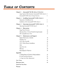
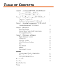
1
Installation/Operation/Service Manual
XenaLight™ Fiberoptic Illuminator
Model #FTIHL17521 (100-120V~)
Table of Contents
Rev A
To ensure safety, this operating manual should be read and understood in IM-005FTI
its entirety
before operating the XenaLight™ Fiberoptic Illuminator. It is essential to follow the
instructions contained herein with particular attention given to the warnings and
cautions.
SPECIFICATIONS
Product Classification ...................................................................................................... 1
Technical Specifications .................................................................................................. 2
Allowable Ambient Conditions ........................................................................................ 2
INSPECTION OF UNIT
Receiving/Handling .......................................................................................................... 3
System Inspection............................................................................................................ 3
SYMBOL EXPLANATION.......................................................................................................... 4
WARNING/CAUTION.................................................................................................................. 5
EQUIPMENT LAYOUT / FUNCTIONALITY
Front Panel ..................................................................................................................... 6
Back Panel ...................................................................................................................... 7
GENERAL OPERATION
Illuminator Operation ....................................................................................................... 8
Cleaning ............................................................................................................................. 8
LAMP INDICATOR / LAMP REPLACEMENT / PCB TIMER BOARD
Lamp Indicator .................................................................................................................. 9
Lamp Replacement.................................................................................................. 10-12
PCB Timer Board Replacement...................................................................................13
SERVICE / REPAIR / REPLACEMENT PARTS
Fuse Replacement .........................................................................................................14
Troubleshooting ..............................................................................................................14
Replacement Parts.........................................................................................................14
WARRANTY / NOTATIONS. ...................................................................................................15
WIRING SCHEMATIC ..............................................................................................................16
Page
1
Specifications
PRODUCT CLASSIFICATION:
The XenaLight™ Illuminator is designed for industrial and medical applications. It is
classified as Medical Equipment, UL2601-1CAN/CSA C22.2 No. 601.1 Continuous
Operation, Class I Equipment, Type BF. Not suitable for use near flammable anesthetic
mixtures, Ordinary Equipment, without protection against ingress of water.
The user must select a suitable fiberoptic connection device to assure proper and safe
function. Headlamps must be certified to assure safe and compliant use. Endoscopic
applications must include fiberoptic probes that are certified to IEC60601-2-18, which is
required for endoscopic equipment.
This equipment has been tested and found to comply with the limits for medical devices
in IEC-601-1-2: 1994. These limits are designed to provide reasonable protection
against harmful interference in a typical medical installation. This equipment generates,
uses and can radiate radio frequency energy and, if not installed and used in
accordance with the instructions, may cause harmful interference to other devices in the
vicinity. However, there is no guarantee that interference will not occur in a particular
installation. If this equipment does cause harmful interference to other devices, which
can be determined by turning the equipment off and on, the user is encouraged to try to
correct the interference by one or more of the following measures:
•
Reorient or relocate the receiving device. Increase the separation between the
equipment.
•
Connect the Equipment into an outlet on a circuit different from that to which the
other device(s) are connected.
•
Consult the manufacturer or field service technician for help.
Page
2
Specifications
TECHNICAL SPECIFICATIONS:
Input Specifications:
Electrical Rating:
Fuse Ratings:
Maximum Power Consumption:
100-120AC 50/60Hz
(2) 250V, 2.5A, Type F Quick Acting, 5x20mm
200 Watts
Physical Specifications:
Size:
Weight:
11.0” L x 10.5” W x 4.5” H
6.85 lbs
Illuminator Specifications:
Lamp Type:
Average Lamp Life:
Illuminating Aperture:
Dimming System:
Electrical Power Cord/Plug:
Mode of Operation:
Short Arc – HID, 120 Watt
Fiberoptics Technology Part #FTIHL17539
1,200 Hrs.
Up to 12.0mm
Manual iris
Hospital Grade
Continuous
ALLOWABLE AMBIENT CONDITIONS:
Operating Temperature:
Storage Temperature:
Operating Humidity:
0o C to 60o C
-18o C to 60o C
0% to 95% Relative Humidity, non-condensing
Page
3
Inspection of Unit
RECEIVING / HANDLING:
The XenaLight™ Illuminator is supplied in protective, non-sterile packaging.
Avoid placing the unit in a dusty or dirty environment. Dirt entering the air intake
may shorten the life of the unit.
Inspect shipping container for evidence of shipping damage, preferably in the
presence of the carrier. Noted damage should be reported to the carrier's agent.
Remove all packaging material from around the unit and carefully inspect for
damage.
SYSTEM INSPECTION:
The illuminator must be inspected before each use according to the procedure
below.
Should any irregularity or abnormality be found, do not use the
illuminator, contact Fiberoptics Technology, Inc., by Phone (800) 433-5248 or
Fax (860) 928-7664.
1.
Visually inspect the electrical powercord, receptacle, intensity control,
cable port to assure that there is no evidence of wear, damage or fraying.
2.
Be sure the fiberoptic cable connector being utilized is clean and dry
before plugging it into the cable port.
Page
4
Symbol Explanation
Continuous Operation, Class 1 Equipment, Type BF
Attention:
Read Instruction Manual for Warnings, Precautions and
Instructions for Use. Advises the user of a possibility of damage to the
equipment may occur.
Replace Fuse as Marked, Type F, 250V, 2.5A
Symbol on power switch indicates power is ON when pressed. Alternate
indication is a green LED switch light.
Symbol on power switch indicates power is OFF when pressed.
Protective Earth Ground
Symbol in electrical rating signified AC mains power
Advises the user of a hazard that could result in serious injury
Page
5
Warning/Caution
WARNING:
- The illuminator must not be used in the presence of flammable materials/gases
or solutions due to danger of possible explosion.
- One must not look directly at the lamp output. The light produces high intensity
visible and ultraviolet radiation that may burn the skin or eyes. The illuminator
must never be used in procedures requiring direct illumination of the eye, as
permanent eye damage may result.
- Grounding reliability is achieved only when connected to a "Hospital-Use" or
"Hospital-Grade" receptacle. Inspect electrical plug and cord routinely. Do not
use if damage is discovered.
- Due to the internal voltage of the power supply, a hazard exists for electrical
shock. Always disconnect the main power line before attempting any service or
replacement of lamps.
- Avoid bodily contact with the lamp and socket until they have sufficiently cooled.
Portions of the lamp can reach very high temperatures, which could cause
serious burns if touched while hot.
- Light emitting from the end of a fiberoptic cable can cause burns. Do not place
on protective drapes or the patient. Always allow illuminator to cool for a
minimum of 10 minutes before disconnecting a fiberoptic cable.
-
The XenaLight™ Lamp is under high pressure. Do not subject lamps to careless
handling or high mechanical forces. Lamp fracture may occur resulting in
possible personal injury. In the event of Lamp Failure, Notify Qualified Trained
Personnel immediately.
CAUTION:
- Do not block any air vents or louver. Adequate cooling is required for proper
operation of the unit.
- Do not operate unit if the fans are not operating properly.
- Fiberoptic cables must be rinsed free of soaking/disinfectant solution and dried
before plugging into the cable port. Use fiberoptic cables constructed with high
temperature epoxy.
Page
6
Equipment Layout
FRONT PANEL:
1.
POWER ON/OFF SWITCH
Turns Power On and Off.
2.
CABLE PORT
Provides proper connection for fiberoptic cable.
Cable port accessories
available for Acmi, Olympus, Storz, Pilling and Wolf type cables, as well as FTI’s
industrial port, which accepts active diameters up to 12mm (0.5”). Industrial port
ID is 0.718”.
3.
MANUAL INTENSITY CONTROL
Provides counterclockwise manual adjustment of light
Left Position – No Light
Right Position – Full Light
4.
LAMP INDICATOR
Provides personnel with lamp status (Refer to Page 9 for additional details).
Page
7
Equipment Layout
BACK PANEL:
1. COOLING EXHAUST WITH FINGER GUARD
2. SUPPLIER NAME AND ADDRESS
3. MODEL AND SERIAL NUMBER LABEL
Identifies specific illuminator. Use this number on all correspondence
about this illuminator.
4. INPUT POWER INFORMATION
Specifies input power required.
CAUTION: Always check model
number for correct voltage before connection. Damage may occur due to
application of incorrect voltage.
5. FUSE/FUSE HOLDER
Provides over current protection. Replace Fuse only as Marked, Type F,
250V, 2.5A.
6. POWER INPUT RECEPTACLE/CLIP:
Provides connection of power cord to illuminator. Clip holder provides
unwanted disconnection of power cord during use.
Page
8
General Operation
ILLUMINATOR OPERATION:
1. Do not drape objects over the illuminator. Verify that the side air intakes and rear
cooling exhaust louver are not blocked.
2. Connect to the proper power source using only "hospital grade" marked
3.
4.
5.
6.
7.
8.
powercord and receptacle.
WARNING: The power cord should never be
sharply bent, strained or crushed.
Insert a compatible, clean, dry, fiberoptic cable into the Cable Port. The user
must select a suitable fiberoptic connection device to assure proper and safe
function. Headlamps must be certified to assure safe and compliant use.
Endoscopic applications must include fiberoptic probes that are certified to
IEC60601-2-18, which is required for endoscopic equipment.
Industrial cables should have a protective optical rod in the input to minimize the
chance of damage to the fiber optic component.
Rotate the Intensity Control Knob counterclockwise to the OFF Position.
Turn Power Switch ON ..wait approximately 3 minutes for the lamp to reach full
output.
Adjust the intensity knob clockwise for the desired level of light
output/illumination.
When procedure is completed, turn the intensity control knob counterclockwise to
its lowest setting.
9. Switch the power switch to the (OFF) position.
WARNING: Allow the
illuminator to cool for a minimum of ten (10) minutes before disconnecting the
fiberoptic cable.
CLEANING (As Needed):
1. Before attempting any maintenance or cleaning of the system, be sure that the
system is OFF and disconnect the power source from both the illuminator and
the wall outlet. The illuminator housing must be kept free of dust and any
accumulation of dirt around the air intakes and cooling exhaust louver.
2. The exterior of the unit and power cord may be cleaned by wiping it with a
dampened (not dripping) cloth and a mild detergent. DO NOT IMMERSE.
WARNING: Be sure the power source and all connections are thoroughly dry
before plugging into wall outlet and illuminator.
Page
9
Lamp Indicator/Replacement
LAMP INDICATOR:
The lamp indicator provides three levels of CAUTION to end-user as follows:
1. 60 Second Red Flash - Lamp Warm-up
The indictor light will flash for the first 60 seconds when the unit is turned ON,
advising that the lamp is warming up. The indicator light will turn OFF when lamp
has reached optimum light output. Do not switch the light source ON and OFF
during warm up phase as this will dramatically shorten lamp life. Allow unit to sit
for 60 seconds before restarting lamp.
2. Continuous Red Flash – CAUTION - Spare Lamp Replacement
The indicator light will continuously flash at 1,200 hours and will not shut off when
unit is turned on. The continuous flash is advising that it is time to purchase a
new lamp.
3. Solid Red – CAUTION - New Lamp Required
The indicator light will illuminate solid red at 1,250 hours and will not shut off
when the unit is turned on. The solid red light is advising that the lamp is at the
end of its rated life and a new lamp needs to be installed by Qualified Trained
Personnel.
LAMP REPLACEMENT:
Since the unit is designed to accept a specific lamp design and configuration,
only use Fiberoptics Technology replacement lamp Part number FTIHL17539 or
FTIHL17540 (includes cooling cartridge).
Fiberoptics Technology, Inc., recommends that you always have a XenaLight™
lamp (Part number. FTIHL17539 or FTIHL17540 (includes cooling cartridge) in
stock to be replaced when the lamp reaches 1,200 hours of operation to insure
the user maximum reliability. Operation of the lamp beyond 1,200 hours may
result in lamp failure. It is recommended that the lamp be replaced before
illuminator has 1,250 hours. The PCB Timer Board (LT101) calculates the hours
of lamp operation and must be changed when replacing the lamp. Please review
page 13 for additional instructions.
WARNING:
Use only Fiberoptics Technology Lamp FTIHL17539 or
FTIHL17540 (includes cooling cartridge). Lamps are under high pressure and
must be handled with care. Safety glasses or face shield should be worn. For
optimum performance, avoid handling the bulb or reflector. Fingerprints or other
contaminates on the glass may result in performance degradation.
Only
Qualified Personnel that have appropriate training should change the lamp
cartridge. If no qualified personnel are available contact Fiberoptics Technology,
Inc. directly for lamp replacement.
Page
10
Lamp Replacement
STEP 1:
a) Power Illuminator OFF.
WARNING: Allow illuminator to cool for a minimum
of 30 minutes, if unit has been running.
b) Disconnect power cord from Illuminator. Remove top cover by turning the
illuminator on its side and remove four screws.
c) Remove two (2) Cap screws on Lamp Cover Door as indicated below.
1
1
1
Page
11
Lamp Replacement
STEP 2:
a) Disconnect Lamp Wire from Power Supply
b) Remove Two (2) Lock Nuts from Chassis
c) Remove Lamp Cartridge from Unit
2
3
1
Page
12
Lamp Replacement
STEP 3:
a) Remove four (4) cap screws from retaining plate.
b) Remove retaining plate from cartridge assembly and replace with new
XenaLight™ lamp (Fiberoptics Technology FTIHL17539 or FTIHL17540
(includes cooling cartridge).
2
1
STEP 4: REINSTALL NEW LAMP
a) Place lamp into cartridge with retaining plate and four (4) cap screws. Place
cartridge back into chassis with two (2) lock nuts, and connect lamp wires to
power supply.
b) Place lamp cover door in place with four (4) cap screws and properly attach top
cover to chassis with four (4) screws.
Page
13
PCB Timer Board
Once you have replaced the lamp, please proceed with the following:
STEP1:
a) Disconnect Wires from PCB Timer Board (LT101) that lead to Power Supply
b) Disconnect Wires from PCB Timer Board (LT101) that lead to LED Indicator Light
c) Remove Three (3) Screws from Board
d) Remove PCB Timer Board from Unit
STEP2:
a) Install new PCB Timer Board into Unit
b) Place Three (3) Screws into Mounting Holes
c) Attach Wires from LED Indicator Light into PCB Timer Board (Positive Symbol
noted on Board and Wire)
d) Attach Wires from Power Supply to PCB Timer Board (Positive Symbol noted on
Board and Wire)
2
4
3
1
Page
14
Service/Repair/Replacement Parts
FUSE REPLACEMENT:
WARNING: Fuse replacement must be completed with power cord disconnected.
Two (2) fuses are present in fuse holder. Use the same type, same rated fuse as
marked and specified to avoid risk of fire hazard. No Special Tool Required.
TROUBLESHOOTING:
SYMPTOM
PROBABLE CAUSE
Fan not Running
Check Main Power Connection
Cover not Properly Closed and Tightened
Lamp Does Not Ignite
Check Main Power Connection
Cover not Properly Closed and Tightened
Check Lamp Indicator to verify if lamp is near 1,200 hours
Lamp Improperly Installed (Refer to Lamp Replacement
Procedure – Page 10-12)
Lamp has Low Output
Check Lamp Indicator to verify if lamp is near 1,200 hours
Check Intensity Control Knob for proper functioning
Check Fiberoptic Cable for Broken Fibers/Transmission
All other repairs and maintenance not mentioned in this section or manual are not user
serviceable and should be referred directly to Fiberoptics Technology, Inc. for service
and/or repair. When requesting information concerning the systems, always furnish
serial and model numbers identified on the back panel of the illuminator.
REPLACEMENT PARTS:
Description
XenaLight Lamp •
XenaLight Lamp w/Cartridge •
One
One
Order Number
FTIHL17539
FTIHL17540
To obtain additional replacement parts or other fiberoptic accessories, please write,
phone or fax:
Fiberoptics Technology, Inc.
1 Quassett Road
Pomfret, CT 06258
Phone: (800) 433-5248
Fax: (860) 928-7664
Page
15
Warranty/Notations
WARRANTY:
Fiberoptics Technology, Inc., Inc. warrants the XenaLight™ Illuminator when new, to be
free of defects in material and workmanship and to perform in accordance with
manufacturer’s specifications when subject to normal use and service for a period of
one year from date of purchase from Fiberoptics Technology, Inc. or an authorized
agent. Fiberoptics Technology, Inc. will either repair or replace any components found
to be defective or at variance from manufacturer’s specification within this time at no
cost to the customer. It shall be the purchaser’s responsibility to return the product to
the authorized distributor, agent, or service representative.
This warranty does not cover the product of breakage or failure due to tampering,
misuse, neglect, accidents, improper installation, modification, shipping, or to improper
maintenance, service and cleaning procedures. This warranty is also void if the product
is not used in accordance with manufacturer’s recommendations or if required service
by other than Fiberoptics Technology, Inc. or an authorized agent. Purchase date
determines warranty requirements. No other express or implied warranty is given.
DISPOSAL:
When life of this product or lamp has ended, dispose of it reliably and properly in a
dedicated container and not with general waste. Fiberoptics Technology, Inc. cannot
advise lamp users as to general or specific disposal regulations for federal,
state/provincial, and/or local municipalities.
It is the responsibility of the waste
generator to ensure proper classification and disposal of waste products.
NOTATIONS:
The information contained in this manual is subject to change without notice.
Fiberoptics Technology, Inc. makes no warranty of any kind with regard to this material,
including, but not limited to, the implied warranties or merchantability and fitness for a
particular purpose. Fiberoptics Technology, Inc. shall not be liable for errors contained
herein or for incidental consequential damages in connection with the furnishing,
performance, or use of this material.
ACMI, Olympus, Pilling, Storz and Wolf are trade names for each respective company.
Page
16
Wiring Schematic