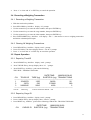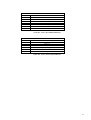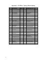
1
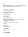
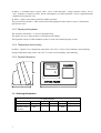
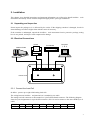
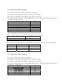
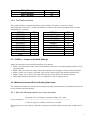
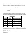
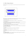
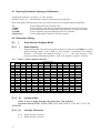
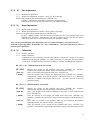
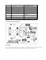
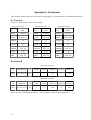
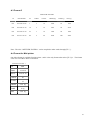
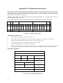
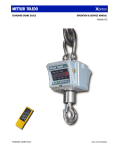
8142PRO + (PR08) Industrial Terminal Service Manual 1 1. Introduction This manual describes the 8142Pro+ dual display scale terminal (PRGN-XXX8), which is tailor designed to meet the vehicle and floor scale needs. Installation and service procedure should be performed only by authorized personnel. 1.1 8142Pro+ Features • • • • • • • • • • • • • • • • • • • • • • • • • • • Two 7 digits numeric vacuum fluorescent displays 24 position keypad Input for up to eight 350Ω analog load cells The selectable increments from 1000 to 50,000 A/D internal Resolution: 1,000,000 Display update rate: 10 updates each second Pushbutton and keyboard tare Tare interlock function The expanded weight display Tare and clear tare automatically Automatic zero maintenance Motion detection and indication Center of zero indication Real time clock by battery back-up 500 truck ID/Tare record (8 digits truck ID) 99 cargo ID subtotal (2 digits cargo ID) 99 client ID subtotal (2 digits client ID) 1000 transactions record ( the information include CN, time and date, truck ID, cargo ID, client ID, gross, tare and net ) Accumulators by truck ID, cargo ID or client ID Daily report printout 4 printout formats 2 serial communication interface (continuous output port and host port) 1 parallel centronics interface Host interface High accurate delta-sigma A/D converter TraxDSPTM vibration rejection SMT technology 1.2 8142Pro+ Specifications 1.2.1 Analog Load Cell • • • Excitation Voltage: +10VDC, power up to eight 350Ω analog load cells Span range: 3 ~ 32mV Zero range: 0 ~ 25mV 1.2.2 Power Requirements 1 8142Pro+ is available in four versions. 100V , 120V , 220V and 240V , voltage variation is from –15% to +10% , frequency is from 49 to 63Hz . Power consumption is 12 Watts maximum . Power is applied through a modular power plug line cord. 8142Pro+ requires a true earth ground for reliable operation. The power line for 8142Pro+ must not be shared with equipment such as motors, relays, or heaters that generate line noise. 1.2.3 Display and Keyboard The enclosure of 8142Pro+ is cast zinc-aluminum alloy. The display are two 7 digits numeric vacuum fluorescent display. The keyboard consists of a flat membrane switch covered with a domed polyster overlay. 1.2.4 Temperature and Humidity 8142Pro+ operates over a temperature range from -10 to 40 °C at 10% to 95% humidity, noncondensing. Storage temperature range is from -40 to 60 °C at 10% to 95% humidity, noncondensing. 1.2.5 Physical Dimension 8142PRO 1000 204 0 METTLER TOLEDO 168 324 1.3 Ordering Information 8142Pro+ MODEL CONFIGURATION ex: PRGN-0038-023 PRGN X X X X MODEL PCB type Reserved Market DISPLAY 1 - Analog L/C 0 3- Export 7 - Single PR - 8142Pro+ 8 – Dual G-General housing 2 - HAP N - Numeric 2 XXX Country 023 - CHINA 2. Installation This chapter gives detailed instructions and important information you will need to install 8142Pro+ scale instrument successfully. Please read this chapter throughly before you begin installation. 2.1 Unpacking and Inspection Please inspect the package as it is delivered by the carrier. If the shipping container is damaged, check for internal damage and file a freight claim with the carrier if necessary. If the container is undamaged, unpack the 8142Pro+ scale instrument from its protective package, noting how it was packed, and inspect each component for damage. 2.2 Electrical Connections Printer Platform Scale 1 1500 500 Computer 计算机 Scoreboard 1000 kg 1000 ScaleWin PQ30 IBM 1 LOAD CELL PARALLEL 1 1 1 COM1 COM2 Power Cord 8142PRO PR8 Terminal 2.2.1 Connect the Load Cell 8142Pro+ powers up to eight 350Ω analog load cells. The wiring between 8142Pro+ and junction box is standard 6-wire cable The analog load cell connector to the terminal is a 9 pin D-SUB female connector. The following diagram shows the pins assignments for 9 pin D-SUB connector. (Pin 9 is used to connect to the outer shield layer of cable) SIGNAL PIN +EXC 1 +SEN 2 SHLD 3 -SEN 4 -EXC 5 +SIG 7 -SIG 8 GND 9 3 2.2.2 Serial Port COM1 Connection The serial port COM1 consist of RS-232 and 20 mA current loop. The maximum recommended cable length for RS-232 interface is 50 feet. The maximum recommended cable length for 20 mA interface is 1000 feet. The serial port COM1 connector is a 25 pin D-SUB female connector. The following diagram shows the pins assignments for COM1 connector. SIGNAL PIN SHIELD GROUND TXD (RS-232) RXD (RS-232) SIGNAL GROUND CLRX+ CLTX+ CLRX- 1 2 3 7, 19, 22, 23 8, 16 9 10, 18 Note: The transmitter of 20 mA current loop is active, the receiver is passive. Below is the pin assignment of 8142Pro+ 8 to the Mettler-Toledo scoreboard . COM1 at 8142Pro+ 7 Mettler-Toledo Scoreboard 9 7 1 2 CLRX+ CLRX- If you want to connect your 8142Pro+ 8 to the computer , please refer to the below sheet for pin assignment . COM1 Computer ( 9 pin ) Computer ( 25 pin ) 2 2 3 3 3 2 7 5 7 2.2.3 Serial Port COM2 Connection The serial port COM2 consist of RS-232 and RS-422. The maximum recommended cable length for RS-232 interface is 50 feet. The maximum recommended cable length for RS-422 interface is 2000 feet. The serial port COM2 connector is a 25 pin D-SUB female connector. The following diagram shows the pins assignments for COM2 connector. SIGNAL SHIELD GROUND TXD (RS-232) RXD (RS-232) SIGNAL GROUND TXD+ (RS-422) 4 PIN 1 2 3 7 11 TXD- (RS-422) RXD+ (RS-422) RXD- (RS-422) 12 13 24 2.2.4 The Parallel Interface The parallel interface is standard Centronics printer interface. It is used to connect to a printer. The parallel port connector is a 25 pin D-SUB female connector. The following diagram shows the pins assignments for connector. SIGNAL STRORE DATA BIT0 DATA BIT1 DATA BIT2 DATA BIT3 DATA BIT4 DATA BIT5 DATA BIT6 DATA BIT7 ACK- PIN 1 2 3 4 5 6 7 8 9 10 SIGNAL BUSY PAPER EMPTY SELECT AUTO FEED ERRORINITSELECTSIGNAL GND PIN 11 12 13 14 15 16 17 18 ~ 25 2.3 8142Pro+ Jumper and Switch Settings Jumper and switches on the main PCB should be set as follows: • • • • • K1-1 is the setup enable switch. This switch should be ON to access all setup parametersand be OFF in operating mode . K1-2 is selection switch for comma. This switch should be ON to display comma (not decimal point). K1-3 is used to access factory test mode. This switch is always OFF in the normal operation mode. K1-4 is used to access factory test mode. This switch is always OFF in the normal operation. W1 jumper should be removed for 3 mV/V, installed for 2 mV/V analog load cell. 2.4 Minimum Increment Size for Analog Scale Input The minimum increment size selection for an analog scale input is determined by calculating the microvolts per increment for the desired build. 2.4.1 Solve the following equation for µV per increment. Increment Size x cell output x excitation voltage (15) x 1000 µV per Increment = --------------------------------------------------------------------------------Load Cell Capacity x Number of Cells or Level Ratio The increment size, scale capacity, and load cell capacity must all be measured in the same weight units, lb or kg. 5 Load cell output is rated in mV/V (millivolts per volt of excitation), marked on load cell data tag. Mettler Toledo load cells are typically 2 mV/V. Other load cells can range from 1 mV/V to 4.5 mV/V. The load cell capacity is the rated capacity marked on load cell data tag. The number of cells is the total number of load cells in the system , for the electronic –mechanical scale , the level ratio is the total level ratiop in the system . 2.4.2 Calculate the total number of increments by dividing the calibrated capacity by the increment size. Calibrated Capacity # Increments = ---------------------------Increment Size 2.4.3 Microvolt build table Use the following microvolt build table to determine if the µV per increment calculated in step 1 is within the range allowed for the total number of increments calculated in step 2. These parameters have demonstrated stable builds but smaller minimum µV per increment and larger total number of increments are possible. Total Number of Increment 1,000 2,000 2,500 3,000 4,000 5,000 6,000 8,000 10,000 20,000 50,000 Microvolt Build Table Minimum µV per Maximum mV per Increment Increment 2 mV/V 3 mV/V 3.0 26.0 38.0 1.5 13.0 19.0 1.2 10.4 15.2 1.0 8.7 12.7 0.75 6.5 9.5 0.6 5.2 7.6 0.5 4.4 6.4 0.375 3.3 4.8 0.3 2.6 3.8 0.15 1.3 1.9 0.1 0.52 0.76 Note: 8142Pro+ should never be programmed for least than 0.5 µV per increment when used with single load cell applications and never less than 0.1 µV per increment when used with multiple load cell applications. 8142Pro+ cannot be calibrated for builds that exceed the maximum µV per increment listed in the microvolt build rate. 3. 8142Pro+ Operations This chapter provides information that an operator will need to become fimiliar with the terminal and to perform its functions. 6 3.1 8142Pro+ Display and Keyboard 8142Pro+ dual display version has two displays where scale data and operational message are presented. These are pictured below: Kg 0 ~ Tare Time G Net Date Accum. CN Truck ID Cargo ID Client ID Report The two displays are same. The display is a numeric display. This area can display up to seven numbers each with a decimal point, comma, and annunciators. The annuniciators are: • Center-of-zero (→ o ← ) The center-of-zero annunciator indicates that the scale is within ± ¼ increment of gross zero. • Scale in-motion ( ~ ) The scale instability annunciator indicates that the scale is in motion. The annuniciator will turn off when the scale is stable. The motion sensitivity of motion detection is adjustable in setup. • Weighing mode ( Gross or NET) The 8142Pro+ will be in Net mode when a tare is active. Tare can be entered as a Preset tare value or tare may be automatically acquired when the operator presses the TARE key. • Consecutive Number ( CN ) The consecutive number annunciator indicates CN has been recalled and displayed. You can exit the recall mode of CN by pressing EXIT key. • Truck ID The truck ID annunciator indicates that you are entering a truck identification. • TARE The tare annunciator indicates a pushbutton tare or keyboard tare is active. • TIME/DATE The time annunciator indicates TIME has been displayed. The date annunciator indicates DATE has been displayed. • Accumulator (Accum.) The accumulator annunciator indicates accumulation has been recalled and displayed. You can exit the recall mode of accumulation by pressing EXIT key. 7 • Cargo ID The cargo ID annunciator indicates that you are entering a cargo identification. • Client ID The client ID annunciator indicates that you are entering a client identification. • Report The report annunciator indicates that the scale is in report mode. 8142Pro+ dual display version is equipped with a 24-key keypad as seen below: The keypad consists of numeric keys 0 through 9 and fourteen function keys. The keys perform the following functions: • • • • • • • • • • • • • 8 NUMERIC keys are used to input numbers. ZERO zeros the scale. The ZERO key also functions as backspace when entering data from the keypad. TARE performs a pushbutton tare or keyboard tare if enabled in setup. CLEAR clears a tare value and returns the scale to gross mode. The CLEAR key also functions as delete when entering data from the keypad. Truck ID acknowledges a prompt and accepts data as truck ID entered from the keypad. Cargo ID acknowledges a prompt and accepts data as cargo ID entered from the keypad. Client ID acknowledges a prompt and accepts data as client ID entered from the keypad. CN key is used to recall consecutive number. RECALL is used to recall consecutive number or accumulations. TIME/DATE key is used to enter or recall the clock and the date. REPORT can generate and print truck-related, cargo-related and client-related reports. RECORD key is used to store a weighing transaction. ENTER/PRINT acknowledges a prompt and accepts data entered from the keypad. It also initiates a demand print output. 3.2 The Basic Operator Functions 3.2.1 Power-up Sequence 8142Pro+ goes through a series of self- tests when it is turned on. These self- tests confirm normal operation. The power-up sequence is as follows: 1. 2. 3. 4. All segments of the display are lit. This verifies operation of all segments. 8142Pro+ displays the software part number “131106” and revision number “L x.x”. 8142Pro+ performs internal power-up tests, verifies internal memory, Finally, if enabled, 8142Pro+ power-up timer will start. Before the unit advances to normal operating mode, it display all dashes. Pressing EXIT key, it will returns to normal operating mode. 3.2.2 Zero the Scale If pushbutton zero is enabled, you can press ZERO key to establish a new zero center of reference for the scale when in the gross mode. In motion or residual weight on scale greater than pushbutton zero range will cancel this operation. 3.2.3 Tare Operation 8142Pro+ supports pushbutton tare, preset (keyboard) tare and clear tare operations. • Pushbutton Tare In gross mode, place the container to be weighed on the platform and press the TARE key, The 8142Pro+ reads 0.0 with the NET annunciator illuminated. • Preset (keyboard) Tare Preset tare, sometimes called keyboard tare, compensates for a known tare weight on the scale. Preset tare is used when the net weight of contents in a filled container must be determined and the tare weight is known. 1. Place the load on the platform. The display shows the gross weight of the load. Be sure you know the weight of the portion to be compensated for by preset tare. 2. Use the numeric keys to enter the known tare weight, then press TARE key. The net weight of the load is displayed with an annunciator indicating NET. • Clear Tare Clear tare by pressing CLEAR key. 8142Pro+ returns to gross mode and displays the gross weight on the platform. 3.2.4 Print Operation In normal operating mode, demand printing is initiated when an operator presses the ENTER/PRINT key. During demand print output, “ P--- “ will be displayed. 3.3 Truck ID/Tare Operation 3.3.1 Entering a Truck ID/Tare • Entering an unknown tare weight 9 1. Place a load to be tared on the platform. The upper display shows the gross weight of the load. 2. Press TRUCK ID key, 8142Pro+ display “id 3. Use the numeric keys to enter the truck number, then press TARE key. The truck number and the related tare will be stored. • “prompt. Entering a known tare weight 1. Press TRUCK ID key, 8142Pro+ display “id “ prompt. 2. Use the numeric keys to enter the truck number, then press ENTER key. 8142Pro+ accept the truck ID, the top display show the entered TRUCK ID, the lower display show the stored tare corresponding to the stored TRUCK ID. 3. Use the numeric keys to enter the tare value, then press TARE key. The truck number and tare will be stored. 3.3.2 Recall a Truck ID/Tare 1. Press TRUCK ID key, 8142Pro+ display “id “ prompt. 2. Use the numeric keys to enter the truck number, then press ENTER key. 8142Pro+ accept the truck ID, the top display show the entered TRUCK ID, the lower display show the stored tare corresponding to the stored TRUCK ID. 3. Press TARE key, 8142 recall the tare value corresponding to the above entered TRUCK ID, then return to net operating mode. 3.3.3 Display a Temporary Truck ID/Tare 1. Press TRUCK ID key, 8142Pro+ display “id “ prompt. 2. Use the numeric keys to enter the truck number, then press ENTER key. 8142Pro+ accept the truck ID, the top display show the entered TRUCK ID, the lower display show the stored tare corresponding to the stored TRUCK ID. 3. Press ENTER key, the 8142Pro+ will return to the normal operating mode. 3.3.4 Clear Truck ID/Tare • Clear All Truck ID/Tare 1. Press TRUCK ID key, 8142Pro+ display “id “ prompt. 2. Press CLEAR key, the lower display show “Clr ALL” prompt. 3. Press “1” to clear and “0” or EXIT key to cancel the operation. • Clear a Truck ID/Tare 1. Press TRUCK ID key, 8142Pro+ display “id “ prompt. 2. Use the numeric keys to enter the truck number, then press ENTER key. 8142Pro+ accept the truck ID, the top display show the entered TRUCK ID, the lower display show the stored tare corresponding to the stored TRUCK ID. 3. 10 Press CLEAR key, the lower display show “Clr it” prompt. 4. Press “1” to clear and “0” or EXIT key to cancel the operation. 3.4 Recording a Weighing Transaction 3.4.1 Recording a Weighing Transaction 1. With the truck on the platform 2. Press RECORD key, 8142Pro+ display “id ” prompt. 3. Use the numeric keys to enter the truck number, then press ENTER key. 4. Use the numeric keys to enter the cargo number, then press ENTER key. 5. Use the numeric keys to enter the client number, then press ENTER key. 6. Press ENTER/PRINT key, 8142Pro+ will display “ PS---” , that means to store a weighing transaction and initiate a demand print output. 3.4.2 Clearing All Weighing Transactions 1. Press REPORT key, 8142Pro+ display “total “ prompt. 2. Press CLEAR key, the lower display showes “Clr ALL” prompt. 3. Press “1” to clear and “0” or EXIT key to cancel the operation. 3.5 Report Operation 3.5.1 Report by Truck ID 1. Press REPORT key, 8142Pro+ display “total “ prompt. 2. Press TRUCK ID key, the top display show “id 3. Press PRINT key, 8142Pro+ print out the following ” prompt. TRUCK ID - TRANSACTION table. DATE/TIME: 1999/02/26 08:26 CN TRUCK ID TARE (kg) SUBTOTAL (kg) TRANSACTIONS -----------------------------------------------------------------------------------------------1 12345678 1250 24600 26 2 13579 530 578960 580 3 24680245 2680 4600 2 -----------------------------------------------------------------------------------------------TOTAL: 608160 kg TOTAL TRANSACTIONS: 608 3.5.2 Report by Cargo ID 1. Press REPORT key, 8142Pro+ display “total “ prompt. 2. Press CARGO ID key, the top display show “CArGo ” prompt. 3. Press PRINT key, 8142Pro+ print out the following CARGO ID - TRANSACTION table. CN CARGO ID DATE/TIME: SUBTOTAL (kg) 1999/02/26 08:28 TRANSACTIONS 11 -----------------------------------------------------------------------------------1 12 24000 18 2 15 258580 176 3 22 3240 2 ------------------------------------------------------------------------------------TOTAL: 285820 kg TOTAL TRANSACTIONS: 196 3.5.3 Report by Client ID 1. Press REPORT key, 8142Pro+ display “total “ prompt. 2. Press CLIENT ID key, the top display show “CLiEnt ” prompt. 3. Press PRINT key, 8142Pro+ print out the following CLIENT ID - TRANSACTION table. DATE/TIME: 1999/02/26 08:28 CN CLIENT ID SUBTOTAL (kg) TRANSACTIONS -----------------------------------------------------------------------------------1 12 24000 18 2 15 258580 176 3 22 3240 2 ------------------------------------------------------------------------------------TOTAL: 285820kg TOTAL TRANSACTIONS: 196 3.5.4 Report by Date 1. 2. 3. 4. Press REPORT key, 8142Pro+ display “total “ prompt. Press ENTER key, the lower display show “dAtE ” prompt. Use the numeric key to enter 4-digits date (month and day). Press PRINT key, 8142Pro+ print out the following TRANSACTION table. DATE: 1999/02/26 CN TIME TRUCK ID CARGO ID CLIENT ID GROSS(kg) TARE(kg) NET(kg) -----------------------------------------------------------------------------------------------------1 08:10 12345678 03 15 3250 1200 2050 2 09:20 24680 16 01 24360 7650 16710 3 09:25 2468310 08 20 5800 850 5950 -----------------------------------------------------------------------------------------------------Accumulated Gross: 33410 kg Accumulated Net: 24710 kg 3.6 Recall Operation 3.6.1 Recall CN (Consecutive Number) 1. Press RECALL key, 8142Pro+ display “rECALL ” prompt. 2. Press CN key, 8142Pro+ display the next CN “Cn 0021”. 3. Press any key, 8142Pro+ returns to normal operating mode. Note : The CN is automatic generated by 8142Pro+ , and you can’t change that by yourself . The CN will come back to1 after the transaction are all cleared . 12 3.6.2 Recall Total 1. Press RECALL key, 8142Pro+ display “rECALL “ prompt. 2. Press REPORT key, 8142Pro+ display the current accumulated value. The top display shows the most significant 3 digits, the lower display show the least significant 7digits. 3. Press any key, 8142Pro+ returns to normal operating mode. 3.6.3 Recall Subtotal by Truck ID 1. Press RECALL key, 8142Pro+ display “rECALL “ prompt. 2. Press TRUCK ID key, 8142Pro+ display “id 3. Use the numeric key to enter truck ID, then press ENTER key. 8142Pro+ display the current truck ID-related subtotal. 4. Press ENTER key, 8142Pro+ display the current truck ID-related accumulated number (transactions). 5. Press any key, 8142Pro+ returns to normal operating mode. “ prompt. 3.6.4 Recall Subtotal by Cargo ID 1. Press RECALL key, 8142Pro+ display “rECALL “ prompt. 2. Press CARGO ID key, 8142Pro+ display “cArGo “ prompt. 3. Use the numeric key to enter cargo ID, then press ENTER key. 8142Pro+ display the current cargo ID- related subtotal. 4. Press ENTER key, 8142Pro+ display the current cargo ID-related accumulated number (transactions). 5. Press any key, 8142Pro+ returns to normal operating mode. 3.6.5 Recall Subtotal by Client ID 1. Press RECALL key, 8142Pro+ display “rECALL “ prompt. 2. Press CLIENT ID key, 8142Pro+ display “cLiEnt “ prompt. 3. Use the numeric key to enter client ID, then press ENTER key. 8142Pro+ display the current client ID-related subtotal. 4. Press ENTER key, 8142Pro+ display the current client ID-related accumulated number (transactions). 5. Press any key, 8142Pro+ returns to normal operating mode. 4. Programming and Calibration This chapter discusses 8142Pro+ ’s parameters setting and calibration. Please read this chapter thoroughly before you begin programming and calibration. 13 4.1 Entering Parameters Setting and Calibration Openning the enclosure, set the K1-1 to “ON” position. 8142Pro+ shows “F1 ” automatically to express it has been in the setup mode. In the setup mode, The following several keys can be used to access programming and calibration. “0” “ZERO” “EXIT” “ENTER” Numeric Keys Used to display the next selectable value. Used to back up in the current program block and return to the previous step. Used to exit back to the first step of the current block or of the previous block . Used to complete a response and display the next parameter. Used to input numeric entries such as scale capacity. 4.2 Parameters Setting [F1 ] [F1.1 Scale Interface Program Block ] Scale Capacity Entering the desired scale capacity using the numeric keys, then press “ENTER” key. In the normal operating mode, if the weight on scale exceeds 5 increments over capacity, 8142Pro+ will display over-capacity message “┌────┐”. The scale capacity is only entered according to the following Table 1, other scale capacities can not be accepted. 4.2.1 Table 1: Scale capacity selection Inc. 0.001 0.002 0.005 0.01 0.02 0.05 0.1 0.2 0.5 1 2 5 10 20 50 1000d 1 2 5 10 20 50 100 200 500 1000 2000 5000 10000 20000 50000 [F1.2 2000d 2 4 10 20 40 100 200 400 1000 2000 4000 10000 20000 40000 100000 5] 2500d 5 25 50 125 250 500 1250 2500 5000 12500 25000 50000 125000 3000d 3 6 15 30 60 150 300 600 1500 3000 6000 15000 30000 60000 150000 4000d 4 8 20 40 80 200 400 800 2000 4000 8000 20000 40000 80000 200000 Total Increments 5000d 6000d 5 6 10 12 25 30 50 60 100 120 250 300 500 600 1000 1200 2500 3000 5000 6000 10000 12000 25000 30000 50000 60000 100000 120000 250000 300000 8000d 8 16 40 80 160 400 800 1600 4000 8000 16000 40000 80000 160000 400000 10000d 10 20 50 100 200 500 1000 2000 5000 10000 20000 50000 100000 200000 500000 20000d 20 25 100 200 400 1000 2000 4000 10000 20000 40000 100000 200000 400000 - 50000d 50 100 250 500 1000 2500 5000 10000 25000 50000 100000 250000 500000 - Increment Size Press “0” key to toggle through valid selections. The available increment size are 0.001, 0.002, 0.005, 0.01, 0.02, 0.05, 0.1, 0.2, 0.5, 1, 2, 5, 10, 20 and 50. [F1.3 X] Linearity Correction X = 0 Disable linearity correction X = 1 Enable linearity correction 14 [F1.4 X] Zero Adjustment X = 0 Disable zero adjustment X = 1 Enable zero adjustment, 8142Pro+ shows [E SCL] prompt. Remove any weight on the platform and press “ENTER” key. 8142Pro+ automatically proceeds to capture zero and the display count down from 15 to 0, then advances to the next parameter setting. [F1.5 X] Span Adjustment X = 0 Disable span adjustment X = 1 Enable span adjustment, 8142Pro+ shows [Add Ld] prompt. Place a test weight on the platform and press “ENTER” key. At the [ 00000] prompt, enter the amount of weight placed on the platform, then press “ENTER” key, 8142Pro+ automatically proceeds to capture the new span and the display count down from 15 to 0, then advances to the next parameter setting. Note : Before performing the span adjustment , the test weights should have been placed on the platform in operating mode , then put K1-1 at “ ON ” and 8142Pro+ enter into setup mode in order to perform span adjustment . [F1.6 X] Calibration X = 0 Disable calibration X = 1 Enable calibration. Calibration involves emptying the scale then placing a known test weight on an empty platform and allowing the 8142Pro+ to capture values for zero and span. You can calibrate a scale with or without linearity correction. 8142Pro+ prompts you through the calibration. [F1.3 = 0] Without Linearity Correction [E SCL] [Add Ld] [ 00000] Remove any weight on the platform, then press “ENTER” key, 8142Pro+ automatically capture zero and the display count down from 15 to 0. Place a test weight on the platform, then press “ENTER” key. Enter the amount of test weight you added then press “ENTER” key. 8142Pro+ automatically capture span and the display count down from 15 to 0. When the calibration completed, the display shows [CAL d], then continue to the next parameter setting. [F1.3 = 1 ] With Linearity Correction [E SCL] [Add Hi] [ 00000] [Add Lo] [ 00000] Remove any weight on the platform, then press “ENTER” key, 8142Pro+ automatically capture zero and the display count down from 15 to 0. Place a test weight on the platform equaling at least 60% of scale capacity, then press “ENTER” key. Enter the amount of test weight you added above then press “ENTER” key. 8142Pro+ automatically capture hi-scale point and the display count down from 15 to 0. Place some test weight on the platform, make the test weight on the platform equaling between 30% and 60% of the scale capacity. Enter the amount of test weight on the platform then press “ENTER” key. 8142Pro+ automatically capture mid-scale and the display count down from 15 to 0. 15 When the calibration completed, the display shows [CAL d], then continue to the next parameter setting. [F1.7 X] The Expanded Weight Display X = 0 Normal weight display mode X = 1 Weight displayed in minors , 1 display increment = 10 minors [F2 ] [F2.1 X] X=0 X=1 X=2 X=3 [F2.2 ] Application Environment Program Block The Power-up Time Delay Disable the power-up time delay The power-up time delay is 10 minutes The power-up time delay is 20 minutes The power-up time delay is 30 minutes Zero Operation Select “ENTER” key to enter zero operation or select “0” key to exit without zero operation. [F2.2.1 X] Power-up Zero Operation X = 0 Power-up zero disabled X = 1 Enable power-up zero within ±2% FS range X = 2 Enable power-up zero within ±20% FS range [F2.2.2 X] Pushbutton Zero Operation X=0 X=1 X=2 X=3 Pushbutton zero disabled Enable pushbutton zero within ±2% FS range Enable pushbutton zero within ±3% FS range Enable pushbutton zero within ±20% FS range [F2.2.3 X] Auto Zero Maintenance X=0 X=1 X=2 X=3 [F2.3 ] AZM disabled AZM within ±0.5d window AZM within ±1.0d window AZM within ±3.0d window Tare Operation Select “ENTER” key to enter tare operation or select “0” key to skip without tare operation. [F2.3.1 X] Enable Tare X = 0 Tare disabled X = 1 Tare enabled [F2.3.2 X] 16 Tare Interlock X = 0 Tare interlock disabled X = 1 Tare interlock enabled [F2.3.3 X] Auto Tare X = 0 Auto tare disabled X = 1 Auto tare enabled , if the weight is more than 5d and in stable condition , 8142Pro+ will auto-tare . [F2.3.4 X] Auto Clear Tare X = 0 Auto clear tare disabled X = 1 Auto clear tare enabled , if the scale is in gross zero , and 8142Pro+ will auto clear tare . [F2.3.5 XX] Keyboard Tare Enter the range of the keyboard tare XX is the percent of FS . XX =0 means keyboard tare disabled [F2.4 X] Motion Sensitivity X = 0 Motion detector disabled X = 1 ±1.0d motion sensitivity X = 2 ±3.0d motion sensitivity [F2.5 2.0] Digital Filter X.X is the number data entry for the low pass filter corner frequency (0.5 ~ 9.9). [F2.5.1 X] Noise Filter Enable/Disable X = 0 Disable noise filter X = 1 Enable noise filter [F3 ] COM1 Program Block [F3.1 ] Baud Rate [ XXXX] XXXX = a selection list of 300, 1200, 2400, 4800 or 9600 baud rate. [F3.2 X] Data Bits X = 7 7 data bits X = 8 8 data bits [F3.3 X] Parity X = 0 No parity X = 1 Odd parity X = 2 Even parity 17 [F3.4 X] Checksum X = 0 Disable checksum X = 1 Enable checksum [F3.5 X] Serial Data Out X = 0 None X = 1 Continuous mode X = 2 Demand mode , single line gross , tare , net weights [F3.6 X] Discrete ASCII input X = 0 Disable X = 1 Enable discrete ACSII demand input Z = Zero T = Tare C = Clear P = Print [F4 ] COM2 Program Block [F4.1 ] Baud Rate [ XXXX] XXXX = a selection list of 300, 1200, 2400, 4800 or 9600 baud rate. [F4.2 X] Data Bits X = 7 7 data bits X = 8 8 data bits [F4.3 X] Parity X = 0 No parity X = 1 Odd parity X = 2 Even parity [F4.5 X] X=0 X=1 X=2 X=3 [F4.5.1 X] Serail data out None Continuous mode , and advance to F4.5.1 Host mode , and advance to F4.5.2 Reseverd Checksum X = 0 Disable checksum if continuous output mode X = 1 Enable checksum if continuous output mode 18 [F4.5.2 XX] The Address of Host XX is the number data entry for the address of 8142Pro+ 8 (01 ~ 15). [F5 ] [F5.1 X] Centronics Interface Program Block Printer Selection X = 0 80 column printer X = 1 40 column printer , (only for single ticket format ) [F5.2 X] Printer Data Format X = 0 Format A X = 1 Format B X = 2 Format C Note : If F5.1 = 1 , then F5.2 will be 0 ( format A ) automaticlly , only single ticket format available . [F5.3 X] Print the title of the ticket Enter the title of the ticket up to 30 ASCII code in numerical data . [F5.4 X] Autoprint enable X = 0 Disable autoprint X = 1 Enable autoprint [F5.4.1 X] Print threshold Enter the minimum print weight value , in another words , the indicator will not initiate the print command if the weight is lower than the threshold value . [F5.4.2 X] Reset threshold Enter the reset threshold value , that value means if the weights on the platform fall lower than the threshold value then above , it will enable the autoprint , otherwise , no output . [F6 ] [F6.1 X] Operation Program Block Truck ID/TARE X = 0 Truck ID/TARE disabled X = 1 Truck ID/TARE enabled [F6.2 X] Cargo ID X = 0 Cargo ID disabled X = 1 Cargo ID enabled 19 [F6.3 X] Client ID X = 0 Client ID disabled X = 1 Client ID enabled [F7 ] Diagnostics and Maintenance Program Block [F7.1 X] Memory Test X = 0 Disable memory test X = 1 Enable memory test, 8142Pro+ tests the 8142Pro+ ’s internal memory. The memory test includes the program memory, internal RAM of CPU, external RAM and EEPROM on the main board. The results of the memory tests are displayed on the 8142Pro+ and advances to next parameter setting. [F7.2 X] Display Test X=0 X=1 [F7.3 X] Keyboard Test X=0 X=1 [F7.4 X] Disable display test Enable display test, 8142Pro+ goes through a display test sequence. The display test sequence includes all segments of the display windows are lit, then shows the software part number and revision number and advances to next parameter setting. Disable keyboard test Enable keyboard test. Press “ENTER” key to show the value of a key to be pressed, press “EXIT” to exit keyboard test. Scale Calibration Factor Test X = 0 Disable the display of scale calibration factor X = 1 Enable the display of scale calibration factor. Press “ENTER” key to show the empty scale reading. [FinE0 ] [ xxxxx] Press “ENTER” key to show the span reading [SPA1 ] [ xxxxx] The Upper Display shows prompt of the MSD of the span The Lower Display shows the MSD of the span reading Press “ENTER” key to show the span reading [SPA2 ] [ xxxxx] [F7.5 X] The Upper Display shows prompt of the empty scale reading The Lower Display shows the empty scale reading The Upper Display shows prompt of the LSD of the span The Lower Display shows the LSD of the span reading Serial Interface Test The Serial Interface Test tests the serial ports COM1 or COM2. You can shorten TXD and RXD, the upper display shows the transmitted data, the lower display shows the received 20 data. 8142Pro+ scrolls from 1 to 99. If the data is equal , that means the serial port is working fine . The serial interface test is useful in hardware diagnostics. Press “ Exit “ for exit the test . [F7.5.1 X] COM1 Test X = 0 Disable COM1 test X = 1 Enable COM1 test [F7.5.2 X] COM2 Test X = 0 Disable COM2 test X = 1 Enable COM2 test [F7.6 X] Centronics Interface Test X = 0 Disable centronics interface test X = 1 Enable centronics interface test , Before test , connect 8142Pro+ with a printer with Centronics parallel port , and the printer will print prompt message “Parallel Port Test Complete” to show the test is OK , if 8142Pro+ shows error message , that means something wrong with the port . [F7.7 X] Programming and Calibration Parameters Print-out X = 0 Print setup and calibration parameters disabled X = 1 Print setup and calibration parameters through Centronics parallel port . [F7.8 X] X=0 X=1 Reset to Factory Disable reset to factory Enable reset to factory default , 8142Pro+ shows [LoAd X] prompt [LoAd 0] [LoAd 1] Exit without resetting all parameters Confirm your intention to reset Reset to Factory performs a master reset which returns all of the parameters to their original factory settings. Refer to Appendix 3. 4.3 Exiting Parameters Setting and Calibration Press “EXIT” key, 8142Pro+ shows [CAL OFF] Press “ENTER” key, 8142Pro+ shows [1-1 OFF] Open the front cover of 8142Pro+ , slide the “K1-1” to “OFF” position, 8142Pro+ will return to normal weighing mode 5. Service and Maintenance 8142Pro+ is designed for durability and should require a minimum of maintenance or service. This chapter provides information on service and maintenance. 21 5.1 Tools and Supplies • • • • • Volt-Ohm meter Analog load cell simulator Soft, lint-free cleaning cloth Anti-static wrist strap and mat Flat and Phillips head screw driver 5.2 Clearing and Regular Maintenance You may wipe the keyboard and covers with a clean, soft cloth that has been dampened with a mild glass cleaner. Do not use any type of industrial solvent such as toluene or isopropanol (IPA) on the keyboard/display assembly of the 8142Pro+ . Solvents may damage the keyboard/display and/or cover finish. Do not spray cleaner directly onto the unit. Regular maintenance inspections by a qualified service technician are also recommened. 5.3 Troubleshooting 8142Pro+ is designed to be virtually error free and reliable. If problems do occur, do not attempt to repair the scale or indicator before you have determined the source of the problem. Begin by performing the diagnostic tests described in Chapter 4. If the problem persists, you can use the error codes table below to help identify the problem. 5.4 Error Codes and Actions The following table lists the 8142Pro+ ’s error messages with possible cause, and remedy. Error Code E 1 E 2 Fatal internal RAM error. E 3 EEPROM memory error. E 4 Fatal external RAM error. E A/D converter error. 7 E 32 E 35 Insufficient calibration test weight or insufficient signal from load cell. Calibration test weight too large Illegal test weight build entry E 36 The A/D is overcapacity E 34 22 Description Fatal EPROM memory error. Remedy 1. Power down and back up. 2. Replace EPROM. 1. Power down and back up. 2. Replace CPU. 1. Power down and back up. 2. Replace EEPROM. 1. Power down and back up. 2. Replace external RAM. 1. Power down and back up. 2. Replace main PCB 1. Add additional test weight. 1. Decrease test weight. 1. Making sure the test weight value entered is a multiple of the setup increment. 1. Power down and back up. E 37 E 61 E 62 E 63 E 64 E 65 db FuLL id FuLL The scale is in-motion. No paper of printer. The printer is busy. The printer is error The printer is interrupt. Printer controller error Data memory overflow Truck ID/TARE overflow ┌────┐ Overcapacity indication Power warm-up overtime Undercapacity indication. ───── └────┘ 2. Replace main PCB. 1. Re-calibration. Delete transaction record. Delete unnecessary Truck ID/TARE. 5.5 Testing Operational Voltages +10V +5V 5.6 Battery There is a rechargeable lithium battery on the 8142Pro+ . The battery powers real time clock and external memory chips. 8142Pro+ automatically charge the battery when 8142Pro+ is powered up. 23 Appendix A : Print format Three formats available when you select the 80 column printer , Format A,B & C for different requirements : A.1 Format A Format A is three tickets , below is the example : WEIGHING TICKET 1 CN WEIGHING TICKET 2 0081 CN WEIGHING TICKET 3 0081 CN 0081 TIME 13:14:19 TIME 13:14:19 TIME 13:14:19 DATE 1999/11/20 DATE 1999/11/20 DATE 1999/11/20 CARGO 12 CARGO 12 CARGO 12 CLIENT 10 CLIENT 10 CLIENT 10 GROSS 5721 kg GROSS 5721 kg GROSS 5721 kg TARE NET 0 kg TARE 5721 kg NET 0 kg TARE 5721 kg 0 kg NET 5721 kg A.2 Format B METTLER-TOLEDO CN DATE&TIME ID CARGO CLIENT GROSS(kg) TARE(kg ) NET( kg ) 0073 99/11/20 13:04 111 3 5 1106 10 1096 METTLER-TOLEDO CN DATE&TIME ID CARGO CLIENT GROSS(kg) TARE(kg ) NET( kg ) 0074 99/11/20 13:08 123 5 10 1659 10 1649 Note : The title “ METTLER-TOLEDO ” can be compiled to other words through [F5.3 ] . 24 A.3 Format C METTLER-TOLEDO CN DATE&TIME ID CARGO CLIENT GROSS(kg) TARE(kg ) NET( kg ) 001 99/12/20 13:08 1 5 10 1660 10 1650 002 99/12/20 13:10 10 5 12 5210 20 5190 003 99/12/26 13:30 25 7 18 1260 60 1200 004 99/12/31 12:59 123 4 20 5000 500 4500 ……… Note : The title “ METTLER-TOLEDO ” can be compiled to other words through [F5.3 ] . A.4 Format for Mini-printer One ticket format is available for mini-printer , and it is the only format when select [F5.1]=1 . The format is the one out of three sheets of format A . WEIGHING TICKET 1 CN 0081 TIME 13:14:19 DATE 1999/11/20 CARGO 20 CLIENT 15 GROSS 5721 kg TARE NET 0 kg 5721 kg 25 Appendix B : Continuous mode output The continuous output format is output as the display is updated . The format is fixed except for baud rate, data bits, stop bits, parity, and the selectable checksum character. The continuous output mode provides compatibility with METTLER TOLEDO products that require real-time weight data (for example, Models 8624, 9323, 9325, and 9360 accessories) . Continuous data output at a 1200 baud rate will slow the display update rate. Use 4800 baud or faster to maintain the maximum update rate. The continuous output includes status bytes that indicate the operating conditions in the terminal. Char acter 1 Status Displayed Weight Tare Weight 2 3 4 5 6 7 8 9 10 11 12 13 14 15 16 17 1 S W B S W C M S D - - - - L S D M S D - - - - L S D C R C H K E F Data S T X S W A Note A B C D Table B-1 : Continuous mode output Continuous Format Notes A ASCII Start of Text <STX> character, hex value 02. B SWA, SWB, and SWC: Status Words A, B, and C. Refer to Tables 6-9, 6-10, and 6-11 for status bytes. C Displayed weight: Six digits of displayed weight. No decimal point in field. D Tare weight: Six digits of tare weight data. No decimal point in field. E ASCII Carriage Return <CR> character, hex value OD. F Optional checksum character: Checksum is defined as the 2’s complement of the seven low order bits of the binary sum of all characters preceding the checksum character, including the <STX> and <CR> characters. Status Byte Definition Status Word A Bits0,1,2 0 1 2 Decimal point 0 1 0 0 Bits3,4 0 0 XXXX00 XXXXX0 3 4 Increment size 1 0 0 1 Bit5 X1 X2 Always 1 Bit6 Always 0 Table B-2 : Status Word A Bit Definitions 26 Bits Bit0 Bit1 Bit2 Bit3 Bit4 Bit5 Bit6 Status Word B Function Gross=0 , Net=1 Positive = 0, Negative = 1 Overcapacity ( or under zero )=1 Motion=1 Unit : kg=1 Always = 1 Power up =1 Table B-3 : Status Word B Bit Definitions Bit0 Bit1 Bit2 Bit3 Bit4 Bit5 Bit6 Status Word C Always 0 Always 0 Always 0 Print request =1 Expanded weight =1 Always 1 Always 0 Table B-4 : Status Word C Bit Definitions 27 Appendix C : 8142Pro+ Factory Default Setting F1 Scale Interface F1.1 Scale capacity F1.2 Increment size F1.3 Linearity 0 F4.3 Parity 0 F1.4 Zero adjustment 0 F4.5 Serial data out 0 F1.5 Span adjustment 0 F4.5.1 Checksum 0 F1.6 Calibration NA F4.5.2 Host address 2 F1.7 Expanded display F2 Environment F5 Configure Parallel F2.1 Power up delay F5.1 Printer selection 0 F2.2 Zero operation F5.2 Print format selection 0 F2.2.1 Power up zero capture 1 F5.3 Ticket literal 0 F2.2.2 Pushbutton zero range 3 F5.4 Auto print 0 F2.2.3 AZM 1 F2.3 Tare operation F2.3.1 Tare enable 1 F6 Operation program F2.3.2 Tare interlock 0 F6.1 Truck ID function 1 F2.3.3 Auto Tare 0 F6.2 Cargo ID function 1 F2.3.4 Auto Clear 0 F6.3 Client ID function 1 F2.3.5 Keyboard Tare enable 99 F2.4 Motion detect F7 Diagnostic F2.5 Digital filter 2.5 F7.1 Memory test NA F2.5.1 Noise filter 1 F7.2 Display test NA F7.3 Keyboard test NA F7.4 Calibration factor NA F3 28 Default F4 Configuration Com2 10000 F4.1 Baud rate 1200 1 F4.2 Data bits 8 0 0 1 Configuration Com1 F3.1 Baud rate 1200 F7.5 Serial port test NA F3.2 Data bits 7 F7.6 Parallel port test NA F3.3 Parity 2 F7.7 Print setup parameter NA F3.4 Checksum 0 F7.8 Reset factory default NA F3.5 Serial data out 1 F3.6 Discrete input 0 CONTENTS 1. INTRODUCTION ....................................................................................................................................................1 1.1 1.2 1.3 2. INSTALLATION......................................................................................................................................................3 2.1 2.2 2.3 2.4 3. 8142PRO+ DISPLAY AND KEYBOARD .................................................................................................................7 THE BASIC OPERATOR FUNCTIONS ......................................................................................................................9 TRUCK ID/TARE OPERATION ...............................................................................................................................9 RECORDING A WEIGHING TRANSACTION ...........................................................................................................11 REPORT OPERATION ..........................................................................................................................................11 RECALL OPERATION ..........................................................................................................................................12 PROGRAMMING AND CALIBRATION...........................................................................................................13 4.1 4.2 4.3 5. UNPACKING AND INSPECTION ..............................................................................................................................3 ELECTRICAL CONNECTIONS.................................................................................................................................3 8142PRO+ JUMPER AND SWITCH SETTINGS ........................................................................................................5 MINIMUM INCREMENT SIZE FOR ANALOG SCALE INPUT .....................................................................................5 8142PRO+ OPERATIONS .....................................................................................................................................6 3.1 3.2 3.3 3.4 3.5 3.6 4. 8142PRO+ FEATURES .........................................................................................................................................1 8142PRO+ SPECIFICATIONS ................................................................................................................................1 ORDERING INFORMATION ....................................................................................................................................2 ENTERING PARAMETERS SETTING AND CALIBRATION .......................................................................................14 PARAMETERS SETTING ......................................................................................................................................14 EXITING PARAMETERS SETTING AND CALIBRATION ..........................................................................................21 SERVICE AND MAINTENANCE .......................................................................................................................21 5.1 5.2 5.3 5.4 5.5 5.6 TOOLS AND SUPPLIES ........................................................................................................................................22 CLEARING AND REGULAR MAINTENANCE .........................................................................................................22 TROUBLESHOOTING ...........................................................................................................................................22 ERROR CODES AND ACTIONS.............................................................................................................................22 TESTING OPERATIONAL VOLTAGES ...................................................................................................................23 BATTERY ...........................................................................................................................................................23 APPENDIX A : PRINT FORMAT ...............................................................................................................................24 A.1 FORMAT A ..............................................................................................................................................................24 A.2 FORMAT B ..............................................................................................................................................................24 A.3 FORMAT C ..............................................................................................................................................................25 A.4 FORMAT FOR MINI-PRINTER ...................................................................................................................................25 APPENDIX B : CONTINUOUS MODE OUTPUT ....................................................................................................26 APPENDIX C : 8142PRO+ FACTORY DEFAULT SETTING ...............................................................................28 29 Quality Certificate Development,production,testing of this product according to the ISO9001/NO.0197A015 & ISO14001/NO.06-2000-52 METTLER TOLEDO (CHANGZHOU) SCALE & SYSTEM LTD. 111 Changxi Road, Changzhou, Jiangsu 213001,P.R.C. TEL:0519-6642040 FAX:0519-6641991 http:// www.mt.com www.mt.com.cn 30 Serial Number TM 131010 R02