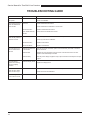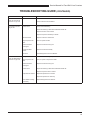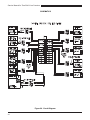
1
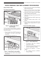
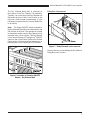
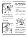
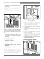
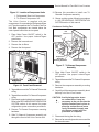
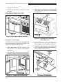
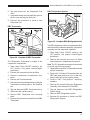
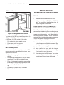
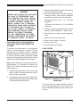
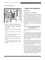
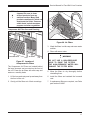
Service Manual
TACO BELL
I-LINE
COUNTER
Please read this manual completely before attempting
to install, operate or service this equipment
This document is prepared for trained Duke service technicians. It is not to be used by anyone not
properly qualified to perform these procedures.
This Service Manual is not all encompassing. If you have not been trained on servicing this product,
be sure to read the manual completely before attempting servicing. Be sure all necessary tools, test
equipment, and skills are available. Those procedures for which you do not have the proper skills
and test equipment must be performed only by a qualified Duke trained service technician.
This manual is copyright ©2011 Duke Manufacturing Company. All rights reserved. Reproduction without
written permission is prohibited. Duke is a registered trademark of the Duke Manufacturing Company.
Duke Manufacturing Company
2305 N. Broadway • St. Louis, MO 63102
800.735.3853 • 314.231.1130
Fax: 314-231-5074
www.dukemfg.com
P/N 219208B
Service Manual for Taco Bell I-Line Counters
IMPORTANT WARNING AND SAFETY INFORMATION
WARNING
READ THIS MANUAL THOROUGHLY BEFORE OPERATING, INSTALLING, OR
PERFORMING MAINTENANCE ON THE EQUIPMENT.
WARNING
FAILURE TO FOLLOW INSTRUCTIONS IN THIS MANUAL CAN CAUSE PROPERTY
DAMAGE, INJURY OR DEATH.
WARNING
DO NOT STORE OR USE GASOLINE OR OTHER FLAMMABLE VAPORS OR
LIQUIDS IN THE VICINITY OF THIS OR ANY OTHER APPLIANCE.
WARNING
DO NOT OPERATE THIS EQUIPMENT WITHOUT PROPERLY PLACING AND
SECURING ALL COVER AND ACCESS PANELS.
CAUTION
Observe the following:
•
Provide and maintain adequate minimum clearances from all walls and combustible materials.
•
Provide and maintain adequate clearance for air openings.
•
Keep the equipment area free and clear of combustible material.
•
Operate equipment only on the type of electricity indicated on the specification plate.
•
Retain this manual for future reference.
2
Service Manual for Taco Bell I-Line Counters
TABLE OF CONTENTS
TACO BELL I-LINE COUNTER SPECIFICATIONS..........................................................4
INSTALLATION.................................................................................................................4
LOCATION..................................................................................................................4
LEVELING...................................................................................................................4
STABILIZING...............................................................................................................4
ELECTRICAL CONNECTION.....................................................................................4
PARTS REMOVAL AND REPLACEMENT PROCEDURES..............................................5
MAIN CONTROL PANEL.............................................................................................5
Dry Channel Control Display.................................................................................5
Control Panel ON/OFF switches............................................................................5
DRY CHANNEL ..........................................................................................................6
General..................................................................................................................6
Relay Box..............................................................................................................6
Relay Box Components.........................................................................................7
Solid State Relay (SSR) Replacement..................................................................7
Transformer Replacement.....................................................................................8
Channel Assembly.................................................................................................8
TRI-CHANNEL COLD PAN.........................................................................................9
Evaporator.............................................................................................................9
Thermostat.............................................................................................................9
Tri-Channel Compressor Assembly.....................................................................10
Condenser Cooling Fan....................................................................................... 11
REFRIGERATED BASE UNIT (RBC)........................................................................ 11
Evaporator Fan Assembly.................................................................................... 11
RBC Thermostat..................................................................................................12
RBC Refrigeration System...................................................................................13
RBC Door Gaskets..............................................................................................13
RBC Door Adjustment..........................................................................................13
RECHARGING REFRIGERATION SYSTEM..................................................................14
TOOLS......................................................................................................................14
DUKE SERVICE BULLETIN NUMBER 26 –
REFRIGERATION SYSTEM EVACUATION........................................................14
DUKE SERVICE BULLETIN NUMBER 35 –
ACCESSING SEALED REFRIGERATION SYSTEMS........................................14
LOAD CENTER.........................................................................................................15
Circuit Breaker Replacement...............................................................................15
SERVICE INFORMATION...............................................................................................16
MAINTENANCE........................................................................................................16
Stainless Steel Care and Cleaning......................................................................16
Compressor Air Filter Care and Cleaning............................................................16
TROUBLESHOOTING GUIDE........................................................................................18
SCHEMATICS.................................................................................................................20
3
Service Manual for Taco Bell I-Line Counters
TACO BELL I-LINE COUNTER SPECIFICATIONS
MODEL
DESCRIPTION
VOLTAGE
SIZE
TBIL-RL-131
TBIL-LR-131
I-Line Counter Right to Left
I-Line Counter Left to Right
208 VAC 3 Phase
208 VAC 3 Phase
L:1313
L:1313
INSTALLATION
LOCATION
STABILIZING
The I-Line Counter is intended for indoor use only.
Be sure the chosen location has a floor strong
enough to support the total weight of the unit fully
loaded with food product. Reinforce the floor, if
necessary, to provide for maximum loading. For
the most efficient operation, be sure to provide
good air circulation.
Use the leg adjustments to ensure that the unit
is solid to the floor surface at all contact points.
Ensure that the unit does not “rock” when pressure
is applied to the top corners.
LEVELING
Be sure the unit is placed on a firm, flat surface/
floor. Check for cracks in flooring or tile and avoid
these areas if possible. If necessary, place support
pads, properly rated for the weight of the unit, to
“bridge” uneven or cracked flooring. Level the unit
accordingly using the leg adjusters.
4
ELECTRICAL CONNECTION
The I-Line Counter Unit requires 208VAC,
3 Phase, 50/60 Hz. Direct wiring I-Line Counter
Unit to the power supply must be performed by
a certified electrician and must comply with local
electrical codes for your municipality.
Service Manual for Taco Bell I-Line Counters
PARTS REMOVAL AND REPLACEMENT PROCEDURES
MAIN CONTROL PANEL
4. Remove the four Dry Channel Control Display
Board mounting screws.
Dry Channel Control Display
5. Remove the Dry Channel Control Display
Board through the front of the control panel.
6. Install the new Dry Channel Control Display
Board, reattach mounting screws.
7. Refer to the wire tags, and reconnect all wire
harnesses.
TRI
CHANN
EL
TACO
TOWER
TORTILL
A
GRILL
8. Place the Main Power ON/OFF switch in the
ON position.
DRY
CHANN
EL
PROG
9. Place Dry Channel power switch in ON
position.
Control
Display
10.Wait a minimum of 20 minutes. Monitor Dry
Channel Control Display Board for proper
operation.
Figure 1. Location of Dry Channel
Control Display
Control Panel ON/OFF switches
The Dry Channel Control Display is located on
the operator’s side of the I-Line Counter next to
the power switches.
1
1. Place the Main Power ON/OFF switch in the
OFF position. Use proper Lockout/Tagout
procedures.
TRI
CHAN
NEL
2. Lift control panel up and tilt it out.
2
TACO
TOWE
R
3
TORT
ILLA
GRILL
4
DRY
CHAN
NEL
PROG
Control
Switch
Panel
Figure 3. Control Switch Panel
TRI
CHAN
NE
L
TACO
TOWE
R
TORT
ILL
GRILLA
DRY
CHAN
NE
L
PROG
Mounting
Screws
Figure 2. Control Panel in open position.
1: Tri-Channel Cold Pan (120VAC,
Single Phase, 948W)
2: Taco Tower Infrared Heaters and Lights
(120VAC, Single Phase, 1840W)
3: Tortilla Grill (208VAC,
1200W)
3 Phase,
4: Dry Channel Warmer (208VAC,
3 Phase, 2100W)
3. Tag and unplug Dry Channel Control Display
Board wiring.
5
Service Manual for Taco Bell I-Line Counters
The four switches on the control panel are
labeled Cold Pan, Taco Tower, Tortilla Grill and
Dry Channel.
1. Place the Main Power ON/OFF switch in the
OFF position. Use proper Lockout/Tagout
procedures.
2. Open the switch panel.
3. Remove the protective cover from the back of
the switches.
4. Tag and disconnect the wires from the suspect
switch.
5. Test the switch for continuity; it should read 0
ohms in the ON Position. Replace it if it reads
open or a high resistance.
6. Remove two screws on front of control panel
to remove faulty switch.
7. Replace switch with properly rated switch.
The Dry Channel unit is mounted above the
compressor units. The Dry Channel unit must be
removed from the I-Line Counter in order to service
a channel assembly or the relay box.
1. Place Main Power ON/OFF switch in the
OFF position. Use proper Lockout/Tagout
procedures.
2. Open the I-Line Counter Control Panel
3. Tag and unplug the Dry Channel cables from
the Dry Channel Control Display.
4. Tag and disconnect Dry Channel power
cord.
5. Remove the hardware that holds the Dry
Channel unit in place in the I-Line Counter.
6. Carefully lift the Dry Channel unit free of
the I-Line Counter: Do not damage the Dry
Channel’s cabling or power cord.
9. Install protective cover.
7. Reverse this procedure to reinstall the Dry
Channel unit after servicing it or to install a
replacement unit.
10.Close control panel.
Relay Box
8. Refer to tags, and reconnect wires.
11.Restore I-Line Counter to service and check
for proper switch operation.
DRY CHANNEL
Note: The following procedures are performed
while the Dry Channel unit is removed from the
I-Line Counter.
General
Dry Channel Unit
DANGER
POWER
ON
O
Figure 4. Location of the Dry Channel Unit
6
OFF
Figure 5. Dry Channel Relay Box
Service Manual for Taco Bell I-Line Counters
The Dry Channel Relay Box is mounted on
the bottom of the Dry Channel Tub assembly.
Typically, it is on the side of the Dry Channel unit
that faces the front of the I-Line Counter on the
right side. Under normal circumstances, it is not
necessary to replace the Dry Channel Relay Box
in its entirety.
Relay Box Components
Note: The Power ON/OFF switch mounted on
the Dry Channel Relay Box unit must remain in the
ON position at all times. The operator is not able
to access this switch once the Dry Channel unit is
mounted in the I-Line Counter. The Dry Channel
unit is turned ON and OFF using the 4th ON/OFF
switch on the Control Panel. Refer to the Control
Panel section of this manual for instructions on
replacing the Control Panel ON/OFF switches.
Figure 7. Relay Box with cover removed
Remove the four screws holding the Dry Channel
Relay Box cover in place.
TRI
CHAN
NEL
TACO
TOWE
R
TORTI
LLA
GRILL
DRY
CHAN
NEL
PROG
ON
O
OFF
Figure 6. Location of Operator ON/OFF
Switch – Dry Channel Unit
7
Service Manual for Taco Bell I-Line Counters
Solid State Relay (SSR) Replacement
Figure 9. 24Volt Step Down Transformer
The step down transformer utilizes a tapped
primary the allows the Dry Channel unit to be
operated at either 208VAC or 240VAC.
1. Tag and disconnect the primary power cord
from the transformer; also tag the terminals
on the transformer to ensure the power cord
will be connected at the correct voltage for the
I-Line Counter.
2. Tag and disconnect wires to the secondary.
3. Remove four nuts attaching transformer
to the studs in the Relay Box and remove
Transformer.
Figure 8. Solid State Relay (SSR)
The I-Line Counter uses Dry Channel Model HDC3
Components. There are 6 Solid State Relays in
the this unit. Test each relay to determine which
one is causing the fault.
4. Reverse procedure to install a new Transformer.
Ensure that the power cable is connected to the
correct terminals on the transformer to math
the operating voltage of the I-Line Counter.
Channel Assembly
Channel
Assembly
1. Label and disconnect wires from SSR to be
replaced.
2. Remove two screws attaching SSR to Relay
Box and remove SSR.
3. Reverse procedure to install a new SSR.
Transformer Replacement
Tub
Figure 10. Dry Channel HDC3 Tub and
Channel Assembly
The Heat Elements, Hi-Limit Thermostats and
RTDs are imbedded in a foil wrap that is attached
to the bottom of each Channel Assembly. These
parts are not serviceable in the field. The entire
Channel Assembly must be replaced in the event
of a failure of any of these components.
8
Service Manual for Taco Bell I-Line Counters
TRI-CHANNEL COLD PAN
Figure 11. Dry Channel Tub Assembly
1. Remove six screws (three on each side)
attaching the Dry Channel Top Frame to its
tub assembly.
2. Lift the Dry Channel Top Frame off the tub
assembly.
3. Lift the Channel Assembly out of the tub. Use
care when pulling the Channel Assembly’s
wire harness out of the tub assembly.
4. Using an ohmmeter, test the resistance across
the entire heating element. It should read
approximately 248 ohms. Also test the RTD
circuit, its normal reading is approximately
1,000 ohms. Replace the channel assembly
if either the heater circuit or RTD circuit is
reading out of tolerance.
5. To install a new Channel Assembly, reverse
steps 1 through 3.
Note: End channels are a different assembly from
center channels. When replacing an end channel
use part 171263SED. When replacing the center
channel use part 171262SED.
Figure 12. Tri-Channel Cold Pan Unit
The Tri-Channel Cold Pan is located in the center of
the I-Line Counter Unit above the refrigerator. Refer
to Duke Manufacturing Service Bulletin Number
26 and the RECHARGING REFRIGERATION
SYSTEM section of this manual before completing
Evaporator replacement procedures.
Evaporator
The evaporator coils embedded in the body of
the Tri-Channel Cold Pan are not serviceable.
Replace the entire upper body if an evaporator
leak or failure occurs.
1. Place Main Power ON/OFF switch in the
OFF position. Use proper Lockout/Tagout
procedures.
2. Evacuate coolant following procedures in the
RECHARGING REFRIGERATION SYSTEM
section of this manual.
3. Disconnect the coolant tubing.
4. Remove Tri-Channel mounting hardware.
5. Pull Tri-Channel Pan assembly out of I-Line
Counter Unit.
6. Install new Tri-Channel Pan.
7. Braze coolant lines from Tri-Channel Pan to
Compressor lines.
8. Charge cooling system following procedures
in the RECHARGING REFRIGERATION
SYSTEM section of this manual.
9
Service Manual for Taco Bell I-Line Counters
9. Place the Main Power ON/OFF switch in the
ON position.
10.Place the Tri-Channel Power switch in the ON
position.
11.Check Tri-Channel Cold Pan for proper
operation.
Thermostat
Figure 14. Tri-Channel Thermostat and
Mounting Bracket
8. Reverse this procedure to install new TriChannel Thermostat; be careful not to kink
capillary tubing when reconnecting it.
9. Place the Main Power ON/OFF switch in the
ON position.
Figure 13. Location of Cold Pan Thermostat
The Tri-Channel Cold Pan thermostat is located in
the compressor compartment behind the louvered
vent.
1. Place Main Power ON/OFF switch in the
OFF position. Use proper Lockout/Tagout
procedures.
10.Place the Tri-Channel Power switch in the ON
position.
11.Set the Thermostat based on guidelines
provided by Subway®.
12.Allow the Tri-Channel unit to cool for
approximately 20 minutes before performing
a temperature check on each channel.
2. Remove the louvered vent.
13.Adjust Thermostat as required until proper
temperature is achieved.
3. Remove both air filters.
Tri-Channel Compressor Assembly
4. Remove the front panel.
5. Tag and disconnect the Tri-Channel Thermostat
wiring.
6. Disconnect capillary tube from the
thermostat.
7. Remove Tri-Channel Thermostat from
mounting bracket.
Note: The Tri-Channel Thermostat is mounted
to the side of the Refrigerated Base Unit (RBC)
Condenser Housing. Do not confuse this
thermostat with the one used for the RBC.
10
Service Manual for Taco Bell I-Line Counters
Figure 15. Location of Compressor Units
1: Refrigerated Base Unit Compressor
2: Tri-Channel Compressor Unit
The I-Line Counter is supplied with two
compressors. One operates the Refrigerated Base
unit. The other operates the Tri-Channel Cold Pan
Unit. Both compressors are located below the
control panel behind the service panel.
1. Place Main Power ON/OFF switch in the
OFF position. Use proper Lockout/Tagout
procedures.
10.Reverse this procedure to install new TriChannel Compressor assembly
11.Charge cooling system following procedures
in the RECHARGING REFRIGERATION
SYSTEM section of this manual.
Condenser Cooling Fan
Fan
Shroud
Compressor
Assembly
2. Remove the louvered vent.
3. Remove the air filters.
4. Remove the front panel.
Fan
Shroud
Screws
Compressor
Assembly
Mounting Hardware
Fan Mounting
Bracket Screws
Figure 17. Tri-Channel Compressor
Assembly
1. Place Main Power ON/OFF switch in the
OFF position. Use proper Lockout/Tagout
procedures
2. Tag and disconnect theTri-Channel Compressor
wiring.
Figure 16. Front Panel Removed
5. Tag and disconnect the Tri-Channel Thermostat
wiring.
6. Tag and disconnect theTri-Channel Compressor
wiring.
7. Disconnect coolant tubing from evaporator unit.
Refer to the RECHARGING REFRIGERATION
SYSTEM section of this manual for proper
refrigeration system evacuation procedures.
8. Remove Tri-Channel Compressor mounting
hardware.
9. Slide Tri-Channel Compressor assembly out
through the front of the I-Line Counter Unit.
3. Remove the compressor assembly mounting
hardware.
4. Carefully pull the compressor assembly about
half way out of the I-Line Counter.
CAUTION: Avoid placing undue stress
on coolant lines. It may be
necessary to the cut wire ties the
hold the coolant lines in place to
allow the coolant lines to move
freely. Remember to apply new
wire ties as needed once the
procedure is completed.
5. Disconnect the tag the fan wiring.
6. Remove fan mounting bracket screws and the
fan shroud screws.
11
Service Manual for Taco Bell I-Line Counters
7. Remove fan assembly.
8. Reverse this procedure to install the new fan
assembly.
3. Remove the louvered panel on the inside wall
of the RBC to gain access to the Evaporator
Fan Assembly.
REFRIGERATED BASE UNIT (RBC)
Figure 18. Refrigerated Base Unit (RBC)
Evaporator Fan Assembly
The Evaporator Fan Assembly is accessed through
the louvered panel on the inside of the RBC. The
assembly is equipped with two fans.
1. Place Main Power ON/OFF switch in the
OFF position. Use proper Lockout/Tagout
procedures.
Figure 20. Evaporator Fan Assembly –
Louver Removed
4. Remove the screws securing the Evaporator
Fan Assembly to the Evaporator Assembly.
5. Carefully lift the Evaporator Fan Assembly out
of the Evaporator Assembly. Be careful not to
pull too hard on the fan wiring.
2. Open the RBC doors and remove the shelf/
shelves for easier access to louvered panel.
Figure 19. Location of Louvered Panel
12
Figure 21. Exploded View –
Evaporator Fan Assembly
Service Manual for Taco Bell I-Line Counters
6. Tag and disconnect the Evaporator Fan
wires.
RBC Refrigeration System
7. A separate bracket secures each fan; remove
the two nuts securing the faulty fan.
8. Reverse this procedure to install a new
Evaporator Fan
RBC Thermostat
Figure 23. Complete RBC Refrigeration Unit
The RBC refrigeration unit is a complete assembly
that includes the condenser assembly, compressor
assembly and the evaporator assembly.
Figure 22. Location of RBC Thermostat
The Refrigerator Thermostat is located in the
compressor compartment.
1. Place Main Power ON/OFF switch in the
OFF position. Use proper Lockout/Tagout
procedures.
2. Remove the louvered vent and air filters.
3. Remove compressor compartment front
panel.
4. Remove the Thermostat knob.
5. Remove the two hex-head screws holding the
Thermostat mounting plate to the electrical
box.
6. Tag and disconnect RBC Thermostat wiring.
7. Disconnect the capillary tubing.
8. Remove RBC Thermostat from mounting
plate.
9. Reverse this procedure to install the new RBC
Thermostat.
1. Place Main Power ON/OFF switch in the
OFF position. Use proper Lockout/Tagout
procedures.
2. Remove the louvered vent cover, air filters
and compressor compartment front panel.
Note: The Tri-Channel thermostat must be moved
out of the way for this procedure.
3. Tag and disconnect the Tri-Channel thermostat
wiring if necessary.
4. Detach the Tri-Channel Thermostat from the
RBC side panel and move it out of the way,
being careful not to kink capillary tubing.
5. Remove RBC Refrigeration assembly
hardware.
6. Remove the screws holding the Evaporator
assembly to the side panel of the RBC.
7. Tag and disconnect the RBC Refrigeration
System wiring.
8. Remove RBC Refrigeration system.
9. Reverse this procedure to install new RBC
Refrigeration System.
13
Service Manual for Taco Bell I-Line Counters
RBC Door Gaskets
RECHARGING
REFRIGERATION SYSTEM
TOOLS
•
Standard hand and refrigeration tools
•
Refrigerant Type: R-134A or R-404A.
Refer to equipment identification plate for
proper refrigerant replacement.
DUKE SERVICE BULLETIN NUMBER 26 –
REFRIGERATION SYSTEM EVACUATION
Figure 24. Refrigerator Door Gasket
The doors of the RBC are two different sizes. A
173" (part: 216645) gasket is required for one and
a 193" (part: 216636) gasket for the other.
1. Pull gasket out of door panel groove.
2. Press new gasket into groove.
3. Ensure door seals properly.
RBC Door Adjustment
Over time and with repeated use, the RBC
doors may begin to sag. When this occurs, door
adjustment is required.
1. Open the sagging door to its full open
position.
2. Check hinges for tightness. If they are loose,
snug them up but don’t overtighten them.
3. Place a flat-headed screwdriver against the
inside edge of the top hinge, tap it with a small
hammer, using light taps until the door lines
up.
4. Repeat for the bottom hinge if needed.
5. Tighten all of the hinge screws
14
Note: Prior to refrigeration system service, special
care must be taken during the evacuation process
to remove air, moisture and other non-condensable
gasses from the system. Duke Manufacturing
recommends the following triple evacuation
method. Failure to follow this procedure may result
in poor refrigeration system performance.
1. Evacuate system to 1500 microns.
2. Break vacuum to 2 psig with dry nitrogen.
If dry nitrogen is unavailable, use same type
of refrigerant as used in system.
3. Evacuate system to 1500 microns.
4. Break vacuum to 2 psig with dry nitrogen.
If dry nitrogen is unavailable, use same type
of refrigerant as used in system.
5. Evacuate system to 500 microns. The system
is now ready to receive refrigerant charge
according to information on data plate.
Service Manual for Taco Bell I-Line Counters
WARNING
NEVER USE OXYGEN OR ACETYLENE
IN PLACE OF REFRIGERANT AND
DRY NITROGEN FOR LEAK TESTING.
A VIOLENT EXPLOSION MAY RESULT,
CAUSING PERSONAL INJURY OR
DEATH. ALWAYS USE A PRESSURE
REGULATOR WHEN USING NITROGEN
TO PRESSURE TEST. FAILURE TO
DO SO WILL RESULT IN EXTREMELY
HIGH PRESSURE, WHICH COULD
EXCEED THE BURST PRESSURE
OF THE COMPRESSOR OR OTHER
SYSTEM COMPONENTS AND RESULT
IN PERSONAL INJURY OR DEATH.
3. After completing repair, evacuate system using
the triple evacuation method.
4. After completing proper evacuation method,
recharge system, using proper refrigerant
according to information on the data plate.
Refrigerated Base Unit: 8 oz of R-134a
refrigerant
Tri-Channel Cold Pan Unit: 12 oz of R404a
refrigerant
5. Continue crimping process hose just below
temporary valve and again 2" below crimp.
6. With crimp tool in place, remove temporary
valve.
7. Braze shut end of process hose.
8. Allow to cool for about 5 minutes.
DUKE SERVICE BULLETIN NUMBER 35 –
ACCESSING SEALED REFRIGERATION
SYSTEMS
9. Remove crimp tool.
To analyze the performance of a refrigeration
system, record temperature readings. Convert
temperature into pressure using a standard
pressure/temperature chart. When it is necessary
to service a factory-sealed refrigeration system
and return it to its properly sealed condition, strictly
adhere to the following approved procedure.
LOAD CENTER
10.Check brazed end for leaks.
Note: Ensure that there is enough process hose
(approximately 12") available to complete the
repair. If not, install a new process hose before
repair sequence.
1. Install a temporary access valve on the high
and low sides of process hoses as close to
factory crimps as possible.
2. Use temporary valves to perform repair. Note:
Duke Manufacturing will not reimburse the cost
of permanently installed valves.
Figure 25. Location of I-Line Counter
Load Center
The Load Center is located behind the cabinet
door on the right side of the I-Line Counter Unit.
It is the electrical distribution center for the I-Line
Counter.
15
Service Manual for Taco Bell I-Line Counters
Circuit Breaker Replacement
SERVICE INFORMATION
MAINTENANCE
Stainless Steel Care and Cleaning
Figure 26. Location of Circuit Breakers
1. Place Main Power ON/OFF switch in the
OFF position. Use proper Lockout/Tagout
procedures.
2. Tag and disconnect the affected circuit breaker
wires.
3. Pull the circuit breaker out of its mounting
slots.
4. Push the new circuit breaker into the slot;
ensure that it locks into position.
5. Referring to the tags, reconnect the wires.
6. Place Main Power ON/OFF switch in the ON
position.
7. Refer to TROUBLESHOOTING section
if replacement breaker does not solve
problem.
Stainless steel contains 70-80% iron. Iron will rust.
It also contains 12-30% chromium. Chromium
forms an invisible, passive film over the steel
surface and acts as a shield against corrosion.
As long as the protective film remains intact, the
metal will not corrode. However, if the film is broken
or contaminated, outside elements can begin to
break down the steel and begin to form rust or
discoloration. To prevent rust and discoloration
on stainless steel, several important steps are
required.
CAUTION: Never use steel wool pads, wire
brushes, scrapers or cleaners
containing abrasives.
Avoid cleaning solutions that contain alkaline or
chloride.
Use non-alkaline based or non-chloride cleaning
solutions. Anything containing chloride will damage
the protective film on stainless steel. Chlorides
are found in household and industrial cleaners
and also in hard water and salts. If a chloride or
alkaline cleaner has been used, rinse repeatedly
and dry thoroughly.
Always use only soft cloths or plastic scouring pads.
For routine cleaning, use warm soapy water. For
stubborn stains use a non-abrasive cleanser. For
heavy grease use a degreaser. For best results,
rub with the grain of the steel.
Pitting and cracking are early signs of stainless
steel breakdown. Special stainless steel cleaners
can restore and preserve the protective film. If
signs of breakdown appear, thoroughly clean
and dry all surfaces. Begin regular application of
a high quality stainless steel cleaner according to
the manufacturer’s instructions. Again, always rub
with the grain of the steel for best results.
16
Service Manual for Taco Bell I-Line Counters
CAUTION: Never use an acid-based
cleanser! Be sure to clean
all food products from any
stainless surface. Many food
products contain acid, which can
deteriorate the finish. Common
acidic foods include tomatoes,
peppers and other vegetables.
Compressor Air Filter Care and Cleaning
Figure 28. Air Filters
3. Wash the filters in mild soap and warm water
solution.
4. Rinse with warm water.
Louvered Panel
Air Filters
Figure 27. Location of
Compressor Air Filters
WARNING
DO NOT USE A HIGH-PRESSURE
HOSE TO RINSE THE FILTERS.
THE HIGH-PRESSURE WATER WILL
DAMAGE THE FILTER MESH.
The Compressor Air Filters are located behind
the large louvered vent mounted on the front of
the unit. Clean the air filters with mild soap and
water on a monthly basis.
5. Allow the filters to dry thoroughly before
reinstalling them.
1. Lift the louvered vent panel up and away from
the front of the unit.
6. Install the filters and reattach the louvered
vent.
2. Gently pull the filters out of their mountings.
7. If replacement filters are required, use Duke
part number 214947.
17
Service Manual for Taco Bell I-Line Counters
TROUBLESHOOTING GUIDE
SYMPTOM
POSSIBLE CAUSE
I-Line Counter Unit does
not operate.
No Power
I-Line Counter Unit has
power but Tortilla Grill
does not heat.
No Power
REMEDY
Make sure Main Power ON/OFF switch is in ON position.
Check Circuit Breaker.
Check Tortilla Grill Power Switch.
Check Tortilla Grill Circuit Breaker in Load Center.
Bad Power Switch
Replace Tortilla Grill Power Switch.
Open Tortilla Grill Heat
Element
Have customer contact APW for service.
I-Line Counter Unit has
power but Dry Channel
Unit does not heat.
No Power
Make sure Dry Channel Power Switch is in the ON position.
Check Dry Channel Circuit Breaker.
Bad Power Switch
Replace Power Switch.
Bad Control Board
Replace Control Board.
Dry Channel Unit is on
but one channel does
not heat.
Defective Heat Element
or Thermostat
Test heat circuit with ohmmeter; replace Channel Assembly if test fails. It should be
around 124 ohms.
Defective RTD
Test RTD at room temperature using ohmmeter. It should read around 1K ohms.
Replace Channel Assembly if test fails.
Defective Relay
Test relay when voltage is applied to input; output should be closed. Replace if output
is open.
Dry Channel Unit
appears to be working
but has no display indication.
Defective Display Panel
Replace the Display Panel.
I-Line Counter Unit has
power but Taco Tower
does not heat or light.
No Power
Make sure Taco Tower Power Switch is in the ON position.
Check Taco Tower Circuit Breaker.
Taco Tower lights come
on but it does not heat.
Failed Infrared Heater
Have customer contact Hatco for service.
18
Service Manual for Taco Bell I-Line Counters
TROUBLESHOOTING GUIDE (CONTINUED)
SYMPTOM
I-Line Counter Unit has
power but Tri-Channel
Unit does not get cold.
No Power
Tri-Channel Unit does
not get cold.
Coolant Leak
I-Line Counter has
power but Refrigeration
Unit does not get cold.
Make sure Tri-Channel Power Switch is in the ON position.
Check Tri-Channel Circuit Breaker.
REMEDY
POSSIBLE CAUSE
Check Thermostat setting.
Repair leak referring to Duke Service Bulletin Number 26.
Replace Cold Pan Unit if needed.
Replace Compressor Assembly if needed.
Bad Thermostat
Replace Tri-Channel Thermostat.
Dirty Compressor Air
Filter
Clean or replace Air Filter.
Failed Condenser
Cooling Fan
Replace Condenser Cooling Fan.
Condenser Motor
Failure
No Power
Replace Condenser Assembly.
Check Refrigerator Unit Circuit Breaker.
Faulty Thermostat
Check Thermostat setting. Replace Thermostat.
Dirty Compressor Air
Filter
Clean or replace Compressor Air Filter.
Failed Condenser
Cooling Fan
Replace Condenser Cooling Fan.
Coolant Leak
Repair leak referring to Duke Service Bulletin Number 26.
Evaporator Fan Failure
Door Gaskets Leaking
Excessively.
Replace Compressor Unit if needed.
Replace Evaporator Unit if needed.
Replace Evaporator Fan Assembly.
Replace Refrigerator Door Gaskets.
19
Service Manual for Taco Bell I-Line Counters
SCHEMATICS
Figure 29. Circuit Diagram
20
Service Manual for Taco Bell I-Line Counters
PANEL #1
TACO BELL I-LINE COUNTER
125A 24P
120/208V - 3PH - 4W - S/N
70A MINIMUM PANEL AMPERAGE
POSITION
NUMBER
CIRCUIT
NUMBER
BRKR.
SIZE
ITEM # /
EQUIPMENT SERVED
LOAD
(VA)
PHASE
WIRE
LOAD
(VA)
EQUIPMENT
VOLTAGE
ITEM # /
EQUIPMENT SERVED
BRKR.
SIZE
1
3
5
7
9
11
13
15
17
19
21
23
1
15
TACO GRILL
208
1200
720
3300
120
208
REFRIGERATOR
MELTER
15
20
7
8
DC3A
208
2100
STAGER
LEFT MONITOR
TOP RECEPTACLE
HATCO H24T
120
120
120
120
820
1440
1920
1840
A
B
C
A
B
C
A
B
C
A
B
C
2
15
3
4
5
6
20
15
20
20
1920
948
1920
120
120
120
RIGHT MONITOR
COLD PAN
BOTTOM RECEPTACLE
20
15
20
9
10
11
5760 VA
A
6908 VA
B
5460 VA
C
3 PHASE PANEL BOX
EQUIPMENT
VOLTAGE
18128
CIRCUIT POSITION
NUMBER NUMBER
2
4
6
8
10
12
14
16
18
20
22
24
KVA :TOTAL LOAD
Figure 30. Load Center Diagram
21
Service Manual for Taco Bell I-Line Counters
22
Service Manual for Taco Bell I-Line Counters
23
Service Manual for Taco Bell I-Line Counters
Duke Manufacturing Company
2305 N. Broadway • St. Louis, MO 63102
800.735.3853 • 314.231.1130
Fax: 314-231-5074
www.dukemfg.com
24
P/N 219208