1
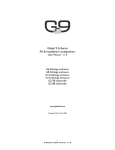
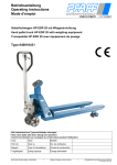
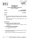
Operating Instructions
Parts List
Pallet Truck with Scale SAC25
Note: Operator MUST read and understand this operating instructions before use
this Hand Pallet Truck.
Thank you for using our pallet truck with Scale. Your pallet truck with Scale is made of high quality steel
and is designed for the horizontal lifting and transport of loads on a pallet or standardized containers on
a level, fixed base. For your safety and correct operation, please carefully read this instruction and the
display unit handbook (METTLER TOLEDO) “IND221 & IND226 Industry Terminal User/Service
Manual” before using it.
NOTE: All of the information reported herein is based on data available at the moment of printing. We
reserves the right to modify our own products at any moment without notice and incurring in any sanction.
So, it is suggested to always verify possible updates.
1. GENERAL SPECIFICATIONS
Capacity
Fork Height Raised
Fork Height Lowered
Fork Length
Width Across Forks
Individual Fork Width
Roller Size
Mail Wheel Size
Environment
Operating temperature
2000KG / 4400LBS
200MM / 8in
190MM / 7 3/4in
88MM / 3-1/2in
76MM / 3in
1150MM / 45in or 1220MM / 48in
568MM / 22-3/8in or 703MM / 27-11/16in
178MM / 7in
Ø74x70MM / Ø2-29/32x 2-3/4in
Ø64x70MM / Ø2-1/2x 2-3/4in
Ø180X50 / Ø7-1/4 x 2in
General purpose, dry
-10oC to 40oC (14oF to 104oF) with 10 to 95% relative humidity
2.
PRE-OPERATION PROCEDURE
2.1
Attaching the display unit(G228B)
A) Remove 4pcs screws(G228B-7) , take
away the cover board (G228B-6).
B) Remove 2pcs screws (G227B) from the
head of the fork frame(G201B).
C) Set the fixation box (G228B) onto the
head of pallet truck with your one hand,
and the other hand tighten the screws
(G227B).
D) Connect the “D-Sub Male connector “ and
the “D-Sub Female connector” together.
E) Close the cover board (G228B-6), then
tighten the screws (G228B-7).
The display unit is now fixed.
Fig. 1
2.2 To attach draw-bar to pump unit
When attaching the handle, you had better squat just behind the
pallet truck. Then you:
2.2.1 Insert the draw-bar onto the pump piston (303), then use a
hammer to insert the axle with hole (G105) into the hydraulic pump
and draw-bar from the right to left. (See fig. 2 ).
2.2.2 Let control handle(G117) to the ‘LOWER’ position, then pass
1
Fig. 2
the adjusting nut(G104), adjusting bolt(G103) and chain(G102) through the hole of axle(G105) with your
hand (See fig. 3).
2.2.3 Press the draw-bar (G110) down, take
away the pin which fix the Spring
Cap(301).
2.2.4 Let the control handle (G117) on ‘RAISE’
position, then raise the lever plate (319)
with the pin and insert the adjusting
bolt(G103) into the front slot of lever plate
(319), note to keep the adjusting nut
(G104) on the under side of the lever
plate.
2.2.5 Use a hammer to tap another elastic pin
(G106) into the axle with hole (G105).
The draw-bar is now assembled to the pump.
Fig. 3
3. TO ADJUST RELEASE DEVICE
On the draw-bar of this pallet truck, you can find the control handle(G117) which can be regulated in
three positions :
Raise
-handle down
Drive position -handle in center position
Lower
-handle up, the lever moves back the drive position when released.
If however they have been changed, you can adjust according to following step:
3.1 If the forks elevate while pumping in the DRIVE position, turn the adjusting nut (G104) on the
adjusting bolt(G103) or screw(318) clockwise until pumping action does not raise the forks and the
DRIVE position functions properly.
3.2 If the forks descend while pumping in the DRIVE position, turn the nut(G104) or screw(318)
counter-clockwise until the forks do not lower.
3.3 If the forks do not descent when the control handle (G117) is in the LOWER position, turn the
nut(G104) or screw (318) clockwise until raising the control handle(G117) lowers the forks. Then
check the DRIVE position according to item 3.1 and 3.2 to be sure the nut (G104) and screw(318) is
in the proper position.
3.4 If the forks do not elevate while pumping in the RAISE position, turn the nut (G104) or screw (318)
counter-clockwise until the forks elevate while pumping in the RAISE position. Then check the
LOWER and DRIVE position according to item 3.1, 3.2 and item 3.3.
4. MAINTENANCE
The pallet truck is largely maintenance-free.
4.1 OIL
Please check the oil level every six months. The oil can be hydraulic oil: ISO VG32, its viscosity should
be 30cSt at 400 C, total volume is about 0.4lt.
4.2 TO BANISH THE AIR
2
The air may come into the hydraulic oil because of transportation or pump in upset position. It can
cause that the forks do not elevate while pumping in the RAISE position. The air can been removed in
the following way: let the control handle (G117) on the LOWER position, then move the draw-bar up
and down for several times.
4.3 DAILY CHECK AND MAINTENANCE
Daily check of the pallet truck can limit wear as much as possible. Special attention should be paid to
the wheels, the axles, as thread, rags, etc. It may block the wheels. The forks should be unloaded and
lowered in the lowest position when the job is over.
4.4 LUBRICATION
All bearings and shafts are provided with long-life grease at the factory. You only need provide with
long-life grease at monthly intervals or after each time the truck is cleaned thoroughly to the lubrication
points.
4.5 MAINTENANCE OF DISPLAY UNIT
See METTLER TOLEDO “IND221 & IND226 Industry Terminal User/Service Manual”.
5
GUIDE TO SAFETY OPERATION
5.1 Disconnect all power to the pallet truck with scale before installing, servicing, cleaning or removing
the fuse. Failure to do so could result in bodily harm and/or property damage.
5.2 To pull the truck, always move the control handle into the drive position. This makes the draw-bar
easier to move and depressurizes the pump section of the hydraulics. This preserves the hydraulic
seals and the valve components. A long service life can be expected.
5.3 Operator should read all warning signs and instructions here and on the pallet truck before using
this truck with scale.
5.4 Do not operate a pallet truck with scale unless you are familiar with it and have been trained or
authorized to do so.
5.5 Do not operate a pallet truck unless you have checked its condition. Give special attention to the
wheels, the draw-bar unit, the fork unit, the lever plate, etc.
5.6 Do not use on a slopping ground.
5.7 Do not take up any people on the pallet truck when moving.
5.8 The operator had better take on gloves for labor protecting.
5.9 When the goods have been transported, all people should be away from the forks for 600mm.
5.10 Do not load goods like fig. 5/B, the barycenter of the goods should be on the midline of pallet truck
with scale.
5.11 Do not load over maximum capacity.
5.12 At others special condition or place, the operator should be carefully to operate the pallet truck.
3
6.
TROUBLES SHOOTING
No
Trouble
Clause
1 The forks can not -The hydraulic oil is not enough.
be up the max.
height.
-Without hydraulic oil.
The forks can not -The oil has impurities.
2 be lifted up.
-The nut (G104) is too high, keep the
pumping valve open.
-Air come into the hydraulic oil.
-The piston rod(328) or pump body(322B)
is deformed resulting from partial loading
slanting to one side or over-loading.
-The fork was kept in the high position for
3 The forks can not long time with piston rod bared to arise in
be descended.
rusting and jamming of the rod.
4
5
6
7
8
Leaks
The
fork
descends without
the release valve
worked.
The result of scale
is incorrect.
Nothing is
displayed by the
terminal.
Appear error
cods:E1, E2,
E3…..
Fixing Methods
-Pour in the oil.
-Fill in the oil.
-Change the oil.
-Adjust the nut(G104) or screw
(318) (see item 3.4)
-Banish the air.(see item 4.2)
-Replace the piston rod (328) or
pump body (322B).
-Keeping the fork in the lowest
position if not using, and pay
more attention to lubricate the
rod.
-The adjusting nut (G104) or screw (318) is -Adjust the nut (G104) or screw
not in correct position.
(318) (see item 3.3)
-Sealing parts worn or damaged.
-Replace with the new one.
-Some part cracked or worn into small.
-Replace with the new one.
-The impurities in the oil cause the release -Replace with new oil.
valve to be unable to close tight.
-Some parts of hydraulic system is cracked -Inspect and replace the waste
or bored.
parts.
-Air come into the oil.
-Banish the air. (See item 4.2)
-Sealing parts worn or damaged.
-Replace with the new one.
-The adjusting nut (G104) or screw (318) is -Adjusting the nut (G104) or
not in the correct position.
screw (318). (See item 3.2)
- The bolts (G225B) scrape the platform
- Adjust the bolts (G225B)
(G226B)
- The platform scrapes the fork (G201B)
-Face lifting the platform.
- The battery power is too lower.
- Replace with new one.
See METTLER TOLEDO “IND221 &
IND226 Industry Terminal User/Service
Manual”
NOTE: DO NOT ATTEMP TO REPAIR THE PALLET TRUCK UNLESS YOU ARE TRAINED AND
AUTHORIZED TO DO SO.
7.
WEIGHING OPERATION
7.1 Preparation: Put the control lever in the LOWER position and lower the truck to lowest position.
7.2 Press the “Print” Key until the backlight on. After the indicator being checked by itself,it display
“0Kg”.
7.3 Weighing method for gross weight: Put the forks under pallet and judge by eyes it will be balanced
load. Put the control handle in the Lower position, pump the handle to make the fork be raised until
you can make sure the pallet leave ground. The stable reading of the indictor is the gross weight of
the goods (total weight of the pallet and the goods).
7.4 Net weight weighing method: To weigh the goods packed in the same type standard pallet, please
operate as following:
7.4.1 Weigh single standard pallet, for example: weight of pallet: 40Kg.
7.4.2 Press the key of “TARE”, then the indicator display “0kg”.
7.4.3 Remove the pallet from the fork, then the indicator display “-40kg”.
4
7.4.4 Weigh the palletized goods according the method of 7.3, the stable reading of the indicator is
net weigh of the goods.
7.5 The Switch of kilogram and pound. When the reading of indicator is in unit of kilogram, press
key of “FUNCTION”, the unit of reading switch to pound. Press the key of “FUNCTION” again,
unit of reading switch to kilogram again.
7.6 Turn off the Indicator: When the Indicator works normally, press the key of “PRINT” until
Indicator display “OFF”. Loosen the key will turn off the Indicator.
8.
Wiring diagram of scale, junction box, sensor
Note: Adjust corresponding relation
R12 Adjust Sensor 1
R4
Adjust Sensor 2
R16 Adjust Sensor 3
R8
Adjust Sensor 4
5
the
the
the
the
6
No.
G101
G102
G103
G104
G105
G106
G107
G108
G109
G109A
G110
Description
Release Rod
Chain
Adjusting Bolt
Adjusting Nut
Axle with Hole
Elastic Pin
Bushing
Roller Pin
Pressure Roller
Bushing
Draw-bar
Qty.
1
1
1
1
1
2
2
1
1
1
1
No.
G111
G112
G113
G114
G115
G116
G117
G118
G119
G120
G121
7
Description
Stop Rubber
Elastic Pin
Blade Spring
Spring
Elastic Pin
Elastic Pin
Control Handle
Roller
Elastic Pin
Pin
Pull Board
Qty.
1
1
1
1
1
1
1
1
1
1
1
Fork Frame Unit
No.
G201B
G202B
G203B
G204B
G205B
G206B
G207B
G208B
G209B
G210B
G211B
G212B
G213B
G214B
G215B
G216B
G217B
G218B
G219B
G220B
Description
Fork Frame
Box of Cable
Elastic Washer
Screw
Rock - Arm
Joint
Shaft
Nut
Pushing Rod
Long Shaft
Elastic Pin
Holding Seat
Load Cell
Pin
Screw
Shaft
Elastic Pin
Frame of Roller
Washer
Elastic Pin
Qty.
1
1
2
2
1
2
2
2
2
1
1
4
4
4
8
2
2
2
4
2
No.
G221B
G222B
G223B
G224B
G225B
G226B
G227B
G228B
G202
G204
G205
G206
G207
G208
G215
G222
G223
G228
G229
8
Description
Shaft
Linking Plate
Axle for Roller
Loading Roller
Bolt
Platform
Screw
Display Unit
Elastic Pin
Bushing
Shaft
Grease Cup
Bushing
Retaining Ring
Elastic Pin
Washer
Bearing
Grease Cup
Washer
Qty.
2
4
4
4
2
1
2
1
1
4
2
2
2
4
8
8
8
1
2/1
Display Unit
No.
G228B-1
G228B-2
G228B-3
G228B-4
Description
Display Unit
Fix Plate
Screw
Screw
Qty.
1
1
2
2
No.
G228B-5
G228B-6
G228B-7
9
Description
Post
Cover Plate
Screw
Qty.
1
1
4
Hydraulic Pump Unit
10
Hydraulic Pump Unit
No.
301
302
303
304
305
306
307
308
309
310
311
312
313
314
315
316
317
318
319
320
321
322B
323
324
325
326
327
328
329
330
331
332
333
334
335
336
337
Description
Spring Cap
Spring
Pump Piston
Dust Ring
Seal
Dust Cover
Locking Ring
Washer
Bearing
Loading Wheel
Elastic Pin
Elastic Pin
Thrust Plate
Retaining Ring
Bearing
Shaft of loading Wheel
Nut
Screw
Lever Plate
Elastic Pin
Valve Cartridge
Pump Body
Seal Washer
Screw Plug
Seal
O – Ring
Dust Ring
Piston Rod
Steel Ball
Screw Plug
O - Ring
Bolt
Spring
Spindle of Safety Valve
Grease Cup
Cylinder
Cover of Bearing
11
Quantity
1
1
1
1
1
2
2
2
4
2
1
2
1
1
1
1
1
1
1
1
1
1
1
1
1
1
1
1
1
1
1
1
1
1
1
1
1
Remark