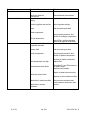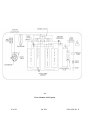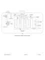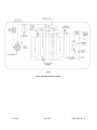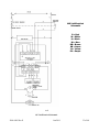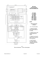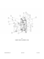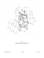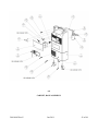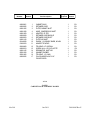
1
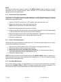
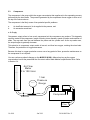
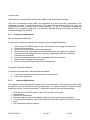
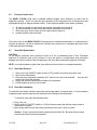
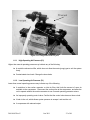
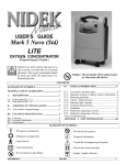
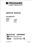
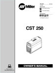
Nidek Medical Products, Inc® Mark 5 Nuvo® Lite Oxygen Concentrator Service Manual Nidek Medical Products, Inc. 3949 Valley East Industrial Drive Birmingham, Alabama 35217 USA Telephone: (205) 856-7200 • 24-Hour Fax: (205) 856-0533 Nidek Medical is a trademark of Nidek Medical Products, Inc. Mark 5 Nuvo® Lite is a registered trademark of Nidek Medical Products, Inc 2010-8405 Rev E Jan 2011 1 of 48 Table of Contents 2 General Safety Instructions Production and Use of Oxygen Use and Maintenance of the Device Standards and Regulations 4 4 5 Home Service Provider Responsibility Important Notice and Symbol Explanations Functional Specifications 6 7 7 Section 1.0 Introduction 1.1 1.2 1.3 Section 2.0 Operational Check and Concentration Test Description of Operation 2.1 Operation Check 2.2 Alarm System 2.3 2.3.1 Power Failure Alarm test Oxygen Concentration Test and Specification 2.4 No Oxygen Flow Alarm test Procedure 2.5 8 8 9 9 9 10 Section 3.0 Patient Instructions 3.1 3.2 General Instructions Routine Maintenance by the Patient 3.2.1 Cleaning the Cabinet Air Filter 3.2.2 Checking the Alarm System Battery 10 11 11 11 Section 4.0 Home Service Provider Maintenance Routine Maintenance 4.1 4.1.1 Cabinet Air Filter 4.1.2 Final Product Filter Replacement 4.1.3 Compressor Inlet Air Filter Replacement 4.1.4 Recording Maintenance 11 11 12 12 12 4.2 Cleaning Unit 4.2.1 Preparing for New Patient Use 13 13 5.1 5.2 Components Cabinet Removal 5.2.1 Removing Cabinet Back 5.2.2 Caster Replacement 13 13 13 13 Section 5.0 Service - 2 of 48 Jan 2011 2010-8405 Rev E 5.3 Compressor 5.3.1 Compressor Replacement 5.3.2 Capacitor Replacement 5.4 5.5 Process Control Valve Sieve Bed Replacement 5.5.1 Sieve Bed Removal 5.5.2 Sieve Bed Installation Cabinet Fan Replacement Circuit Board Replacement 5.7.1 Circuit Board Removal 5.7.2 Circuit Board Installation Product Regulator Check and Setting 5.8.1 Product Regulator Cleaning or Rebuilding Pressure Switch Replacement Circuit Breaker Replacement 5.10.1 Circuit Breaker Removal 5.10.2 Circuit Breaker Installation I/0 (ON/OFF) Power Switch Replacement 5.11.1 I/0 (ON/OFF) Power Switch Removal 5.11.2 I/0 (ON/OFF) Power Switch Installation Buzzer Replacement Hour Meter Replacement Flow Valve Replacement 5.14.1 Flow Valve Removal 5.14.2 Flow Valve Installation Power Cord Replacement 5.6 5.7 5.8 5.9 5.10 5.11 5.12 5.13 5.14 5.15 14 15 15 16 16 16 16 17 17 17 18 18 19 19 19 19 19 20 20 20 20 20 20 20 20 21 Section 6.0 Troubleshooting 6.1 6.2 6.3 6.4 6.5 2010-8405 Rev E Air Pressure Test (P1) 6.1.1 High Air Pressure (P1) 6.1.2 Low Air Pressure (P1) Product Pressure Test (P2) 6.2.1 Low Product Pressure 6.2.2 High Product Pressure General Troubleshooting Troubleshooting Chart Tool Kit and Pressure Test Gauge Jan 2011 21 23 23 24 24 24 25 26 29 3 of 48 Appendices Exploded Drawings A-1: A-2: A-2-A: A-3: A-4: A-5: A-6: A-6-A: A-6-B: A-7: A-7-A: A-8: A-8-A: A-9: A-9-A: A-10: A-10-A: A-11: OCSI Pneumatic Diagram Standard Pneumatic Diagram No-Flow Alarm Pneumatic Diagram 115 Volt Electrical Schematic 230 Volt Electrical Schematic Electrical Schematic for No Flow Board Electrical & Compressor Assembly Electrical & Compressor Assembly Parts Compressor Mounting Bracket Parts Front Cabinet Standard Assembly Front Cabinet Standard Assembly Parts Front Cabinet OCSI Assembly Front Cabinet OCSI Assembly Parts Back Cabinet Assembly Back Cabinet Assembly Parts Module Assembly Module Assembly Parts Maintenance Log 30 31 32 33 34 35 36 37 38 39 40 41 42 43 44 45 46 48 General Safety Instructions Production and use of oxygen Oxygen is not a flammable gas, but accelerates the combustion of materials. To prevent fire risks, the MARK 5 NUVO Lite should be kept away from flames, incandescent sources or sources of heat (including cigarettes) and combustible products such as oil, grease, solvents, aerosols, etc. Do not use in an explosive atmosphere. Prevent oxygen from accumulating on upholstered seats or any other fabric. If the concentrator operates without being administered to a patient, locate it so that the flow of product gas produced is dissipated into the air. Locate the equipment in a free space (filter to the rear and below) which is well ventilated and free of fumes or atmospheric pollution. Use and Maintenance of the Device Use the electric cable provided and check that the voltage of the mains socket used complies with the electrical characteristics of the appliance indicated on the manufacturers plate on the rear of the device. 4 of 48 Jan 2011 2010-8405 Rev E Do not use an extension cord or multiple sockets which can create sparks and therefore pose a fire risk. Use of the MARK 5 NUVO Lite must be restricted solely to oxygen therapy on medical prescription in compliance with the daily rate and duration. Use in other circumstances may represent a hazard to patient health. Do not use in a specifically magnetic environment (MRI, etc.). The MARK 5 NUVO Lite has an audible alarm intended to warn the user of any problems. The user must determine the maximum distance away from the Nuvo based on the on the sound levels in the environment, to ensure that the alarm is always audible. Standards & Regulations In compliance with UL60601-1 [EN60601-1] (para 6.82.b): “The manufacturer, assembler, installer or importer are not considered to be responsible for consequences or the safety, reliability and characteristics of a device unless, ● the assembly, extensions, adjustments modifications or repairs have been performed by persons authorized by the manufacturer, ● the electrical installation of the corresponding premises complies with appropriate regulations and codes, ● the device is used in accordance with the instructions for its use. If the replacement parts used for periodic servicing by an approved technician do not comply with the manufacturer’s specifications, the manufacturer is absolved of all liability in the event of an incident. Do not open the equipment when it is powered on: risk of electrocution. This device complies with the requirements of the FDA Quality System Regulation and EU Directive 93/42/EEC and 2007/47/EC, but its operation may be affected by use in the surrounding area of appliances such as diathermy, high frequency electro-surgical instruments, defibrillators, short wave treatment appliances, cell-phones, CB devices and other portables, microwave ovens, induction hot plates or remote control toys, and more generally, by electromagnetic interference exceeding the levels specified in standard IEC(EN) 60601-1-2:2001. As a regulated medical device, both manufacturers and service providers have certain responsibilities regarding complaints. FDA defines a complaint as any written, electronic or oral communication that alleges deficiencies related to the identity, quality, durability, reliability, safety, effectiveness or performance of a device that has been released for distribution. 2010-8405 Rev E Jan 2011 5 of 48 Service providers have a responsibility to evaluate any complaints received from their direct customers. ( Ref. CFR 820.198 ). Nidek Medical does not have direct links to your customers. Your evaluation should include the following: ● Determine if the complaint warrants action by Nidek Medical, ● If NO, resolve the complaint with your customer, ● If YES, contact Nidek Medical customer service, ● Work with Nidek Medical to resolve all complaints. 1.0 Introduction 1.1 Home Service Provider Responsibility All Home Service Providers of the Nidek Medical MARK 5 NUVO Lite Oxygen Concentrator must assume responsibilities for handling, operational check-out, patient instruction, and maintenance. These responsibilities are outlined below and throughout this manual. WARNING MARK 5 NUVO Lite units must not be used for or with any life-supporting or life sustaining applications. Patients unable to communicate discomfort while using this device may require additional monitoring. Advise patients to immediately notify their Home Service Provider(s) and/or physician(s) in case of an alarm or any discomfort. As a Home Service Provider, you must do all of the following: 6 of 48 ● Inspect the condition of each MARK 5 NUVO Lite unit immediately upon delivery to your business location. Note any sign of damage, external or internal, on the delivery receipt, and report it directly to both the freight company and Nidek Medical Products, Inc. immediately. ● Check the operation of each MARK 5 NUVO Lite before delivery to a patient. Always operate the unit for a reasonable length of time and check that the oxygen concentration level is within specifications as referred to in Section 2.4. Test the power failure alarm as described in Section 2.3 of this manual. ● Deliver MARK 5 NUVO Lite units only to patients authorized by a physician’s prescription. The MARK 5 NUVO Lite must not be used as a life-supporting or life sustaining device. A backup supply of oxygen must be available. ● Instruct patients and patient caregivers how to use the MARK 5 NUVO Lite in conjunction with the Users Manual. ● Instruct patients and patient caregivers to notify their physicians and/or Home Service Providers if they experience any signs of discomfort. ● Instruct each patient and patient caregivers how to perform routine maintenance of the Jan 2011 2010-8405 Rev E cabinet air filter and how to check the alarm system. (Refer to Section3.2.) Be available to service each patient at any time. Maintain the MARK 5 NUVO Lite in accordance with Section 4.0. Repair components and replace parts only as outlined in this manual. Use only Nidek Medical parts for replacement in MARK 5 NUVO Lite Oxygen Concentrators. ● 1.2 Refer to the MARK 5 NUVO Lite Product Warranty if parts replacement is required within the warranty period. Important Notice and Symbol Explanations As you read the manual, pay special attention to the WARNING, CAUTION, and NOTE messages. They identify safety guidelines or other important information as follows: WARNING: CAUTION: NOTE: Describes a hazard or unsafe practice that can result in severe bodily injury or death. Describes a hazard or unsafe practice that can result in minor bodily injury or property damage. Provides information important enough to emphasize or repeat. The following harmonized symbols (pictograms), used for non-English language countries, will be located in the User’s Guide of the MARK 5 NUVO Lite unit: Read the accompanying documents; particularly the User's Guide. Store, ship and use the device in an upright condition. No smoking within five feet of this device, oxygen-carrying tubing, or accessories. Indicates an alarm signal for low oxygen concentration or other problem. Do not use any oil or grease on or near the device 1.3 Functional Specifications Dimensions: 35.6 cm long, 22.9 cm wide, 58.5 cm high [14 in. long, 9 in. wide, 23 in. tall] Weight: 13 kg [30 Ib] depending on sound attenuation package Electrical 115 VAC, 60 Hz, +/- 10% <330 watts(avg) Requirements: 230 VAC, 50 Hz, +/- 10% <300 watts(avg) 230 VAC, 60 Hz, +/- 10% <330 watts(avg) (280 W for 3 l/min unit) Capacity: Max. 5 liters per minute ( 3 l/min for 925/60K ) Accuracy: Flow Valve ±10% indicated flow rate +/- 200 ml whichever is greater as 2010-8405 Rev E Jan 2011 7 of 48 per ISO 8359 Standard Concentration: 2 liters per minute at >90% 5 liters per minute at 90% (+ 6.5 / - 3%) (Based on 21°C [70°F] at sea level) Response Time: Acceptable concentration is normally achieved in about 90 seconds; allow 5 minutes to attain full concentration. Positioning: Operate the unit in an upright position, maintaining at least six inches of open space on all sides for ventilation. 2.0 Operational Check and Concentration Test 2.1 Description of Operation Air enters the MARK 5 NUVO Lite Oxygen Concentrator through an external cabinet air filter. This filtered air enters the compressor via a suction tube and fine filter, which quiets the suction sounds made by the compressor. Pressurized air then exits the compressor and passes through a heat exchanger into a pair of 3-way solenoid valves. The heat exchanger reduces the temperature of the compressed air. Next, the solenoid valve directs the air into one of two sieve beds that contain molecular sieve. The special characteristic property of molecular sieve is that it physically attracts (adsorbs) nitrogen when air passes through this material, thus enabling the production of high purity oxygen. There are two sieve beds or adsorbent columns; while one produces high purity oxygen, the other is purged of the nitrogen it adsorbed (collected) while it was producing oxygen. Each column produces oxygen for approximately five seconds and delivers it to the product storage volume tank integrated into the sieve module. Oxygen exits the product storage tank through a pressure regulator, flow control valve, and final product filter. The flow control valve, controls the flow rate of oxygen delivered to the patient. The MARK 5 NUVO Lite unit delivers up to 95% oxygen concentration at flow rates from 0.125 to 5 l/min. The remaining constituents of the product gas stream are nitrogen and argon, both of which are part of the air we breathe, are inert and are completely safe. 2.2 Operational Check Nidek Medical runs each device through a burn in period and tests every MARK 5 NUVO Lite Oxygen Concentrator thoroughly after manufacture before releasing for shipment. As the home service provider, it is your responsibility to perform the following test to ensure that no damage occurred in shipping or handling. 1. Open and inspect all concentrator cartons upon receipt. Unpack each unit and remove it from its carton. Inspect the unit itself for damage. If the exterior of the carton is damaged, or the unit itself is damaged, note it on the freight bill signed by the driver. 2. Plug in the power cord of the unit, and set the I/0 (ON/OFF) switch to the I (ON) position. Check to see that the following occurs: ● ● The compressor runs, listen for the sound. Exhausted cooling air flows out of the bottom rear of the unit. 8 of 48 Jan 2011 2010-8405 Rev E ● ● ● OPTIONAL for Units Equipped with Oxygen Concentration Status Indicator (OCSI): The OCSI green light remains off until the oxygen concentration reaches 85% ± 3% (82% ± 2% for 50 Hz units) (approximately two minutes). OPTIONAL for Units Equipped with No Oxygen Flow Alarm Board: The No Oxygen Flow board test should be preformed as in Section 2.5 of this manual. After performing the above steps, remove the power cord from the wall outlet. Actuate the I/0 (ON/OFF) switch to the I (ON) position and note that the audible alarm sounds intermittently. (See Section 2.3). If the unit does not initially sound off, plug the unit in and allow the unit to run approximately 10 minutes to charge the capacitor and repeat the test. Move the switch to the 0 (OFF) position. 3. Turn the flow valve adjustment knob clockwise until it stops (wide open). The flow valve should indicate 5 liters/min. and the output of the unit should be 5 liters/min. If not, refer to Section 5.8 to adjust the product regulator. 4 Perform an oxygen concentration test, as described in Section 2.4. 2.3 Alarm System The MARK 5 NUVO© Lite Oxygen Concentrator is equipped with a capacitor powered alarm system, which sounds an intermittent alarm when a power failure occurs and a continuous alarm when one or more cycle variables are not within specification. It sounds an alarm if the high or low pressure indicators are activated or if the optional OCSI detects lower than predetermined levels of oxygen concentration. The alarm remains on until you correct the alarm condition or you set the I/0 (ON/OFF) switch to the 0 (OFF) position. Refer to Section 6.0 for a list of probable alarm causes. 2.3.1 Power Failure Alarm Test To test the power failure alarm, perform the following actions: Unplug the power cord from the wall outlet, and set the I/0 (ON/OFF) switch to the I (ON) position. If the unit has been stored for a prolonged period, Allow unit to run for approximately 10 minutes to charge the capacitor and re-test the unit. This should immediately activate the intermittent audible alarm. If it does not, refer to the troubleshooting chart in Section 6.0 of this manual. 2.4 Oxygen Concentration Test and Specification To ensure that the output of oxygen from the device is within specification, you must perform an oxygen concentration test. Test the unit upon delivery to a patient and at periodic intervals. Home Service Providers, based on their expertise and documentation, may establish and implement their own plans for checking oxygen concentration. Consult Nidek Medical’s Service and Maintenance Log (A-11) for the recommended intervals for testing. 1. If an oxygen humidifier bottle is used, remove it from the oxygen outlet. 2010-8405 Rev E Jan 2011 9 of 48 2. Connect a calibrated oxygen concentration analyzer to the oxygen outlet. 3. Set the I/0 (ON/OFF) power switch to the I (ON) position. (It takes approximately five minutes for the oxygen concentration to stabilize.) Take oxygen concentration readings over a period of several minutes to reduce any cyclic variations 4. Verify that the product flow rate delivered by the unit matches the patient’s prescription and does not exceed the capacity of the unit. 5. Disconnect the oxygen analyzer, and reconnect the humidifier bottle (if used) and any other equipment / accessories that may be required. 6. Adjust the flow valve knob to the prescribed flow rate. Nidek Medical MARK 5 NUVO Lite Concentration Specifications Liter Flow 2 l/min 5 l/min Specification greater than 90% 90% + 6.5 / - 3% NOTE: Do not measure oxygen concentration output after the product stream passes through a humidifier bottle. Erroneous readings will result and your oxygen concentration measuring device might be damaged. 2.5 No Oxygen Flow Alarm Test Procedure A No Oxygen Flow Alarm board is available as an option with the Nuvo Lite Oxygen Concentrator. To test the function of “No Flow” alarm, follow the instructions below: 1. 2. 3. 4. Turn Concentrator on and allow the unit to reach normal operating purity. Adjust the Oxygen Flow to desired flow rate. Block the oxygen flow at the patient outlet A continuous audible alarm should sound as long as the Oxygen flow is blocked 3.0 Patient Instructions 3.1 General Instructions It is important that patients thoroughly understand how to operate the Nidek Medical MARK 5 NUVO Lite unit. This enables proper treatment as prescribed by a qualified, licensed physician. You must explain that the purpose of this therapy is to alleviate symptoms. If patients experience any discomfort or the unit alarms, they must notify their Home Service Provider and/or physician immediately. You, as the Home Service Provider, are responsible to see that each patient receives the User's Guide. Explain each step in the operation of the unit to the patient in reference to that guide. 10 of 48 Jan 2011 2010-8405 Rev E 3.2 Routine Maintenance by the Patient To ensure accurate output and efficient operation of the unit, the patient must perform two simple routine maintenance tasks: • Clean the cabinet air filter • Check the alarm system 3.2.1 Cleaning the Cabinet Air Filter NOTE: The patient must clean this filter weekly, as described below. The filter may require daily cleaning if the MARK 5 NUVO Lite unit operates in a harsh environment such as a house heated by wood, kerosene, or oil, or one with excessive cigarette smoke. 3.2.2 1 Remove the dirty cabinet air filter from the back of the MARK 5 NUVO Lite unit. 2 Wash the dirty filter in warm water with household detergent, and rinse. 3 Use a soft absorbent towel to remove excess water. 4 Reinstall the clean cabinet air filter on the grille in the back of the unit. Be careful that the filter edges are under the tabs. Checking the Power Alarm System See Procedure described in Paragraph 2.3.1 4.0 Home Service Provider Maintenance 4.1 Routine Maintenance The MARK 5 NUVO Lite unit has three filters that require inspection and scheduled maintenance or replacement. To ensure that the output of oxygen from the unit is within specification, you must perform an oxygen concentration test. Test the unit upon delivery to a patient and at periodic intervals. Home Service Providers, based on their expertise and documentation, should establish and implement their own practices for checking oxygen concentration. The interval established may be longer or shorter than 90 days, which is the default time period recommended for providers who do not choose to establish their own method. Nidek Medical does not require preventive maintenance on the concentrator. You do not need to perform any maintenance as long as the MARK 5 NUVO Lite unit remains within specifications at the prescribed flow rate. (Refer to Section 2.4) 4.1.1 Cabinet Air Filter The external cabinet air filter is located on the back of the unit, You can easily remove it by hand. Instruct the patient to clean this filter weekly. (Refer to Section 3.2.1.) 2010-8405 Rev E Jan 2011 11 of 48 NOTE: The filter may require more frequent cleaning if the MARK 5 NUVO Lite unit operates in a harsh environment such as a house heated by wood, kerosene, or oil, or one with excessive cooking, cigarette smoke or atmospheric dust. 4.1.2 Final Product Filter Replacement The final product filter does not require periodic replacement; it needs to be replaced only if it restricts oxygen flow. It is suggested that it be replaced whenever the sieve module is repaired or replaced and after the compressor is rebuilt. 1. Set the I/0 (ON/OFF) switch to the 0 (OFF) position, and unplug the power cord. 2. Remove the cabinet back to locate the final product filter. NOTE: Observe the position of the filter before removal. 3. Separate the silicone tubing from both sides of the filter. 4. Install the new filter with the inlet side in the same position as before. Push the tubing together so that it overlaps the barbs of the final product filter connections. 5. Record information about the final product filter replacement in Appendix 11 of this manual and online at www.nidekmedical.com under the ‘Maintenance Log’ tab. 6. Reinstall the cabinet back. 4.1.3 Inlet Air Filter Replacement The inlet air filter requires inspection at each patient visit. The filter should be replaced every 2 years, or more often depending on environment. 1. 2. 3. 4. Set the unit I/0 (ON/OFF) switch to the 0 (OFF) position, and unplug the power cord. Remove the cabinet air filter to locate the inlet air filter. Remove filter from the unit, and replace with a new filter. Record information about the filter replacement in Appendix 11 of this manual and online at www.nidekmedical.com under the ‘Maintenance Log’ tab. 5. Reinstall the cabinet air filter. NOTE: The filter may require more frequent cleaning if the MARK 5 NUVO Lite unit operates in a harsh environment such as a house heated by wood, kerosene, or oil, or one with excessive cooking, cigarette smoke or atmospheric dust. 4.1.4 Recording Maintenance As the Home Service Provider, it is suggested that you record all routine maintenance and repairs performed on the MARK 5 NUVO Lite unit, including hours and dates of service in Appendix 11 of this manual and online at www.nidekmedical.com under the ‘Maintenance Log’ tab. 12 of 48 Jan 2011 2010-8405 Rev E 4.2 Cleaning Unit Periodically, use a damp cloth to wipe down the exterior case of the MARK 5 NUVO Lite. If you use medical disinfectants, be sure to follow manufacture’s instructions. 4.2.1 Preparing for New Patient Use When you remove the MARK 5 NUVO Lite from a patient’s home, always dispose of the used nasal cannula and humidifier bottle. Inspect the humidifier tube and clean or replace as needed. Replace the cabinet air filter between each patient’s use or clean with warm soapy water if it is in good condition. Clean this filter at least once per week or more frequently if operated in a dusty environment. Retest the MARK 5 NUVO Lite before you return it to your inventory. 5.0 Service 5.1 Components The design of the Nidek Medical MARK 5 NUVO Lite Oxygen Concentrator allows for easy access and removal of most components. This allows you to perform scheduled maintenance, repair, and replacement of parts with minimal time and effort. The inlet air filter is conveniently located behind the cabinet air filter on the cabinet back. CAUTION: For your safety, be sure to set the I/0 (ON/OFF) switch to the 0 (OFF) position and unplug the power cord before you service the MARK 5 NUVO Lite Oxygen Concentrator. NOTE: Record all scheduled maintenance on the Maintenance Log found in Appendix 11. (Refer to Section 4.1.4.) 5.2 Cabinet Removal 5.2.1 Removing Cabinet Back Lay the device on its front to access the cabinet back, remove four screws, two at the top near the handle and two near the bottom of the cabinet. 5.2.2 Caster Replacement The casters are a push in type that does not require a fastener. Lay the device on its back to access the casters from the bottom. Pull them straight out away from the bottom. 2010-8405 Rev E Jan 2011 13 of 48 5.3 Compressor The compressor is the pump within the oxygen concentrator that supplies air to the separation process performed by the sieve beds. The pressure generated by the compressor forces oxygen to flow out of the top of the sieve columns. The compressor is the likely cause of two potential specific problems: a. b. An insufficient amount of air is supplied to the process, and An excessive sound level. ● Air Supply Compressor output refers to how much compressed air the compressor can produce. This depends upon the model of the compressor, length of stroke, piston diameter, speed of rotation and condition of seals. The cup seals form the seal between the piston and the cylinder wall. As the cup seals wear, the output begins to gradually decrease. This reduction in compressor output results in less air, and thus less oxygen, entering the sieve beds. Therefore, the production of oxygen decreases. Because this drop in oxygen production occurs over a long period of time, preventive maintenance on the compressor is not required. You can continue a patient’s therapy on the MARK 5 NUVO Lite unit as long as the oxygen concentration level at the prescribed liter flow rate is within Nidek Medical’s specification limits. Refer to Section 2.4. __ ___ __ __ ___ __ __ ___ __ __ ___ __ __ ___ __ __ ___ __ __ ___ __ __ ___ __ __ ___ __ __ ___ __ __ ___ __ __ ___ __ __ ___ __ __ ___ __ __ ___ __ __ ___ __ __ ___ __ __ ___ __ __ ___ __ __ ___ __ __ ___ __ __ ___ __ __ ___ __ __ ___ __ __ ___ __ __ ___ __ A ir F low M eter 0 to 100 l/m in P ressu re 1 bar P ressure G auge F lo w C om pressor R estrictor A ir F ilter 14 of 48 Jan 2011 2010-8405 Rev E ● Sound Level The sound level is largely determined by the condition of the compressor’s bearings. There are four bearings located within the compressor that allow the inner components of the compressor to rotate. If the bearings wear to the point that they become loose and noisy, the compressor becomes noticeably loud and needs servicing. The life of a compressor is determined primarily by its operating temperature. It is extremely important that the inlet cooling air filters are cleaned and replaced as required. 5.3.1 Compressor Replacement Remove Compressor Assembly To remove the compressor assembly for exchange, follow the steps listed below: 1. 2. 3. 4. 5. 6. 7. 8. Set the unit’s I/0 (ON/OFF) switch to the 0 (OFF) position, and unplug the power cord. Remove the cabinet back. Disconnect the suction tube and the discharge tube. Disconnect the two compressor power cable leads and the two leads to the capacitor. Disconnect the two springs from the compressor support plate. Slide the compressor assembly from the cabinet. Remove compressor springs from the compressor with the two screws. Remove heat exchanger from compressor. Remove the heat exchanger fitting from the compressor. Compressor Assembly Installation To install a new compressor, follow the steps listed below: 1. 2. 5.3.2 Perform the compressor removal procedure in reverse order. Leak test all connections. Capacitor Replacement The capacitor helps the compressor to start and run more efficiently. If the compressor cannot start, the capacitor may be defective and require replacement. The capacitor should be replaced at each compressor service / module replacement. To replace the capacitor, take the following steps: 1. Set the unit’s I/0 (ON/OFF) switch to the 0 (OFF) position, and unplug the power cord. 2. Remove the cabinet back. 3. Disconnect the two leads to the capacitor and clip the tie wrap securing the capacitor. 4. To install the new capacitor, connect the leads and replace the capacitor and install a new tie wrap. 5. Clip excess after securing capacitor. 2010-8405 Rev E Jan 2011 15 of 48 5.4 Process Control Valve The MARK 5 NUVO Lite uses a solenoid powered poppet valve assembly to control the air separation process. There is a feed port that connects to the compressor and an exhaust port that discharges through an integral exhaust muffler. There are three possible valve states as follows: 1. 2. 3. 4. Air feed connected to sieve bed A and exhaust connected to sieve bed B. Air feed connected to sieve bed B and exhaust connected to sieve bed A. Both ports open; this is a very short time period during which air pressure builds in the sieve beds. The control valve of the MARK 5 NUVO Lite requires no scheduled maintenance. If a valve does not function as required, it is best to replace the complete sieve module as it is probable that one or both of the beds has been damaged. 5.5 Sieve Bed Replacement CAUTION: Do not expose molecular sieve (contents of bed) to air for an extended period of time. Prolonged exposure of molecular sieve to the moisture in room air results in contamination and permanent damage to the sieve material. Keep all openings to the sieve beds sealed during periods of storage. NOTE: It is recommended to replace the sieve beds and control valve as a complete assembly. 5.5.1 Sieve Bed Removal 1. Set the unit’s I/0 (ON/OFF) switch to the 0 (OFF) position and unplug the power cord. 2. Remove the cabinet back. 3. Disconnect the compressor discharge 5/16” tube from the top of the solenoid valve and the product tube from the regulator. 4. Unplug the solenoid valve electrical leads at the solenoids. 5. Lift the module up and out of the cradle. 5.5.2 Sieve Bed Installation To install the sieve beds, follow the sieve bed removal procedure in reverse order. It is very important to tighten ensure that the tubes are fully inserted into the fittings to eliminate leaks. To check for leaks, take the following steps: 1. Plug in the unit. 2. Set the unit’s I/0 (ON/OFF) switch to I (ON) for three minutes with the flow meter closed to pressurize the system. 3. Apply soapy water around the tubing connections at the valve; check for leaks. Caution: There is an electrical shock hazard with the Power ON. Be careful that no water contacts any of the electrical connections. 16 of 48 Jan 2011 2010-8405 Rev E NOTE: Even small leaks can affect concentrator performance and can cause contamination of sieve. Careful leak testing is important. 5.6 the Cabinet Fan Replacement The cabinet fan for the MARK 5 NUVO Lite is located adjacent to the compressor. Refer to the troubleshooting chart in Section 6.0 of this manual for instances where replacement of the fan may be required. To replace the cabinet fan in the Mark5 Nuvo® unit, take the following steps: 1. 2. 3. 4. 5. 6. 7. 5.7 Set the unit’s I/0 (ON/OFF) switch to the 0 (OFF) position and unplug the power cord. Remove the back cabinet. Disconnect the fan leads. Lift out the fan. Install isolation foam around new fan. Insert into cabinet and connect the fan leads. Reinstall the back cabinet. Circuit Board Replacement There are two printed circuit boards within the MARK 5 NUVO Lite There is a printed circuit board that controls the alarm system functions and also a printed circuit board that controls the timing logic for the solenoid valves. Consult the troubleshooting chart in Section 6.0 to determine which and when to replace the one of the printed circuit boards. CAUTION: The Printed Circuit Boards (PCB) contain components that are sensitive to electrostatic discharge (ESD) that can damage the board if not handled properly. As when handling any ESD sensitive PCB, observe standard ESD safety procedures. These procedures include the following: • Handle the PCB by the edges only. • Work on a grounded ESD mat. • Wear a grounded wrist strap. • Store PCB in anti-static bags only. 5.7.1 Alarm Circuit Board Removal (Note that the Circuit Board on the OCSI unit is different to the Circuit Board on the standard unit.) 1. 2. 3. 4. Set the I/0 (ON/OFF) switch to the 0 (OFF) position, and unplug the power cord. Remove the cabinet back. Disconnect the 7-pin connector from the upper circuit board. Disconnect tubing from each end of the black sensor tube on the OCSI unit, noting their position and orientation. 2010-8405 Rev E Jan 2011 17 of 48 5. Non OCSI units: Cut tie-wrap and remove pressure sensor line. 6. Remove the screws that attach the board to the front cabinet. 7. Remove the circuit board. NOTE: Handle the new circuit board only by the edges to prevent electrostatic damage to the unit. For Reinstallation reverse the above procedure. 5.7.2 Timing Circuit Board Removal 1. Set the I/0 (ON/OFF) switch to the 0 (OFF) position, and unplug the power cord. 2. Remove the cabinet back. 3. Disconnect the 6 and the 4 pin connectors as well as the 6 spade connectors from the Timing Board. Brown 220V (White 110V) wires towards the module side and Blue 220V (Black 110V) wires toward the compressor side. 4. Remove the mounting screws. 5. Remove the circuit board. NOTE: Handle the new circuit board only by the edges to prevent electrostatic damage to the unit. For Reinstallation reverse the above procedure. 5.7.3 MARK 5 NUVO Lite units produced after 1 June 2010 have a PCB that includes the functions of both the Alarm Circuit board and the Timing Board that were used in earlier units. The new board includes two LED's that are visible inside the unit. They have been added to assist the service technician in determining that the solenoid valves have power to them and are cycling. Also, the new board flashes the green LED during the startup phase to indicate that the device has power. The flashing green LED is continuous when oxygen concentration reaches the specified level. 5.8 Product Regulator Check and Setting The product regulator enables you to set the maximum flow of oxygen output by the MARK 5 NUVO Lite unit. To check for proper adjustment of the product regulator, take the following steps: 1. 2. 3. 4. 5. Set the I/0 (ON/OFF) switch to the I (ON) position. Allow the unit to run for a few minutes. Connect a pressure gauge directly to the patient outlet. The pressure should read 7.1 psig (49 kPa) ± 10%. If it requires adjustment, remove the cabinet back and lift out the module enough to access the regulator. 6. Adjust the regulator as necessary. Turn the knob clockwise to increase the output pressure. (Requires a 3/32 hex wrench) 7. Reinsert the module assembly and reinstall the cabinet back. 18 of 48 Jan 2011 2010-8405 Rev E 5.8.1 Product Regulator Cleaning or Rebuilding Clean or rebuild the product regulator if the regulator cannot be adjusted. I. 2. 3. 4. 5. 6. 7. 8. 9. 10. 11. 12. 13. 5.9 Set the I/0 (ON/OFF) switch to the 0 (OFF) position, and unplug the power cord, Remove the back cabinet. Remove the regulator from the tee on top of the solenoid valve assembly. Adjust the product regulator fully counterclockwise to unload the spring. This makes disassembly and reassembly easier. Remove the diaphragm. (Clean or replace it.) Use a hex-head screwdriver to unscrew the diaphragm stem guide located in the center of the regulator body to gain access to the seat, Remove the seat. Be careful not to lose the spring located behind the seat. Replace the seat or clean by blowing clean air on and around it. With the spring behind the seat, screw the diaphragm stem guide back into the body of the regulator. (Do not over tighten.) Install a clean or replacement diaphragm. Put the large spring and slip ring into the bonnet, and screw the bonnet onto the regulator body. Reinstall the regulator. Reset the product regulator as described in Section 5.8.1. Pressure Monitoring Board Replacement (Standard Unit, Non OCSI only) The high and low pressure alarms are activated by a pressure transducer located on the alarm circuit board adjacent to the mains switch. 1. 2. 3. 4. 5. 6. 5.10 Set the I/0 (ON/OFF) switch to the 0 (OFF) position, and unplug the power cord. Remove the back cabinet. Disconnect the 7 pin connector from the circuit board. Disconnect tubing from pressure sensor by cutting tie-wrap. Remove the circuit board and replace with a new one. Test the alarm system, as described in Section 2.3.Reinstall the back cabinet. Circuit Breaker Replacement 5.10.1 Circuit Breaker Removal 1. 2. 3. 4. Set the I/0 (ON/OFF) switch to the 0 (OFF) position, and unplug the power cord. Remove the cabinet back. Disconnect the circuit breaker leads. Unscrew the circuit breaker while you apply pressure to the circuit breaker retaining ring. 5.10.2 Circuit Breaker Installation Follow the removal procedure for the circuit breaker in reverse order to install the new circuit breaker. 2010-8405 Rev E Jan 2011 19 of 48 5.11 I/0 (ON/OFF) Power Switch Replacement 5.11.1 I/0 (ON/OFF) Power Switch Removal 1. Set the I/0 (ON/OFF) switch to the 0 (OFF) position and unplug the power cord. 2. Remove both the back cabinet. 3. Disconnect the I/0 (ON/OFF) switch leads from the back of the switch being careful to note the position of each. 4. Push on the back of the power switch, while holding in its four retaining tabs, and remove the switch through the front of the control panel. 5.11.2 I/0 (ON/OFF) Power Switch Installation Follow the removal procedure for the I/0 (ON/OFF) power switch in reverse order to install a new power switch. 5.12 Buzzer Replacement The buzzer is a fixed component on the circuit board and is not individually replaceable. 5.13 Hour Meter Replacement 1. 2. 3. 4. 5. Set the I/0 (ON/OFF) switch to the 0 (OFF) position, and unplug the power cord. Remove the cabinet back. Disconnect the hour meter leads. Remove the hour meter from the front cabinet. Install the new hour meter into its mounting location. Make sure that the hour meter is mounted right side up. 6. Reconnect the hour meter leads. 7. Reinstall the cabinet back. 5.14 Flow Valve Replacement 5.14.1 Flow Valve Removal 1. 2. 3. 4. 5. Set the I/0 (ON/OFF) switch to the 0 (OFF) position, and unplug the power cord. Remove the cabinet back. Remove the two hoses from the back of the flow valve. Remove the knob from the flow valve, and the two Philips screws below the knob. Remove the flow valve. 5.14.2 Flow Valve Installation To install a new flow valve, follow the flow valve removal procedure in reverse order. Then perform a leak test on the connections. 20 of 48 Jan 2011 2010-8405 Rev E 5.15 Power Cord Replacement 1. Set the I/0 (ON/OFF) switch to the 0 (OFF) position and unplug the power cord. 2. Remove the cabinet back. Clip the power cord retaining tie wrap 3. Slide the power cord strain relief reinforcement upwards to remove it from the mounting location at the bottom of the front cabinet. 4. Disconnect the power cord leads from the terminal quick connects. 5. Connect the leads on the new power cord at the terminal quick connects. 6. Reinstall the power cord strain relief into the base of the unit. 7. Reconnect the cabinet back and install a new power cord retaining tie wrap. 6.0 Troubleshooting 6.1 Air Pressure Test (P1) Testing the operating pressure is a useful diagnostic tool when a concentrator has low purity and requires servicing. Units functioning normally do not require operating tests. Use the following procedure to test the operating pressure of the unit. 1. Set the I/0 (ON/OFF) switch to the 0 (OFF) position, and unplug the power cord. 2. Remove the cabinet rear. 3. Remove the air supply tubing going to the control valve and install the test port tee fitting. Figure 6.1.1 & 6.1.2 shows the normal operating configurations for each type of unit. Figure 6.1.3 shows the installation of the test ports. 4. Connect the pressure test gauge to the test port. 5. Plug in the power cord, and set the I/0 (ON/OFF) power switch to the ON position. Set the flow meter to 5 l/min, and allow the unit to run at least five minutes. 6. Observe the maximum and minimum readings on the pressure test gauge. 7. The maximum reading should not exceed 34 psig (235 kPa). The minimum reading should not be less than 10 psig (70 kPa). NOTE When you turn the unit on, it will take several minutes to reach normal operating pressures. 2010-8405 Rev E Jan 2011 21 of 48 Figure 6.1.1 normal operating configuration (OCSI unit). Figure 6.1.2 normal operating configuration (standard unit). 22 of 48 Jan 2011 2010-8405 Rev E Figure 6.1.3 configuration with test ports 6.1.1 High Operating Air Pressure (P1) Higher than normal operating pressure may indicate any of the following: ► A restrictive exhaust muffler, which does not allow the waste (purge) gas to exit the system freely. ► Contaminated sieve beds. Change the sieve beds. 6.1.2 Low Operating Air Pressure (P1) Lower than normal operating pressure may indicate any of the following: ► A restriction in the suction resonator or inlet air filter, this limits the amount of room air available to the compressor. Disconnect the suction tube at the compressor, and allow the unit to operate without the suction resonator to see if normal operating pressure returns. ► An improperly operating control valve. Confirm that the control valve does not have a leak. ► A leak in the unit, which allows system pressure to escape. Leak test the unit. ► A compressor with reduced output. 2010-8405 Rev E Jan 2011 23 of 48 Ensure that the concentration level at the desired liter flow is within specifications listed in section 2.4. If it is below specifications, replace or repair the compressor. 6.2 Product Pressure Test (P2) Testing the product pressure is a useful diagnostic tool when a concentrator has low purity and requires servicing. Units functioning normally do not require operating tests. Use the following procedure to test the product pressure of the unit. 1. Set the I/0 (ON/OFF) switch to the 0 (OFF) position, and unplug the power cord. 2. Remove the cabinet rear. Remove the cap from the regulator test port and install the test port tee. Figure 6.1.1 & 3. Remove the cap from the regulator test port and install the test port tee. Figure 6.1.1 & 6.1.2 shows the normal operating configurations for each type of unit. Figure 6.1.3 shows the installation of the test ports. 4. Connect the pressure test gauge to the P2 test port. 5. Plug in the power cord, and set the I/0 (ON/OFF) power switch to the ON position. Set the flow meter to 5 l/min, and allow the unit to run at least five minutes. 6. Observe the maximum and minimum readings on the pressure test gauge. The maximum reading should not exceed 32 psig (220kPa). The minimum reading should not be less than 9 psig (62 kPa). 6.2.1 Low Product Pressure (P2) Lower than normal operating pressure may indicate any of the following: ► An inlet air filter that limits the amount of room air available to the compressor. Disconnect the suction tube at the compressor, and allow the unit to operate without the suction resonator to see if normal operating pressure returns. ► An improperly operating control valve. Confirm that the control valve does not have a leak. ► A leak in the unit, which allows system pressure to escape. Leak test the unit. ► A compressor with reduced output. Ensure that the concentration level at the desired liter flow is within specifications listed in Section 2.4. If it is below specification, replace or repair the compressor. 6.2.2 High Product Pressure (P2) Higher than normal operating pressure may indicate any of the following: ► A restrictive exhaust muffler, which does not allow the waste (purge) gas to exit the system freely. ► Check exhaust muffler for any restrictions ► Contaminated sieve beds. Change the sieve beds. 24 of 48 Jan 2011 2010-8405 Rev E 6.3 General Troubleshooting Before reviewing the troubleshooting chart, the following steps may be useful to isolate any malfunctions: 1. Turn the concentrator on. If unit does not turn on, refer to troubleshooting chart. 2. Make sure all filters are clean. 3. Connect test pressure gauge to the outlet fitting of the unit. The pressure should read 7.1 psig (49 kPa) ± 10%. 4. Connect test pressure gauge to the P1 test port on the module. The pressure should be cycling between approximately 10 and 34 psig (70 and 235 kPa). 5. Make sure the unit is cycling properly by observing the pressure gauge cycle between a high and a low pressure. If the unit is not cycling properly, refer to troubleshooting chart. 6. Make sure that the unit is leak free by testing all tubing connections and fittings with leak testing solution. Protect circuit board from solution and start leak test at the heat exchanger, following the air flow through the unit to the oxygen outlet. Repair all leaks by tightening connections and fittings. 7. Set the concentrator at 5 l/min and connect pressure test gauge to P2 at the top of the sieve beds. Determine pressure parameters by observing high and low pressure points on the gauge. It should cycle between approximately 9 psig and 32 psig (62 to 220 kPa). If pressures are high or low, refer to the troubleshooting chart. 8. Review troubleshooting chart to isolate and repair any other malfunctions. The following diagnostic flow chart will help to isolate potential problems. 2010-8405 Rev E Jan 2011 25 of 48 Low Oxygen Concentration Verify O xygen Flow R ate M easure Air Pressure Low Pressure H igh Pressure R eplace Air Inlet Filter Replace M uffler Foam s C heck for Leaks Check C ontrol Valve C heck the C om pressor N orm al Air Pressure M easure the O xygen Pressure Low Pressure H igh Pressure C heck for Leaks Replace Muffler Foams C heck the C ontrol Valve Replace Sieve M odule N orm al Pressure Check for leaks at the: - regulator outlet - product tubing - oxygen outlet 26 of 48 Jan 2011 2010-8405 Rev E Problem Compressor runs with intermittent high pressure alarm and low oxygen concentration. Probable Cause Defective sieve beds. Solution Replace sieve beds. Restriction in exhaust muffler. Replace or clean muffler. Defective valve. Compressor relief valve releases (popping sound). Defective control valve. Replace sieve module. Replace sieve module. Contaminated sieve beds. Replace sieve module. Defective relief valve. Replace sieve module. Replace relief valve. Constant alarm with I/0 (ON/OFF) switch in ON position. Circuit breaker repeatedly trips. Defective circuit breaker. Replace circuit breaker. Defective capacitor. Replace capacitor. Defective compressor. Replace compressor. Defective circuit board. Replace circuit board. Faulty electrical connection. Repair electrical connection. Alarm does not sound. Faulty electrical connection. Repair electrical connection. Defective I/0 (ON/OFF) switch. Replace I/0 (ON/OFF) switch. Defective buzzer. Replace board. Defective pressure sensor. Flow fluctuates. Improperly set or faulty product regulator. Replace and test control board. Check regulator setting/clean, repair, or replace regulator. Leak test. Leak. Replace compressor Worn compressor. Replace flow valve. Defective flow valve. Kinked tubing 2010-8405 Rev E Check tubing that connects the top of the sieve beds. Jan 2011 27 of 48 Problem Cabinet fan does not turn. Limited or Iow flow. Probable Cause Defective cabinet fan. Solution Replace cabinet fan. Defective electrical connections. Restriction in humidifier or tubing. Check electrical connections. Product regulator set too low. Adjust regulator setting. Leak. Leak test and repair leak. Replace humidifier or tubing. Weak compressor. Check system pressure, and rebuild or exchange compressor. Air flow obstruction. Low concentration. Compressor inlet filter is dirty or partially blocked. Check Filter, suction resonator, and suction tube for obstruction. Replace inlet filter. System leak Leak test and repair leak. Faulty compressor Check system pressure, and rebuild or replace compressor. Unit temperature too high, Contaminated sieve beds. Blocked air intake or defective cabinet filter. Check that P1 and P2 pressures are within range. Replace sieve module. Repair or replace sieve module. Defective control valve. Replace or clean exhaust muffler. Restriction in exhaust muffler, Restriction in suction resonator. 28 of 48 Jan 2011 Check suction resonator and suction tube for obstruction and remove. 2010-8405 Rev E 6.5 Tool Kit, Oxygen Purity testing and Pressure Test Gauge The tools needed for you to properly service the MARK 5 NUVO Lite unit are listed below: ► Requires no special tools; generally available tools including common pliers, channel lock, wire cutters, needle-nose pliers, slotted-head screwdriver, long Phillips head screwdriver, 8inch adjustable wrench, 7/16-inch socket, 7/16-inch combination wrench, 5/8-inch combination wrench and 3/8-inch combination wrench. ► For checking the Oxygen purity at the Concentrator. Nidek Medical recommends Part # 6500-4220 ► An accurate pressure test gauge to take both P-1 and P-2 pressure readings on the MARK 5 NUVO Lite unit should be kept available at all times. This gauge kit allows connections to the pressure test locations. Kit for testing P1 & P2 pressures with gauge supplied # 6500-0051 Kit for testing P1 & P2 pressures w/o gauge supplied # 6500-0052 Kit tools for Nuvo Lite # 6500-0053 Appendices Drawings A-1: A-2: A-2-A: A-3: A-4: A-5: A-6: A-7: A-8: A-9: A-10: OCSI Pneumatic Diagram Standard Pneumatic Diagram No-Flow Alarm Pneumatic Diagram 115 Volt Electrical Schematic 230 Volt Electrical Schematic Electrical Schematic for No Flow Board Electrical & Compressor Assembly Front Cabinet Standard Assembly Front Cabinet OCSI Assembly Back Cabinet Assembly Module Assembly 2010-8405 Rev E 30 31 32 33 34 35 36 39 41 43 45 Jan 2011 29 of 48 A-1 Flow Schematic OCSI Option 30 of 48 Jan 2011 2010-8405 Rev E A-2 Flow Schematic Standard Non-OCSI Option 2010-8405 Rev E Jan 2011 31 of 48 A-2-A Flow Schematic No-Flow Option 32 of 48 Jan 2011 2010-8405 Rev E 115 Volt Electrical Schematic R = Red W = White K = Black BL = Blue BR = Brown GR = Green YL = Yellow PU = Purple A-3 115 Volt Electrical Schematic 2010-8405 Rev E Jan 2011 33 of 48 230 Volt Electrical Schematic R = Red W = White K = Black BL = Blue BR = Brown GR = Green YL = Yellow PU = Purple A-4 230 Volt Electrical Schematic 34 of 48 Jan 2011 2010-8405 Rev E 230 Volt No Flow Option Electrical Schematic. R = Red W = White K = Black BL = Blue BR = Brown GR = Green YL = Yellow PU = Purple NOTE: 230 Volt Version is Shown For 115 Volt Version: 1. SUBSTITUTE BK FOR WHEREVER BL IS USED 2. SUBSTITUE W FOR WHEREVER BR IS USED 3. SUBSTITUTE DPST SWITCH IN PLACE OF TPST SWITCH 4. USE TWO BK VOLTAGE SELECT JUMPERS INSTEAD OF ONE BR A-5 Electrical Schematic – No Flow Alarm Option 2010-8405 Rev E Jan 2011 35 of 48 A-6 ELECTRICAL & COMPRESSOR ASSEMBLY 36 of 48 Jan 2011 2010-8405 Rev E 400-1513 8400-5018 9250-1170 8400-1012 1 2 2 3 SHUNT, VOLTAGE SELECTION HOURMETER AC 100-230 V 50/60 HOURMETER,UNV W/O CLIP SCREW, 8-32 x 5/8"LG.HEX HEAD 1 1 1 2 EA EA EA EA 8400-1010 8400-1049 8400-1052 8400-1053 8400-1016 8400-1094 8400-1095 4 5 6 6 7 8 8 BRACKET,COMPRESSOR BRACKET, HEAT EXCHANGER FITTING,COMPRESSOR FITTING,COMPRESSOR SPRING, EXTENSION EXCHANGER,HEAT EXCHANGER,HEAT 1 1 1 1 2 1 1 EA EA EA EA EA EA EA 8400-1161 8400-1162 8400-1163 8400-1030 8400-1013 9250-1062 9 9 10 12 13 14 TUBING,5/16ODx3/16IDx12.5"LG. TUBING, 5/16ODx3/16IDx9.75"LG. FITTING HX GROMMET,.75"IDX1.0"HOLE RETAINER, SPRING TIE-WRAP, 14" LONG 1 1 1 2 1 2 EA EA EA EA EA EA 8400-1510 8400-1500 8400-1512 9250-1330 9250-1311 8400-1018 15 15 15 16 16* 17 WIRING, HARNESS 230 VOLT WIRING,HARNESS 115 VOLT WIRING,HARNESS UNIVERSAL VOLT CORD, POWER, EUROPLUG CORD,POWER, TYPE "K" PLUG BREAKER,CIRCUIT 10 AMP 115 V 1 1 1 1 1 1 EA EA EA EA EA EA 8400-1019 8400-1008 9250-1012 9250-1023 9250-1024 8400-1042 17 18 18 19 19 20 BREAKER, CIRCUIT 5 AMP 230 V SWITCH,POWER UNIVERSAL SWITCH,POWER 110 VOLT FAN,115V LOW NOISE FAN, 230V LOW NOISE CAPACITOR,20μF P2 1 1 1 1 1 1 EA EA EA EA EA EA 8400-2450 8400-2460 8400-2466 8400-0010 8400-1014 8400-1011 21 21 21 22 23 24 COMPR. 2450 115V/60HZ 5LPM COMPR. 2450 230V/50HZ 5LPM COMPR. 2450 230V/60HZ 3LPM BAFFLE, COMPRESSOR COOLING WASHER SPLIT RETAINING LIMITER COMPRESSOR 1 1 1 1 2 1 EA EA EA EA EA EA 8400-1009 8400-1017 8400-1041 8400-8450 25 26 27 99 CAP, VINYL 3-16" GROMMET, SPRING EYE FAN ISOLATOR KIT, COMP. PLATE ASSY 2 4 2 1 EA EA EA EA ELECTRICAL AND COMPRESSOR ASSEMBLY PARTS A-6-A 2010-8405 Rev E Jan 2011 37 of 48 Part Reference Call-Out Number Number Part Description Qty Unit of Required Measure 8400-1010 1 BRACKET,COMPRESSOR 1 EA 8400-1013 2 RETAINER, SPRING 1 EA 8400-1016 3 SPRING, EXTENSION 2 EA 8400-1030 4 GROMMET,.75"IDX1.0"HOLE 2 EA 8400-1009 5 CAP, VINYL 3-16" 2 EA 8400-1017 6 GROMMET, SPRING EYE 4 EA COMPRESSOR MOUNTING BRACKET PARTS A -6-B 38 of 48 Jan 2011 2010-8405 Rev E A-7 A-7 CABINET, FRONT ASSEMBLY (STD) 2010-8405 Rev E Jan 2011 39 of 48 Part Reference Call-Out Number Number 8400-0002 9251-1330 8400-1331 9251-1332 9251-1335 8400-1020 8400-1024 8400-1022 7631-1053 6956-9674 8400-1102 7854-6051 6491-1006 7854-6052 7854-6055 9250-1041 8400-1337 8400-1204 9250-1045 9251-1336 1 4 5 6 7 8 9 10 11 12 13 14 15 16 17 18 19 20 21 23 Part Description CABINET,FRONT VALVE, FCV 1/8-5.0 LPM KNOB,FLOW 0.125 TO 5.0 FLOW RING,LOCK-OUT CLIP,D STYLE FITTING, OXYGEN OUTLET WASHER, 3/8 STAR O2 OUTLET LITE NUT 3/8-24 O2 OUTLET LITE FILTER, FINAL PRODUCT VALVE, CHECK 1/4 HOSE MPC A975 FOAM, ANTI VIBRATION HOSE 5/32 X 11/32 X 3 LG SILIC ADAPTER 1/4 ODT X 3/16 HOSE HOSE 5/32 X 11/32 X 2 LG SILIC HOSE 5/32 X 11/32 X 7"LG SIL HOSE 5/32 X 11/32 X 5 LONG SIL HOSE 1/8" ID X 1/4" OD 3" LG BOARD,TIMING OMS 9V 5LPM SCREW,PLASTITE#4X3/8" PAN.HD SCREW #6 X32 X.5"LG. FLUSH Qty Unit of Required Measure 1 1 1 1 1 1 1 1 1 1 1 1 1 2 1 1 1 1 8 2 EA EA EA EA EA EA EA EA EA EA EA EA EA EA EA EA EA EA EA EA A-7-A PARTS CABINET, FRONT ASSEMBLY (STD) 40 of 48 Jan 2011 2010-8405 Rev E A-8 CABINET, FRONT ASSEMBLY OCSI 2010-8405 Rev E Jan 2011 41 of 48 Part Reference Call-Out Number Number 8400-0002 9251-1330 8400-1331 9251-1332 9251-1335 8400-1020 8400-1024 8400-1022 7631-1053 6956-9674 8400-1102 7854-6051 6491-1006 7854-6052 7854-6055 9250-1041 8400-1337 8400-1204 9250-1045 9251-1336 1 4 5 6 7 8 9 10 11 12 13 14 15 16 17 18 19 20 21 23 Part Description Qty Unit of Required Measure CABINET,FRONT VALVE, FCV 1/8-5.0 LPM KNOB,FLOW 0.125 TO 5.0 FLOW RING,LOCK-OUT CLIP,D STYLE FITTING, OXYGEN OUTLET WASHER,3/8 STAR O2 OUTLET LITE NUT 3/8-24 O2 OUTLET LITE FILTER, FINAL PRODUCT VALVE, CHECK 1/4 HOSE MPC A975 FOAM, ANTI VIBRATION HOSE 5/32 X 11/32 X 3 LG SILIC ADAPTER 1/4 ODT X 3/16 HOSE HOSE 5/32 X 11/32 X 2 LG SILIC HOSE 5/32 X 11/32 X 7"LG SIL HOSE 5/32 X 11/32 X 5 LONG SIL HOSE 1/8" ID X 1/4" OD 3" LG BOARD,TIMING OMS 9V 5LPM SCREW,PLASTITE#4X3/8" PAN.HD SCREW #6 X32 X.5"LG. FLUSH 1 1 1 1 1 1 1 1 1 1 1 1 1 2 1 1 1 1 8 2 EA EA EA EA EA EA EA EA EA EA EA EA EA EA EA EA EA EA EA EA A-8-A PARTS FRONT CABINET ASSEMBLY OCSI MODEL 42 of 48 Jan 2011 2010-8405 Rev E A-9 CABINET, BACK ASSEMBLY 2010-8405 Rev E Jan 2011 43 of 48 Part Reference Call-Out Number Number 8400-0001 8400-0022 8400-1025 8400-1028 8400-1059 8400-0029 8400-0023 8400-1180 6814-9228 5190-2233 9030-6008 8400-0013 8400-1185 9250-1030 9250-1062 8400-0032 Part Description 1 2 3 4 6 7 8 9 10 11 12 13 14 15 16 17 Qty Unit of Required Measure CABINET,BACK RETAINER,CORD FILTER,CABINET INLET HOSE, COMPRESSOR INLET. ADAPTER, FILTER RETAINER,CORD BUCKLE RETAINER,CORD RIVET FILTER AIR INLET. ELBOW, 1/2 DOUBLE BARB, NYLON HOLDER TIE WRAP TIE-WRAP 4.5" OVERALL SCREW, #14x 1-5"LG PLASTITE RESONATOR, INLET AIR GOMMET,RUBBER TIE-WRAP, 14" LONG PLUG BUNGEE HOLE 3/16" POWER CORD 1 1 1 1 1 1 3 1 1 1 1 4 1 1 1 1 EA EA EA EA EA EA EA EA EA EA EA EA EA EA EA EA A-9-A PARTS CABINET BACK ASSEMBLY MODEL 44 of 48 Jan 2011 2010-8405 Rev E A-10 MODULE NEW ASSEMBLY 5LPM 2010-8405 Rev E Jan 2011 45 of 48 Part Reference Call-Out Number Number 8400-1060 8400-1165 8400-1200 8400-1236 8400-1253 8644-9401 1 2 3 28 29 30 Part Description Qty Unit of Required Measure REGULATOR, 2-PORT FITTING VALVE 5/16"X3/8 VALVE ASSY TEE,ADAPTER NYLON O-RING, REGULATOR TEE -204 PLUG, 1/4~ ODT PUSH IN 1 1 1 1 1 1 EA EA EA EA EA EA A-10-A MODULE ASSEMBLY REPLACEMENT PARTS 46 of 48 Jan 2011 2010-8405 Rev E Nidek Medical Oxygen Concentrator Service and Maintenance Log Model Number ________________ Serial Number ___________________ Initial Inspection Between-Patient Maintenance 1. Upon receipt, check the unit for shipping damage. Notify shipping company if damaged. 2. Verify that cabinet air filter and the inlet air filter are in place. 3. Plug the unit into an electrical outlet, turn the unit 'ON,’ and check the audible/visual alarms. 4. Set the flow meter/flow control at the maximum recommended flow rate and allow the unit to run for 15 minutes. 5. Using a calibrated oxygen analyzer, verify concentration is greater than 87 percent. 1. Remove oxygen tubing, cannula, and humidifier bottle and discard. 2. Wash or replace the humidifier tubing if used. 3. Wash or replace the cabinet air filter. 4. Clean the concentrator cabinet. 5. Check oxygen concentration and flow. If the unit performs within specification, the final product filter does not need to be replaced between patients. Routine Service Check Perform routine servicing as shown in the chart below. Record the activities performed in the log provided on the following page. 1. Record the elapsed usage time in hours. 2. Check oxygen concentration with a calibrated oxygen analyzer. 3. Verify audible alarm and indicator light functions between patients and every two years. 4. Inspect filters and replace as necessary. Patient/Caregiver Maintenance 1. Inspect the Oxygen tubing, cannula, and humidifier bottle - clean as needed according to manufacturer’s instructions. 2. Wash the cabinet air filter weekly with a mild detergent solution. Dry before reinstalling onto the device. The routine service intervals shown below depend on the conditions in which the devices are used. They reflect the minimum recommendation when operated in a clean environment. As conditions can vary widely, the homecare provider or patient caregiver is responsible to determine: - the character of the environment in which the concentrator is to operate. - a maintenance schedule with intervals based on the environment in which the unit is operating/functioning. Standard Servicing Intervals are shown below. Intervals used by the homecare service provider and/or patient caregiver should be more frequent when conditions of usage dictate. Nidek Medical Oxygen Concentrator Routine Service Intervals Check Percent Oxygen Concentration OCSI Models: Every 15,000 hours or 3 years. Std Models: Every 5,000 hours or 1 year. Cabinet Air Filter Inlet Air Filter Final Product Filter Capacitor Wash the filter each week in a mild detergent solution. Dry before reinstalling. Inspect at each patient visit. Replace every 2 years, or more often depending on environment. Replace at each compressor service / module replacement. Replace at each compressor service / module replacement. Please maintain a log of all maintenance activities performed on this unit. Alarms Check Inspection Prior to Putting Into Service Date Hours % O2 Serial Number______________Model_____________ Additional Information (Work Done, Filter Changes, Comments, etc) In-Service Checks Medical device regulations require users and service personnel to notify manufacturers of any incidents that, if repeated, could cause injury to any person. email: [email protected] Please update maintenance log information upon each service at www.nidekmedical.com under the 'Maintenance Log' tab.