1
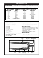
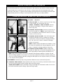
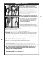
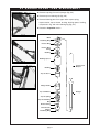
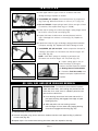
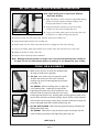
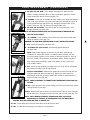
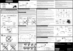
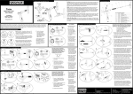
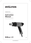
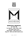
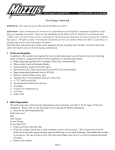
SERVICE MANUAL
ROCK SHOX
1996 Quadra 5 and Quadra 21R
1995 Quadra 5, Quadra 21 and
Quadra 21R;
1994 Quadra 10 and Quadra 21;
1993 Quadra
SUSPENSION FORKS
RockShox, Inc.
1.800.677. 7177
INTRODUCTION
ROCK SHOX QUADRA – To service Quadra forks, you must determine which year and model of Quadra you
are servicing. Please refer to the chart below for assistance in identifying the fork you are working on.
Q U A D R A I D E N T I F I C AT I O N G U I D E
MODEL / YEAR
CROWN
’93 Quadra
’94 Q10
’94 Q21
’95 Q5
’95 Q21
’95 Q21R
’96 Q5
’96 Q21R
BLK,PRESSED ON
PRESSED ON
CLAMP ON
PRESSED ON
PRESSED ON
CLAMP ON
PRESSED ON
PRESS ON (OE), CLAMP ON (DI)
PRELOAD
ADJUSTER
HEX KEY
HEX KEY
HAND ADJUST
HEX KEY
HAND ADJUST
HAND ADJUST
HAND ADJUST
HAND ADJUST
FORK BRACE
BLACK ALUM
BLACK ALUM
BLACK ALUM
STAMPED STEEL/BLK ALUM
GRAY ALUM
YELLOW MAG
BLACK ALUM
YELLOW ALUM
REQUIRED TOOLS
COMMON HAND TOOLS:
• Small tip internal snap ring pliers
• Small tip external snap ring pliers
• 4 mm hex key
• 5 mm hex key
• 8 mm hex key
• 8 mm open end wrench
• Soft face mallet
• Precision calipers, 6"
• Safety glasses
• 3/8" socket drive extension (6" long, minimum)
• 5mm long hex 3/8" drive socket
• 3/8" drive ratchet
• Small flat-blade screwdriver
• 3/8" drive torque wrench
• 22mm socket (3/8" drive) or open end wrench
ROCK SHOX TOOLS:
• Quadra 5/10/21 bushing removal tool (p.n. 70106)
• Quadra 5/10/21 bushing installer tool (p.n. 70108)
• Upper tube clamping blocks (p.n. 70101)
• Seal puller (p.n. 70113)
• Quadra friction ring installer (p.n. 70113)
MISCELLANEOUS:
• High quality bearing grease (JUDY Butter, etc.)
NOTE: DO NOT USE LITHIUM-BASED GREASE.
FORK COMPONENT OVERVIEW
Fork
Brace Bolt
Lower
Tube
Brake
Pivot Bolt
Upper Tube
(covered by
mud boots)
page 1
Fork Brace
Fork
Crown
Damper Adjuster
Screw
Steerer
Tube
M A I N T E N A N C E I N T E R VA L S
1. ROCK SHOX Quadra forks require routine maintenance. After each ride, wipe down the outside of the fork.
2. Approximately once a month and/or every 40 hours of riding, inspect the fork for damage (crown, brace,
upper tubes, lower tubes). 3. A general service (cleaning, greasing elastomers and bushings) should be made
at approximately 200 hours of riding or more frequently if you ride in dusty or muddy conditions.
COMPRESSION BUMPER MAINTENANCE
’93 Quadra — skip to #2
1. ’95 Q5 and Q10: Pr y off dust cap from top cap using
a small straight slot screwdriver (Fig. 2A).
’94 Q21, ’95 Q21(DI), ’96 Q5 and Q21R: Remove
top cap by unscrewing it, using a 22mm socket or
wrench (Fig. 2B).
Fig. 2A
Fig. 2B
2. ’93 Quadra, ’95 Q5 and Q10: Remove top cap using an
8 mm hex key (Fig. 2C). NOTE: It may be necessary to
turn 4 mm adjuster screw clockwise a few turns to permit
insertion of 8 mm hex key.
3. ’93 Quadra, Q5, Q10 and Q21: Clean and inspect each
compression bumper column for evidence of cracking
or permanent set (Fig. 2D). Minimum length (permanent
set) 5.8" (147 mm). If there is evidence of damage,
replace as necessary.
Q21R: Pull MCU springs and spacers from skewers or Judy
Jax. Clean off old grease with a rag and degreaser such as
Pedros. If evidence of damage, replace as necessary.
Fig. 2C
Fig. 2D
4. ’93 Quadra, Q5, Q10 and Q21: Replace compression
bumper into upper tube. It should first be greased all over
with a high quality non-lithium grease (Judy Butter, etc.).
Q21R: Apply a dab of grease to the hole on each MCU spring during installation on skewer. This will
ensure a coating of grease on the skewer. It is necessary to grease the outside of the MCU springs. Be
sure to use a washer between each MCU spring (the solid spacers do not require a washer) if on skewer,
or use Judy Jax and Judy Spacer.
5. ALL MODELS: Reinstall top cap, turning clockwise. Maximum torque is 60 IN–LBS (6.8 Nm).
6. ’93 Quadra, ’95 Q5 and Q10: Adjust preload screw using a 4 mm hex key to desired number of turns
from full counter-clockwise (softest setting). Adjust both legs equally.
’96 Q5, Q21 and Q21R: Adjust preload by turning top cap adjuster the desired number of turns from
full counter clockwise (softest setting). Adjust both legs equally.
page 2
GENERAL SERVICE
INTRODUCTION: The high quality bushings are designed to
last many months of hard riding. The protective boots, a
clean fork, and timely greasing are the keys to long bushing
life. However, like all moving parts, bushings will eventually
wear and need replacement. Increased fore and aft
movement of upper tubes in lower tubes (similar to a loose
headset), slow action even after applying fresh grease,
visible scratches, and worn coating on bushing surface all
signal the bushings need replacing.
Fig. 3A
Fig. 3B
WARNING: THE PROTECTIVE BOOTS ARE PART OF
THE SYSTEM—REMOVING BOOTS VOIDS WARRANTY.
1. Cycle fork several times. Note amount of play detected
fore and aft, and smoothness of stroke. Excessive
fore and aft movement and sticky action could mean
the bushings need replacement.
2. Clean exterior of fork legs. Use soap and water if necessary.
3. Disconnect front brake cable and remove front wheel.
Remove brakes according to manufacturer’s instructions.
Fig. 3C
Fig. 3D
4. Remove brake pivot bolts using an 8 mm wrench (Fig. 3A).
5. Remove fork brace screws using a 4 mm hex key.
6. Remove fork brace from lower tubes.
7. Remove compression bumper. Refer to Compression Bumper Maintenance.
8. ’93 QUADRA: Slide up fork boots to expose lower tube retaining ring. Hold fork boot up and release
retaining ring from lower tube (use internal snap ring pliers (Fig. 3B). Once retaining ring has been
released, pull lower tube off upper tube crown/steerer assembly. Compress leg and then pull down
sharply on lower tube (Fig. 3C). If lower tube does not easily release from assembly, spray WD-40 (or
another thin lubricant) into assembly, then warm lower tube with a heatgun (hairdryer).
!
▲
NOTE: ’93 Quadra: Main retaining ring holds fork together.
WARNING!! DO NOT USE OPEN FLAME ON MAGNESIUM LOWER LEGS.
Q5, Q10, Q21 and Q21R: Be sure legs are compressed and use a long 5mm hex on a long
extension to unscrew and remove plunger assembly from lower tube (Fig. 3D). The lower tube can now
slide free from upper tube. Compress leg and then pull down sharply on lower tube.
NOTE: ’94 Q21: Disassembly requires removing plunger assembly from lower tube. This
model also has a retaining ring under the fork boot that retains a friction plate. The
retaining ring does not hold the fork together.
9. ’93 QUADRA: Proceed to Upper Tube Disassembly section.
Q5, Q10, Q21 and Q21R: Proceed to Inspection section.
page 3
!
▲
’ 9 3 Q U A D R A U P P E R T U B E D I S A S S E M B LY
1. Remove snap ring from end of plunger (Fig. 4A).
2. Remove top-out retaining clip (Fig. 4B).
3. Remove following parts from upper tube: top-out spring,
top-out washer, top-out sleeve, bushing, bushing spacer, bushing,
compression ring, and main retaining ring (Fig. 4C).
4. Proceed to Inspection section
Fig. 4A
Main
Retaining Ring
Friction Ring
Friction Ring
O-ring
Bushing
Bushing Spacer
Fig. 4B
Bushing
Compression
Bumper
Top-out Sleeve
Plunger Guide
Fig. 4C
Top-out Washer
Top-out Spring
Top-out Retaining
Ring
Bottom O-ring
Bottom Plate
Plunger
Retaining Ring
page 4
Plunger
INSPECTION
1. Check upper tube for signs of nicks or scratches that could
damage bushings. Replace as needed.
2. ’93 QUADRA and ’94 Q21: Check wall thickness of compression
ring (1 per leg). Minimum thickness is 4.5 mm (.177") (Fig. 5A).
3. Q10 and ’94 Q21: Inspect plunger head. If there are signs of wear
or scratches, then replace wear ring (p.n. 56408).
Fig. 5A
4. Check top-out springs for uniform free length. Spring length should
be 25.4mm ± 1mm (1.00" ±0.04")(Fig. 5B).
5. Inspect fork brace at cable mount area and fastener holes for
signs of damage from crashes or misuse (Fig. 5C). Replace as
needed.
Fig. 5B
6. Inspect lower tubes for signs of damage, paying particular attention
to drop-out area (Fig. 5D). Replace lower tube if damage is found.
7. ’93 QUADRA, Q5, Q10 and Q21: Check compression bumper for
cracking or permanent set. Permanent set minimum length: 147
mm/5.80" (Fig. 5E).
Q21R: Check MCU springs for cracking or permanent set.
Permanent set minimum length: 147 mm/5.80" (Fig. 5E).
Fig. 5C
8. Inspect coating (gray in color) on
inside of bushings (2 per leg) for
scratches and wear. Replace as needed.
See Bushing Removal and Installation.
Fig. 5D
Fig. 5E
9. Proceed to Fork Reassembly once
inspection and parts replacement are
complete.
Q5, Q10, Q21 AND Q21R BUSHING REMOVAL
INTRODUCTION: To maintain a close tolerance between
upper and lower tubes, the bushings are pressed into the
lower tube. As a result, there is a break-in period for new
forks and for re-built forks.
1. Insert bushing removal tool into lower tube until it is
past upper bushing and engages lower edge of upper
bushing (Fig. 5A).
Fig. 5A
Fig. 5B
2. Slide seal puller tool over bushing removal
tool with larger end over lower tube, keeping bushing
removal tool engaged with bushing (Fig. 5B).
3. Clamp bushing removal tool into a vice.
4. Unscrew seal puller using 32mm and 36mm headset wrenches until upper bushing is pulled out
of lower tube (Fig. 5B).
5. Repeat steps 1-4 to remove lower bushing from lower tube, then repeat for other leg.
page 5
Q5, Q10, Q21 AND Q21R BUSHING INSTALLATION
Note: Upper bushing has a larger outer diameter
than lower bushing.
1. Apply Judy Butter or other non-lithium high-quality bearing
grease to outside of upper and lower bushings, and
bushing seat locations in lower tube.
2. Slide greased lower bushing onto end of bushing
installer tool with sleeve installed (Fig. 6A).
Fig. 6A
Fig. 6B
3. Using a soft mallet, gently tap tool into lower tube until
tool bottoms on upper bushing seat (Fig. 6B).
4. Remove installer tool from lower tube. Remove sleeve from installer tool.
5. Slide greased upper bushing onto installer tool.
6. Slide installer tool into lower tube making certain to engage tool with lower bushing.
7. Using a soft mallet, gently tap installer tool into lower tube until tool bottoms on lower tube.
8. Repeat procedure for other lower tube.
9. Grease inside of bushings after installation.
Note: Bushings must be pressed in straight. Use care to prevent bushings from seating at
an angle. Do not use lithium-based grease on bushings. it can damage the gray coating.
F O R K R E A S S E M B LY
1. Make certain all parts are clean and properly lubed
(bushings and elastomers greased).
2. ’94 Q21: Insert friction ring into upper tube (small
shoulder down away from fork crown). Reinstall
retaining ring (sharp outside edge facing up towards
crown)(Fig. 6C).
Fig. 6C
’93 QUADRA: Slide the following parts on upper tube
in the following order: retaining ring (sharp outside
Fig. 6E
edge facing up towards fork crown), compression ring
(side with small shoulder down away from fork crown),
bushing (greased inside & out), bushing spacer, bushing (greased inside & out),
top-out sleeve (shoulder up towards bushing), top-out washer (smaller diameter
down towards top-out spring), top-out spring, and then install top-out spring clip
(sharp inside edge facing down towards dropout) (Fig. 6D).
3. Q5, Q10, Q21 and Q21R: Slide lower tube (greased bushings installed) onto
lightly-greased upper tube.
Fig. 6D
’93 QUADRA: Slide bottom O-ring and bottom plate onto plunger rod and
install retaining ring (sharp inside edge facing down) (Fig. 6E).
(CONT. page 7)
page 6
F O R K R E A S S E M B LY ( C O N T I N U E D )
4. Q5, Q10, Q21 and Q21R: Insert plunger assembly into upper tube with
medium strength threadlock (blue Loc-Tite or equivalent) applied to threads
(clean threads with alcohol if necessary)(Fig. 7A).
Fig. 7A
’93 QUADRA: Clamp the ’93 QUADRA bushing installer onto upper tube between
main snap ring and friction ring. Slide lower tube over assembly and push up
to fully install bushings and friction ring. Tap lightly at drop-out with a soft
mallet if necessary (Fig. 7B). Remove bushing installer tool.
5. Q5, Q10, Q21 and Q21R: Using a 5mm hex on a long extension, screw
plunger assembly into lower tube.
NOTE: USE MEDIUM STRENGTH (BLUE LOC-TITE OR EQUIVALENT) THREADLOCK AND
14FT–LBS (20 Nm) TORQUE.
6. ’93 QUADRA: Install retaining ring in lower tube (with sharp outside edge
facing up towards crown) (Fig. 7C).
WARNING: BE SURE MAIN RETAINING RING IS FULLY SEATED INTO GROOVE.
7. ALL: Locate dust boot lip over lower tube.
8. ’93 QUADRA, Q5, Q10, and Q21: Install heavily greased elastomer
into upper tube.
Fig. 7B
Q21R: Apply a dab of grease to the hole on each MCU spring during
installation on skewer (the spacer is installed nearest top cap). This will
ensure a coating of grease on the skewer for best performance. If Judy Jax
are used, spacer can be between any two MCU springs. Grease outside of
MCU stacks before installing in upper tube (Applies to both skewer and
Judy Jax MCU stacks).
9. ALL: Screw top cap assembly into upper tube until snug. Do not overtighten
cap. Maximum torque is 60 IN–LBS (6.8Nm).
Fig. 7C
Clamp-On Crown Models: Make certain upper tube surface and crown are free
of residue (clean with alcohol if necessary). Tighten four 4mm crown bolts
alternately to 60 IN–LBS (6.8 Nm). Upper tubes should not extend above the
crown more than 3mm (Fig. 8A).
NOTE: CHECK CLEARANCE TO FRAME DOWN TUBE BEFORE FINALIZING THIS
SETTING.
10. ALL: Adjust preload to the desired setting from full counter-clockwise (softest
setting) equally on both legs.
11.ALL: Rotate lower legs forward so fork brace bosses face the front of bicycle.
Install brake posts and bolts through fork brace and into lower tube (Fig. 7D).
NOTE: APPLY MEDIUM STRENGTH THREADLOCK (BLUE LOC-TITE OR
EQUIVALENT) ON THREADS OF EACH BRAKE POST AND BRACE BOLT.
THREADS MUST BE CLEAN AND FREE OF GREASE/OIL.
Fig. 7D
12. ALL: Torque brake posts and fork brace bolts to 60 IN–LBS (6.8 Nm).
13. ALL: Install brakes according to manufacturer’s specifications.
page 7
!
▲
TIRE CLEARANCE CHECK
1. Clamp-On Crown Models: The upper tube should not extend above
crown more than 3 mm (Fig. 8A).
NOTE: CHECK CLEARANCE TO FRAME DOWN TUBE BEFORE
FINALIZING THIS SETTING.
2. Tire radius maximum is 335mm (13.2") (26" X 2.1 tire).
Fig. 8A
3. Tire clearance can be checked by removing top caps (see
Compression Bumper Maintenance) and bottoming out forks.
Minimum clearance from bottom of fork crown to tire with forks
firmly bottomed out is 10mm.
WARRANTY
ROCKSHOX, INC. WARRANTS ITS FORKS FOR A PERIOD OF ONE YEAR FROM ORIGINAL DATE OF PURCHASE TO BE FREE FROM DEFECTS IN MATERIALS OR WORKMANSHIP. ANY ROCKSHOX
FORK THAT IS RETURNED TO THE FACTORY AND IS FOUND BY ROCKSHOX TO BE DEFECTIVE IN MATERIALS OR WORKMANSHIP WILL BE REPAIRED OR REPLACED AT THE OPTION OF ROCKSHOX,
INC. THIS WARRANTY IS THE SOLE AND EXCLUSIVE REMEDY. ROCKSHOX SHALL NOT BE HELD LIABLE FOR ANY INDIRECT, SPECIAL OR CONSEQUENTIAL DAMAGES.
THE WARRANTY DOES NOT APPLY TO FORKS WHICH HAVE NOT BEEN PROPERLY INSTALLED AND ADJUSTED ACCORDING TO ROCKSHOX INSTALLATION INSTRUCTIONS. THE WARRANTY DOES
NOT COVER ANY FORK THAT HAS BEEN SUBJECT TO MISUSE OR WHOSE SERIAL NUMBER HAS BEEN ALTERED, DEFACED OR REMOVED. THIS WARRANTY DOES NOT COVER PAINT DAMAGE
OR MODIFICATIONS TO FORKS. PROOF OF PURCHASE IS REQUIRED.
WARRANTY REPAIR
IF FOR ANY REASON IT SHOULD BE NECESSARY TO HAVE WARRANTY WORK DONE, RETURN THE FORK TO THE PLACE OF PURCHASE. IN THE USA, DEALERS SHOULD CALL FOR A RETURN
AUTHORIZATION (RA#) PRIOR TO RETURNING PRODUCT. PRODUCTS RETURNED FOR INSPECTION MUST BE SENT FREIGHT PREPAID TO:
ROCKSHOX, INC.
401 CHARCOT AVE.
SAN JOSE, CA 95131
408.435.7469
FAX 408.435.7468
CUSTOMERS IN COUNTRIES OTHER THAN THE USA SHOULD CONTACT THEIR DEALER OR LOCAL DISTRIBUTOR.
page 8