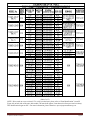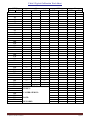
1
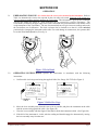
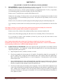
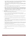
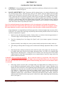
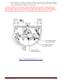
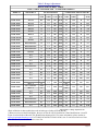
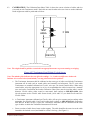
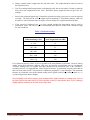
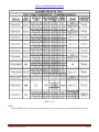
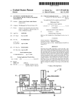
OPERATION & SERVICE MANUAL FOR CABLE TENSIOMETER T5 SOP-TN-001 Rev. # 17 T5 Operation and Service Manual SERIES TABLE OF CONTENTS SECTION I ........................................................................................................................................................................................................ 2 INTRODUCTION AND WARRANTY ................................................................................................................................... 2 1-1 INTRODUCTION ........................................................................................................................................................ 2 1-2 WARRANTY- .............................................................................................................................................................. 2 SECTION II....................................................................................................................................................................................................... 2 GENERAL DESCRIPTION ..................................................................................................................................................... 2 2-1. DESCRIPTION- ........................................................................................................................................................... 2 2-2. PERFORMANCE ......................................................................................................................................................... 2 DETAILED DESCRIPTION .................................................................................................................................................... 3 2-3. SECTORS AND RISERS- ........................................................................................................................................... 3 2-4. TRIGGER-.................................................................................................................................................................... 3 2-5. MAINSPRING- ............................................................................................................................................................ 3 2-6. MOVEMENT AND LINKAGE-.................................................................................................................................. 3 2-7. BRAKE- ....................................................................................................................................................................... 3 2-8. NON-OPERATING PARTS- ....................................................................................................................................... 3 Figure 1-Detailed Description ............................................................................................................................................ 4 SECTION III ..................................................................................................................................................................................................... 4 OPERATION ............................................................................................................................................................................ 5 3-1. PREPARATION FOR USE- ........................................................................................................................................ 5 Figure 2-Wrist Band ........................................................................................................................................................... 5 3-2. OPERATING INSTRUCTIONS-................................................................................................................................. 5 Figure 3-Cable Size Gage ................................................................................................................................................... 5 Figure 4-Method of Operation........................................................................................................................................... 6 SECTION IV ..................................................................................................................................................................................................... 7 SERVICE INSPECTION, MAINTENANCE, AND LUBRICATION..................................................................................... 7 4-1. SERVICE TOOLS REQUIRED- ................................................................................................................................. 7 Figure 5-Pointer Remover Handjack (P/N: T5-AT-1) ..................................................................................................... 7 4-2. SERVICE INSPECTION- ............................................................................................................................................ 7 Figure 6-Lubrication .......................................................................................................................................................... 7 4-3. MAINTENANCE-........................................................................................................................................................ 8 4-4. LUBRICATION- .......................................................................................................................................................... 8 SERVICE TROUBLES AND REMEDIES .............................................................................................................................. 8 Refer to Table 1 for troubleshooting information. ..................................................................................................................... 8 Table 1-Troubleshooting Chart ......................................................................................................................................... 8 SECTION V ...................................................................................................................................................................................................... 9 DISASSEMBLY, INSPECTION, REPAIR AND REASSEMBLY ......................................................................................... 9 5-1. DISASSEMBLY- ......................................................................................................................................................... 9 5-2. INSPECTIONS AND REPAIR- ................................................................................................................................... 9 5-3. REASSEMBLY- ........................................................................................................................................................ 10 SECTION VI ................................................................................................................................................................................................... 11 CALIBRATION TEST PROCEDURES ................................................................................................................................. 11 6-1. GENERAL- ................................................................................................................................................................ 11 6-2. RANGE ADJUSTMENT- .......................................................................................................................................... 11 Figure 7-Adjustment High and Low Screw .................................................................................................................... 12 Table 2- Range Adjustment ............................................................................................................................................. 13 6-3. CALIBRATION- ........................................................................................................................................................ 14 Figure 8-T5 Tensiometer Dead Weight, Typical Set-up ................................................................................................ 14 Table 3-Calibration Range............................................................................................................................................... 15 Table 4-Calibration Data Table....................................................................................................................................... 16 Table 5-Typical Calibration Work Sheet ....................................................................................................................... 19 SECTION VII .................................................................................................................................................................................................. 20 ILLUSTRATED PARTS BREAKDOWN .............................................................................................................................. 20 7-1. GENERAL- ................................................................................................................................................................ 20 7-2. USABLE ON CODE- ................................................................................................................................................. 20 7-3. PART NUMBERING SYSTEM- ............................................................................................................................... 20 Table 6-STD Cable Size to British (CWT) Cable Size Equivalent ............................................................................... 20 Figure 9-T5 Tensiometer Parts Breakdown ................................................................................................................... 21 Table 7-Parts List ............................................................................................................................................................. 22 SOP-TN-001 Rev. 17 T5 Operation and Service Manual Page 1 SECTION I INTRODUCTION AND WARRANTY 1-1 INTRODUCTION- This manual contains descriptive data and instructions for Operating, Maintenance, Overhaul, Repair and Testing of Pacific-Scientific® Cable Tensiometer. It covers all standard models in the T5-2000, T5-8000 series. The T5-3000, T5-4000, and the T5-5000 models are obsolete for future procurement. However, other than the scissors grip, spare parts are available and repair and recalibration can be accomplished. If replacement of a T5-3000 series model is required, order the applicable configuration T5-2000 or T5-8000 series with the same dash numbers as the old configuration. The T55003-106-00 and T5-4008-106-00 are inactive and if a replacement is required, order a T5-8003-106-00 and T5-8008-106-00 respectively. 1-2 WARRANTY- All T5 series Cable Tensiometers have a warranty to the original customer for a period of (1) one year on new units and (6) six months for repaired units from the invoice date. This warranty is to ensure the cable Tensiometer is free of defects in materials and workmanship under correct and normal use. The warranty can be void if the unit has been tampered, alteration, dropped or damaged by an accident. An incorrect operation or handling that may cause an ‘overload action’ and consequently can make the unit to be “out of calibration”, not necessary will be repaired under warranty. Refer to section III for complete operating instructions. The T5 series cable Tensiometer is considered to be “Out of Calibration” when the average readings are more than (+/-) 2 readings points compared to charted readings on the supplied and unique calibration card. Refer to Section 3-2 for operating procedures and to sections 6-3 for calibration and test procedures. Due principally to the uneven surface of the stranded cables, slight variations in readings may occur on the same cable at the same tension. If closest possible accuracy is desired take three or five reading at slightly different locations on the cable and average them. All returns must have a Return Material Authorization (RMA) number. In order to obtain a RMA, please contact our Quality Department via email, [email protected], or via fax: (787) 889-2805. SECTION II 4" 1" 12 101.6mm 38.1mm GENERAL DESCRIPTION 2-1. DESCRIPTION- The series T5 aircraft Tensiometer is a small compact unit designed for determining the tension on aircraft cables. Its use permits the rigging and maintenance of cable loads at the tension specified. 4" 1" 42 T5 CABLE TENSIOMETER 101.6mm PACIFIC SCIENTIFIC COMPANY LUQUILLO, PUERTO RICO 114.3mm The mechanism is contained in aluminum die cast case finished In Black Powder coating. The internal mechanism is metal with the exception of the clear dial glass. MADE IN U.S.A. The Type 5 Tensiometer is built for rugged to long life, continuous service, but is nevertheless a precision instrument and should be treated as such. When not in use, it should be kept in the carrying case provided. With proper care and by following closely the instructions provided, it will give long and satisfactory service. 4" 4" 1" 12 101.6mm 38.1mm T5 CABLE TENSIOMETER 101.6mm PACIFIC SCIENTIFIC COMPANY LUQUILLO, PUERTO RICO The T5-2000 series has a weight .77lb. / .35kg, shipping weight has 2.3lbs. /1.0 kg. The T5-8000 series has a weight 1lb. / .45kg, shipping weight has 2.5lbs. / 1.1 kg. 2-2. 7" MADE IN U.S.A. 177.8mm PERFORMANCE-The Tensiometer shall be capable of operating in the temperature range of -65°F (-53°C) to 160°F (71°C). SOP-TN-001 Rev. 17 T5 Operation and Service Manual Page 2 DETAILED DESCRIPTION 2-3. SECTORS AND RISERS- The offset in the cable is affected by passing it between two hardened pivoting steel sectors (42 and 43) and a retractable hardened steel riser (51) located midway between the sectors. The riser rests on the mainspring leaf assembly and is held in position by riser clip assembly (17). The pivoting sectors function as rollers of large diameters to span the depressions between the cable and pivot slightly caused by offsetting of the cable. The pivots are held in their outward position by sector springs (44) set in recesses in the case (49), causing the sectors to bear against sector pivot pins (41) which are a press fit into case (49). (See Figure 1) 2-4. TRIGGER- In order to pass a tight cable between the two sectors (42 and 43) and over the riser (51), the riser is retracted by lowering one end of which is attached to the main spring pivot pin (46). The free end of the mainspring leaf assembly rests on two trigger rollers (31), which are attached to lever trigger assembly (34 See Figure 9) of the trigger assembly (30 thru 34). The lever assembly or trigger lever project from the side of the instrument case. Opening the lever assembly or trigger lever lowers one end of the mainspring leaf assembly (16, See Figure 1) and the riser (51). Closing the lever assembly or trigger lever raises the mainspring leaf assembly along with the riser, and therefore lever raises the mainspring leaf assembly along with the riser, and therefore creates the offset in the cable. An angled flat trigger spring (29) is provided to give an over center snap action to the lever assembly or trigger lever. The drawing of the T52000 Series Tensiometer on the title page shows the standard lever assembly used only on this series. The T5-8000 series utilizing a mitten grip is also depicted on the title page. 2-5. MAINSPRING- The reaction of the cable offset bows the mainspring leaf assembly (16). An arm riveted to the fixed end of the main spring leaf assembly becomes tangent to the bowed mainspring leaf assembly, producing a substantial movement to the opposite free end of the mainspring leaf assembly. 2-6. MOVEMENT AND LINKAGE- The movement referred to in the preceding paragraph is transmitted by the linkage rod (15) and sleeve assembly (11) to the movement assembly (28). The linkage rod and sleeve assembly move as a unit, except when the pointer (5) is locked in position. The movement assembly is a self-contained brass unit comprised of a toothed segment meshing with a pinion gear on the pointed arbor. The outer end of the segment meshing with a pinion gear on the pointed arbor. The outer end of the segment consists of a slotted arm, to which the linkage rod (15) is attached. The purpose of the slot is to provide a means of adjusting the range of the Tensiometer. A hairspring is provided in the movement to eliminate backlash in the gears and to return the pointer to zero. An adjustable segment stop-screw (7) is provided to limit the travel of the segment, thus providing a more positive zero adjustment. 2-7. BRAKE- The brake lever rod (24) serves to lock the Tensiometer pointer in the event that dial (6) cannot be seen when taking a reading. The lock consists of two flat bronze springs (20 and 21). The longer brake spring (20) is set to normally bear against the segment of the movement, to hold it by friction when the brake lever is in the locked position. The shorter brake plunger spring (21) is to provide a snap action to the brake lever rod. Rotating the brake lever rod (24) lifts the two springs by means of brake plunger (22), which normally rides on a recessed flat in the brake lever rod. 2-8. NON-OPERATING PARTS- The foregoing covers the operating parts of the Tensiometer. The remaining parts are the case (49) on which all the operating parts and the dial (6) are mounted, and the cover (2) into which the glass (3) and bezel (4) are fitted. SOP-TN-001 Rev. 17 T5 Operation and Service Manual Page 3 24 A 51 28 25 C 41 43 16 19 46 17 15 42 31 30 32 33 45 29 18 19 C B D B 25 23 D 10 20 34 22 49 2 6 5 12 11 1 35 50 3 47 7 4 HIGH RANGE SPREAD ADJUSTING SCREW HIGH RANGE POSITION ADJUSTING SCREW ZERO ADJUSTING SCREW LOW RANGE A SECTION A-A 44 24 8 14 21 9 13 SECTION B-B SECTION C-C SECTION D-D Figure 1-Detailed Description KEY TO FIGURE 1 1. Case Screw 16.Mainspring Leaf Assembly 33. Trigger Spring Pin 2. Cover 17.Riser Clip Assembly 34. Lever Trigger 3. Glass 18. Screw 35. Nameplate 4. Bezel 19. Washer 41. Sector Pivot Pin 5. Pointer Assembly 20. Brake Spring 42. Left Hand Sector Assembly 6. Dial 21. Brake Plunger Spring 43. Right Hand Sector Assembly 7. Stop-Screw 22. Brake Plunger 44. Sector Spring 8. Spacer Washer 23. Grove Pin 45. Trigger Pivot Pin 9. Channel Nut 24. Brake Lever Rod 46. Main Spring Pivot Pin 10. Screw 25. Screw 47. Dial Mounting Pin 11. Sleeve Assembly 12. Riser Clip Spring 28. Movement Assembly 29. Trigger Spring 49. Case 50. Drive Screw 13. Spring 14. Washer 30. Ring Lock 31. Trigger Roller 51. Riser 15. Rod Linkage 32. Roller Pin SOP-TN-001 Rev. 17 T5 Operation and Service Manual Page 4 SECTION III OPERATION 3-1. PREPARATION FOR USE- It is vital to have the correct riser mounted on the instrument. Refer to Table 4 to determine the correct riser required for the size cable to be tested. Selection of the wrong riser will give incorrect readings and may damage the Tensiometer. This information is given on the calibration card for each model (See Figure 4). Each calibration card is prepared for a specific Tensiometer. The serial number, noted near the upper right corner of the calibration card, must match the serial number noted on the nameplate of the Tensiometer. The use of non-matched sets will give incorrect readings and render the Tensiometer out of calibration. The brake rod must also be checked to see that it is in the unlocked position before clamping the instrument on the cable. For avoid damage on common use, the operator shall be use the Wrist Band adjustable (54 on fig. 9). T5 CABLE TENSIOMETER T5 CABLE TENSIOMETER PACIFIC SCIENTIFIC COMPANY LUQUILLO, PUERTO RICO PACIFIC SCIENTIFIC COMPANY LUQUILLO, PUERTO RICO MADE IN U.S.A. MADE IN U.S.A. Figure 2-Wrist Band 3-2. OPERATING INSTRUCTIONS- Operate the Tensiometer in accordance with the following instructions: a. Confirm cable size being tested using the supplied Cable Size, Gauge, P/N T523.(See Figure 3) 1Ø 4 3 5 7 9 5 32 1 32 3 32 1 32 1 16 8 16 16 4 CABLE DIA. 3 8 3 5 7 9 5 32 1 32 3 32 1 32 1 16 8 16 16 4 1Ø 4 Ø GAUGE RD. 992 KM. 0.3 INDUSTRIAL PARK. LUQUILLO, P.R. 00773 (U.S.A.) EXAMPLE CABLE optimanufacturing INCH FRACTION 3 8 INCH FRACTION optimanufacturing CABLE DIA. PHONE (787)889-2285 www.aircrafttensiometer.com Ø GAUGE RD. 992 KM. 0.3 INDUSTRIAL PARK. LUQUILLO, P.R. 00773 (U.S.A.) PHONE (787)889-2285 www.aircrafttensiometer.com T523 Figure 3-Cable Size Gage b. Move the lever assembly away from the case as far as possible, and place the instrument on the cable with the sectors resting against the cable. (See Figure 4a.) c. Close the lever assembly with the fingers of the hand in which the instrument is held. (See Figure 4b.) d. If the dial of the instrument is visible, take the reading and then disengage the instrument by moving the lever assembly away from the case. SOP-TN-001 Rev. 17 T5 Operation and Service Manual Page 5 Due principally to the uneven surface of the stranded cables, slight variations in readings may occur on the same cable at the same tension. If closest possible accuracy is desired take three or five reading at slightly different locations on the cable and average them. e. If it is necessary to take a reading when the dial cannot be seen, the pointer assembly may be locked in position by pushing forward the brake lever rod at the top left of the case. The pointer assembly is unlocked by returning the brake lever rod to its original position. Never lock the brake lever rod until the instrument is clamped on the cable where the load is to be measured, or a false reading will result. f. Convert the dial reading to tension in pounds by referring to the calibration chart. A typical conversion is shown in Figure 4, where a dial reading of 55 points with the instrument testing a 1/16 inch cable and Riser #1 is converted to 160 pounds tension by referring to the calibration chart. (See Figure 4). WARNING. Do not overload the instrument – that is, permit the Pointer to go beyond the “100” mark on the dial. When first applying to a tight cable, close the Trigger slowly and watch the Pointer to be sure it will not go above the “100” mark when the load is fully applied. Permanent damage may be done to the instrument when it is overloaded. 1/16 Ø EXAMPLE CABLE SIZE 4a T5 CABLE TENSIOMETER PACIFIC SCIENTIFIC COMPANY LUQUILLO, PUERTO RICO MADE IN U.S.A. RISER # 1 EXAMPLE 1/16 Ø EXAMPLE CABLE DIAMETER 4b T5 CABLE TENSIOMETER PACIFIC SCIENTIFIC COMPANY LUQUILLO, PUERTO RICO MADE IN U.S.A. DE IN U.S.A. Figure 4-Method of Operation It should be remembered that the tension on the control cables of an aircraft (unless the aircraft is equipped with automatic cable tension regulators) varies with temperature. For instance, cables may be rigged at 50-pounds tension when the temperature is 24 degrees C (75 degrees F). Later the cables may be checked when the aircraft has been standing in the direct sunlight at a temperature of 38 degrees C (100 degrees F) and found to have a tension of 100 pounds or more. Under these conditions, reports are sometimes received that the Tensiometer is inaccurate because the cables were known to have been originally rigged at 50-pounds. A comparatively small change in temperature will make an appreciable difference in the tension of the cables. Under these conditions, therefore, it should be assumed the instrument is accurate and the cables are under higher or lower tension, as the case may be. SOP-TN-001 Rev. 17 T5 Operation and Service Manual Page 6 Cable Tensiometer should not be used for adjusting the rig load in a cable system where an automatic cable tension regulator is installed. In all cases, such cable systems should be rigged by adjusting them so that the pointer on the cable tension regulator scale indicates the correct number based on the surrounding temperature, as indicated on the chart provided in the Airplane Service manual. The Tensiometer may be used to check the tension obtained, but it must be remembered that the actual cable tension will vary from the nominal, depending upon the errors in the instrument itself, manufacturing tolerance of springs in the regulators, rate of the regulator spring, and condition of the control cable. Cable tension readings taken on regulated control systems by means of a Tensiometer could, therefore, be misleading. Note: The attitude of the indicator does not affect the readings – i.e., it makes no difference whether the Indicator is in vertical or horizontal attitude, or at any point between these positions. SECTION IV SERVICE INSPECTION, MAINTENANCE, AND LUBRICATION 4-1. SERVICE TOOLS REQUIRED- A suitable Pointer Remover, Handjack is necessary as well as the regular instrument repair shop tools. Since it is necessary to press the pointed assembly onto the spindle tightly to prevent slippage when the pointer assembly snaps back accidentally, some types of pointed assembly removers are not satisfactory. A suitable Pointer Remover, Handjack for this purpose is illustrated in Figure 5 and may be purchased from OPTI Manufacturing Corp., Part Number T5-AT-1. Figure 5-Pointer Remover Handjack (P/N: T5-AT-1) 4-2. SERVICE INSPECTION- When a Tensiometer is in daily use, the cover, pointer assembly, and dial may be removed every six (6) months and the mechanism cleaned, oiled, and carefully inspected for any obvious damage. (See Figure 6) LEGEND High-Grade Hydraulic Oil Dow Corning Grease #33 fluid type or equivalent to NATO type G-395 fluid type per MIL-PRF-81322 Figure 6-Lubrication The recommended recalibration interval is every (12) twelve months. Always check the tensiometer when it accidentally dropped down, and recalibrated if it is necessary. For calibration procedures, refer to Section VI. Note: While the Tensiometer is in warranty, recommended not open the unit or break the seal security, if require repair, please request a RMA number. Refer to section I “Warranty”. SOP-TN-001 Rev. 17 T5 Operation and Service Manual Page 7 4-3. MAINTENANCE- To clean, remove the cover, pointer assembly, and dial. Wash the case and internal mechanism with cleaning solvent. Low air pressure may be used to dry the internal mechanism. CAUTION: UNDER NO CIRCUMSTANCES SHALL HIGH PRESSURE AIR BE USED, AS THIS WILL DAMAGE THE HAIRSPRING OF THE INTERNAL MECHANISM. If the internal mechanism is extremely dirty it should be cleaned thoroughly by disassembling, as outlined in Section V, each part washed individually in cleaning solvent, dried, and lubricated. 4-4. LUBRICATION- After making certain the internal mechanism is clean and dry, lubricate in accordance with the lubrication chart (See Figure 6). Apply oil and grease with the end of a jeweler’s screwdriver or flattened wire. Avoid excessive use of oil or grease, as this only serves to collect dirt. SERVICE TROUBLES AND REMEDIES Refer to Table 1 for troubleshooting information. Table 1-Troubleshooting Chart TROUBLE Bent pointer assembly (5) Pointer assembly (5) not returning to zero. Sectors (42 or 43) not returning to normal position. Brake lever rod (24) failing to lock or release CAUSE REFER TO FIGURE 9 Overloading caused by clamping Tensiometer on a cable loaded in excess of Tensiometer calibrated range, or using wrong riser Binding in sleeve assembly (11) due to misalignment of Linkage rod (15) in sleeve assembly or excessive dirt Sector springs (44) bent out of contact with sector pivot pin (41) Straighten pointed assembly and adjust it to zero in case minor overload. If mainspring leaf assembly is bent, refer to Section V for repair Clean sleeve assembly and realign linkage rod if necessary Screw (18) loose or brake spring (20) out of alignment Tighten screw and, if necessary, bend spring so that it clears segment about 1/64 inch when in the unlocked position If necessary, remove trigger spring pin, polish contact surface. Replace and lubricate spring pin and trigger rollers (31) as instructed in lubrication chart (See Figure 6) Press pointer assembly tightly on spindle of movement assembly. If hole in pointer assembly is enlarged, squeeze pointer assembly bushing together slightly to ensure a press fit Trigger assembly (30-34) binding Lack of lubrication on roller pin (32) or trigger spring pin (33) Loose pointer assembly Pointer assembly (5) not pressed on to spindle of movement assembly (28) far enough, or hole in pointer assembly is enlarged SOP-TN-001 Rev. 17 T5 Operation and Service Manual REMEDY Straighten or replace sector springs Page 8 SECTION V DISASSEMBLY, INSPECTION, REPAIR AND REASSEMBLY 5-1. DISASSEMBLY- Although full disassembly procedures are provided, disassemble Tensiometer only to the extent required to replace or repair the defective part. (See Figure 9) Remove two case screws (1). Remove pointer assembly (5), using handjack (P/N: T5-AT-1), or equivalent, to avoid bending spindle of movement assembly (28), then lift off dial (6). Remove screw (7) and slide sleeve assembly from linkage rod (15). Unhook riser clip spring (12) from pin drive screw (48) and remove mainspring leaf assembly (16) and riser clip assembly (17) from mainspring pivot pin (46). Note position of clip assembly to serve as an aid during reassembly. Remove screw (18), washer (19a), brake spring (20), brake plunger spring (21) and brake plunger (22). If it is necessary to remove brake lever rod (24), first remove groove pin (23) then brake lever rod will slide out. Note: Before removing screws (25a), mark their position on the movement assembly (28) so that when reassembled, movement assembly will be located in its original position. Remove screws (25a), washers (19b), and then carefully remove movement assembly (28). Remove screw (25b) and trigger spring (29), then remove lever assembly (T509 or T5142) from case. If it is necessary to remove sector assemblies (42 and 43), press out pins (41) then removes sector assemblies and sector springs (44). Note: Complete disassembly and overhaul of the Tensiometer should not be necessary, except where Tensiometer has been used over a long period of time without routine maintenance, or where accidents and/or service operating conditions have resulted in major damage to the unit. 5-2. INSPECTIONS AND REPAIR- Perform the inspection and repair procedures in accordance with the following instructions. It is suggested a strong light and magnification be used when performing the inspection procedures.(See Figure 9) a. Inspect all parts for nicks, scratches, corrosion, or cracks. b. Check case assembly (49) for loose pins (41, 45, and 46). Pin should be a tight fit in case assembly. If pins are slightly loose, swaging the metal around the hole with a hollow punch may tighten them. Make certain when swaging that pins are in vertical alignment. If bearing surface of pin are badly marred, replace pins. c. Inspect all threaded parts for worn or damaged threads, especially in cover (2) and case (49). Chase or tap any minor imperfections of threads, providing function and fit of threads are in no way impaired. If threads are stripped or badly damaged, replace the applicable part. d. Check arm of main spring leaf assembly (16) for alignment. The free end should be slightly above the center of the main spring leaf assembly bearing and should clear the bearing by approximately 0.010 inch. Linkage rod (15) should fit freely into arm with sufficient side play to permit easy alignment with sleeve assembly (11) when parts are assembled. If rivets in end of main spring leaf assembly are loose, tighten or replace. SOP-TN-001 Rev. 17 T5 Operation and Service Manual Page 9 e. Check fit of fingers of riser clip assembly (17) on lug of main spring leaf assembly. There shall be no binding. If there is any binding, fingers of riser clip assembly may be bent slightly to eliminate the binding. This condition is also applicable when parts are assembled in case (49). f. Inspect trigger rollers (31) for freedom of rotation on roller pin (32). If any binding is evidenced, remove roller rings (30), then remove trigger rollers (31). Clean and polish roller pin (32) and holes in trigger rollers (31). g. Check roller pin (32) and trigger spring pin (33) for a tight secure fit in lever assembly (T509 or T5142). Swage areas around pins if necessary to produce a tight secure fit. h. Inspect action of segment and pinion of movement assembly (28). Action should be smooth with no binding. Check all screws in the movement assembly for tightness. If zero adjustment screw in segment stop of movement is loose, removing the screw, bending the segment stop ears closer together and replacing screw may tighten it. If any further or obvious damage of the movement assembly is evidenced it should be returned to the manufacturer for repair or replacement. 5-3. REASSEMBLY- Reassemble the Tensiometer in the same order as the key index number assigned to the exploded view illustration, noting the following:(See Figure 9) a. Attach sectors (42 and 43), making certain that stop pins properly engage sector springs (44). b. Install lever assembly (T509 or T5142) and trigger spring (29). Secure trigger spring (29). Secure trigger spring in position with screw (25b). c. Install movement assembly (28) in case (49) and retain in position with screw (25a) and washer (19b). d. Insert brake rod lever (24) through hole in case (49), then install groove pin (23) in brake rod lever. e. Assemble brake plunger spring (21) and brake spring (20) into case, and secure in position with screw (18) and washer (19a). f. Place riser assembly clip (17) and main spring leaf assembly (16) on main spring pivot pin (46). Attach one end of riser clip spring (12) to riser clip assembly, and secure the other end of riser clip spring to case with drive screw (48). g. Locate linkage rod (15) in hole provided in main spring leaf assembly (16), followed by spring (13) and washer (14). Slide sleeve assembly (11) on to linkage rod (15) and secure to movement assembly (28) with channel nut (9), washer (8), and screw (7). h. Position dial (6) in place, then install pointer assembly (5) on spindle of movement assembly (28). i. Before completion of assembly, adjust range and, if necessary, make adjustments. Refer to Section VI. j. Place glass (3) followed by bezel (4) in cover (2). Place cover on case (49) and secure in place with screws (1). k. Recalibrate as necessary. Refer to Section VI. SOP-TN-001 Rev. 17 T5 Operation and Service Manual Page 10 SECTION VI CALIBRATION TEST PROCEDURES 6-1. GENERAL- Testing and adjustment procedures require that a satisfactory calibration device be available. One such device is shown in Figure 8. 6-2. RANGE ADJUSTMENT- Each Tensiometer shall be adjusted prior to its original calibration to give the maximum range setting. Maximum range setting in this instance means the highest and lowest dial reading on the Tensiometer to utilize the full dial scale range of 0 to 100. The Range Adjustment Table, Table 2, shows the cable size and load in pounds, which will give the high and low readings. For example, on Model T5-2002-104, set the high readings between 93 and 96 (typically) on the dial of the Tensiometer, utilizing a 1/4-inch diameter cable with a tension load of 300 pounds. If the Tensiometer range is adjusted correctly, then the low reading value on the dial should be between 9 and 12, utilizing a 1/16-inch diameter cable with a tension load of 30 pounds.(See Table 2) Note: If a considerable amount of range adjustment work is to be performed, it will expedite the operation to obtain an extra dial, Part Number T559, and cut away the center of the dial so that just the scale figures remain. The range adjustment can then be made without having to remove the pointer assembly and the dial each time. Range adjustment is accomplished by the following procedure, with the assumption that a cut-away dial is being used. If a cut-away dial is not being used, then the pointer assembly and dial will have to be removed each time an adjustment is required. a. Install cut-away dial and pointer assembly. Rotate pointer in a clockwise direction approximately 21/2 turns to apply a load to hairspring in the movement assembly. b. Turn Zero Adjusting Screw Low Range (See Figure7) until it just contacts segment of movement assembly. c. If pointer assembly is not reading zero, remove pointer assembly and reposition so that it reads zero. d. Take readings at the high and low range points as indicated in the Range Adjustment Table.(see Table 2) e. If the high and low readings are both two to three divisions of the scales, high or low, the range may be brought within limits specified in the Range Adjustment Table, (see Table 2) by adjusting High Range Position Adjusting Screw. Turning the screw clockwise raises the range (moves the pointer counterclockwise on the dial), and turning the screw counterclockwise lowers the range (moves the pointer clockwise on the dial). WARNING: Do not overload the instrument – that is, permit the Pointer to go beyond the “100” mark on the dial. When first applying to a tight cable, close the Trigger slowly and watch the Pointer to be sure it will not go above the “100” mark when the load is fully applied. Permanent damage may be done to the instrument when it is overloaded. f. If the range spread is incorrect, that is, the high reading is too high and the low reading is too low, it may be adjusted by adjusting the position of sleeve assembly (See Figure 7) where it attaches to the slotted arm of the movement. Loosen High Range Spread Adjusting Screw. With High Range Spread Adjusting Screw loose the sleeve assembly can be moved in toward the movement if the range spread is too small (i.e., if high reading is low and low reading is high), or away from the movement if the range spread is too great (i.e., the high is too high and the low reading too low). This is a delicate adjustment requiring only a small amount of movement and should be made carefully. When the adjustment has been made and the range spread is within limits, tighten High Range Spread Adjusting Screw. (See Figure 7) SOP-TN-001 Rev. 17 T5 Operation and Service Manual Page 11 g. When adjustment is complete, reset pointer assembly if necessary, to zero with the zero adjusting screw. Remove pointer assembly and cut-away dial. Replace normal dial and pointer assembly, making certain that pointer assembly is on the zero mark. Note: Due principally to the uneven surface of the stranded cables, slight variations in readings may occur on the same cable at the same tension. If closest possible accuracy is desired take three or five reading at slightly different locations on the test area of the cable and average them. It is considered a unit to be ‘out of calibration’ when the average reading is more than (+/-) 2 pts. against the charted readings in the calibration card. HIGH RANGE SPREAD ADJUSTING SCREW HIGH RANGE POSITION ADJUSTING SCREW ZERO ADJUSTING SCREW LOW RANGE Figure 7-Adjustment High and Low Screw SOP-TN-001 Rev. 17 T5 Operation and Service Manual Page 12 Table 2- Range Adjustment RANGE ADJUSTMENT TABLE TYPE 5 CABLE TENSIOMETER – STANDARDS MODELS SET HIGH READING MODEL No. OLD MODEL #: - - RISER USED ON CABLE T5-2001-101-00 401-1J-2 #2C 3/16 150 T5-2001-102-00 401-1A-2 #1 1/8 T5-2001-104-00 401-1C-2 #1 T5-2002-101-00 402-1J-2 T5-2002-103-00 T5-2002-104-00 LOW READING SHOULD THEN BE RISER USED ON CABLE AT LOAD TO READ 82–86 #1 1/16 10 4-7 160 93-96 #1 1/16 30 9-12 1/8 200 93-96 #1 1/16 30 9-12 #3 1/4 150 91-96 #1 1/16 10 5-8 402-1B-2 #3 1/4 250 93-96 #1 1/16 30 9-12 402-1C-2 #3 1/4 300 93-96 #1 1/16 30 9-12 N/A #3 1/4 300 93-96 #1 1/16 30 9-12 T5-2002-105-00 402-1D-2 #3A 1/4 400 93-96 #1 1/16 30 4-7 T5-2002-301-00 Dual Calibration* #3 1/4 150 88-95 #1 1/16 10 5-7 T5-2002-304-00 Dual Calibration* #3 1/4 300 80-85 #1 1/16 30 6-13 T5-2002-401-00 Dual Calibration* #3 70 CWT 150 94-96 #1 5 CWT 10 5-7 T5-2004-113-00 404-1K-2 #1 1/8 100 75-79 #1 1/16 10 5-7 T5-2006-115-00 N/A #1 1/16 60 74-78 #1 1/16 5 7-10 T5-8002-104B-00 N/A #3A 1/4 300 95-99 #1 1/16 10 3-7 T5-8002-105-00 N/A #3A 1/4 400 93-96 #1 1/16 30 4-7 T5-8002-211-00 N/A #2 1/8 350 91-96 #2 1/16 35 6-11 T5-8002-401-00 Dual Calibration* #3 70 CWT 150 94-96 #1 5 CWT 10 5-8 T5-8003-106-00 N/A #2C 1/4 600 94-96 #2C 3/16 40 6-9 T5-8003-107-00 N/A #2C 1/4 800 94-96 #2C 3/16 100 5-8 T5-8003-108-00 N/A #2C 1/4 1000 94-96 #2C 3/16 200 7-10 T5-8003-209-00 N/A #4 3/8 400 91-96 #4 1/4 200 9-12 REV M AND BEFORE 1/4 1300 94-96 250 8-11 1/4 1600 94-96 3/16 300 8-11 5/16 1600 94-96 **#2 #2C **#2 #2C #2C 3/16 REV. N N/A **#2C #3 **#2C #3 #3A 1/4 300 8-11 T5-8005-111-00 N/A #2C 1/4 2000 94-96 #2 3/16 500 9-12 T5-8008-106-00 N/A #3 1/4 600 94-96 #2 1/8 40 4-7 T5-8008-306-00 Dual Calibration* #3 1/4 600 81-86 #2 1/8 40 6-9 T5-8103-406-00 Dual Calibration* #2C 1/4 600 96-99 #2C 3/16 40 6-9 T5-8203-108-00 N/A #3B 3/8 1000 94-98 #3B 3/8 200 45-48 T5-2002-104A-00 T5-8005-109-00 T5-8005-110-00 REV. N REV M AND BEFORE T5-8005-110-00R AT TO LOAD READ FM-TN-078 Rev. E Range Adjustment Table *Dual calibration is those models that read on both type of cables (STD & British). **Risers used on revision M and before, the new revision N will be identified on “Plate Identification“ (item#35 Figure 9) on back side of the unit. This identification begun on 2013. For more information, please contact us: [email protected]. For T5-8002-105-00 and T5-2002-105-00, riser #3 can be used in lieu of riser #3A. For riser #3, use the same limit as riser #3A. SOP-TN-001 Rev. 17 T5 Operation and Service Manual Page 13 6-3. CALIBRATION- The Calibration Data Sheet, Table 4, shows the correct selection of cables and riser sizes used on each Tensiometer model. Particular care must be taken to be sure risers are used as indicated. Dead weight tests could be performed as follows: LUQUILLO, PUERTO RICO PACIFIC SCIENTIFIC COMPANY MADE IN U.S.A. MADE IN U.S.A. LUQUILLO, PUERTO RICO PACIFIC SCIENTIFIC COMPANY 3' MIN T5 CABLE TENSIOMETER TEST AREA T5 CABLE TENSIOMETER 12" 12" WEIGTH Note: The weight should be guided or restrained in an appropriate manner to prevent rotating or swinging. Figure 8-T5 Tensiometer Dead Weight, Typical Set-up Note: The attitude of the indicator does not affect the readings – i.e., it makes no difference whether the Indicator is in vertical or horizontal attitude, or at any point between these positions. a. The Tensiometer instrument shall be calibrated on the same type of cables on which the Tensiometer instrument will be used (such as coated cables used externally on helicopters). The T5 series cable Tensiometers are standard calibrated on Flexible, wire rope, for aircraft control cables. When using coated cables, select the appropriate size of riser to accommodate the cables increased size. Annotate riser used on the Certification label and/or Calibration Chart. Riser must be sized the cable’s outside diameter. Flexible cables, either coated or non-coated, shall conform to MIL-DTL-83420. Most Aircraft systems use the Flexible cable. Some aircraft, (A-10 and F-15), use both Flexible and NonFlexible cables. b. A Tensiometer instrument calibrated on Flexible cable will not give accurate tension readings when measuring Non-Flexible cable. Non-Flexible cables shall conform to MIL-DTL-87161, (Supersedes MIL-W87161 & MIL-W-5693). Again, the Tensiometer instrument shall be calibrated on the same type of cables on which the Tensiometer instrument will be used. c. Fasten a section of cable from a beam or other support. The cable should be the same size as the cable intended to be checked or used, and should be at least 3 feet long. (See Figure 8.) SOP-TN-001 Rev. 17 T5 Operation and Service Manual Page 14 d. Hang a certainly known weight to the free end of the cable. The weight should be at the low limit of the required test area. e. Take five readings at different positions on the hanging cable, but no closer than 12 inches to either the fixed end or the weighted end of the cable. Record the known weight and the average of the five readings. f. Increase the weight and repeat step d. Repeat this procedure as often as necessary to cover the required test range. The result will be a list of weights and corresponding T5 Tensiometer readings, which can be used as a valid calibration chart. See Figure 4 for an example of a completed calibration chart. g. If the successive weights of step e are close enough, straight-line interpolation may be used for intermediate values. The Table 3 gives recommended check intervals related to the calibration range for most conditions. Table 3-Calibration Range Calibration Range (Lbs) Check Weight Intervals (LBS) 0 – 100 10 100 – 200 25 200 – 400 50 400 – 1000 100 1000 – Up 200 For in-plant test purposes, cables as close as possible to the main diameter are desirable. However, during vendor testing and calibration, different cable runs and possible pre-stretching may be encountered. Therefore, readings may vary slightly from those indicated on the calibration card. If this variation is considered critical, it is suggested that “Dead Weight Calibration” be performed, using the same cable as that to be used in the aircraft. This procedure is outlined in paragraph 6-3, steps b through f. The maximum tolerance or permissible error for the charted reading values against actual average readings values is (+/-) 2 points using accurate known weights. Due principally to the uneven surface of the stranded cables, slight variations in readings may occur on the same cable at the same tension. If closest possible accuracy is desired take three or five reading at slightly different locations on the cable and average them. SOP-TN-001 Rev. 17 T5 Operation and Service Manual Page 15 Table 4-Calibration Data Table (Sheet 1 of 3) NOTE: *For T5-2002-105-00, riser #3 can be used in lieu of riser #3A. For riser #3, use the same limit as riser #3A. SOP-TN-001 Rev. 17 T5 Operation and Service Manual Page 16 (Sheet 2 of 3) NOTE: *For T5-8002-105-00, riser #3 can be used in lieu of riser #3A. For riser #3, use the same limit as riser #3A. SOP-TN-001 Rev. 17 T5 Operation and Service Manual Page 17 (Sheet 3 of 3) NOTE: *Riser used on a new revision N. To verify revision letter, please refer to “Plate Identification” (item#35 Figure #9) on back side of the unit. After model # N letter shall appear, if not then unit is from previous revision(s). This identification begun on 2013. For more information, please contact us: [email protected] SOP-TN-001 Rev. 17 T5 Operation and Service Manual Page 18 Table 5-Typical Calibration Work Sheet RISER LOAD CABLE 10 lbs-tension 15 20 25 30 35 40 45 50 60 70 80 90 100 110 120 130 140 150 160 170 180 190 200 210 220 230 240 250 260 270 280 290 300 320 340 350 360 370 380 390 400 1/16 #1 3/32 ----------------------------------------INSTRUMENT NO. MODEL: #2C 1/8 5/32 #3 3/16 7/32 1/4 --------------------- CALIBRATED BY: DATE: REMARKS: SOP-TN-001 Rev. 17 T5 Operation and Service Manual Page 19 SECTION VII ILLUSTRATED PARTS BREAKDOWN 7-1. GENERAL- This Illustrated Parts Breakdown lists and describes the parts for Cable Tensiometer, Pacific Type T5, manufactured by OPTI Manufacturing Corp., Luquillo, Puerto Rico 00773. (Manufactured in the past by Pacific Scientific, Kin-Tech Division.) 7-2. a. Index numbers on the exploded view are numerically arranged in the Figure and Index No. Column of the parts list. b. The Part Number Column contains part numbers only. These part numbers are used exclusively to identify parts. c. The Description Column contains the complete description of each part, with dimensions if necessary, to identify the part. d. The quantities listed for component parts in the Units per Assy. column of the Illustrated Parts Breakdown are the total quantities used at the location indicated. Quantities listed for component parts, indented under the subassemblies, are the quantities used per subassembly; therefore, the quantities specified are not necessarily the total used per equipment. USABLE ON CODE- Coding is used only where more than one equipment is listed in the same parts list. An example of the letter symbols used is at the heading of each parts list. Part variations are indicated by a letter symbol in the Usable on Code column. Blank spaces are the Usable on Code column indicate the part is used in all equipment covered by the Illustrated Parts Breakdown. 7-3. PART NUMBERING SYSTEM- For convenient reference, the 28 assemblies are covered in two series, T5-2000 and T5-8000. The first numeral after the first dash in the part number determines the series to which that assembly belongs. For example, T5-2002-101-00 belongs to the T5-2000 series. The significance of the series numbers is that all assemblies in each series are made up of the same parts. The only difference between assemblies within a series is in the range and calibration, details of which are explained in Table 4. Table 6-STD Cable Size to British (CWT) Cable Size Equivalent 1/16" 3/32" 1/8" 5/32" 3/16" 7/32" 1/4" 9/32" 5/16" SOP-TN-001 Rev. 17 T5 Operation and Service Manual 3 5 10 15 25 35 45 70 80 Page 20 Figure 9-T5 Tensiometer Parts Breakdown SOP-TN-001 Rev. 17 T5 Operation and Service Manual Page 21 Table 7-Parts List FIG. & INDEX NO. 9 1 2 3 4 5 6 7 8 9 10 11 12 13 14 15 PART NO. T5-2001-101-00 T5-2001-102-00 T5-2001-104-00 T5-2002-101-00 T5-2002-103-00 T5-2002-104-00 T5-2002-104A-00 T5-2002-105-00 T5-2002-301-00 T5-2002-304-00 T5-2002-401-00 T5-2004-113-00 T5-2006-115-00 T5-8002-104B T5-8002-105-00 T5-8002-211-00 T5-8002-401-00 T5-8003-106-00 T5-8003-107-00 T5-8003-108-00 T5-8003-209-00 T5-8005-109-00 T5-8005-110-00 T5-8005-111-00 T5-8008-106-00 T5-8008-306-00 T5-8103-406-00 T5-8203-108-00 COML # 0901100-06 T569 T561 T563 T562 T559 T545 T546 T547 COML # MS35265-4 T536 T535 T5156 T533 T526 T525 T524 SOP-TN-001 Rev. 17 T5 Operation and Service Manual DESCRIPTION CABLE TENSIOMETER CABLE TENSIOMETER CABLE TENSIOMETER CABLE TENSIOMETER CABLE TENSIOMETER CABLE TENSIOMETER CABLE TENSIOMETER CABLE TENSIOMETER CABLE TENSIOMETER CABLE TENSIOMETER CABLE TENSIOMETER CABLE TENSIOMETER CABLE TENSIOMETER CABLE TENSIOMETER CABLE TENSIOMETER CABLE TENSIOMETER CABLE TENSIOMETER CABLE TENSIOMETER CABLE TENSIOMETER CABLE TENSIOMETER CABLE TENSIOMETER CABLE TENSIOMETER CABLE TENSIOMETER CABLE TENSIOMETER CABLE TENSIOMETER CABLE TENSIOMETER CABLE TENSIOMETER CABLE TENSIOMETER . SCREW, PHILLIPS FLAT HEAD # 4-40 x 1-1/8” LONG . COVER . GLASS . BEZEL . POINTER ASSEMBLY . DIAL . SCREW . SPACER WASHER . CHANNEL NUT . SCREW, FILLISTER HEAD, # 2-56 x5/16” LONG . SLEEVE ASSEMBLY . . SLEEVE . . PLATE . RISER CLIP SPRING . . SPRING . . WASHER . . ROD LINKAGE UNITS PER ASSY USABLE ON CODE REF REF REF REF REF REF REF REF REF REF REF REF REF REF REF REF REF REF REF REF REF REF REF REF REF REF REF REF 2 1 1 1 1 1 1 1 1 1 1 1 1 1 1 1 1 A A A A A A A A A A A A A B B B B C C C C C C C B B C D ALL ALL ALL ALL ALL ALL ALL ALL ALL ALL ALL ALL ALL ALL ALL ALL ALL Page 22 FIG. & INDEX NO. 9 16 17 18 19 20 21 22 23 24 25 26 27 28 29 30 31 PART NO. T520 T522 T525 T526 T527 T530 T525 T526 T5152 T5146 T525 T526 T614-1 T613-1 T525 T526 T574 T572 T574-1 T572-1 T573 T575 T575-1 T576 COML # MS35265-14 AN960-4 T551 T554 T553 COML # 0913200-01 T531 COML # 0901100-04 T5138-80 T5138-20 0922100.88 0922100.89 T5184-04 T5184-02 T5185-51 T5185-52 WI-CU-001 T571/T571-1 T552 T507 T518 T506 T517 SOP-TN-001 Rev. 17 T5 Operation and Service Manual DESCRIPTION . .MAIN SPRING ASSEMBLY . . LEAF ASSEMBLY . . WASHER . . SPRING . .MAIN SPRING ASSEMBLY . . LEAF ASSEMBLY . . WASHER . . SPRING . .MAIN SPRING ASSEMBLY . . LEAF ASSEMBLY . . WASHER . . SPRING . .MAIN SPRING ASSEMBLY . . LEAF ASSEMBLY . . WASHER . . SPRING . CLIP RISER ASSEMBLY . .CLIP . CLIP RISER ASSEMBLY . .CLIP . .PIN . CLIP RISER ASSEMBLY . CLIP RISER ASSEMBLY . .PIN . SCREW, FILLISTER HEAD #4-40 X 5/16” LONG . WASHER, FLAT . BRAKE SPRING . BRAKE PLUNGER SPRING . BRAKE PLUNGER . GROOVE PIN, TYPE H, 1/16 “ Ø x ¼” LONG . BRAKE LEVER ROD . SCREW, BINDING HEAD # 4-40 x 3/16” LONG . CASE ASSEMBLY . CASE ASSEMBLY . .BLACK CASE . .SMALL PLASTIC BOX . .CUSHION . .CUSHION . .PLAIN CUSHION . .CUSHION W/ SLOT . .INSTRUCTION SHEET, OPERATING . MOVEMENT ASSEMBLY . TRIGGER SPRING . . RING LOCK . . RING LOCK . . TRIGGER ROLLER . . TRIGGER ROLLER UNITS PER ASSY USABLE ON CODE 1 1 1 1 1 1 1 1 1 1 1 1 1 1 1 1 1 1 1 1 1 1 1 1 1 4 1 1 1 2 1 3 1 1 1 1 1 1 1 1 1 1 1 2 2 2 2 A, B A, B ALL ALL A, C, D A, B, D ALL ALL B, C B, C ALL ALL A A ALL ALL B, C, D C A, B A, B C A D A ALL ALL ALL ALL ALL ALL ALL ALL B, C, D A ALL ALL A B, C, D ALL ALL ALL ALL ALL A B, C, D A B, C, D Page 23 FIG. & INDEX NO. 9 32 33 34 35 36 37 38 39 40 41 42 43 44 45 46 47 48 49 50 51 52 53 54 55 PART NO. T505 T516 T534 T509 T504 T5142 T5143 T544 COML # 0901100-63 COLM # MS35333-37 COML # 0901100-07 COML # MS35336-9 T5140 T550 T560 T570 T602 T556 T538 T565 T601-1 T538-1 T565-1 T601-2 T541 T512 T568 T558 T557 COML # AN535-0-4 T502 T5144 COML# 0901100-01 (MS21318-1) **T555-2 **T555-10 **T555-8 **T555-6 **T555-4 **T555-20 **T555-12 ** T5-AT-1 (Figure #5) 313-140-010 SOP-TN-001 T60007 T523 DESCRIPTION . . ROLLER PIN . . ROLLER PIN . . TRIGGER SPRING PIN . . LEVER TRIGGER . TRIGGER ASSEMBLY . . LEVER TRIGGER . TRIGGER ASSEMBLY . PLATE IDENTIFICATION . SCREW, FILLISTER HEAD, #6-32 X 3/8” LONG . WASHER, TOOTH LOCK #6 (AN936-A6) . SCREW, OVAL HEAD # 6-32 x 5/16” LONG . WASHER, TOOTH LOCK #6 (AN936-C6) . HANDLE . CASE ASSEMBLY . CASE ASSEMBLY . CASE ASSEMBLY . CASE ASSEMBLY . . SECTOR PIVOT PIN . . LEFT HAND SECTOR ASSEMBLY . . LEFT HAND SECTOR ASSEMBLY . . LEFT HAND SECTOR ASSEMBLY . . RIGHT HAND SECTOR ASSEMBLY . . RIGHT HAND SECTOR ASSEMBLY . . RIGHT HAND SECTOR ASSEMBLY . . SECTOR SPRING . . TRIGGER PIVOT PIN . . TRIGGER PIVOT PIN . . MAIN SPRING PIVOT PIN . . DIAL MOUNTING PIN . . DRIVE SCREW . . CASE . . CASE . . DRIVE SCREW, ROUND HEAD, TYPE LL, #00 X 1/8”LONG . RISER No. 1 . RISER No. 2 . RISER No. 2C . RISER No. 3 . RISER No. 3A . RISER No. 3B . RISER No. 4 . CARD TENSIOMETER, Calibration . POINTER REMOVER HANDJACK . FLAT WASHER . OPERATION AND SERVICE MANUAL . .WRIST BAND . .WIRE SIZE GAGE UNITS PER ASSY 1 1 1 1 1 1 1 1 1 1 1 1 1 1 1 1 1 2 1 1 1 1 1 1 2 1 1 1 2 1 1 1 USABLE ON CODE A B, C, D ALL A A B, C, D B, C, D ALL B, C, D B, C, D B, C, D B, C, D B, C, D A B C D A, C, D A, B C D A, B C D ALL A B, C, D ALL ALL ALL A B, C, D 2 1 1 1 1 1 1 1 1 1 1 1 1 1 ALL ** ** ** ** ** ** ** ALL ALL B, C, D ALL ALL ALL See legend on next page SOP-TN-001 Rev. 17 T5 Operation and Service Manual Page 24 Legend: . Denotes non-subassembly final component parts. . . Denotes subassembly parts. * Non-procurable separately; order next higher assembly. ** See Table 4, Calibration Data Table, for risers and calibration cards used with each model. REVISION HISTORY Previous Actual Effective Rev. Rev. Date 5 6 10/2003 6 7 7/2006 7 8 3/16/2007 8 9 10 11 9 10 11 12 7/3/2008 8/4/2008 1/11/2010 12 13 13 14 09/16/2011 04/30/2012 14 15 10/18/2013 15 16 16 17 08/29/14 12/12/14 9/20/2010 Change Description The Manual was redone to computer worksheet. Update Section I Introduction, Tables 6-1, 6-2 and Tensiometer part list table. Update figures 2-1, 31, 3-2, 3-3 & 6-2. Update sections 3-1, 3-2, 4-3, 4-4, 6-2, 6-3, 6-4 & 6-5. Add section 3-4. Add section 1-2 Warranty. Update sections 3-2 & VII. Edit Figure 4-2 Lubrication Chart, Update Table of 7-1 Figure Edit Table 7-1 Range Adjustment Table, DCR # 08-097 Rename all Tables, add and edit Figures, Update all information DCN # 09-200 Rename the Title, rename Fig. 2,4 &7, rename & Control Doc. Table 2, correct Sec6-3, correct Table 7. DCN#10-047 Correct sec. 6-2 a, 6-3 a,b, Table 2, Table 4, Table 7, add Table 6, add Sec. 8. DCN#11-091 Correct fig. #1 page 4, add point of contact page 25, DCN 12-052 Change book cover, correct fig. #1 p. 4, sec. 3-1, add new fig. 2 p.5,correct 3-2-f p. 6, sec. 4-2 p. 8, sec. 6-2 p. 11, add fig. 7 p. 12, change table 2 p.13, change table 4 ps. 16,17,18, change title table 5 p. 19, change fig. 9 p. 21,change table 7 p. 22. Change fig #. DCN 13-070. On section II, page 2, add 2-2 Performance. Document used for this “MIL-T-38760”. DCN 14-038. Add fig on section 2-1 page #2, add new model number on Table #2 page #13 and table 4 3/3 page 18, correct item #17 on table#7, delete section VIII and fig 10. DCN 14-044 OPTI Manufacturing Corp. Road 992 Km 0.3. Luquillo Industrial Park, Luquillo, PR 00773-2581 USA Phone: (787) 889-2285 / Fax: (787) 889-2805 fax Copyright. OPTI Manufacturing Corp. All Rights Reserved Point of Contacts: General info: [email protected] Sales/Shipment: [email protected] Technical Support/RMA is: [email protected] For the latest revision of this manual, refer to our website. http://www.optimanufacturing.com SOP-TN-001 Rev. 17 T5 Operation and Service Manual Page 25 NOTES SOP-TN-001 Rev. 17 T5 Operation and Service Manual Page 26 SOP-TN-001 Rev. 17 T5 Operation and Service Manual Page 27