1
I
I
---
-------:
A.C.E.
WASHER DISINFECTOR
. __---.J
I
OPERATING INSTRUCTIONS
& SERVICE MANUAL
I
I
_ _ _~
I
.
I __
_
~
!
SE_RIES 2000 -
.AJ
- ------
INDUSTRILEX rvlAl'illFACTURING
FACTORY)', 91-99 BERESFORD ROAD
l' 0 BOX 189, LTL YDALE, 3140
VICTORIA AUSTRALIA
__..IELEPH9NE (O:J)~7J5167~_£AX (03L973C)6490. I
OPERATING INSTRUCTIONS & SERVICE MANUAL
CONTENTS
PAGE
INSTAllATJillLINSIRU_CILOJiS
ELECTRICAL CONNECTIONS
PLUMBING REQUIREMENTS
DRAINlIOSE CONNECTION
PREPARING TIlE UTENSIL WASHER
SECURING THE UTENSIL WASHER FOR HEAVY LOADS
2
2
1--1
-I
IN~lRll-CTIilli.S
OPERATION & LOADING OF MACHII'E
OPERATING
I'IRIODlC MALNTENANCE
CLEANING MACHmE CASING
CLEANING SPRAY ARMS & DRAIN CUP
CLFANlNG WASH FILTERS
CLEA-NING INLET WATER Fll.TER
6
BEFORE CAlWiG SERVICE
9
UTENSll WA~HER WARRANJY
10
(,
7
X
SERViCE INSTRUCTIONS
SPECIFICATIONS
ELECTRONIC CONTROL TEST FAClLlTY
PROGRAMME ELECTRONIC CONTROLLER
WilliNG DIAGRAM
TROURLE SHOOTING GUIDE
J J -16
17
IX
I ()
20-22
REMOVAU1F P_ARTS
OUTER DCMJR PANEL
DETERGENT DlSPENSER
CONTROL PANEL
MEMBRANE SWITCH
23
PO~~RCONTROLBOARD
27
2X
2-1
25
2(,
DOOR S.I\FETY SWITCH
EXTERIOR PANELS
STAINLESS STEEL DOOR L1NloR
DOOR HINGE SPRING & PUSH ROD GUIDES
DOOR HINGES
UPPER BASKET RAIL & WHEEL GUIDES
TUB GASKET
PRESSURE SWITCH & ADJUSTMENT FOR WATERLEVEL
21)
ill
~l
3-+
SUMP
~5
:'(i
WASH MOTORIPUMP ASSEMBLY
DRAIN PUMP
17--10
-11--1,
PARTS LISTS
EXTERIOR PANELS & CONTROL PANEL PARTS
DOOR COMPONENTS
WASIITUB & ELECTRICAL COMPONENTS
SPRAY ARM. FILTERS & OVERFLOW SYSTEM
WASH MOTOR & DRAIN PUMP
HOSES
BASKETS
- 1 -
-I-l--l5
-16--17
-lR--!Y
5L).;'!
52-5~
5-1-55
56-1X
INSTALLATION INSTRUCTIONS
Preparing tile cupboard opening - Undercounter model
IMPORTANT. tfbare chipboard is adjacent to or above the Washer door opening,
seal with suitable p,lint to prevent swelling.
NOTE. Ensure floor and cupboard opening levels are the same to enable easy
removal of the Washer fix service requirements
Cupboard opening dimensions.
Cut outs for
hoses and
e!cclricol
cables on
All d~mol1:iiom
ora in
millimoJro;;,
Power Supply
The power point must be in an accessible location adjacent to and not behind the
Washer
The supply must be 140 Volt, 50 HZ with 15 Amp rating The power point must be
correctly
earthed,
.
. if in doubt, have i[ checked bv
a CJualified electrician. Before any
work is carried clllt, the unit must be isolated Irom the powcr supply.
I Water Supply
11
1
1
The hot water temperature must be 60 degrees C rnimmuJ1l.
Taps for the hot and cold water with 3/4" BSP cOlUleetion must be provided in an
accessible location adjacent to and nut behind the Washer.
lt is essential to use gate valves or ball valves, which have no non-return
characteristics DO NOT use stop taps.
The temperature of the hot water must not exceed 75 degrees C, adjust the hot water
service selling il'adjustable. The water supplv for tbe Washer must be between 30 kPa
and 1100 kPa lfthe pressure exceeds I [Cl!) kPe it wiii be necessary la lit a pressure
limiting valve in the supply to the unit
Water Hammer
Quick action t2pS and t:lst acting electric valves can cause \vater hammer.
This can result ill very bigh p,·cssures which could lead to failure of tile pressure
limiting valve or the electric water valves to the Washer. Water hammer can bc
prevented by titting a now control viliw in line with ,md close to the C]uiek ac,ion taps
which eause the hammer
Recommended type is KM C. tv[F 50 10-12 litres
I
11
1
1
2.
11
I
INSTALLATION INSTRUCTIONS
Drainage Connection
COflllCCliCJIl
and po.sitiun;ng ur dr~llll
Ilo:;~.
a.
When the drain hose is COllllcCled tu the sink'S' Imp or waste disposal unit,
the hose must be looped up to the underside of the benchtop and secured.
b.
\V!lcn the drain huse is CU~l!ledcd lu a scpeiate stand pipe or tundish, it i~
css~Jltial tkLt tl:c dischilrgc c'Jd uftlll:' drajnhus\? terminates not lower than
600mln from
tl~c
tup ofthc Wilsher
Important
To prevent the possibility ofsypll\H1ir,g the following instcdlation methods must be
obscr\::·c:d:·~;--_~;--cc-~
;--=====::;
TSink
300mm fi,Jn
Ad d,mc(l:iol"ll ar{l
in mill:mo!rc~.
\ \ 11<---- Slondpipo 40
~
IM1'ORTANT·
It is essential thee! [he di:;clurge cnd of the drain hose terminates
not lo\ver th,Hl 600mlll from (he top of the \Vashu
Drain Hose Exlension
The length of [he drain hose
(',Ill
be (',tended by two meters maximum.
( 1000 mox.
;,.j
y
Drain
1.
2.
Unclip hoses and
Pla~c
the
pow~rculd
\V:lS~lt:r Oil
4.
5
{supplied)
:ts lnck
Clam tile back panel.
;(!h.1 tCrll,)"/(:
the \,,'ooJcn base.
cws into tI~c kg, oftllc nuelline (lIce standing J:1odcls)
Place the Washer in rositioil and adjnst k\clling Ceet if rcquired.
Conned machllle to water supply, drain ucd electric supply. Open the wash
chamber door and rcmove cardboard inserts and elastic bands from spray arms.
Provide the milchine with liquid detergent, Liquid detergent is strongly alkaline
and caustic We strongly recolllmend to use skin and eye protection v.hell
handling this SUGstJ.!lce
Screw the kvelling
3.
Ho~o
Copper Pipe 20mm didmclc'r
flarc:] 01 drain hose dnd olhcr
cnd if required
Preparillg tIlC Washer
SCI
3.
mm
diomclcr minimum.
INSTALLATION INSTRUCTIONS
------~------
Preparing the Washer (Cont'd)
6.
The recommcnded Liquid Detergent is ""MEDIGLEAM"
is available in 5 litre containers from Whitelcy ]mJusllies Ply Ltd.
Telephone (02) 992') 9155.
]t
Detergent provision for Freestanding Models
Open the bottom door of the machine and plaee the liquid detergent container on the
floor in front of the bottom tray. Remove the cap of the container and insert the
stainless steel tube carefully, plaGc the container inside the machine and elose the door
Detergent provision for Undercounter Models
Position the Liquid Detergent container in a clipboard next to the rmehine or in a
convcnient location close tu till' milch:ne Remove the cap of (he container and insert
the stainless stcel tube which is stored at the back of the Washer. The plastic tube can
be shortened to suit if necessary
Securing the Washer for Heavy Loads
Although both the Frct.:::standing and Undcr.::ounter \Vashcrs are very stable, \,o"c
recommend wherc heavy loads are likely to b~ encountered, to use the lock down
bracket which is supplied with each machine.
To install lock down bracket
•
Position machine ill required position.
•
Place bracket over rear levelling foot and mark positions of iixing holes.
•
Drill and insert 8mm dyna bolts or use woodscrews where required and secure
bracket to the floor
•
Slide machine in position levelhng loot engagcd in bracket and insert lock pin as
shown
4.
OPERATING INSTRUCTIONS
4
5.
Check that electric power is on.
Check that the Hot and Cold water taps arc turned on.
Open the door, this can only be done when the "power on" light is iIiuminated
Ensure no objects are left on utensils to be loaded into the machine, i c cotton
wool etc. Load the utensils in the baskds.
Thc bottom basket can accommodate 6 wilsh bowls, these arc stacked
vertically. The top basket is used for tooth mugs, sputum bowls, kidney bowls,
elc. these should be placed upside down so that a11 water wi11 drain fi'cely frol1l
the articles
Ensure there is sufficient liquid detergent available in the machine or place a
heaped tablespoon of powder detergent in thc dispenser in the door
Close the door and prc~s "Start"' The programme H.-in commence. vVhtle tile
machine is in operation the door cannot be opened
THE WASH PROGRAMME
Cold Rinse
the "rinse" light is on.
Hot rinse
thc "rinse" light is on
Hot Wash
55 degrees C
for 2 min.
the "wash" ligllt IS on
the "heat" light is on.
the "temp. 55 degrees C" light will illuminate when tile
temperature is reached.
4.
Hot Rinse
the "rinse" light is on.
5.
Disrnfeet
80 degrees C
for 5 min.
the "JJllal" light is on.
the "heal" light is on.
the three temperature lights will illuminate when the
indicated temperatures are reached.
6.
Cold Rinse
the "rinse" lighl is
011.
On completion of the cold rinse, the door is unlocked, the buzzer sounds and the
"completed" light is illuminated.
- 5
PERIODIC MAINTENANCE
Cleaning the machine casing Inside
Removing the upper spray arm
Use recommended stainless steel cleaner to
keep the ilUler lining in "as new" condition.
Wipe the rubber door seals over occasionally,
including the seal at the bottom of the door.
To remove the Upper Spray Arm, pull the
upper basket out. Detach the clip on the right
hand side of plastic tower which holds it to the
basket. Be careful not to trap your fingers
Remove complete assembly from tbe
underside of the basket.
Alternatively, carefully unscrew the spray arms
from the plastic tower. To achieve this, hold
tbe inner tower stcildy and unscrew the spray
arm clockwise. To rcplace the spray arm
carcfully screw the spray arm anticlockwise on
to the inner tower.
Cleaning the machine casing Outside
Wipe over occasionally with a soft damp cloth.
NEVER use acids, abrasive cleaners or
detergcnts.
Removing Hle spray arms
Every so oftcn, it's worth removing and
cleaning the spray arms to make sure that none
of the holes have become blockcd.
Removing the lower spray arm
To removc the Lowcr Spray Arm, grasp the
centre of the spray arm and pull upwards, it
will simply unclip. When replacing make sure
it is fully clippcd down.
Cleaning the Spray arms
To clean both the upper and lower spray arms
rinse under running water. Ensur~ all spray
holes are clear, if necessary unblock spray
holes with a wooden kitchen skewer or the
like.
t
Pull up
,
to remove
Removing the drain cup
The plastic nozzle on the underside of the
spray arm can be detached simply by
unscrewing anticlochvise
Rotate anticlockwise to
remove nozzle ~
The drain cup is located in the stainless stcel
filter at the base of you machine. The drain
cup is used to collect larger misc. items which
may be too big to pass through the drain
pump. For .best wash pcrformance, check thc
drain cup mer each wash program, empty and
rinse if necessary.
Twist the two vertical handlcs anticlockwisc,
rotate the drain cup and lift
to remove. To replace,
reverse these steps
Jb
making SUI e the
drain cup locks
into place
Rotate anticlocl."isc
& lift to rcmo\c
drain cup
t
if
~
:IT~~
=
.~
n~
K-O==-~
::::,-:, ':
'~~:f ~)
':"p'
~=:=-"
- 6
PERIODIC MAINTENANCE
The wash filters
Cleaning of filters
Your machine has two wash filters - a two
piece round perforated stainless steel filter
located in the base of the machine and a tincr
micro-mesh filter under this.
To clean the filters, place under running watcr
and gently brush with a so11 bristled brusll. Be
careful not to deform the filters while cleaning,
as tillS may prevent them from being able to be
re-installed.
Removal of the wash filters
Replacing the filters
The lell half of the stainless steel filter can be
removed by firstly removing the drain cup,
grip the filter and lift.
Grip filler &
t
, lift to remove
Perforaleu
stainless
steel
Replace the filters in reverse order, starting
with the right half stainless steel perforated
filler then replace the tower and lower spray
ann. Reconnect the nllcro mesh filter la the
left half stainless steel perforated filter prior to
replacing it back into the machine and then
replace the drain cup. Ensure th:lt the filters
are replaced correctly for best 1·~Slllts.
fi[tc~
:;::::."
:r' •••.•••.
r
Attached to the underside of this filter is the
micro mesh filter. Squeeze the two clips
above the perforated filter to release the
micro-mesh.
DrJ.in
cup
/;JmC0.
o
The remaining half of the perforated filter can
be removed. First remove the lower spray arm
then grasp the spray jet diverter around the
outer edges. To remove pull upwards and it
will simply unclip. Unscrew the tower
anticlockwise, then grip the stainless steel filter
and lift it out
Grasp edges & pull up to
remove sproy jet diverter
tot
Perforated Sl.lir:lc:;::;
St(,;c! Fillers.
g~E~~~~=------Micro-.mCSh
;
BJ.rrcl Filter
Unscrew tower anticlockwise
{
--=-~----lI~
to remove
t
Lift stClinless
steel filler
:
to remOve
I,
- 7
o
PERIODIC MAINTENANCE
Cleaning the inlet water filters
The special filter washer, between the tap and
hose, filters all incoming water. To clean this,
first close the shut off valve, than to release
any water pressure left in the hose, select and
start the program. Allow the machine to run
for about 25 to 30 seconds, then switch off at
the power point.
Unscrew the hose connection and gently
remove the filter washer and rinse clean.
Refit the washer and hose to the shut off valve
in the reverse order, take care not to over
ti"hten
'" .
The condition of the water supply hoses
should be checked periodically.
iMPORTANT: Do not use iron and non-mst
proof steel utensils in the Utensil Washer, and
do not use soap impregnated steel pads for
cleaning as this will cause rust stains on the
stainless steel interior.
Inlet
Hos~
'~~5!···~"e
~
iiii.~~::..liliDWI
Filler
IMPORTANT: Ensure domed side of filetr bees valve.
Hose Fitting
If this component requires replacement, it
must be replaced with the authoris'ed service
spare part to ensure correct operation.
I'ill hoses should be checked at 6 month
intervals to ensure any deterioration is
identified.
Power Cord Replacement
In the event of the power supply cord being
damaged, it must be replaced with the
authorised service part and fitted by a CJualified
electrician.
When not in use for long periods
To prevent any chance of odour:
•
Ensure racks arc completely cleared of
utensils.
•
Clean filters thoroughly. Ensure rubber
door seal is clean, also the door liner
edges, which are not cleaned by the wash
cycle.
Turn oJTthc electricity and water.
Leave the door ajar to avoid stuftiness.
•
•
Fitling filler - standard hose
/Il~~::'>Gol(} or 8011 VcL/!}
- 8
BEFORE CALLING FOR SERVICE
Machine will not start
Make sure that the door is closed, pres.' door until it clicks shut.
Make sure "Power on" light is on, if not. check the power supply to the machine
When power is available to machine, switch power point off and then on.
Machine starts, but water does not enter machine
Check that the water taps are on
Check tor kinks and sharp bends in hoses.
Check inlet filters in supply hoses
Programme is not advancing automatically
This may be due to water loss caused by syphoning
The machine will stay in the heating mode
Check height of discharge end of drain hose, this should not be lower than 600mm
from the top of the Utensil Washer
Water does not empty out of machine.
Check drain hose for kinks and sharp bends
Check drain tilter for blockage
If the machine pumps water into a bucket when the drainhose is disconnected from the
waste pipe, then the waste pipe plumbing is blocked.
Machine Displays Fault Flashing on Control Panel
The machine is programmed to indicate "taulC on the Control Panel LED when the
programme time has exceeded 45 minutes. this may be due to the hot inlet water being
to cold
•
•
Check temperature of hot water to machine it should be 60°C min.
Even with the fault LEO flashing, on account of to Iowa water temperature tbc
machine will complete the disinfecting programme satisfactorily.
It is essential that the discharge end of the drain hose terminates
IMPORTANT
not lower than 600mm from the top of the Utensil Washer.
- 9
STANDARD WARRANTY (AUSTRALIA)
Foreword
The warranty below is to help you in the unlikely event that there is a problem with the
appliance itself We functionally test every unit using its own controls including waleI'
Ails, circulation and drain out It would be a good practice to check your metllOd of
operation against the operating instructions before calling out our service personnel
Also em;ure that the installation specifications have been met Failure to do this could
result in expense to you for our service personnel attending evcn inside the warranty
pcriod, where there is no fault with our product
Utensil Washer Warranty
fhe benefits conferred by this warranty are in addition 10 all other rights and remedies
in respect of the product which the comsumer has under the Trade Practises Act and
similar state and territory laws
Subject to the following conditions we provide from the date of installation the
following warranty
• Any part found to be defective in workmanship or material will be replaced at no
cost within the period of warranty which is 12 months. The period of warranty and
the condition below do not impinge upon your slatutory rights which you arc at
liberty to exercise as a consumer
Conditions of Warranty
The following conditions do not preclude you from your statutory rights as a
consumer
• Under this warranty, the unit must be installed according to the Manufacturer's
installation instructions and be connected to the correct electric power, water
supply and drainage system
• The unit must be used in strict accordance with the operating instructions.
• A charge will be made where the fbilure is due to neglect. abuse or accidental
damage on the part of the operator
• No responsibility is accepted for any loss or damage, direct or indircct, arising from
the incorrect installation or operation of this unit
• The installation work performed on this appliance is not within the control of the
manufacturer
I Cdamage and incorrect operation of this appliancc occurs due to faulty installation,
then the subsequent repair is not covered by this warranty, and any service work
requircd to rectify the faults is chargeable
lndustrilex Manufacturing
Factory 5 q 1-99 Reresford Road
PO Box 189 Lilydale Victoria
3140 Australia
Tel (03) 9735 1673
Fax (03) 9739 6490
- 10
SERVICE INSTRUCTIONS
I
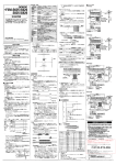
LOCATION OF MAJOR COMPONENTS
I!
11
11
I
}
C)'--+---J;"+------+-h..-----__
H~--O
1.
3.
Upper Basket Feed Pipe
Door Solenoid
2.
4.
Door Microswitch
Electronic Controller
5.
Load Collector
6.
Push Rod Guide
7.
Door Hinge, Spring & Push Rod
8.
Pressure Switch
9.
Wash Motor Capacitor
10. Overfill Spillway
11. Overfill Chamber, Cup & Microswitch Assy. 12.
13. Heater Relay
14.
Drain Pump
IS. Overtemperature Thermostat
16.
Detergent Pump
17. Wash Motor Pump
18.
Heating Element - 2000 Watt
19. Water Inlet Solenoid Valve
21. Detergent Dispenser
20.
Heating Element - 1200 Watt
- 11
Sump
SERVICE INSTRUCTIONS
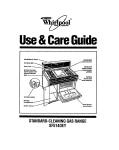
The diagram below illustrates the water flow and identifies the main components in a 3
level micro-filtration system. Notc that the sump is drawn in dotted lines for illustration
purposes.
I.
Water inlet Sulenoid Valve
2.
Collector
3.
Pressure Switch
4.
Sump
5.
Wash Pump water inlet via sump
6.
Washl~,.;
7.
Wash Pump to Upper Spray Arm
8.
Wash Pump to Lower Spray Arm
9.
Various Lower Spray Arm water jets.
10. Lower Spray Arm water jets
11.
Spray Jet Diverter
12. Drain Pump water inlct
13.
Drain Pump
14. Water outlet to drain
- 12
.~;::;
SERVICE INSTRUCTIONS
SPECIFICAnONS
DIMENSIONS OF UTENSIL WASHER
"[\1" Model
Width in mm
Height in mm
Depth in mm
Electric Mains
Current Rating
Wash Pump Motor
Drain Pump Motor
Walcr Heating Elements
Water Volume, per fill
Inlet Water Pressure
Inlet Water Temperature
Drain Hosc
600
825
590
"L" Model
600
1310
590
240 Volt, 50 Hz AC.
15 Amps
II0Watts
30 Watts
2000 Watts & 1200 Watts
6 Litres
30 kP" min. - 1 100 kPa max.
bOoe min - 75°e max
19mm LO.
Wash MotorIPump Assembly
Part Number 8905-'JOO (2 outlet)
Motor Manufacturer - Webster Manufacturing Ltd.
MotorCatNo D63V3110
240V AC, 50 Hz, I PR 0.89A
IIOW. MCR CS&R, 2850rpm.
Class 130
Capacitor 6nF 400V
Warning; Motor is fitted with internal auto reset overload and
may restart without warning.
Resistance of winding @ 20°C i 5%
Hrown & Hluc - 29.0 Ohms.
Blue & Black - 29 0 Ohms.
Black & Brown - 58 Ohms
I\ote:
MotorlPump Assembly, part number ~<)05-900, has pump cove,
with the two IOmm diameter spigots blanked off(2 outlets)
- 13
SERVICE INSTRUCTIONS
Water Inlet Valve
Manufacturer - Eltek
Operating Supply Pressure Range -Static Cold: 20 kPa minimum
1000 kPa maximum
20 kPa minimum
Static I [at
500 kPa maximum
Maximum inlet supply water temperature - 65°C.
Nominal delivery flow rate from valve - 4 litres/minute.
220/240V AC, 50 Hz.
Solenoid DC resistance@ 20"C - 3.94 k Ohms ± 5%
Inlet thread G 3/4" (314'" BSP)
Electrical connection - 2 .x 61mm x 0 8nun QC tabs
Powder Detergent Dispenser
Manufacturer - Elbi, Type 542.
Single solenoid type with gravity latch/lock mechanism
220/240V AC, 50 Hz.
Resistance of solenoid coil 0) :'o"e - J.3 O/un' ± 10%
Total capacity of detergent chamber - 37cc
Fluid Detergent Dispenser
2 Litre capacity with 12 Volt DC pump for 40cc
detergent
injection
,
Optical eye action filler cap for detergent level.
'
Water Heating Elements
240 VAC, 50 ITz, 2000W & 240V AC, SO Hz, 1200 Watt
3 I Ohms 3 @ 20°C (2000W)
Insulation resistance - 20 meg Ohms (minimum).
Flcment sheath material- 321 stainless steel
Mounting - stainless steel (type 302)
Flange and stud - M6 stainless stccl (type 302-3(4)
Ends of sheath scaled with epoxy-cpirez 324A
Electrical connection - 6.3mm QC male stainless steel (type 302-304)
spade terminals.
- 14
SERVICE INSTRUCTIONS
Thermostat - Overtemp
Identitication - Green Dot.
Mounting - M4 x 0.7 male thread
Electrical connection - 6.3mm x 0.8mm QC tabs.
125V/250V
Temperature specitication - Closc. 50 c C ± 4°C
- Open: sOGe :+:3 0 ( ' .
Pressure Switch
Main Contact Load - 16A, 240V AC
Contacts
- Nos. I & 3 utilised t(Jr heater.
- Nos I & 2 utilised for hot & cold watervalves
Electrical connection - 6.3mm male tabs
Nominal Calibration - set 60rnm H:<0
- reset 15mm !i.()
Operating Temperature - T85°C maximum
Drain Pump
Manufacturer - PIaset.
Rated Input - 30W, o 25A, 240V AC
Resistance of Field Winding @ 20°C - 166 Ohms ± 10%
Insulation - Class F
Nominal RPM - 3000, 2 pole motor
Motor temperature protector field winding - 170°C tlips open
Outlet Spigot equipped with non-return flap valve.
Nominal Discharge Rate - 15.20 litres/min @ 1 metre head.
Micro Switch - Overfill
Manufacturer - HoneywelL
250V AC, 20A, UL approved
85°C maximum temperature.
Switch Mode - SPDT.
Contacts - Silver CAD oxide or silver contacts.
Electrical connection - 6 3mm x 0.8mm silver plated QC tabs
Operating Force - 70 gram
Release Force - 10 gram.
- 15
SERVICE INSTRUCTIONS
Mains Terminal Block
Supplier - Multi Contacts Australia Pty. Lld
Poles - 3 marked A, N & E
380Y, 161\ trom 3 x 0.75 to 5 x 1.5mm
Housing - Self Extinguishing Black polyamide
Temperature Rating - 125°C.
Metal Parts - Zinc Passivated Steel.
Heating Relay
MB2240Y 13 Amp.
MB2 POT 13 Amp.
12 Volt Transformer
Arlec part number PS699
Multi-Voltage Transformer
240Y 50 Hz 3-3-12V 500 mA
Operated at 12 Volts DC
Wash Motor Capacitor
400V AC, 50 Hz 6~F
Type - metallised Polypropylene
Electrical Connection - 2 x 6.3mm x 0.8mm QC tabs
Door Solenoid
Manufacturer - ITC
Number 16 - 240V continuolls.
Door Microswitch
Zippy - 10 Amp 250Y
- 16
SERVICE INSTRUCTIONS
ELECTRONIC CONTROL TEST FACILITY
1.
LED Display Test
This test is useful for checking that all LED's are working.
Press the following buttons.
Ist Press Temp SODC, 2nd Power on, 3rd Temp 65°C, 4th Temp sODe
and then Power 011.
All the lights will go on and then one at the time to show that they arc working.
To cancel this mode, Switch off at elcctric supply and switch on again.
2.
Individual Output Control
This allows each output to be operated independently for fault finding.
1st Press Temp SO°C, 2nd Power on, 3rd Temp 65°C, 4th Temp sooe
and then Completed.
Then each contra! switch operates an output as follows.
•
•
•
I
il
•
•
•
•
Completed
Temp sooe
Temp 65°C
Fault
Power On
Operate - Start Blank (at the end)
Operates
"
Wash Pump
Drain Pump
Water Heater
Detergent Dispenser
Door Lock
Cold Water FiJI Valve
Hot Water Fill Valve
To disable this facility and return to normal operation, switch ofI' at electric supply and
switch on again.
"""''"'''-'- - - - -
- 17
Operation
8
9
la
11
1st Hot Rinse
(Rinse LED on)
2nd Hot lZinse
Final I.FD on
Last Rinse
- Cold
(Rinse LED on)
12
13
14
15
]6
17
18
19
20
2J
.,...,
-~
COMPLETED
1.20 min
Cold Fill and wash full signal.
After 15 seconds, wash motor off
fClr 3 seconds, then on again.
Wash.
Drain until empty i 15 sec.
Hot fill and wash until tull signal
After 15 sec wash motor off, for
3 seconds then on again.
Wash
Drain until empty + J5 sec.
Hot fill and wash until full signal.
After 15 sec. wash motor off for
J seconds. Then wash starts again
together with start of detergent disp.
Wash. Heat & Detergent release (5 sec)
Till Hot
2 min
Empty ~ 15"
Till Full
Wash. Heat until 55°C is reached.
Wash.
Drain until empty + 15 sec.
!lot fill and Wash until full signal
After 15 seconds, wash motor off [CH
3 seconds. then on again.
Till Hot
Wash & Heat until 55°C is reached.
I min.
Wash.
Empty + J 5" Drain until empty + 15 seconds
Till Full
Hot fill & Wash until fllll signal
After 15 seconds, wash motor off
for 3 seconds. then on again
Till Hot
Wash & Heat until 82°C is reached
5 mins
Wash and maintain 82°C temperature
Empty + 15" Drain until empty + 15 seconds
Till Full
Cold fill & Wash until full signal
After 15 seconds. wash motor off
for 3 seconds, then on again.
45 seconds
Wash
Empty' 15" Drain until empty ~ 15 seconds.
2J
24
25
End of cycle. Door is unlocked.
buzzer sounds, Completed LED
is lit.
- 18
I:
"
§IRING DIAGRAM L & M MODELS
1--
SERIES 2000-MK2
--d===- _,
.----------,
'--
3--
: DISP'.A'/ BOA";:'
I
L --L...
_
-----
j
---- --
'"
::i: J0
I
;,
P>'OC"
"I
X
=i
r,
----'2+
---I
----
1
Z
...
r-
0
~-
r-
P
-t-_-n/
~"T"~
r,'d
'-:-=.-~
i.--J
08
n
r,
r.
z.
I
...
j
1
~I O!'MP,111-Jl~ , Il~----I
: ,s, H:~71 i ~II'
'~r"
1
Ji
1
CAP.
I
i
_ _ _ _---.r--_
:'\iASH'.,
LX,'( u";j
" 't ."'l-!
~w
'~'!
T
i
'
---~~t.,.-1C-A~2CR_
~!
-
"
! I! :.
I
,
i
.
I
I
~:)C~ n_!_
1
1
j
i
,
L.::-:c
-.~LAr::.T'·
--lE
~/;c-:-:-,
,,;F. '.::: f".'
- 19
:-JNI~=.·7::Y-;5 A;::" ,:':JT
·1. )e.t
1
4
SERVICE INSTRUCTIONS
TROUBLE SHOOTING GUIDE
1.
Poor Wash
Most poor wash problems are caused by insufficient water supply to the spray
arms.
Clear any obstruction from the spray arms. Check cleanliness of the wash
filters.
Check the upper spray arm nozzle for any blockage Top spray arms only have
jet holes on the top and a small drain hole on the underside.
Use a clear glass or plastic panel the size of the door opening to allow a
view of the spray anns in operation.
cle~r
Check top basket venturi cone lines up with delivery nozzle in top of tub
BOTTOM SPRAY AR~, jets should easily reach top of the liner, with
substantial force when empty.
TOP SPRAY ARM, during this test cover bottom basket area with heavy
dishes or pans. Jets from top spray arm should easily and forcefully reach the
top of the liner.
If spray height is correct, check rotation of spray arms, the range is 20-36
R.P.M.
Spray patterns should be clearly defined streams of water. (Not diffused. This
indicates obstruction in spinner am.
2.
Bottom Spray Arm (poor performance andJor low pressure)
Check water level in the Utensil Washer. Low water level will cause poor
wash perfomance and pulsing/hunting of spray am pressure. Allow machine
to till three times and check each fill. Compare water level in tub with
min.- max. marking on lower spray ann support, (see sketch) if water level is
not correct refer to pressure switch adjustment Low water level may be due
to syphoning. Check drain hose routing.
Water leveJ indicators
~
Max.imum level
FiI
'-
..
~
-~~
" : -~~:'"c 'j
- iW
Minimum level
SERVICE INSTRUCTIONS
TROUBLE SHOOTING GUIDE (Cont'd)
IMPORTANT It is essential that the discharge end of the drain hose
terminates not lowcr than 600mm from the top oflhe Utensil Washer.
Cbeck drain hose for kinks, sharp bends ctc
If the water level or volume is too low or inconsistent then check the pressure
switch and replace if necessarv.
Check the inlet hose to see thal it is free of kinks and sharp bends. Also check
tilters and supply pressure.
3.
Top Spray Arm
4.
Rotation of Spray Arms
(poor performance and/or pressure)
Upper Spray Arm feed hose, check tbat thc hose is not kinked, blocked or
pinched.
Check free rotation of the arm by flicking it with the hand. If the arm turns
slowly during actual opcration check that it is horizontal and not binding on tbc
shaft
Tbe spinner must have slight up/down clearance
Spray pattern, check jets for blockages. Replace arm if necessary
5.
Drain Time
Check that unit drains in the allocated time. Ifnot look for drain hose damage
or obstmctions to flow.
6.
Water in Machine
Residual water in the machine after it should have drained, may be caused by
•
Drain hose strained to reach the spigot on the sink waste and subsequently
flattencd (especially when hot)
•
The spigot on the sink waste not drilled out completely and deblis has collected
and partially blocked the spigot.
•
Hose extended beyond allowable limits.
•
Hose kinked.
•
Hose incorrectly extended by using a smaller diameter hose as the e:\1ension
pIece
- 21
SERVICE INSTRUCTIONS
TROUBLE SHOOTING GUIDE (Conrd)
7.
Motor Cutting Out
Give unit an extended run in a fully installed condition and ensure that motor does not
out during this time. Ensure that machine is up to operating temperature
8.
Machine Will Not Start
Make sure that the door is closed, press door until it clicks shut
Make sure the "Power On" light is on, if not, check the power supply to the mac:hine
When power is available to machinc. switch power point ofT and then on
Check membrane switch
9.
Machine Starts, But Water Does Not Enter Machine
Check
Check
Check
Chcck
10.
that the water taps are on
for kinks and sharp bends in hoses
inlet filters in supply hoses
coil of watervalves.
Programme Is Not Advancing Automatically
This may bc duc to water loss caused by syphoning. The machine
will st ay in the heating mode.
Check height of discharge er;d of drain hose, this should not be
lower than 600mm from the top ofthc Utensil Washer.
Check Thermistor position and supply to heating elements
11.
Water Does Not Empty Out of Machine
Check drain hose for kinks and sharp bends.
Check drain filter for blockage
[f thc machine pumps water into a bucket when (he drainhose
is disconnected from the waste pipe, then the waste pipe plumbing
is blocked.
Chcck drain pump for blockage and operation
12.
"Fault" LED Flashing
Check hot inlet water temperature for 60°C min.
Check Thennistor position
Check operation of heating elements.
- 22
Cllt
[I,I
I,
I
I,
REMOVAL OF PARTS
OUTER DOOR PANEL
SECTION 1.
Disconnect electrical power supply
Open the door to the horizontal position
and remove the three Phillips head stainless
steel screws fitted to each side of the door
to enable the Outer Door Panel to be
withdrawn from the stainless steel door liner.
Whilst removing the six stainless steel screws,
ensure the Outer Door Panel is supported to
prevent damage. It is suggested to leave one
central screw loose and in place for support
whilst removing the three stainless steel screws
on the other side of the door.
To remove the Outer Door Panel, support the
side with all three screws removed with your knee
under the Outer Door Panel while holding the Outer
Door Panel and stainless steel door liner together
on the opposite side with your free hand and remove
the remaining central screw.
Carefully lift the Outer Door Panel clear, carry out
any work required. Re-fit the Outer Door Panel.
- 23
11.
REMOVAL OF PARTS
SECTION 2
DETERGENT DISPENSER
Disconnect electrical power supply
Remove the Outer Door Panel.
Remove the six retaining screws which fix the
Detergent & Rinse Aid Dispenser to stainless •
steel door liner through upper and lower fixing .
brackets. On electronic models, attached to the\"1---~~~~
right hand corner of the upper fixing bracket by
.
.~-.....,
one of the retaining screws, is the Thermistor
Retaining Clip.
Remove the Detergent & Rinse Aid Dispenser
from the stainless steel door liner
Upon refItment of a Detergent & Rinse Aid
Dispenser to the stainless steel door liner ensure
the sealing face area is clean and free from
damage. To ensure an effective seal between the
Dispenser seal and the stainless steel door liner
face, alternatively tension the two centre screws
through the upper and lower brackets and then
the upper and lower corner screws.
Operate & test machine before leaving.
Note: The Dispenser upper & lower fIxing bracket also clamp the thermistor bracket,
insert thermistor in bracket before tightening screws. Refit Outer Door Panel.
- 24
REMOVAL OF PARTS
CONTROL PANEL
SECTION 3
Disconnect electrical power supply
Remove the Outer Door Panel
(Section I)
Rcmove the Six Phillips Head countersunk
stainless steel screws located at the top
section of the stainless steel door liner.
Four screws are located on the top of the
liner flange and a screw on each side is 80mm
from the top corner.
Close door, pull control panel assembly forward
Carry out work required. If the Control Panel is unserviceable remove the components
and assemble them onto a new Control Panel.
Before reassembly on to the top of the door ensure that the reinforcing channel is in its
correct position, otherwise it could be very difficult to reopen the door.
Refit Control Panel. Ensure door handle operates correctly and locking hook latches
securely.
Refit Outer Door Panel.
- 25
REMOVAL OF PARTS
SECTION 4
MEMBRANE SWITCH
Replacement of Membrane Switch
Remove Outer Door Panel and Control Panel. Section I & 3.
Removal of the membrane switch can be done without removing the power/control
board. Remove the membrane switch tail from the board connector by unlatching the
patent tail connector. (See sketch.) Remove the touch-control as follows. Insert the
blade of a knife or small screwdriver under the extreme left hand corner of the
membrane assembly and prise it from the Control Panel. When sufficiently removed to
grip with tweezers or fingernails gently pull the adhesive backed assembly off the panel
for the full width of the membrane. Grip the extreme end and remove.
Finger Grip
Film Switch
~
Slide top
part to
unlatch.
Replacing the Membrane Switch
Clean the switch area of the Control Panel front with a clean cloth using methylated
spirit. Any gum adhering to the board will not be dissolved by methylated spirit, but it
can be rolled up into itselflike dough and it departs cleanly from the Control Panel.
Starting at the left hand end of the mcmbrane switch facing the front of the panel,
lightly align the membrane assembly at the left end, butting it against the plastic
moulding of the handle opening. Lay the ribbon/membrane assembly down when half
way along, feed the tail through the slot in RHS end. After checking for correct
positioning gently press the assembly down to adhere firnlly.
- 26
1I
I
I
REMOVAL OF PARTS
I
I
CONTROL BOARD
SECTION 5
Replacement of Power Control Board
Remove Outer Door Panel and Control Panel Section 1 &3.
Removal
Disconnect the film switch from the cormector. (See sketch)
Remove 3 circuit board mount screws
Lift PCB and place in front of control panel.
Remove dew protection and carefully disengage the LED sub-board which is
cormected to the PCa.
Replacing the P.C. Board
Placing the Control Panel upside down on a bench, placc the board and LED
sub-board cormected to it, near the switch end. Carefully insert the LED board into
position while holding the plastic clips up alternately with a thumb. ENSURE THE
LED'S AREN'T DAMAGED WHEN SLIDING THE BOARD INTO POSITION.
The LED'S should now be in the centre of' the control board holes provided for them.
Place the main board in position and secure with the 3 screws.
LED CirCuit
Ribbon Cable
Board Mount
Clips. (2 c7 ips)
LHandle
/
LED
!~ft Cl ip
l~
LED Bezel
Panel
- 27
I',
I'
REMOVAL OF PARTS
I
I
il
SECTION 6
DOOR SAFETY SWITCH
Replacing the Door Safety Switch
Remove Outer Door Panel and Control Panel. (Section 1 & 3)
Remove clip retaining microswitch assembly (Sec sketch), and pivot thc assembly to
clear the retaining lug of the black plastic moulding.
Withdraw the switch from the mounting spigot by pulling forward.
Remove the rubber cover and pull quick-connects off switch tenninals.
Assemble in reverse order.
I
~:~;1 \"i
<ch
,
Cl i P
-Micro Switch
~jaunt Spigot
i cra Switch
ontact Point
~Iicro
Switch
(to remove
pull switch out)
Micro Switch Cover
(to remove or
replace, angle the
assembly and remove
from spigot).
Micro
Mount
- 28
REMOVAL OF PARTS
EXTERIOR PANELS "M" MODEL
Disconnect electrical power supply
To remove the exterior panels the following sequence should be observed.
Top Panel:
Remove 2 screws located underneath the front ledge and remove 2
screws located at the back Oange
Bottom Panel:
Remove 2 screws located on each side of the bottom panel
Back Panel: Remove 6 screws located on the back oCthe machine
Side Panel LH & RH:
Remove 2 screws located on the front flange and remove 2
screws located on tbe back flange
Assemble in reverse order
EXTERIOR PANELS "L" MODEL
Disconnect electrical power supply
Top Panel:
This panel is removed as dese.ibed lor the
""]\1"
Model.
Lower Door: Remove 4 screws securing the 2 hinges of the door to the frame.
Back Panel Upper:
Remove 6 screws located on the back of the machine
Back Panel Lower:
Remove 4 screws located on the back of the machine.
Side Panel LH & RH: Remove 3 screws located on the Iront flange and remove::;
screws located on the back flange
Assemble in reverse order.
- 29
I:
I!
:1
I:
REMOVAL OF PARTS
:1
I
Stainless Steel Door Liner
The stainles steel Door Liner is retained to the machine hinges located at the base of
the stainless steel Tub. Two stainless stcel Phillips head countersunk screws on each
side of the lower section of the stainless steel Door Liner Flange, clamp the Door Liner
to the Swing Arm (movable arm) of the hinges.
The Fixed Arms of the hinge assembly are screwed to the front flange of stainless steel
Tub by two stainless steel countersunk Phillips head screws, identical to the screws
used on the Swing Arms of the Hinges. It is advised to remove both Push Rod Springs
prior to removal of the stainless steel Door Liner from the dishwasher.
Disconnect electrical power
Remove Outer Door Panel
Remove the Door Hinge Springs and Push
Rod Guides
Remove the four stainless steel Phillips head
countersunk screws from the side flanges
with the door in the open position, as shown
right.
Return the door to a partially closed position
as shown in the photograph below right to
prevent damage to the spillway fixed to the
front lip of the stainless steel tub.
With the Swing Arms of the door hinges
returned to the door Open position, lift the
stainless steel door liner clear of the
machine as shown below right.
-.
----"'i
Remove 2 scrcws
from each sidc.
Reassemble the machine in reverse order.
Moyc Door
Liner to Ilcar
dosed position.
- 30
REMOVAL OF PARTS
DOOR HINGE, SPRING & PUSH ROD GUIDES
Disconnect electrical power supply.
Remove Top and Side panels to expose the door
hinge system. The complete door assembly is
counter balanced with a compression spring
system mounted at cach side of the machine.
A Push Rod is connected to the Swing Arm
of the hinge plate forming a lower pivot point
The upper cnd of the Push Rod is supported
by the Fixed Guide which is anchored to
the chassis rail by two retainer clips.
Upon opening the door the Push Rod will
pass through the bore of the Fixed Guide,
decreasing the length of the Push Rod
between the step and Fixed Guide.
Hence the compression spring located on
the Push Rod will be compressed by the
reduction oflength between the step
of the Push Rod and the Fixed Guide.
Closing the door will result in an increase of length
between the step of the push rod and the fixed guide,
resulting in a reduction of the spring tension.
To remove the Push Rod and Fixed Guide, close the door and
push the Fixed Guide downwards to unlatch the two retainer
lug clips, whilst pulling the bottom of the Fixed Guide away
from the Chassis Rail.
Upon removing the Fixed Guide from the Chassis Rail slots,
t,he Push Rod and Door Spring can be disconnected from the
Swing Arm of the Hinge Plate by tilting the Push Rod
outwards to disengage the offset keeperlretainer.
Reassemble in reverse order.
- 31
REMOVAL OF PARTS
DOOR HINGES
Disconnect electrical power supply
The Door Hinges consist of a left hand and right hand hinge assembly. The fixed arm is
mounted to the flange of the stainless steel tub by two stainless steel countersunk screws,
whilst the swing arm or movable arm is attached to the stainless steel door liner flange with
lwo stainless sleel countersunk screws. A positive slop position is provided wilh the door
in the open position by the swing arm locating on a heavy projection formed on the fIxed
ann of the hinge.
To replace the Door Hinges, the stainless steel door liner needs to be removed.
Remove the two stainless steel screws which clamp the fixed ann to the flange of the
stainless steel tub.
Repeat procedure for the opposite side.
Replacement hinges can be fitted by reversing the procedure.
Reassemble in reverse order.
Operate & Test machine before leaving.
/
Hinge Fixed Arm
Hinge Swing Arm
- 32
/
REMOVAL OF PARTS
Upper Basket Rail & Wheel Guides
On each side wall surface of the stainless steel tub is
mounted a heavy gauge stainless steel Rail Guide, which
is free to slide forwards and backwards, when the top basket
is pulled out to 10adJunload. The two Rail Guides support the
top basket by means ofa set of wheels attached to the top basket,
which engage the top and lower surfaces of the Rail Guide.
Each Rail Guide is supported by two Wheel Guides located on
each side of the stainless steel tub wall surfaces, which support
and allows each Rail Guide to slide freely.
Each Wheel Guide has a stainless steel axle which is threaded
into a heavy gauge support plate, affixed to the external surface
of the stainless steel tub, by a stainless stecl Phillips head screw
clamped to each vertical chassis rail with a MS nyloc nut.
Each stainless stecl Phillips headed axle is located within the
two vertical side recesses of the stainless steel tub, which
spans the complete height of the stainless steel tub walls.
As the support plate is attached to the vertical chassis rail it
remains captive even ifboth Wheel Guide Axles are removed
together. Previous model machines required only one Wheel
Guide to be removed at a time, as the support plate was only
supported by the two Wheel Guides.
To remove the Rail and Wheel Guides proceed
as follows:
Remove both front Rail Guide Pegs by
compressing the top sections together and lifting
clear from the Rail Guides as above right.
Slide the top basket out and clear of the Rail Guides
Remove both Rear Rail Guide Pegs from the Rail
Guides and lift clear.
Slide the Rail Guides out and clear from the
Wheel Guides.
Remove the Wheel Guide Axles by releasing
and unscrcwing with a Phillips screwdriver
as shown above right.
Ensure the stainless steel cup washer, which
houses the rubber "0" ring, is identified with
the recess side of the washcr to the surface
of the stainless steel tub.
"",'heel Guide
Axle
~
\X'heel Guide
Refer to illustration right for the correct
assembly of the Wheel Guide Axle. Wheel
Guide, stainless steel cup washer and rubber
'<0"ring.
Reassemble in reverse order.
Operate & test machine before leaving.
- 33
Peg
a
p
..,j~~!~"""d[;j~:::=~~~fJIl
__--llrr
lIJff:'~E;':::-Q
Rail Guide
REMOVAL OF PARTS
Tub Gasket
The tub gasket is of a new design wherein the left hand and
right hand gasket extensions (as used in previous models) is
now attached to the tub gaskct
To rcmove the tub gasket, grasp the bottom
section and pull the tub gasket from thc rccess
formed in the stainless steel tub as shown right.
When rcfitting tub gasket to the stainless stcel tub
recess, bcgin by positioning both ends of the tub
gasket into the bottom of the stainless steel tub
recess which is formed around the tub by a
flange located 8 mm from sides and top of tub.
The tub gasket has a moulded scction on each
end in the form of a lip, which locates under the
inner side of the stainlcss steel tub recess flange.
Ensure the lip is correctly fitted to the recess on
each end of the tub gasket.
With both ends of the tub gasket positively
positioned in the recess, press down onto the block moulded section of the tub gasket at
one end to maintain its position and commence to fced the tub gasket into the recess.
The tub gasket has three barbs moulded into the side face of the gasket and extends the full
length of the tub gasket. As the tub gasket is pushed into the recess the barbed side face
of the tub gasket engages with the side face of the recess flange.
The tub gasket is located within the recess by fIngcr pressure only, do not push the gasket
"upwards" as this will tend to stretch the tub gasket and cause an excess in length to
occur, resulting in the tub gasket not seating correctly.
After approximately 300mm of the tub gasket has been seated into the recess, switch to
the opposite side of the machine,
press down onto the block moulded
section of the tub gasket to maintain its
position at the bottom of the tub and feed
the tub gasket into the recess by finger
,
pressure.
After seating approximately 300mm of tub
gasket into the recess, switch to other side
of machine and repeat the procedure.
Alternate procedure
Scat 300 mm of Tub Gasket at a
until both sides of
time, switching from side to side.--_!
the tub gasket has been inserted and seated correctly.
Starting at each top corner seat the gasket into the
radius of the stainless steel tub, alternated from side to
side ensuring it is seated/located correctly.
Finally, seat the tub gasket working from each side
across the top section of stainless steel tub, with
central section also to be located into recess correctly
without an excess in length of tub gasket present
Operate & Test machine before leaving.
----
- 34
I
/
!
REMOVAL OF PARTS
Pressure Switch &Adjustment for Waterlevel
The Pressure Switch is located on the right hand iront chassis
rail, directly to the rear of the electrical access panel, as shown
right. To remove the pressure switch proceed as follows:
Disconnect Electrical Power Supply
Remove appropriate panels
Locate the pressure switch squarc detent spring
mounting on the bracket attached to thc front
chassis rail as shown below right.
Compress the detent spring mounting with a pair
of pointed nose pliers as shown below, push the
mounting through the square hole in the bracket to
release the Pressure Switch.
Compress the double coil hose clamp located on
the pressure switch hose with pliers and slide hose
clamp off the pressure switch spigot.
Grasp the Pressure Switch and pull the hose from
the Pressure Switch.
Remove the 6.3mm terminals and wires from the
pressure switch tab connections.
Replace pressure switch if faulty.
Adjust Pressure Switch for Waterlevel
To adjust Pressure Switch for Waterlevel proceed
as folIows:
On the back of the pressure switch is a central spigot which house the adjustment screw for
waterlcvel
Turning this screw clockwise raises the level and anti-clockwise lowers the level.
It is recommended, to make the adjustment, turning the screw no more than one half tum at the
one time and then check the result.
Reassemble in reverse order.
Operate & Test machine before leaving.
Compress -i.~
Detent.
- 35
REMOVAL OF PARTS
Sump
The Sump is located under the stainless steel tub and is attached to the tub by a Sump
Gasket and a Sump Retainer fitted to the interior of the stainless steel tub. The Sump
Retainer locates into the recessed apelture in the base of the stainless steel tub and into the
internal face of the Sump. The Sump, Sump Retainer and the recessed aperture (190mm
diameter) have an 80mm long flat section towards the front of the machine and is parallel
with the front lip of the stainless steel tub.
On the flange formed on the recessed aperture in the stainless steel tub is mounted a
grooved sump gasket, which is compressed between the sump flange and the sump retainer
by four mounting screws.
Disconnect electrical power supply
Remove appropriate panels.
To remove the Sump, disconnect hoses attached
to the Sump Spigots.
Remove Phillips head screw whieh retains the
Drain Pump to the sump socket.
Remove the four mounting screws and lift the
Sump Retainer clear as shown right
Remove Sump from the stainless steel tub
and lift it clear from the stainless steel tub
as shown below left.
Remove the Sump Gasket from the flange
of the stainless steel tub as shown below
right
Remove Sump RctJ.Ln<:r.
sA;
:-.
Reassemble the machine in reverse order.
Operate & test machine before leaving.
- 36
)
,(
REMOVAL OF PARTS
Wash Motor/Pump Assembly - Removal and Refitting
The Wash MotorlPump Assembly is a high efficiency compact devise horizontally
mounted at a 30° angle to the rear rail and located within the rear left hand corner of the
machine as shown right. A centrally positioned induction or inlet spigot on the pump
cover also provides the front mounting via a short hose connected to the sump spigot with
j
appropriate hose clamps.
To remove the Wash Motor/Pump Assembly
from the machine proceed as follows:
Disconnect electrical power
Remove appropriate panels.
Disconnect the four pin wash motor/pump
receptacle from wiring harness/plug as shown
above right.
Remove the two pump outlet hoses ti·om the
pump cover by compressing the double coil hose
clamps and sliding the clamps and sliding the clamps
along the hoses away from the pump cover spigots,
The two hoses as shown above right are
identified as follows: _
Short hose connection
between pump inle<
,p;got and ,ump ,pigot.
DiM:onncd
four pill
n::ccptaclc.
Upper hose - 22mm diameter pump spigot parallel with the base of the stainless steel
tub. Function:- Water supply to Top Spray Arm.
• Lower Hose - 2Smm diameter pump cover spigot - hose connector. Function: - Water
supply to Lower Spray Aml.
Move double coil hose clamp
Grasp each hose in turn and disconnect
::lway from Wash Pump/Motor.
from the pump cover spigots.
Removal of the two outlet hoses now
provides access to the centrally mounted
induction/inlet spigot of the pump cover.
Compress the double coil hose clamp
located on the inlet hose and slide clamp from
spigot towards the Sump as shown left.
Note: The Wash Motor/Pump is actually
supported by the short hose hetween the
Wash Motor/Pump and the corresponding
spigot of the Sump.
•
~.
Chasl>is I look
- 37
REMOVAL OF PARTS
Wash Motor/Pump Assembly - Removal and Refitting (Cont'd)
The rear end of the Wash Motor is supported by a triangular detachable neoprene
Mounting Support Strap, which is attached to a hook located on the left hand rear chassis
panel. On the rear diecast end-shield oflhe Wash Motor are the support hooks onto
which the two lower holes of the triangular Mounting Support Strap are attached to
support the Wash Motor. Refer to the previous photo which has the rubber triangular
Mounting Support Strap removed to clearly show the hooks.
Two options are available to remove the Wash Motor triangular neoprene Mounting
Support Strap:
Twist the Mounting Support Strap and push the
locating hole from the front hook on the Wash
Motor end-shield as shown right. Push the
Mounting Support Strap up and release the
Mounting Support Strap from the hook
located on the chassis panel. The rear
locating hole of the mounting support strap
can then be disengaged from the hook on the
wash motor end-shield. The wash motor
mounting support strap can then be lined clear
of the machine.
OR
Remove the retaining screw which mounts the
hook onto the chassis panel. Detach both
locating holes in the Mounting Support Strap from both hooks on the Wash Motor
end-shield. Lift clear the Mounting Support Strap and the detached chassis hook from the
appliance.
The Wash MotorlPump can then
be withdrawn from the pump
cover inlet hose, as shown
below right, and lifted clear as a
complcte assembly.
Refit the Wash Motor/Pump and
reassemble the machine in
reverse order or refer to section
Wash MotorlPump requires to be
dismantled.
Operate & Test machine before
leaving.
- 38
REMOVAL OF PARTS
I
Wash Motor/Pump - Dismantle
11
!
Sit the Wash MotorlPump upon the rear diecast end-shield on a table or suitable flat
surface. Whilst viewing the Wash MotorlPump assembly from the pump cover end.
position the two support hooks formed on the diecast end shield at a twclve o'clock
position. It should be noted the pump outlet spigot for the water supply to the Upper
Spray Arm is at the nine o'clock position, whilst the pump outlet spigot for the lower
spray arm is at the four o'clock position. The alignment of the pump cover to the two
support hooks on the diecast end-shicld of the motor must be maintained for correct
fitment of the Wash Motor/Pump to the machine
Directly below the pump outlet spigot located at the four o'clock position (Lower Spray
Arm water supply) on the outer diameter, is a 3 mm diameter round spigot, engaged into a
slot on a corresponding black plastic flange, which is known as the Pump Plate.
Locate the small locating spigot and corresponding cutout (3mm wide) and mark this
location onto the diccast f1anged end-shield of the Wash Motor (four o'clock position)
with a felt tipped marking pen for re-assembly purposes. It can also be noted that the four
o'clock position is identified by the electrical input cables entering the slalor at this
position.
Release and remove the four Phillips head screws which retain the pump cover to the
Pump Plate and wash motor f1anged diecast end-shield.
Lift clear the pump cover and the neoprene "0" ring which seals the pump cover to the
pump plate.
The pump impellor requires to be removed to access the removal of the Pump Plate.
To remove the impellor from the shaft, insert a screw driver into the opposite end diecast
end-shield air cooling vents and engage with a blade of the cooling fan (eight diecast
blades on rotor), to lock the rotor in a stationary position. Whilst holding the screw driver
tirmly, grasp the impellor and turn in an anti-clockwise direction to unscrew the impellor
from the shaft. Lift impellor clear from the pump shaft.
The f1anged pump plate which houses the carbon faced rotary seal and bellows can also be
lifted clear from the Wash Motor.
Upon lifting the Pump Plate clear, the f1anged diecast end-shield of the Wash Motor will
be visible. A black plastic water slinger is attached to the motor shaft, which is housed by
an annular projection with a cutout at the six o'clock position, to allow water leaking past
the rotary seal to exit the f1anged diecast end-shield.
Refer to re-assembly section of Wash Pump.
Screwdriver insencd intu cooling
vents/blades [0 lock shaft,
- 39
REMOVAL OF PARTS
Wash Motor/Pump - Reassemble
Position the Wash Motor with the two mounting hooks at the twelve o'clock position and
the input electrical cables in a corresponding four o'clock position. Ensure the motor is
electrically sound and the bearings are not water damaged/noisy.
The Pump Plate is normally supplied as a replacement with the bellows and carbon faced
seal factory fitted On the underface of the Pump Plate are two cutouts, within the outer
mounting rings, positioned on each side of a mounting hole.
Note: Both cutouts are to provide an exit for water leakage past the rotary seal and
impellor ceramic face. This mounting hole must be positioned directly opposite the two
mounting hooks at the twelve o'clock position. ie: Position the mounting hole and two
cutouts at six o'clock position on the tlanged diecast end-shield of the Wash Motor
Note that the large directional vane for the lower spray arm spigot is then located at the
four o'clock position.
Check the condition of the pump impellor for damage and inspect the ceramic rotary seal
face for condition/damage. If damage/wear is present replace both impellor and pump
cover/rotary seal.
Fit the impellor to the right handed threaded pump shaft. Rotate impellor and compress
rotary bellows/seal until the rotor of the Wash Motor commences to rotate with the
impellor
Insert a screw driver into the opposite end diecast end-shield air cooling vent and lock the
blades of the cooling fan and rotor from turning, whilst screwing the impcllor onto the
shaft at the opposite side of the wash motor/pump. Tighten impellor securely and remove
screw driver from the blades of the cooling fan
Clean and refit neoprene "0" ring to Pump Plate if a replacement is not available. It is
suggested to fit a replacement if a pump is serviced.
Refit the pump cover to the Pump Plate ensuring the 3mm spigot on the pump cover
locates into the cutout (3mm) of the Pump Plate located at the four o'clock position.
Refit the four Phillips headed screws to the pump cover pump plate wash motor mounting
holes. Tighten all four screws evenly, alternate from side to opposite side to ensure the
pump cover and pump plate compresses the neoprene "0" ring correctly.
Insert a finger in to the pump cover inlet spigot, engage with the impellor blades and
establish the impellor/wash motor rotor is free and turns without fouling the pump cover
Refer to removal and refitting section of Wash MotorJPump.
Ceramic Face - - - " : - _
of Impcllo["
- 40
REMOVAL OF PARTS
DRAIN PUMP - REMOVAL
The Drain Pump is a self contained motor and pump assembly mounted directly into the
Sump by the induction or inlet spigot equipped with an neoprene "0" ring to prevent
water leakage. A single Phillips head screw retains the complete motor and pump to the
Sump. Removal of the Drain Pump is accomplished by the following procedurc-
Disconnect electrical power supply
Remove appropriate panels.
Disconnect the two QC temunals and wires from the 6.3mm tabs marked "L&N" mounted
on the encapsulated field windings of the Drain Pump Motor.
Remove the drain hose double coil hose elamp with a pair of multigrips/pliers from the
pump outlet spigot as shown below left and withdraw the moulded drain hose elbow from
the pump outlet spigot. The moulded elbow of the Drain Hose has two offset slots in the
end face of the elbow, which engage with the offset lugs on the pump cover/outlet spigot.
This feature is to index the drain elbow/hose into the correct angle and position in relation
to other internal components.
Remove single Plullips head screw which retains Drain Pump to the sump socket as shown
below right
.~ . ='~~
Grasp the Drain Pump and pull the complete motor and pump assembly from the bore of
the sump socket, wherein the Drain Pump Spigot and neoprene "0" ring is housed as
shown below.
The Neoprene "0" ring is removed from the
pump cover/inlet spigot and discarded. A
replacement neoprene "0" ring should be
used upon refitment of the drain pump.
Refer to refit section of the Drain Pump or
refer to dismantle section of the Drain Pump.
- 41
REMOVAL OF PARTS
Drain Pump - Dismantle & Assemble
As the Drain Pump is a self-clearing devise, generally, the Drain Pump will not require to
be dismantled. However, if there is a necd to dismantle the Drain Pump after having
removed it then follow this procedureRemoval of the Drain Pump covcr/inlet spigot will require a 'Torx" hand driver fitted with
a T-15 drive to rcmove three torx headed screws which retain the pump covcrlinlet spigot
to the pump body/motor assembly. Prior to removing the three torx screws, view the
Drain Pump from the motor end with the two electrical tap terminals marked from left to
right as "N" & "L" and also invcrted. The pump cover outlet spigot (three deep grooves
on surface) is positioned in relation to the electrical terminals "N" & "L" at an eleven
o'clock position. Mark both pump cover and pump body to retain this relationship.
Remove the three torx headed screws and separate the pump cover from the pump body
A Neoprene "0" ring is located within a groove on the pump housing, carefiJlIy remove
the "0" ring, clean the groove and refit the "0" ring.
A flap valve is incorporated within the pump cover/inlet spigot The purpose of the flap
valve is to ensure water from the household drain system will not flow back into the
dishwasher. Located within the cnd groove on the pump cover/outlet spigot is the
retaining ring/flap valve. Lift the retaining ring/flap valve from the groove, clean, examine
for damage and refit to pump cover/outlet spigot groove.
Establish that the domed surface of the flap valve is towards the seat face of the pump
cover/outlet spigot. The retaining ring of the flap valve should be positioned within the
groove, for the domed surface of the flap valve to contact the seat face effectively and be
concentric with the bore of the pump cover/outlet spigot
NOTE: If the flap valve is not seated correctly it will not operate as a non-return valve
Refit the pump cover to the pump body, locating the outlet spigot at the eleven o'clock
position in relation to the electrical terminals "N & L". Press both components together
without damaging the neoprene "0" ring and fit the three torx head screws and tighten
evenly.
Insert finger into pump cover/inlet spigot, engage with the impellor blade and establish
impellor will turn freely.
NOTE: A magnetic effect between rotor and stator will cause the impeIlor to "flick"
past the poles of the motor every 180 0 of rotation. This is normal and the effeet is used to
obtain a sclf clearing pump action.
Refer to refit section of the Drain Pump.
,
- 42
REMOVAL OF PARTS
DRAIN PUMP - REFIT TO MACHINE
Disconnect electrical power supply
[t is recommended to replace the neoprene "0" ring which seals the pump cover/inlet
spigot to the sump socket. Fit neoprene, "0" ring onto pump eoverlinlet spigot and locate
against the eight stops moulded onto the surface of the inlet spigot
When engaging the drain pump inlet spigot to the sump socket, it is advised to smear
water onto the surface of the neoprene "0" ring, to assist entry into the sump socket.
Approximately position the pump cover/outlet spigot towards the front of the machine, or
in a horizontal mode, insert the pump cover/inlet spigot into the sump socket
Exert hand pressure against the drain pump to compress the neoprene "0" ring and rotate
at the same time approximately 90", to seat the slotted locking plate of the Drain Pump
against the retaining boss of the Sump.
Relit the Phillips flange head (two start thread) screw Do not over-tightt>n.
Slide the double coil hose clamp over the drain hose elbow and lit the elbow over the
pump cover/outlet spigot. Engage the two offset slots in the cnd of the drain hose elbow
with the two lugs on the pump cover/outlet spigot
Push the drain hose elbow fimlly onto the two offSet slots and lugs
Compress the double coil hose damp with multigrips/pliers and position clamp on drain
hose elbow between the wash motor/pump and Drain Pump. This position allows access
to refit or remove the double coil hose damp with multigrips/pliers.
Relit the QC Terminals and wires to the Drain Pump tabs marked "N" & "L"
Reassemble in reverse order
Operate & test machine before leaving.
- 43
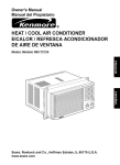
!PARTS LIST - Exterior Panels
---_.~
I
11
I
2
-1
.5
../
12
-3
4
6
9
'0
~e
'5
22/
I
~
~
/-<J~
21
/
23
/6
~
~_17
20
_ _ _ _ _ _ _ _ _J
- 44
PARTS LIST
- - - - -
Price
-
,
I
___---JI
---l
_~-,-------_-----=--==:.c--==~-,-------
--=:::]
_____J
,
i
-~
1
--------j
--~
I
------------1
------------]
.
__
.-
-
- - -
- - ------
-_==-=-=-----------------
'
1
I
--------l
1
I,
l
1
~----
-----------------------------11
----
1--
[
--------
----j
-----~
----------
- 45
IPARTS LIST - Door Components
~
IV-
.0
C')
MW'
t
!i.
co
C\l- ...
,I'L.
-J
- 46
PARTS LIST
DOOR COMPONENTS
1~1t.::...em-"-----_-----'Pa:. :-r.:. .:tN.: . .u:. :-m:.:.:b:. :e.: . .r_-----'D::...:e:..:s.::...crc.:.!ip:..:t-=:io-;;n_-_-_I
1
[ND 001
Outer Door
2_
89058 L
Screw
----'-P.::...ri-=-ce"----_i
I
_~
.~-,I
~
r
l--
~-
-
-'
.....
\"-\-
Door Hinge LI I
-------------=-~--'-'--'--"'-=-=::..:..-
. 7_
I 8
i
-
Door Hinge RH_:::...:.._ _ 851
[67
Screw
- ---890548
Bracket Door- -Cuch
--=--::.=--:..:=-----------="-==
---
9_
890547
10_
'r'r _. ,. ':;)$'4-(;
11.
--·_·~_- _::..:'_)_::'_1_:):..1_ _ Lower Door Seal
Door Latch
Door Liner
_-'--'-~---=--c"-------=-.:..:.:
'-=-=----
_
1-=--------------- ------------------
t:: __ J::;:
~
123 la 32
c
!
33
..
TN
,_"D':'..':0":'0:'.5
S.cre"_Hin",ge:::.-_ _
Screw
n"'ni"'sl_o_I_B_ra~ket..
_ _ _ _ _ _ _ _ ---.J
.
T"h":'e..
8905145
8511896
---
--------
-I
I
---j
- - ----
-
---
----
--I
_ _..J
F-------------- ~--=J
---------
. 47
PARTS LIST -
Wash Tub and Electrical Components
-~---- - - ~ I
'0
\Q
(,-)
,~,
!
]
I
!
\(},
Y
\l'f~
.'
/~
T'
:~«
0
. . . .
~"
*
"I
'"
J
<Y")
~
C\I
I
~
~cv
.
~
{"
G
II)
~
~-
~~
{)
"-
<IJ
C'J
\ .....
N
o-~
-
,
___-I
- 48
EX. VIEW DRAWING 4365
UNER ASSEMBLY
-
~'8
17
21--.,.
....
-
9
10
..
:5~-~
I
'
~
•
'~
3
,
"
8
4
6
7
~:
47
49~50
-.
ge4DW 118
ITEM
I
2
3
4
5
6
7
8
9
10
11
12
13
14
15
16
17
18
19
20
21
22
23
24
25
26
27
28
29
30
31
32
33
-
34
35
36
37
38
39
40
41
42
43
44
45
46
47
48
49
50
51
52
53
54
55
56
DESCRIPTION
PARTW
0012400075
0061 400 004G
0125400 027
0581 400 014G
0150400 105
0045477 014
0045477 015
0120400 029
0120400051
0208 400 154 .
03324000170."
0332400 01SG
0208400 133G
N,P.N,
0065 400 022G
0150400 062G
0115 400 027G
0011 400 006
C828074X
0421400 005
0012400032
0150400 061G
OISO 400086
0150400109
0029400017 .
0048 401 003 '.
0489 400 014'
0048 401 001 .
N.P.N.
N.P.N.
N.P,N.
N.P.N.
N.P.N.
8000 001866
0115400 013
>0571400 031
0012400072
N.P.N.
N.P.N.
0614400 014
0005400057
0581 400 015G
0038400682
Ex. 4365
Support Frome Assy. Tnpped. LH. (Inc. Item 2)
Pivol. Hinge
Dnor Pivol
Pa . Guard. Door Hinge (LH.)
Screw, M5Ji'flile, Truss HO. 6' ZN
Hinge Kit
Hinge Kil RJH
Support,Spriog
Sprinl5 Hinge
Seal, om
Relaioer, Door Seal, (LH.)
Relainer, Door Seal, (RH.)
Seal. Seal Retainer
Lioer Assembll' Insulated
Nut, M5 Hex. ocki0lf.
Screw, M5 x 12 mm, russ HO. S, S.
Washer, Sealing
Rail, Guide
SlOP, Rail End (Pale Grey)
Cone, Door Guide
Support Assy., Rail Roller
Screw. M4 x 10 mm, Pan HO.
Screw, 117-19 Hi-LO F1,NG HD
Screw, M5 x 13 mm, PHI HO.
Catch, Ooor (Moulded)
Support, Chanoel Lioer (Front)
B race, Catch
Channel Liner, Rear
N
USED IN THIS MODEL
NOT USED IN THIS MODEL
NOT USED L"l THIS MODEL
NOT USED IN THIS MODEL
NOT USED IN TillS MODEL
Washer, Strainer
Seal, Iolet Tail
Hose .'Isg., Inlet (Spares R.,d.lacement)
S'6t0rt rame
TatlJ ,RH. (Inc. Item 2)
N
USED IN T S M DEL
NOT USED IN THIS MODEL
Cord, Service
Clam8' Service Cord
Pad, uard, Door Hinge (RH,)
Panel, SUtb0Tt. Rear
NOT US
IN THIS MODEL
N.P.N.
Clamp, Drain Hose
8905115
·0571 400 166"
Hose Assli' Drain
0012400050.',';, Support, alar, Pump (Recirc)
02S3400025.'~, Mounting, Motor
0012 400 064,;'",.. Support, Pre"ure Switches
Screw, 7-19 x 1/2" HILO Pan PH,
0150200 042
0349400020 .';\ Shield, Pressure Switch (P I)
Switch, Pressure P I Level
OS34400099
Switch, Pressnre, Safely
0534400098
Clamp, Hose
0005400066
Hamess Assembly, One Piece
0561400 283
Tie, Cable
52041
0055 400
i$, Tube, Pressure Switch (PI)
0055400050 ,'":'. Tube, Pressure Switch (Safety)
osr
Clt
S6f0rt,
.'ISM'
QTY
I
2
2
I
4
I
I
2
2
I
I
I
2
0
4
4
4
2
4
2
4
40
16
I
I
I
I
I
0
0
0
0
0
1
I
I
I
0
0
I
I
I
I
0
I
I
I
I
2
I
I
I
I
1
4
I
2
I
1
NOTE:- >S~arate Parts for Inlet Hose or extensions if re30ired.
o 1400037 Hose, Inlet (Per Metre) 0613 4 003 Tail, Elbow
0613 400 004 Tail, Slra~ht 0065201 003 Nut 104100 Clamp
I
'Parts r03uired for exten mg Drain Hose,
05714 142 Hose. Drain
0182200 002 Connector
I
OOOS 001 019 Clamp (x2)
For extensions under two metres, use hose, Part N' ES5323 (per metre) and
connector, Part N' ES5149 x 2. Total drain hose length must not exceed 4 metres,
PageS DW118
EX. VIEW DRAWING 4310
SUMP, PUMP and
WATER SYSTEM
3
19
-,//I'Q"'"
~,-=-7;"""
-:
21
22
,
.:'
',,~-
23
241~~
I
53
I
P
cBDWl18
ITEM
1
2
3
·1
5
6
.,,
X
9
10
II
12
13
14
15
16
17
18
19
20
21
22
23
24
25
26
27
28
29
30
31
32
33
34
35
36
37
38
39
40
41
42
43
44
45
46
47
48
49
50
51
52
53
54
PARTN"
0130400004
Refer Hem I
8905138
0571 400 138
N.P.N.
N.P.N.
N.P.N.
0218400 010
0188 400 003
0047 400 006
0055 400 046
0065400049
0208400145
N.r.N.
N.r.N.
0065400046
0208400148
0151400 010
0571400 154
0598400017
0144400038
0144400039
0144400040
0144400 037
0150400117
0012400 051
0214400029
0005400069
0571400 150
0594400014
0005400070
0049400017
0571400 153
0571400 166
8905115
0214400030
0208 400 149
N.r.N.
N.P.N.
0541 4O<i 028
N.P.N.
0588 400 IUS
0007400026
0005400063
0005400060
0571400 152
0122400 012
8905146
N.P.N.
0571 400 f67
0005400059
N.r.N.
N.P.N.
0208400147
DESCRIPTION
EX.4310
Housing. Active Dry
Gasket. Housing, Active Dry
Clamp, Hose (l5.5m01)
Hose. Active Dry Housing to Syphon Break
NOT USED IN THIS MODEL
NOT USED IN TillS MODEL
NOT USED IN TillS MODEL
Inlet. Water (Syphon Break)
Gasket, Air Vent
Vent, Air
Tube, Heater to Upper Spray Arm
Nut, fced Tube
Seal. "0" Ring
NOT USED IN THIS MODEL
NOT USED IN THIS MODEL
Nutlock, Top Spray
Seal, Adaptor Top
Adaptor. Top Spray
Hose, Top Spray to Pump
Arm, Spray (Lower)
Filter, Coarse
filter, fine S/Steel
filter, Micro Mesh (lne Items 21 and 22)
filter. Primary, S/Stecl
Screw, 4 x 16Tr Inox
Support. Spray Ann
Motor. Pump. Recire
Clamp. Tuhe
Hose. ReClrc. Pump
Housing, Sump
Clamp, Hose (28mm)
Plug. Waler Softener
Hose, Sump to Drain Pump
Hose, Drain
Clamp, Hose 37.2mm
.•.. Motor, Pump, Drain
. Seal. Thermostat
NOT USED IN THIS MODEL
NOT USED IN THIS MODEL
Thermostat, Sump (Dual)(47/64"C)
NOT USED IN THIS MODEL
. Capacitor. 31lF
' Cap, Capacil"'l"
Clamp, Hose 32mm
Clamp, Hose 38mm
Hose, "Y", Pump to Sump
Element, In-Line
Val vc, 1nlet
NOT USED IN THIS MODEL
. Hose, Syphon Break
Clamp. Hose 17.7 Dia.
NOT USED IN THIS MODEL
NOT USED IN THIS MODEL
Seal, Sump
QTY
1
I
4
1
0
0
0
I
I
I
I
I
1
0
0
J
1
I
I
1
I
I
1
1
4
I
I
6
I
I
I
I
I
J
I
I
I
0
0
I
0
I
I
1
I
I
I
1
0
I
I
0
0
1
Page 9 DW 118
IPARTS LIST - Baskets for Utensils
2
1
i
I
11
I
11
11
3
,
I~__~ - 56
IPARTS LIST - Baskets for Instruments
~.
6
I
5
7
\
\
\
./
///
4
-----
----_._---_.
1
11
I'
- 57
~
/
4
PARTS LIST
Baskets - Utensils and Instruments
litem'
. Part Number
~_I.
DescripUOn.-----.
~ND 012
L2
UpperJ3asket As.::.se::.c0::.c'b::.c1yL-_.
_
Wheel & Support Assy upper~1
Lower Bas ket Assem bl y
..
_ J
.882139
'r-~
3
J1'<'DOJ3
t±==--f~~ 00::
__---=:c...cas~~~~~ie~ortA~sy.
. 6
~
IND 015
INn 016
'I
:1
I
-
_'=-,1
Lower
!
Upper Spray Arm Assemb,.::.I),-'
Instrument Basket
Anaesthetic Equipment Rack.__
[8_,JNQJJ!7 _.
.,
Price
I
·-·------1
-----.------
f
,
I
i[
I
I
--.-J
-._._.,
----=_.==.----.:.-- .
~_._---,-----=---
I
'------_., .
- - _..
~
,
_---
---------
-_._'.
___
-
-----
1
-----i
---I
._ _ !
~-----'---' - - _ . -
..
~~
._--. "--=----
...
-'=---_..
I
~~
- ---j
I
-----
---------
_J
. _ - _. ._ -
1 · , - _ ' _ ' = - - --------_._. _ ~~I
~=__=_-_. _ ..=-~_.
,-=~J
--.-_=-_=-----_.=--__
l.
~_ ..
-'-- -
--, -------- -- ,
---- ._--_.--
~
~
--
!
-I
-
-----~
------.. -
-----
i--.. - ---.--- ~=------=
r:-:-'----.__ -___
- 58
l
- -__IJ
._.
~--=------=-=j
I
I~.
'~.,
i,.......
_.-
--
I
~
-
'
MEDICAL PRODUCTS DIVISION
II
----/
3
I
I
!
~
SONEX
I
l
'ONEX i, a highly active liquid delergent free of colotIT and odour. I;
i
L>
I
:j,
I
ONEX is mooer.:Jtely alkaline, non flammable and completely safe for use when used m accordance with the
. irection<;. It is non corrosive al use dilution.
I
I
I
s[J<'clfically designed for manual and
achine cleaning of anaesthetic equipment, instruments. plastic and glass ulen.')tls in hospitals. pathology and
search laboratories.
i
I
HOSPITAL AND LABORATORY EQUIPMENT DETERGENT
Iq· [!
!'
!,
fonnulating SONEX particular care was cakeD la en.·;;;ure rapid amI complete rinsibilily so that cJt'_aned arti~
,es are free of detergent residues. TIIis is particularly importanl whenever research is reing conducted and
ides such as micro titre dishes must be completely detergent free after final rino;;ing. It is equally important
at all medical in"itrument<; be completely free of detergent rcsidues.
!
!
I
!
I,
IRECTIONS FOR USE
5 ml per litre
Ligbtly soiled anicles
10 mf per lilre
Medium soiled articles.
IS ml per litre
Heavily contaminated articles
cleaning action will b? accelerated if the solution can be heated.
ole: Gloves should always be worn during all manual cleaning procedures.
''ANUAl, WASHING
ACHINE WASHING
Ligbtly soiled articles
Medium soiled articles.
Heavily contaminated articles
2.0 ml per litre
4.0 ml per litre
6.0 ml per litre
here machines have automatic dispensing system~ manufacturer's instructions should be followed.
Surfactant system
Colour
Anionic
Colourless
Odour.
OdouTless
pH (concentrate).
pH (0.5% dilution) .
Foam properties
12.5 . 12.8
9.3 . 9.6
ComroUed low foam
Solubility
Completely soluble in water
None
I"
iil
~. ~
Abrasives
Aa'ih poinl
Specific Gravity
Non Volatiles .
Free ruAdU
A "."I·ru·ty
,
Soaps and Amines
Toxicity.
Shelf Life.
None
Mildly toxic (alkalI only)
2 years
_
tJ
,
~~
~!
'.,
'~
iI
~ J
I !
I
~
~ I
:H
T''''
I, 1'~~4=:::~:~·~,K~~O~'X~2.~b~O:d:::g:::~2:9~:ri~'''~~:'1~'
"
None
1.060
129% MN
1.5% KOH
-'
(w)
.~o,~l\.i~.;:1~.~E~JC59~ I~¥~a)~)~C~0~. ;)':.~J~.~C'J~ : : >~·-~S~.;. ~r~",~y.~Ci<~l_~~~~·_~J~l~
./
MA TERIAL SAFETY DATA SHEET
STATEYlENT OF HAZARDOlJS NATlIRF.:
Ila~md"lls accordfllg I" cri/enl/ of W"rksafe Ails/mlia.
R34 Causes burns
R41 Risk of serious damage to eyes.
S37/39 Wear suitable gloves and eye/face protection
S24/25 Avoid contact with skin and eyes
COMP,\l\Y DETAILS
WIIITELEY INDUSTRIES PIT. LTD. ( A.CN. 000 906 678 )
Postal Address P 0 Box 1076 North Sydney NSW 2059
I
I
I,
I1
I
Telephone Number (02) 9929 9155 facsimile (02) 9929 9077
Emergency Telephone I\umber Poisons Information Centre (National) 13 11 26
Product Name SONEX
Intended Use Instrument Detergent
Product Type Alkaline detergent
Date Issucd 31" January. 2000
Issue 5
I'
1719
8
l\il
UN Number
Dangerous Goods Class
Subsidiary Risk
TTazchem Code
Poisons Schedule
:R
5
PHYSICAL PROPERTIES
Specitic Gravity ( H 2 0 = I) I 060
Solubility in Water Soluble
Appearance Odour Colourless liquid with no perceptible odour
Flash Point l\ il
1\lethod l\ il
Flanunability Limits
Lower Nil
lipper Nil
Other pH> 13
INGREDIENTS
Chemical Family
Ha:.ardou.,· Ingredient>.·
I Alkali
2 Surfactant
3 Nil
Potassium Hydroxide
Sodium napthalenesulfonate
Ingredients determined
not to be hazardous
C4SNo.
1310-58-1
68-.1-.12-09-1
Proportion
<
10%
to
100'~u
HEALTH HAZARD IN FORMAnON
, EFFECTS
Fve (( 'on/acl) Will cause burning pain and reddening of the eyes
Skll1 (('"nll/cl):A mild to moderate irritant Prolonged or repeated contact may lead to dermatitis
Jnhall/f/ofl(Rrea/llIIlgJ:Not volatile at normal use temperatures
Inge.\/lOfI (Swallowing). Will cause abdominal pain and nausea.
Page
if·
ThiS document rcmalllS properly of Whitelc~' Industries Pty Lld
A C N 000 906 678
AlteratIons arc not permitted '\\ IthoUl Compan~ apprm a1
J
or "
SONEX
DISCLAIMER
--' ,
The ,,,er should cOllsullthe compa",' pnor 10 use of thIS MSDS to ensure tl1ls MSDS
IS
the latest ay ailablc for
the product descnbcd The information on this MSDS \\·JS based on the ocst inform:ltlOIl JYJilablc to lhe
company at the date hSlcd, The user assumes full responslblhlY for proper lIse of Ihis MSDS
HEALTH HAZARD ThlFORMATION
FIRST AID
i',:ve (Contacl) Hold eyelids open and immediately inigatc with copious quantities of water for 15
minutes Seek urgent medical assistance
Slan I('onlacl): Remove contaminated clothing Wash thoroughly with soap and water Obtain
medical attention if initation persists
!nha!al1on(Rrealhlllg): '\lot volatile at room temperature
!ngeSl1on (Swa!!owing): DO NOT induce vomiting, Give a glass of water. Seek immediate medical
attention
Adl'icc 10 f)oL'lOr: Treat svmptomatically as tor an alkaline detergent
PRECAUTIONS FOR USE
Iixposurc rllnils: Acute toxic data, Potassium Hydroxide (100%), Oral LD,o(rat)= 365 mg/Kg
Note Fffects are reduced upon dilution
1enl1!allim: '\lot normally required
!'rotCctlW Fqlllplllcnt
(;!Ol'es, Rubber or PVC
Tve ProlectlOn: Eye protection should be W0111
('1ollung & Otha Pr(J/ective Fqlllpmenl: As required to prevent repeated eye or skin contact
Fkunmobl/l/y: j\;il
SAFE HANDLING ll\'FORMATION
Slorage &, Tmll.\porl I'rCl'<11tlioflS: Store in a cool place
Si"!!.' & f)l.'l'oso!: Wash [0 drain with COpiOUS volume of water
hre-Fxp!osioll Ha:ard:
,)JJeCla! Fire Fighling Procedures: Nil
}fa:ardolls De,'Ompositioll ProdllCIs.' Unknown,
Caution Slippery when wet
WARNING: Corrosive
Prepared By: G. PROBERT
Position; FACTOR..' CHEMIST
Page 2 01'2
(0
This documem rcmallls propcrt~ of\Vhitclc... lndustrics Pty Lld
AC N 000906678
.t\Jterauons are nol pernutted \nthout ('ompaTI: apprm-al