1
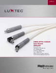
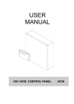
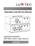
M L X 3 0 0 wat t x e n o n l i g h t s o u r c e
MLX 300 WATT
XENON LIGHT SOURCE
Operation and Service Manual
ENGLISH
99 Hartwell Street
West Boylston, MA 01583 USA
Tel: +1-508-835-9700
US Toll Free: 1-800-325-8966
Fax: +1-508-835-9976
Website: http://www.integra-surgical.com
E-mail: [email protected]
M L X 3 0 0 wat t x e n o n l i g h t s o u r c e
Table of Contents
Page
Description
2Indication For Use
3Symbols 4General Warnings 4
Precautions
5Overview
5-6Operation
6-7
Xenon Lamp Module Replacement 8
Fuse Replacement 9Optional Floor Stand Assembly
10Replacement Parts and Accessories
10
Maintenance and Cleaning
11Troubleshooting
12
Specifications
13-15Electromagnetic Compatibility (EMC)User Information
16
Block Diagram
17Repair and Return
17
Limited Warranty
1
M L X 3 0 0 wat t x e n o n l i g h t s o u r c e
indication for use
The Luxtec MLX light source is designed to supply high-intensity white light to a fiber optic cable for
illumination of a surgical field during a surgical and/or medical procedure.
2
M L X 3 0 0 wat t x e n o n l i g h t s o u r c e
SYMBOLS
TABLE OF SYMBOLS
Found on a medical grade light source, other illumination related equipment, fiber optic
cables and corresponding packaging.
Attention; Consult Accompanying Documents
Caution: High Voltage
Equipotentiality
Protective Earth
Fuse
Type CF Equipment
Type BF Equipment
High Temperature
On / Off
Brightness
Stand-by
Motor System Status Display
Fan
System
CE
Do Not Dispose
Listed by ETL
Push
Listed by CSA
Hours
Part Number
Over Temperature
Batch Code
Intensity Serial Number
or
Lamp
Keep dry
Authorized Representative in the
European Community
Manufacturer
3
M L X 3 0 0 wat t x e n o n l i g h t s o u r c e
GENERAL WARNINGS
• The user should carefully study the Operation
and Service Manual before using the equipment
in a clinical environment. Instructions should be
followed, with special attention given to warnings,
controls and user specifications. The Manual should
be available to the appropriate personnel.
•This Manual contains information about the proper
procedures for preparing this product for its use
and care.
• Before every procedure, carefully inspect the light
source to ensure it has been properly maintained
and cleaned, and that it is fully functional. DO NOT
use if inspection reveals any damage such as case
damage or loose connectors.
• Follow the instructions of other manufacturer’s
equipment when used in conjunction with this
product.
• To reduce the risk of fire and electric shock, do not
expose electrical equipment to moisture. When
cleaning, do not immerse any electrical device in
liquid.
•Do not use or store liquids on or above the light
source.
• SAFETY PRECAUTIONS MUST ALWAYS BE
EXERCISED WHEN USING ELECTRICAL
EQUIPMENT TO PREVENT OPERATOR/PATIENT
SHOCK, FIRE HAZARD OR EQUIPMENT
DAMAGE.
• Electric shock hazard. If unit is not functioning
properly, DO NOT OPEN. Please refer to the
Repair and Return Section of this Manual.
• All electrical equipment must be used with approved
hospital grade power cords and power plugs
inserted properly into grounded AC power outlets.
• The light source should never be used in ocular
surgery or in a surgical procedure requiring direct
illumination of the eye.
• Use care not to point any fiber optic cable directly
at the eye while operating the light source.
• The light source produces high intensity light.
Thermal burns can result from improper use of the
light source or from the light output of the fiber
optic cable.
4
• Explosion Hazard. Do not use in the presence of
flammable anesthetics, liquids, vapors, gases or dusts.
• Keep cooling vent and fans free of obstructions.
• FIRE HAZARD: DO NOT DRAPE OR COVER THE
LIGHT SOURCE WHILE IT IS OPERATING.
• When light source is not in use, turn off the power
or put the unit in stand-by mode.
• Ensure that the fiber optic cable matches the port
type to prevent damaging the optical components
of the light source. For user convenience, the light
source has a turret with labeled selectable ports.
• Do not use the headlight at distances of less than
10” (25cm).
precautions
• Take precautions to verify that the fiber optic cable
is appropriately suited for the light source. Xenon
and other high illumination light sources. require
premium fiber optic cables in order to achieve
optimal performance and prevent damage to the
fibers, thereby diminishing the quality of the light
output or the useful life of fiber optic cable.
• Take precautions not to touch or disconnect the
cable end fitting from the turret until the Light
Source has been “shut down” for a period of time
and allowed to cool. The cable end fitting will
remain hot immediately following shut down, which
can cause burns.
• Take precautions to not place and rest a hot cable
end fitting and/or head light on a patient or allow
the system to come in contact with un-protected
hands or tissue. The entire system should be
allowed to cool following use. Failure to do so can
cause burns and/or tissue damage.
M L X 3 0 0 wat t x e n o n l i g h t s o u r c e
OVERVIEW
The MLX light source delivers 300 spare watts of cool white infrared (IR) filtered light. The lamp is housed in a lamp
module that can be easily serviced without special tools.
Set Up and Inspection Before Use
The light source comes with the hospital grade power cord packaged separately. Verify that both components are in good
condition.
Before turning power on to the light source, make sure the unit is plugged into any standard 100VAC to 240VAC 4763Hz (as appropriate) outlet. Grounding reliability is guaranteed only when connected to a “hospital grade” receptacle.
Allow a minimum of 2 inches (5.08 cm) clearance at the rear and sides of the unit for cooling air flow. Ensure that the
unit is not near air exhaust or against other equipment.
WARNING: The MLX light source monitors air intake temperature and will turn off if ambient temperature is > 40O C
OPERATION
1. Insert a fiber optic cable in the proper port in the turret. The active port is indicated by a on
(See Figure 1). Available ports are ACMI, Olympus, Storz and Wolf cable-compatible. All ports
appropriately.
the front panel
are identified
2. Press the Power Switch in the upper left corner of the front panel (See Figure 2).
3. When the Power Switch is pressed the Stand-by Light (Figure 2) will blink and there will be a 3 – 4 second delay
before the Xenon Lamp illuminates while the system does a self-diagnostic check.
4. Press the Stand-by Button.
Power Switch
Active Point
Stand-by Button
Figure 1
Figure 2
5
M L X 3 0 0 wat t x e n o n l i g h t s o u r c e
OPERATION
5. The system will start up at the same light intensity as when last used (Figure 3). For new systems, the light
intensity will start at the minimum 20% setting.
6.To adjust the light intensity, push the Membrane Switches (Figure 3): + to increase or - to decrease the light
output or intensity. Range is 0%, 20 – 100% in 5% increments. Holding the + or – button will change the intensity
more quickly.
NOTE: It is strongly recommended that the light be used at the minimum intensity for good visualization.
7. The System Status Display can be pressed to show both lamp time and system operation time. A second press
of the switch will show the software version of the system monitor. A third press returns to light output. (The
system will automatically return to the light intensity reading after15 seconds).
8. The system can be placed in stand-by mode (no light emitted) allowing the surgeon to unplug a headlight and
move around the table, or to change cables in a laparoscopic or endoscopic procedure.
CAUTION: Cable end fitting can be HOT!!!
NOTE: If unit is left in stand-by mode for 15 minutes, it will automatically shut off the lamp. Fans will keep running.
To re-activate, push the Stand-by Button.
9. To shut the system off, simply press the main Power Switch as in Step 2.
Membrane
Switches
System
Status
Display
Figure 3
XENON LAMP MODULE REPLACEMENT
Note: Please adhere to appropriate safety precautions when performing lamp replacement. Only qualified
personnel should service this device. Protective facemask and/or proper safety glasses should be
worn when replacing the lamp module. Before changing the lamp module, turn power off and allow
the light source to cool for at least fifteen (15) minutes.
Please read and comply with all Precautions and General Warnings listed in this manual.
6
M L X 3 0 0 wat t x e n o n l i g h t s o u r c e
XENON LAMP MODULE REPLACEMENT
To remove:
1. Make sure the power is off and the hospital grade power cord is disconnected.
2. Remove the retaining screws from the top plate (Figure 4) and retain screws.
3. Slide the top plate towards the back of the unit until it stops.
4. Lift the top cover up and off the unit.
5. Unscrew the lamp module door and remove (Figure 5) and retain screw.
6. Grasp the module by the tabs and pull directly up (Figure 6).
Figure 4
RESET
Figure 6
Figure 5
Figure 7
To Replace:
1. Orient the lamp module (P/N 001320LX) to face forward.
2. Place the module into the light source.
3. Seat module securely.
4. Replace the lamp module door and secure it with the screw.
5. Align top cover brackets into slots and slide forward.
6. Slide the top plate forward until it engages the front panel.
7. Replace the retaining screws in the rear panel.
8. Replace the hospital grade power cord and turn on power to verify operation.
To Reset Lamp Age Meter:
1. Using the membrane switch, turn the display to the lamp age/system age screen.
2. On the rear of the unit insert a pen/pencil or other suitable pointed object into the slot marked RESET (Figure 7).
3. Push until a click is felt.
4.Verify that the lamp age has been reset to 0.
NOTE: The System Age reading CANNOT be reset.
7
M L X 3 0 0 wat t x e n o n l i g h t s o u r c e
FUSE REPLACEMENT
To replace the fuse:
• The fuse for the light source is located in the power entry module in
the rear of the unit.
• Remove the hospital grade power cord from the back of the light
source.
• Using a small flat screwdriver, pry open the retaining
door (Figure 8)and pry out the red plastic block from the power
entry module (Figure 9).
• Check to see if the fuse is blown; if blown replace with a fuse of the
same rating (Luxtec P/N 600987, or T6.3AL250 ).
• Replace the red block in the housing.
• Snap the retaining door into place.
• Plug cord back into light source and retest the unit.
Figure 8
Figure 9
8
M L X 3 0 0 wat t x e n o n l i g h t s o u r c e
OPTIONAL FLOOR STAND ASSEMBLY
There are four (4) parts to the floor stand assembly:
(Figure 10).
(Phillips head screwdriver included for assembly)
1. Base with five (5) casters (2 locking)
2. One column with light source base plate
3. Handle
4. MLX light source base
Floor stand assembly instructions:
1. With the handle positioned so that the Luxtec® logo is
properly aligned, slide the handle onto the column and
center the handle about 5 inches (13cm) below the light
source base plate. Tighten handle screw to hold in place.
2. Insert assembled column into the base. Seat firmly.
3. Attach the light source base onto the base plate
(Figure 10) with the four (4) screws provided, using the Phillips
head screwdriver provided.
Figure 10
4. Secure the light source to base plate by aligning
the feet to the holes on the surface of the plate. Tighten
the two screws on the bottom of the plate to the light source (Figure 11).
Figure 11
9
M L X 3 0 0 wat t x e n o n l i g h t s o u r c e
REPLACEMENT PARTS AND ACCESSORIES
To place an order, contact your local Luxtec distributor or call Luxtec Customer Service at 1-800-325-8966
(USA & Canada only) or +1-508-835-9700 to identify your local Luxtec representative.
Light Source
00MLX
300 Watt Xenon Light Source with Turret (ACMI, Wolf, Storz and Olympus)
Accessories
001320LX Xenon Lamp Module
600987
Fuse 6.3 Amp, Slow Blow
850469Operating and Service Manual MLX light source
Optional Accessories
AX2100BIFUltraLite® Pro headlight with 9ft (275cm) premium bifurcated cable.
Mark II module and gown clips.
AX2100BIFSLUltraLite® Pro headlight with 9ft (275cm) premium bifurcated cable,
Mark II module and gown clips with short linkage.
001337
MLX Floorstand
MAINTENANCE AND CLEANING
• Allow unit to cool for at least 15 minutes prior to cleaning.
Unplug the power cord before cleaning. The light source exterior can be cleaned and disinfected using 70%
isopropyl alcohol. Allow 5 minutes for alcohol to evaporate before reconnecting to power.
Use a vacuum cleaner and a soft brush to remove visible dust accumulation from fan and vent holes whenever
necessary and always when replacing the lamp.
10
M L X 3 0 0 wat t x e n o n l i g h t s o u r c e
TROUBLESHOOTING
11
M L X 3 0 0 wat t x e n o n l i g h t s o u r c e
SPECIFICATIONS
12
M L X 3 0 0 wat t x e n o n l i g h t s o u r c e
Electromagnetic Compatibility (EMC) User Information
WARNING: Medical Electrical Equipment needs special precautions regarding EMC and needs to be installed and
put into service according to the Electromagnetic Compatibility [EMC] information provided in the accompanying
documents.
WARNING: Portable and Mobile RF Communications Equipment can affect Medical Electrical Equipment.
WARNING: The equipment or system should not be used adjacent to or stacked with other equipment and that if
adjacent or stacked use is necessary, the equipment or system should be observed to verify normal operation in the
configuration in which it will be used.
NOTE: The EMC tables and other guidelines that are included in the Instruction Manual provide information to the
customer or user that is essential in determining the suitability of the Equipment or System for the Electromagnetic
Environment of use, and in managing the Electromagnetic Environment of use to permit the Equipment or System to
perform its intended use without disturbing other Equipment and Systems or non-medical electrical equipment.
Table 201
Guidance and Manufacturer’s Declaration – Emissions All Equipment and Systems
The MLX light source is intended for use in the electromagnetic environment specified below.
The customer or user of the MLX light source should assure that it is used in such an environment.
Emissions Test
RF Emissions
CISPR 11
Compliance
Group 1
Electromagnetic Enforcement – guidance
The MLX unit uses RF energy only for its internal function. Therefore, its RF
emissions are very low and are not likely to cause any interference in nearby
electronic equipment.
Class B
RF Emissions
CISPR 11
Radiated and
Conducted
Emissions
The MLX unit is suitable for use in all establishments including domestic, and
those directly connected to the public low-voltage power supply network that
supplies buildings used for domestic purposes.
Conducted Emissions Tests Performed at both 240VAC, 50Hz and 120VAC,
60Hz
Harmonics
IEC 61000-3-2
Flicker
IEC 61000-3-3
N/A
Equipment intended for Professional Use Only
N/A
Equipment intended for Professional Use Only
13
M L X 3 0 0 wat t x e n o n l i g h t s o u r c e
Electromagnetic Compatibility (EMC) User Information
Table 202
Guidance and Manufacturer’s Declaration—Immunity All Equipment and Systems
The MLX light source is intended for use in the electromagnetic environment specified below. The customer or user of
the MLX light source should assure that it is used in such an environment.
Immunity Test
IEC 60601 Test Level
Compliance Level
Electrostatic
Discharge (ESD)
IEC 61000-4-2
±6kV contact
±6kV contact
±8kV air
±8kV air
Electrical Fast
Transient/burst
IEC 61000-4-4
±2kV on AC Mains
±2kV on AC Mains
Surge
IEC 61000-4-5
±1kV Differential
±2kV Common
Electromagnetic Environment - Guidance
Floors should be wood, concrete or ceramic tile. If
floors are synthetic, the relative humidity should be
at least 30%.
Mains power quality should be that of a typical
commercial or hospital environment.
Note - Tests Performed at both 240VAC, 50Hz and
120VAC, 60Hz
±1kV Differential
±2kV Common
Mains power quality should be that of a typical
commercial or hospital environment.
Note - Tests Performed at both 240VAC, 50Hz and
120VAC, 60Hz
Voltage dips,
short interruptions and voltage
variations on
power supply
input lines
IEC 61000-4-11
Power Frequency
50/60Hz
Magnetic Field
IEC 61000-4-8
14
>95% Dip for
0.5 Cycle
>95% Dip for
0.5 Cycle
60% Dip for
5 Cycles
60% Dip for
5 Cycles
30% Dip for
25 Cycles
30% Dip for
25 Cycles
>95% Dip for
5 Seconds
>95% Dip for
5 Seconds
3A/m
3A/m
Mains power quality should be that of a typical
commercial or hospital environment. If the user of
the MLX unit requires continued operation during
power mains interruptions, it is recommended that
the MLX unit be powered from an uninterruptible
power supply or battery.
Note - Tests Performed at both 240VAC, 50Hz and
120VAC, 60Hz
Power frequency magnetic fields should be that of a
typical location in a typical commercial or hospital
environment.
Note - Tests Performed at both 50Hz and 60Hz
M L X 3 0 0 wat t x e n o n l i g h t s o u r c e
Electromagnetic Compatibility (EMC) User Information
Table 204
Guidance and Manufacturer’s Declaration – Emissions Equipment and Systems that are NOT Life-Supporting
The MLX light source is intended for use in the electromagnetic environment specified below. The customer or user
of the MLX light source unit should ensure that it is used in such an environment.
Immunity Test
IEC 60601
Test Level
Compliance
Level
Conducted RF
3 Vrms from
V1 = 3 Vrms
IEC 61000-4-6
150 kHz to
80 MHz
Radiated RF
3 V/m
IEC 61000-4-3
80 MHz to
2.5 GHz
Electromagnetic Environment – Guidance
Portable and mobile RF communications equipment should
be separated from the MLX light source by no less than the
recommended separation distances calculated/listed below:
D = (3.5 / V 1) P
E1 = 3V/m
D = (3.5 / E1) P
D = (7 / E1) P
80 to 800 MHz
800 MHz to 2.5 GHz
Where P is the maximum power rating in watts and D is the
recommended separation distance in meters.
Field strengths from fixed transmitters, as determined by an
electromagnetic site survey, should be less that the compliance
levels (V1 and E1).
Interference may occur in the vicinity of equipment containing a
transmitter.
Table 206
Recommended Separation Distances Between Portable and Mobile RF Communications
Equipment and the MLX Equipment and Systems that are NOT Life-Supporting
The MLX light source is intended for use in the electromagnetic environment in which radiated disturbances
are controlled. The customer or user of the MLX light source can help prevent electromagnetic interference by
maintaining a minimum distance between portable and mobile RF Communications Equipment and the MLX
light source as recommended below, according to the maximum output power of the communications
equipment.
Recommended Separation Distances for the MLX (meters)
150 kHz to 80
MHz
80 to 800MHz
800 MHz to 2.5 GHz
(Watts)
d = 1.1667 P
d = 1.1667 P
d = 2.3333 P
0.01
0.11667
0.11667
0.23333
0.1
0.36894
0.36894
0.73785
1
1.1667
1.1667
2.3333
10
3.6894
3.6894
7.3785
100
11.667
11.667
23.333
Maximum
Output Power
15
M L X 3 0 0 wat t x e n o n l i g h t s o u r c e
BLOCK DIAGRAM
16
M L X 3 0 0 wat t x e n o n l i g h t s o u r c e
REPAIR AND RETURN INFORMATION
This device must be clean and decontaminated prior to return to Luxtec. Luxtec reserves the right to return
unrepaired any equipment that is contaminated with blood or other organic material.
Warranty Service and Repair:
To obtain service under warranty or return product for repair, the customer should contact your local Luxtec
representative or call Luxtec Customer Service at 1-800-325-8966 or +1-508-835-9700.
LIMITED EXPRESS WARRANTY
Luxtec warrants that the new MLX light source shall be free from defects in material and workmanship under normal use and
service for a period of three (3) years from the date of shipment. Luxtec’s sole and exclusive liability under the warranty shall
be, at Luxtec’s option, either to repair any component which fails during the warranty period due to any defect in workmanship
or material F.O.B. factory if:
1. Customer promptly reports such defect to Luxtec in writing,
2. If requested by Luxtec, customer returns equipment to Luxtec with shipping charges and,
3. Upon inspection, Luxtec finds the equipment to be defective.
This warranty is contingent upon normal and proper use of the equipment. It does not cover equipment that has been modified
with non-Luxtec parts without the written approval of Luxtec, subjected to unusual physical or electrical stress, or damaged
during shipment. This warranty is non-transferable unless authorized in writing by Luxtec.
Luxtec reserves the right to make design changes on its products without liability to incorporate said change in Luxtec products
previously designed or sold.
Upon receipt of the product, it should be carefully inspected. If any defect is discovered, notification must be given immediately
to the manufacturer or authorized distributor.
17
M L X 3 0 0 wat t x e n o n l i g h t s o u r c e
Three-point Comfort System
www.Integra-Surgical.com
The Integra wave logo and Integra Surgical are trademarks of Integra LifeSciences Corporation.
Luxtec and UltraLite are registered trademark of Integra LifeSciences Corporation or its subsidiaries.
Copyright © 2010 Integra LifeSciences Corporation. All rights reserved.
Printed in USA Xk
P/N 850469 Rev. B
01/10