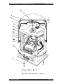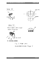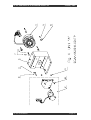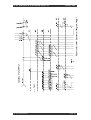
1
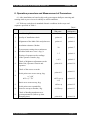
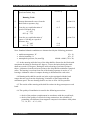
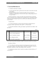
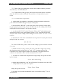
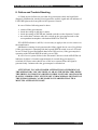
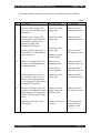
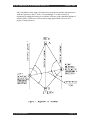
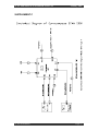
SERVICE & REPAIR MANUAL SCAN 2000 GYROCOMPASS SCAN 2000 SERVICE & REPAIR MANUAL January 2001 CONTENTS SERVICE MANUAL SCAN. 461524.001 NB ...................................................................... 3 1. INTRODUCTION .................................................................................................................................. 4 2. GENERAL REQUIREMENTS .................................................................................................................. 5 3. SAFETY PRECAUTIONS ........................................................................................................................ 7 4. INSTALLATION AND WIRING ................................................................................................................ 8 5. PREPARATION FOR USE ....................................................................................................................... 10 6. OPERATION PROCEDURE AND MEASUREMENT OF PARAMETERS ......................................................... 11 7. TECHNICAL MAINTENANCE ................................................................................................................ 17 8. FAILURE AND TROUBLE-SHOOTING .................................................................................................... 21 9. STORAGE AND SHIPMENT INSTRUCTIONS ............................................................................................ 23 SUPPLEMENT A.................................................................................................................................. 24 SUPPLEMENT B .................................................................................................................................. 26 SUPPLEMENT C .................................................................................................................................. 27 REPAIR MANUAL SCAN. 461841.001 TP .......................................................................... 31 1. INSTRUCTION CARD NO 1 ........................................................................................................... 32 1.1General Requirements .................................................................................................................. 32 1.2 Basic Requirement and Arrangement of Gyrocompass “SCAN 2000” Repair ........................... 33 2. INSTRUCTION CARD NO 2 ........................................................................................................... 34 2.1 Indicator Replacement ................................................................................................................. 34 3. INSTRUCTION CARD NO 3 ........................................................................................................... 35 3.1 Supply Unit Replacement ............................................................................................................ 35 3.2 Replacement of Printed Circuit Boards ....................................................................................... 35 4. INSTRUCTION CARD NO 4 ........................................................................................................... 36 4.1 General Instructions .................................................................................................................... 36 4.2 Main Unit Disassembly ............................................................................................................... 36 4.3 Instrument Light Replacemant .................................................................................................... 37 4.4 Final Assembly of Main Unit ...................................................................................................... 38 4.5 Accelerometer Replacement ........................................................................................................ 38 4.6 Gyroscope Replacement............................................................................................................... 40 4.7 Check and Adjustment of Gyrocompass “SCAN 2000” After Accelerometer and Gyroscope Replacement ...................................................................................................................................... 41 4.8 Testing of Gyrocompass “SCAN 2000” After Accelerometer and Gyroscope Replacement....... 42 DRAWING, SCAN.468332003 Operator Console ............................................................................... 43 DRAWING, SCAN.468353001, Electronic Unit .................................................................................. 44 DRAWING, SCAN.462.515.001, Main Unit ....................................................................................... 45 DRAWING, Unit "A" ........................................................................................................................... 47 WIRING DIAGRAM, Electronic Unit .................................................................................................. 48 SCAN-STEERING Page 2 SCAN 2000 SERVICE & REPAIR MANUAL January 2001 Service Manual SCAN.461524.001 NB SCAN-STEERING Page 3 SCAN 2000 SERVICE & REPAIR MANUAL January 2001 1. Introduction This Service Manual SCAN.461524.001 NB is intended for gyrocompass SCAN 2000 operational personnel. It includes all necessary data for proper usage, technical support, transportation and storage of gyrocompass as well a maintenance of its operational status. SCAN-STEERING Page 4 SCAN 2000 SERVICE & REPAIR MANUAL January 2001 2. General Requirements 2.1 Reliable operation of gyrocompass “SCAN 2000” is achieved by daily monitoring and observance of requirements given in this Manual. 2.2 Gyrocompass “SCAN 2000” is designed for navigation in latitudes up to 75 degrees at speed up to 90 knots under the following conditions: • temperature range from -10°C to +55°C (from -40°C to +65°C for bearing repeaters, peloruses and direction finders); • sinusoidal vibration in the frequency range from 5 to 80 Hz with amplitude ±1.6 mm for frequencies from 5 to 13.2 Hz and with acceleration 10 m/sq.s for frequencies from 13.2 to 80 Hz; • rolling motion with amplitude (20±2) and period from 6 to 15 s; • pitching motion with amplitude (10±1) and period from 6 to 15 s; • yawing with amplitude (5±1) and period from 6 to 15 s, • voltage and frequency variations (220±22)V, (50±3)Hz in vessel’s AC electrical system and voltage variation • from 19.2v to 31.2V in DC electrical system; • maximum tilt of 45 degrees. Under these conditions gyrocompass provides: determination of heading against geographical meridian; • transmission of heading data to analog and digital receivers, • automatic receipt of speed and latitude inputs from GPS; • automatic receipt of speed input from log, • manual input of speed and latitude; • remote control from the Operator Console; • connection with electric radionavigational equipment including radio direction-finder, radar, autopilot, integrated navigation system etc. 2.3 Gyrocompass preserves its performance being exposed to the following conditions: • minimum temperature -60°C, • ceiling temperature +70°C • excessive humidity 95% at temperature +40°C • mechanical impact with maximum acceleration 100 m/sq.s and pulse duration 10-15 ms. 2.4 Gyrocompass has the following power supply circuits: • 24V DC for the basic modification • 220Vm 50 Hz and 24V DC (battery) when modified with power supply 2ps 220” 2.5 Installation and wiring of the gyrocompass is carried out after all construction and finishing works in navigation spaces of the ship are done. SCAN-STEERING Page 5 SCAN 2000 SERVICE & REPAIR MANUAL January 2001 2.6 Before introduction into service the gyrocompass should pass mooring and running trials according to the procedure and in terms specified in Section 6. 2.7 Gyrocompass operation conditions shall meet requirements for static electricity. Allowable value of electrostatic potential is 100 V. SCAN-STEERING Page 6 SCAN 2000 SERVICE & REPAIR MANUAL January 2001 3. Safety Precautions 3.1 Only trained personnel familiar with the design and working principle of the gyrocompass “SCAN 2000” (Specification SCAN.461524.001 TO) is permitted to operate this instrument. 3.2 When working on the gyrocompass it is necessary to observe the safety regulations on service of electrical devices as well as standing safety engineering and fire safety rules. 3.3 Devices that constitute the gyrocompass “SCAN 2000” shall be grounded to the hull in the shortest possible way. Successive grounding is not allowed. 3.4 Shielding of interconnect cables shall be electrically connected with the hull. 3.5 When the gyrocompass is operating, all it’s covers must be locked. 3.6 Installation, wiring and replacement of the gyrocompass units are carried out only when the gyrocompass I de-energized. 3.7 Rating of fuses shall correspond to that indicated on the devices. Replacement of fuses is made only when the gyrocompass is switched off. SCAN-STEERING Page 7 SCAN 2000 SERVICE & REPAIR MANUAL January 2001 4. Installation and Wiring 4.1 Before the installation and wiring of the gyrocompass on the ship one should carefully study Specification SCAN.461524.001 TO as well as Specification for all periphery equipment. 4.2 Installation of Gyrocompass units. 4.2.1 Distance between the Main Unit and the Electronic Unit shall not exceed 2 meters. They must be placed in a room where there are no sudden temperature fluctuations and humidity and vibration are within the limits specified in Section 2. The Main Unit must be mounted on a rigid metal foundation that is secured to the deck close to the ship’s center of mass. Notches on the base of the Main Unit shall be parallel to the longitudinal central plane of the ship. Accuracy of alignment shall be ±0.2 degree. Cable connectors of the Main Unit shall face the bow of the ship. Free access to the Main Unit shall be provided from the side where connectors are located and from the top - not less than 0.5 meter, from all other sides - 0.2 meters. 4.2.2 It is recommended to place the Operator Console close to the working area of a navigator to ensure convenient manipulation of its switches and buttons. The Operator Console can be secured on some vertical or horizontal plane due to it’s rotating bracket. Length of the cable that interconnect the Operator Console and the Electronic Unit shall not exceed 50 meters. 4.2.3 It is recommended to install the Distribution Box in same room with Main Unit and the Electronic Unit. Length of the cable connecting the Distribution Box to the Electronic Unit shall not exceed 50 meters. 4.2.4 The bearing repeater shall be mounted onto a pelorus. Axes of the repeater are placed into nylon sleeves that are inserted into slots of the gimbal ring of a pelorus. The place of installation of analog and digital steering repeater shall guarantee the ease of the heading reading. Length of cable connecting any repeater (DE 180, DE 200, BRA 250, BRB 250, BRC 250) to the Electronic unit or Distributor Box shall not exceed 200 meters. 4.2.5 Peloruses shall be installed in places that ensure maximum field of view for the direction finding. Line 0° - 180° of the bearing repeater azimuth scale shall be parallel to the longitudinal central plane of the ship with maximum error ±0.2 degree. Reading 0° of the scale shall be direct to the stern and 180° to the bow of the vessel. SCAN-STEERING Page 8 SCAN 2000 SERVICE & REPAIR MANUAL January 2001 4.2.6 Location of the course recorder shall provide the ease of data reading and servicing. 4.2.7 It is desirable to place Supply Unit PS 220 in the same room with Electronic Unit. Length of cables connecting the Supply Unit with Electronic Unit and vessel’s mains shall not exceed 25 meters. 4.2.98 The minimum distance between the units of the gyrocompass and the magnetic compass shall be 0.5 meter with the following exceptions: Peloruses and course recorder - minimum 1.5 m Bearing Repeaters - minimum 1 m. 4.3 Wiring of Gyrocompass Units 4.3.1 Wiring of the gyrocompass “SCAN 2000” is performed in accordance with: 4.3.2 • Wiring Diagram SCAN.461524.001 B6 for the basic set • Wiring DiagramSCAN.461524.001-01 B6 for basic set with PS 220 power supply They are given in the Supplement c to this Manual 4.3.2 Two independent feeders can be provided to energize the gyrocompass. Modifications SCAN.461524.001 from main 24V DC supply, and SCAN.461524.001-01 from the main switchboard and emergency supply unit (battery). 4.3.3 The automatic switching from the main to the emergency feeder is made with the help of the Supply Unit PS 220. 4.3.4 Each unit of the gyrocompass is delivered with the set of mounting and spare parts in accordance with the factory certificate. SCAN-STEERING Page 9 SCAN 2000 SERVICE & REPAIR MANUAL January 2001 5. Preparation for use Before switching on the gyrocompass the following operations shall be done: 5.1 Operator Console • set SPEED switch to “0” position • set LATITUDE switch to “0” position • set the dimmer in medium position 5.2 Electronic Unit • open the cover and set “NORMAL” selector to “TEST” position 5.3 Main Unit • set the dimmer into medium position 5.4 Repeaters • set the dimmer into medium position 5.5 Course Recorder • all preparatory works are done in accordance with the Instructions Manual for the course recorder. SCAN-STEERING Page 10 SCAN 2000 SERVICE & REPAIR MANUAL January 2001 6. Operation procedure and Measurement of Parameters 6.1 After installation on board a ship each gyrocompass shall pass mooring and running trials to prove its serviceability in actual conditions. 6.2 Trials are carried out in standard climatic conditions in the scope and sequence specified in Table 1. No. Parameter Requirement or SM point Table 1 Method (SM point) Mooring Trials 1. Quality of installation check. point 6.6 point 6.6 2. Alignment of the Main Unit and peloruses point 6.6 point 6.6 20 point 6.7 1.5 point 6.8 ± 0.2 point 6.9 point 6.10 point 6.10 point 6.11 point 6.11 ±0.35 sec. ϕ ±1.5 point 6.12 ±0.2sec ϕ point 6.12 insulation resistance, Mohm 3. 4. Gyrocompass setting time at unknown meridian with max. error 1 deg., h 5. Slaving of repeaters tot he readings of the operator Console, deg. 6. Check of brightness adjustment on the Main Unit, Operator Console and repeaters. Check of the course recorder. 7. 8. Settle point error at one run-up, deg. ϕ ≤ 60° 60° < ϕ ≤ 75° Static error at one run-up, deg. 9. 10. Settle point error repeatability from one run-up to another, deg. ±0.25sec ϕ point 6.13 11. Check of heading translator servo system parameters (follow-up time. Damping time). point 6.14 point 6.14 SCAN-STEERING Page 11 SCAN 2000 SERVICE & REPAIR MANUAL 12. Speed compensation error (with 20 knots speed correction), deg. January 2001 ±0.2 sec ϕ point 6.15 Running Trials 13. Remote data transfer error, from the Main Unit to repeaters, deg. ±0.2 point 6.16 14 Error due to a rapid alteration of speed of 20 knots, deg. ϕ ≤ 60° 60° < ϕ ≤ 75° ±1.5 point 6.16 .15. Error due to a rapid alteration of course of 180 deg at a speed of 20 knots, deg. ϕ ≤ 60° 60° < ϕ ≤ 75° ±2 point 5.16 ±2.0 ±2.5 Note: Standard climatic conditions are characterized by the following parameter • ambient temperature, °C • relative humidity, % • atmospheric pressure, Pa (mm Hg) 25 ± 10 65 ± 15 100000 ± 4000 (750 ± 30) 6.3 At the mooring trials the bow of the ship shall be directed to the North with maximum deviation in direction ±45 degrees. Course deviation during the trials shall not exceed 0.25 degrees. During the trials a bearing of reference points is taken. A distance from the reference points to the ship shall be minimum 2 nautical miles. The bearing is read out from one of the bearing repeaters in series of 3-5 bearings. Arithmetic value of compass bearing is determined for each series. 6.4 Running trials shall be carried out in the region equipped with the head ranges that are seen from the ship during 30 minutes of movement with the maximum speed. The true bearing shall be as close to 0° or 180° as possible. 6.5 The results of the mooring trials shall be written in the gyrocompass record book. 6.6 The quality of installation is tested in the following succession: • check of the product completement in accordance with the record book; • check of the quality of electrical wiring connections, the reliability of grounding, safe distance from magnetic compass in accordance with points 3.3, 3.4, 4.3.1 - 4.3.3, 4.2.9; SCAN-STEERING Page 12 SCAN 2000 SERVICE & REPAIR MANUAL January 2001 • check of the Main Unit installation in accordance with point 4.2.1; • check of peloruses installation in accordance with point 4.2.5. In case there is no marking of the line parallel to longitudional center plane of ship, pelorusses alignment shall be made in accordance with the Supplement A. 6.7 Insulation resistance check is made as follows: • All modifications. Measure insulation resistance between the Electronic Unit and connector’s pins X12:3, X12:4, X19:4, with the help of a teraohmmeter with voltage range 100V. • Modification SCAN.461524.001-01. In addition to the above mentioned, measure insulation resistance between the casing of the Supply Unit PS 220 and connector’s pin X1:1 with power switched on. Use a teraohmmeter with voltage range 500V. In all cases insulation resistance shall not be less than 20 Mohm. Testing of the gyrocompass settling time is performed in the following session: 1. When the gyrocompass is prepared for use in accordance with Section 5 of this Manual, energize the Electronic Unit with supply voltage 24V DC: • Modification SCAN.461514.001. Switch on external supply of 24V DC. • Modification SCAN.461524.001-01. Switch on external supply of 220V AC, 50 Hz and 24V DC. 2. Set the local latitude by the LATITUDE switch on the Operator Console: the upper switch is for tens in the range from 0 to 180 degrees, the lower is for units in range from 0 to 9 degrees. 3. Switch on the gyrocompass with the button START on the Operator Console. The START button lights, 4.Use buttons NORTH or SOUTH on the Operator Console to set the correspondent hemisphere. After pressing the button lights. Write down the time when the gyrocompass was switched on in the record book. The operator Console digital display will indicate the azimuth position of gyro unit against ship’s central plane on the moment of the gyrocompass switching on. The gyrocompass is automatically aligned. Alignment time is within 25 to 120 minutes and depends on the gyro unit initial angle of deflection from the meridian and run-up conditions (temperature, inclination angle, local latitude). The gyro is considered to be aligned when the green LED “READY” on the front panel of the Operator Console lights. Settle point error shall not exceed 1 degree. Fine alignment of gyrocompass with the settle point error 0.35 degree per secant latitude can be achieved within maximum 2 hours after illumination of READY indicator dependent on sailing conditions. SCAN-STEERING Page 13 SCAN 2000 SERVICE & REPAIR MANUAL January 2001 6.9 The check of adjustable lights for illumination of gyrocompass and repeaters readings is carried out after testing under the point 6.8. Turning the dimmers on the Operators Console, DE180, DE200, BRA250, BRB250, BRC250, check the existence of light and adjustability of brightness. 6.10 The course recorder is checked in accordance with the specification for the given recorder 6.11 The check of the settle point error and static error in one run-up is made as follows: 1. When the gyrocompass is ready for operation but not earlier than 2 hours after switch on, take 10 readings at 20 minutes intervals of compass bearing (CB) of a remote reference point the true bearing (TB) of which is known with the error ±0.2 degree maximum. 2. Use these 10 readings to calculate the settled value of the compass bearing by formula: CBset = 1 10 ∗ ∑ CBi 10 i =1 where CBi - ten readings taken at 20 minutes intervals. 3. Calculate the settle point error (SPE) as the difference between the settled compass bearing (Cbset) and true bearing (TB) of the reference point. SPE value shall not exceed the one given in the Table 1. If SPE value is beyond tolerance limits, check the correctness of installation of the main unit and peloruses under the point 6.6 4. Calculate the difference between the Cbset and each of ten readings CBI by the formula: DCBi = Cbi - Cbset 5. Calculate the static error (Est) as RMS value of differences between ten individual values of compass bearing (CB) and CBset by the following formula: Est = 1 10 ∗ ∑ (∆CBi )2 9 i =1 Error shall not exceed the value specified in Table 1. SCAN-STEERING Page 14 SCAN 2000 SERVICE & REPAIR MANUAL January 2001 6.12 Settle point error repeatability from one run-up to another is tested after the above (p.6.11) test is finished and the settle point error SPE in the first run-up is determined. The procedure of testing is as follows: 1. Switch off the gyrocompass pressing STOP button on the front panel of the Operator Console and de-energize: • Modification SCAN.461524.001 external 24V DC power supply • Modification SCAN.461514.001-01 external 220V AC and 24V DC power supply. 2. After at least 12 hours but not later than 7 days the gyrocompass is started again and the determination of the settle value of the compass bearing Cbset and settle point error SPE is repeated in accordance with the procedure specified in pp. 6.8 - 6.11 81-3) The difference between SPE in the first and the second run-up is considered to be the indication of the settle point heading instability. This value, including the Main Unit and peloruses alignment error, shall not exceed the value given in Table 1. 6.13 Speed compensation error is checked after the gyrocompass is tested under p. 6.12. • Set the SPEED switch on the front panel of the Operator Console to 20 knots. • Three hours later take a bearing and define the new value of the settled compass bearing CBset’ in accordance with pp- 6.12.1, 6.12.11. • Calculate speed compensation error by the formula: Esp = CBset’ - CBset - Cbcom where CBset’ is the settled value of compass bearing in the second run-up determined in accordance with p. 6.12; Cbcom is theoretically computed value of the settle point heading for the latitude of the test by the formula: CBcom = 1.27•cosK•sec lat. Where K is the course at which the ship is moored and lat. Is the local latitude. Speed compensation error ESP including alignment error of the Main Unit and peloruses shall not exceed the value specified in Table 1. SCAN-STEERING Page 15 SCAN 2000 SERVICE & REPAIR MANUAL January 2001 6.14 The following procedure is recommended for the running trials: When the mooring trials are finished, she ship goes to the region of the running trials and heaves aback or comes to an anchor for the time period of 2 hours minimum. After that the ship at a dead slow speed is brought on the ranges. Moving along the ranges she rapidly increase her speed up to 20 knots. Follow up the increase of speed manually turning the SPEED switch on the Operator Console. If the log is connected to the gyrocompass, set the upper switch SPEED on the Operator Console to LOG. If GPS-receiver is connected to the gyrocompass, set the upper switch SPEED to GPS position. In the last two cases green indicator LOG/GPS lights on the Operator Console. When the ship approaches the range as close as possible at speed 20 knots, she turns to 180 degrees and proceeds in reverse direction along the ranges until they are seen. The actual scheme of the ship’s running is adapted to the circumstances of navigation. When the ship is within the ranges and her speed rapidly changes to 20 knots and her course to 180 degrees, compass bearings of the range (true bearing of which is known with an accuracy ±0.2 degree) is taken from one of the peloruses with intervals of 5 - 10 minutes. Interval duration depends upon the scheme of ship’s running. For each compass bearing Cbi the error is calculated by the formula. <Hj = TB - CBj - SPE Values Hì received during the running trials shall not exceed those specified in the Table 1. 6.14.6 During the running trials it is necessary to compare the heading indicated on the Operator Console display and the readings of repeaters. Difference shall not exceed ±0.2 degrees. 6.15 To test the operational status of all navigation equipment installed on the ship mooring and running trials shall be performed annually. SCAN-STEERING Page 16 SCAN 2000 SERVICE & REPAIR MANUAL January 2001 7. Technical Maintenance 7.1 Technical maintenance includes: • on-line maintenance that is performed at each switch on and switch off of the gyrocompass; • periodic maintenance that is performed annually if the gyrocompass is installed on a sailing ship as well as after the repair or long storage period of the gyrocompass. Technical maintenance of the gyrocompass and trouble shooting on board the ship are performed by the specialist who is responsible for its serviceability. Repair of the gyrocompass and post-repair test are made by the authorized personnel of service centers. 7.2 Main checks 7.2.1 On-line maintenance consists of the gyrocompass condition check in accordance with the requirements of the point 7.3.1 of this manual. 7.2.2 Periodic maintenance of the gyrocompass is performed in accordance with the Table 2. Check 1. Check of external appearance 2. Check of insulation resistance 3. Gyro settling time check 4. Gyro bias drift compensation Value Table 2 Regularity monthly min. 20 MOhm once a year min. 1.5 h at each run-up max. ±0.2 deg once a year The result of the periodic maintenance shall be written down into the record book. Procedure of checks 7.3.1 It is allowed to make gyrocompass external appearance inspection with gyrocompass running. Gyrocompass units are checked for cleanliness, security of attachment, condition of cables and reliability of their connection. 7.3.2 Insulation resistance check is made in accordance with described in p. 6.7 of this Manual. SCAN-STEERING Page 17 SCAN 2000 SERVICE & REPAIR MANUAL January 2001 7.3.3 Check of the gyro settling time is made in accordance with the procedure described in p. 6.8 of this Manual. 7.3.4 Compensation of the gyro bias drift is made in normal climatic conditions when the ship is moored to the berth. The procedure of compensation is given below. 7.3.4.1 Azimuth drift compensation: a) switch on the gyrocompass in accordance with the procedure described in p.6.8 of this M and define the gyrocompass settling time; b) when indicator “READY” on the front panel of the Operator Console lights, let gyrocompass operate during 2 hours and after that take the reading of the current heading Ho from the display of the Operator Console; c) set the switch “CG-GA” on the Electronic Unit to “GA” and simultaneously start the stop watch. Let the gyrocompass operate in “GA” mode for an hour and after that make another reading of the heading H1. Set the switch “GC-GA” to “GC” position; d) determine the value of the azimuth drift for the period of 1 hour by the formula taking the sign into account: H = H1 - Ho The value of DH will be positive if the second reading is greater than the first and vice versa. e) if DH exceeds ±0.2 deg., measure the value of the DC voltage UNA (taking the sign into account) on the jacks “NA” and “O.T.” (common point) of the Electronic Unit. Use the digital voltmeter for measuring. The signal lead of the voltmeter is connected to “NA” and the common lead - to “O.T.” f) calculate the azimuth drift compensation voltage taking the sign into account by the formula: Ucom = H • 400 mV/deg g) turning the potentiometer “NA” on the Electronic Unit set the new value of DC voltage UýwA on the jack “NA” equal to: U’NA = UNA + Ucom taking the sign into account h) calculate once again the azimuth drift value in accordance with p.7.3.4 c,d. The difference SCAN-STEERING Page 18 SCAN 2000 SERVICE & REPAIR MANUAL January 2001 H = H1 - Ho shall not exceed 0.2 degree, otherwise compensation must be repeated. Example: Ho = 0.4°; h1 = 359.6°, UNA = 100 mV H = H1 - Ho = 359.6° - 0.4° = 0.8° Ucom = H • 400 Mv/deg = -0.8° • 400 mV/deg = - 320 mV The new value of DC voltage U’NA on the jack “NA” that was set by potentiometer turning is U’NA = UNA + Ucom = 100 mV + (-320 mV) = - 220 mV 7.3.4.2 Horizontal drift compensation: a) after testing on p.7.3.4 and two hour operation of gyrocompass in “CG” mode the settle point error SPE is determined in accordance with p.6.11.1 - 6.11.3; b) if SPE exceeds 0.2 deg., measure the value of the DC voltage U 8taking the sign into account) on the jacks “Nr” and “O.T.” (common point) of the Electronic Unit. Use the digital voltmeter for measuring. The signal lead of the voltmeter is connected to “Nr” and the common lead - to “O.T.”; c) calculate the horizontal drift compensation voltage taking the sign into account by the formula: Ucom = SPE • 0.262 • cosO • 400 mV/deg where O is the local latitude. d) turning the potentiometer “Nr” on the Electronic Unit set the value of DC voltage U’Nr on the jack “Nr” equal to: U’Nr = UNr + Ucom taking the sign into account; e) determine once again the SPE value in accordance with pp. 6.11.1 - 6.11.3. SPE shall not exceed 0.2 degree otherwise the compensation must be repeated. SCAN-STEERING Page 19 SCAN 2000 SERVICE & REPAIR MANUAL January 2001 Example: SPE = 0.8°; O = 60°, U = -600 mV Ucom = SPE•0.262•cosO•0.8°•0.262•0.5•400 mV/deg 0 -42 mV The new value of DC voltage Uýwr on the jack “Nr” that was set by turning the potentiometer is U’Nr = UNr + Ucom = -600 mV + (-42 mV) = -642 mV SCAN-STEERING Page 20 SCAN 2000 SERVICE & REPAIR MANUAL January 2001 8. Failure and Trouble-Shooting 8.1 Built-in test facilities are provided for gyrocompass check and rapid fault diagnosis. Malfunction warning circuit generates acoustic signal and red indicator of FAILURE light on the front panel of the Operator Console. In case of failure following must be done: • • • • switch off the gyrocompass; check the voltage in the ship’s mains; check the setting of SPEED and Latitude switches on the Operator Console not earlier than 2 minutes after this, switch on the gyrocompass and set the correspondent hemisphere with button NORTH or SOUTH. If FAILURE indicator is still lit, it is necessary to apply to the service center or to the manufacturer. Malfunction warning circuit generates the failure signal also in case of log failure (if the gyrocompass is operating with the log and SPEED switch is set to LOG) and in case of lack of speed and latitude data from GPS-receiver (if the gyrocompass is operating with GPS and SPEED switch is set to GPS). In case of servo system failure in the Electronic Unit one or both ASB PCBs red indicator of failure is lit and in approximately 8 seconds the gyrocompass is switched off. Please notice that in case of the servo system failure the signal is generated only 2 minutes after the gyrocompass is switched on. ATTENTION! IN CASE OF RAPID ALTERATIONS OF HEADING ON THE OPERATOR CONCOLE DISPLAY OR ON THE REPEATERS WHEN THE SHIP IS NOT MOVING OR HER COURSE IS STEADY OR CHANGES SLOWLY, IMMIDIATELY SWITCH OFF GYROCOMPASS. RESTART OF THE GYROCOMPASS CAN BE MADE NOT EARLIER THAN TWO MINUTES AFTER SWITCH OFF. SCAN-STEERING Page 21 SCAN 2000 SERVICE & REPAIR MANUAL January 2001 8.2 Possible trouble that may be corrected on board ship are listed in Table 3. Table 3 No. Trouble Possible Cause Correction 1. Indicator on the Supply Unit PS220 is not lit after the unit is switched on Blown fuse in the Supply Unit Replace defective fuse with a new one 2. Indicator on the Supply Unit is lit, but there is no indication on the digital display of the Operator Console after pressing START button Blown fuse in the Supply Unit Replace defective fuse with a new one 3. 4. Indicator on the Supply Unit is lit, but there is no illumination on the repeaters Indicator on Supply Unit is lit, but there is no illumination on one of the repeaters Blown fuse in the Supply Unit Replace defective fuse with a new one Blown fuse in the Electronic unit Blown fuse in Distribution Box Replace defective fuse with a new one Blown lamp of repeater lighting Replace defective lamp with a new one Blown fuse in the Supply Unit Replace defective fuse with a new one 5. When the battery power is in use (24V DC), there is no indication on the digital display of the Operator Console when pressing START button 6. Indicator on Supply Unit is lit, Blown fuse in the but there is no indication on the Supply Unit of the digital display of the Operator Electronic Unit Console after pressing START button Replace defective fuse with a new one 7. High settle point error of the gyrocompass Perform bias drift compensation in accordance with p.7.3.4. SCAN-STEERING Change of gyro unit bias drift Page 22 SCAN 2000 SERVICE & REPAIR MANUAL January 2001 9. Storage and Shipment Instructions 9.1 The gyrocompass shall be stored in the manufacturer’s packing in a storehouse where heating and ventilation are provided. Air temperature range in the storehouse shall be from 5° to 40° C. Maximum relative humidity shall be 80% at temperature 25° C. 9.2 Storage time without re-preservation is 3 years. 9.3 Gyrocompass units in the packing can be transported by all means of transport to any distance and shall withstand the influence of the following weather conditions: • change of ambient temperature within the range of +60° to -60° C; • maximum relative humidity 100% at temperature 35° C, • maximum rain intensity 5 mm/min influence of sunlight and dust is allowed. 9.4. Packing boxes with gyrocompass units shall be fastened during transportation to prevent their movement. Fastening of cargo is made in accordance with the regulations and instructions that are in use for the correspondent means of transport SCAN-STEERING Page 23 SCAN 2000 SERVICE & REPAIR MANUAL January 2001 SUPPLEMENT A ALIGNMENT OF PELORUSES Peloruses on which bearing repeaters are placed shall be installed in places that provide the best view for direction finding. Line 0° - 180° of the bearing repeater azimuth scale shall be parallel to the longitudinal central plane of the ship with maximum error ±0.2 degree. Reading 0° of the scale shall be directed to the stern and 180° - to the bow of the vessel. The procedure of pelorus alignment shall be performed as follows. • On the basis of the coordinates that are known calculate the distance from the repeater to the jack-staff or flag-staff or any other marks which is located on the vessel’s bow and stern for such purposes. • Calculate the angels between the longitudinal plane direction and the lines repeater - jack-staff, repeater - flag-staff (or repeater - some other mark). • Place the direction finder upon the repeater. Alignment mark of the direction finder shall match the scale reading that correspond to the calculated angle. Secure the direction finder in this position. • Looking through the direction finder, turn the pelorus together with repeater and direction finder until the vertical wire of the direction finder sight matches the jack staff. • To test the accuracy of the repeater course line alignment match the sight wire with the flag-staff. • Secure the pelorus in it’s position. • Alignment of the repeater can be made by getting bearing of the battens located on the bow and stern of the vessel. They must be perpendicular to the longitudinal central plane of the vessel and their length must be equal to the displacement of a repeater against the central plane, In case the repeater is installed in the longitudinal central plane, bow and stern bearings will be 180° and 0°. It is allowed to align peloruses in another way. With the help of a< direction finder that is mounted on the repeater measure angles against the reference line and after that calculate the angle of connection (figure 1) by the formula: ctg (γ 1) ∗ ctg (γ 3) − ctg (γ 2) ∗ ctg (γ 4) β = arctg 4 ctg (γi ) ∑ i=4 SCAN-STEERING Page 24 SCAN 2000 SERVICE & REPAIR MANUAL January 2001 After calculation of the angle of connection b turn the left and the right peloruses with the repeaters to the b” and b’ correspondingly. Test the accuracy of alignment by taking the bearing of a remoter reference point (minimum distance 2 nautical miles). Difference between the bearing angles shall not exceed 0.5 degree. Fasten peloruses. SCAN-STEERING Page 25 SCAN 2000 SERVICE & REPAIR MANUAL January 2001 SUPPLEMENT B SLAVING OF REPEATERS Each time you connect additional devises to the gyrocompass it is necessary to check repeater slaving to the readings of the Operator Console. SCAN-STEERING Page 26 SCAN 2000 SERVICE & REPAIR MANUAL January 2001 SUPPLEMENT C SCAN-STEERING Page 27 SCAN 2000 SERVICE & REPAIR MANUAL SCAN-STEERING January 2001 Page 28 SCAN 2000 SERVICE & REPAIR MANUAL SCAN-STEERING January 2001 Page 29 SCAN 2000 SERVICE & REPAIR MANUAL SCAN-STEERING January 2001 Page 30 SCAN 2000 SERVICE & REPAIR MANUAL January 2001 REPAIR MANUAL SCAN 461841.001 TP SCAN-STEERING Page 31 SCAN 2000 SERVICE & REPAIR MANUAL January 2001 INSTRUCTION CARD NO 1 GENERAL INSTRUCTIONS NN MAINTENANCE TASK 1.1. GENERAL REQUIREMENTS 1.1.1. Repair Manual shall be complemented by the following technical publications on gyrocompass “SCAN 2000”: Operation Manual SCAN 2000 Service Manual SCAN.461524.001.N3 1.1.2. Main Repair procedure is replacement of defective parts with new ones from group set of spare parts SCAN.461.841.001. 1.1.3. All item numbers of parts and assemblies in Instruction Cards relate to figures 1, 2, 3, and 4 of the illustrated Parts Catalog. 1.1.4. All repair works shall be executed by qualified servicemen familiar with gyrocompass design and operation and authorized to make repairs. 1.1.5. Requirement for the compartment where gyrocompass “SCAN 2000” repairs are carried out: ambient temperature 25+/.10 C (298+/- 10 K), ambient humidity 65+/-15 % ambient atmospheric 750+/-30 mm Hg pressure (100000 - 4000 Pa) 1.1.6. To prevent electrostatic charges during gyrocompass assembly and disassembly definite measures shall be provided 8´(e.g. antistatic bracelet). SCAN-STEERING Tools, equipment, materials Page 32 SCAN 2000 SERVICE & REPAIR MANUAL NN MAINTENANCE TASK 1.2. BASIC REQUIREMENT AND ARRANGEMENT OF GYROCOMPASS “SCAN 2000” REPAIR 1.2.1. Repair of units is performed after investigation of the cause and compilation of list of Defects. List of Defects is the main document and authority for replacement of assemblies and units. 1.2.2. Before disassembly thorough visual inspection of units is made to check for dents, cracks, chips, and deformations. Initial cleaning of surface is made. 1.2.3. During disassembly all small parts shall be placed and store in special separation boxes. Screws, bolts, and nuts shall be handled with care to prevent their damage. 1.2.4. When unsoldering is made all wires shall be marked with identification sleeves or in some other manner. 1.2.5. After disassembly all parts shall be cleaned of dust and waste products. Good attaching parts and holes in parts and assemblies shall be washed in acetone, gasoline or any other solvent. 1.2.6. When reassemble is made, bolts, screws, nuts (without springs washers) are locked with a prime in accordance with the following procedure: attaching parts are degreased with gasoline and then air dried for 20-30 minutes. 2/3 of screw thread is primed, then it is screwed in and tightened. prime is dried during 2-5 hours at temperature 18-35 C. SCAN-STEERING January 2001 Tools, equipment, material Page 33 SCAN 2000 SERVICE & REPAIR MANUAL January 2001 INSTRUCTION CARD NO 2 OPERATOR CONSOLE REPAIR NN 2.1. MAINTENANCE TASK Tools, equipment, materials INDICATOR REPLACEMENT Indicator replacement is made in accordance with the following procedure: Screwdriver 2.1.1. Unscrew screw 8, turn back switching panel 5 and disconnect plug XP4 from the socket XS4 of the panel 5 flat cable. Screwdriver 2.1.2. Disconnect plug XP3 from the socket XS3. Unscrew 5 screw 7 that secure indicator board to the panel5 and remove the board. 2.1.3. Disconnect indicator plug X1 from Operator Console socket 13. Unscrew 4 screw 7 with washers 10, 11 that secure indicator to socket 13 of the Operator Console. 2.1.4. Place new indicator 2 and secure I on the casing 4 by screws 7 with washers 10, 11. Connect plug X! of indicator to the socket 13 of the Operator Console. Screwdriver Screwdriver 2.1.5. Place indicator board 2 on the front panel 5 and secure by screws 7, Lock screws with prime. 2.1.6. Connect plug XP3 of Operator Console to Socket XS3 2.1.7. Connect plugXP4 to socket XS4 on flat cable of panel 5. 2.1.8. Place gasket 6 and panel 5 on the casing of Operator Console and secure by screws 8. Lock screws with prime. 2.2. Test repaired Operator Console within gyrocompass “SCAN 2000” in accordance with paragraph 6 of table 1 from the Service Manual SCAN.461.524.001N3 2.3 Make an entry in the Log on repair performed. SCAN-STEERING Screwdriver Prime Brush Screwdriver Prime Brush Page 34 SCAN 2000 SERVICE & REPAIR MANUAL January 2001 INSTRUCTION CARD NO 3 ELECTRONIC UNIT REPAIR NN 3.1. MAINTENANCE TASK Tools, equipment, materials SUPPLY UNIT REPLACEMENT Supply Unit replacement is made in accordance with the following procedure: Screwdriver 3.1.1. Unscrew screws 11, and remove defective Supply Unit 1. Screwdriver 3.1.2. Place new Supply Unit1, into the casing and secure with screw 11 with washers 12, 13. 3.2. REPLACEMENT OF PRINTED CIRCUIT BOARDS 3.2.1. 3.2.2. Unscrew screws 10 and remove defective board 2 -9 together with screws. Place new board 2 - 9 into Electronic Unit and secure it with screws 10. Screws are locks with prime. 3.3. Inspect Electronic Unit appearance for coating deterioration. If necessary, pain casing or bracket with black enamel (2 layers). Before painting degrease the surface with coarse calico cloth moistened in gasoline. Dry first layer for 1-2 hours, second layer for 6-7 hours at temperature 18-25 C. 3.4. Test Repaired Operator Console within gyrocompass “SCAN 2000” in accordance with the following paragraphs of Table 1 from Service Manual SCAN.461.524.001N3: ICB, SVB - paragraphs 4, 5. SU, TB, CB - paragraphs 4, 5, 6, 8, 9, 10, 12. GSB, HDB - paragraphs 4, 8, 9, 10. SFB, ASB - paragraphs 4, 8, 9, 10, 12. 3.5. Make an entry in the Log on repair performed SCAN-STEERING Screwdriver Extractor Screwdriver Prime Brush Brush Black enamel Gasoline Coarse calico Tweezers L=100-150mm Page 35 SCAN 2000 SERVICE & REPAIR MANUAL January 2001 INSTRUCTION CARD NO 4 MAIN UNIT REPAIR NN MAINTENANCE TASK Tools, equipment, materials 4.1. GENERAL INSTRUCTIONS 4.1.1. Repair works shall be performed in maximum short period of time after cap and casing are removed. In case of intervals in work put the cap back our use a film to cover gyro unit. 4.1.2. Removal and mounting of casing 4 with a cap must be performed with care. Casing must be tilted to prevent damage of scale 7. 4.2. MAIN UNIT DISASSEMBLY 4.2.1. Unscrew screws 9 and remove casing 4 together with cap 6.. Screwdriver 4.2.2. Unscrew screw 10* and remove washer 5 and scale 7 together with bushing 3.. Screwdriver 4.2.3. Unsolder 2 wires 17 of thermal sensor Iron Tweezers SCAN-STEERING Page 36 SCAN 2000 SERVICE & REPAIR MANUAL NN MAINTENANCE TASK January 2001 Tools, equipment, materials 4.3. INSTRUMENT LIGHT REPLACEMENT 4.3.1. Unscrew screws 14 with washers 17 to disconnect terminal lugs from instrument light board 2 Screwdriver 4.3.2. Unscrew screws 11 and remove defective instrument light 2 from the unit. Screwdriver Note: Instead of removing instrument light it is allowed to make two jumpers with a wire of 0.3-0.5 mm in diameter passed through conduit on the pins 2 and 3 (fig. 3, view B) and replace terminal lug and screw 11 from the second to the first pin. Group of spare lamps is used. 4.3.3. Mount new instrument light 2 on the casing and secure it with screws 11 and washer 16. Screws are locked with prime. Screwdriver Prime Brush 4.3.4. Connect terminal lugs to instrument light board 2 in accordance with wire marking and secure with screws 14 with washers 17. Screws are locked with prime. Screwdriver Prime Brush 4.3.5. Inspect unit appearance for coating deterioration. If necessary, paint casing with black enamel (2 layers). Before painting degrease surface with coarse calico cloth moistened in gasoline. Dry first layer for 1-2 hours, second layer for 6-7 hours at temperature 18-25 C. Brush Black enamel Gasoline Coarse calico Tweezers L=100-150mm 4.3.6. Test repaired instrument lamp within Gyrocompass “SCAN 2000” in accordance with paragraph 6 of Table 1 from Service Manual SCAN.461.524.001N3. Before testing, mount scale 7 and casing 4 with cap 6 on the Main Unit in accordance with step 4.4. below. After testing final assembly of the Main Unit is made in accordance with step 4.4. 4.3.7. Make an entry in the Log on repair performed NN SCAN-STEERING MAINTENANCE TASK Tools, equipment, materials Page 37 SCAN 2000 SERVICE & REPAIR MANUAL January 2001 4.4. FINAL ASSEMBLY OF MAIN UNIT 4.4.1. Before final assembly thorough visual inspection inside the unit is made to check for proper mounting and absence of foreign objects. 4.4.2. Cage movable system. I.e. lock gimbal against the bracket. To do that, screw the cage into the hole “A” of the bracket and align it with the hole “E” on the gimbal ring that should be tilted. Cage Screwdriver 4.4.3. Place scale 7 with bushing 3 on the unit, Align zero mark 0 with a notch on the unit case on connectors side and secure it preliminary with washer 5 and screws 10. Put casing 4 with cap 6 on the unit. Align a notch on the cap with a notch on the casing. Check alignment of zero marks on the scale 7 and the cap scale 6. In case of noncoincidence, remove casing 4 with cap 6, unscrew screws 10, remove washer 5, turn scale 7 to achieve alignment of zero marks and secure it again with washer 5 and screws 10. Put casing 4 with cap 6 on the unit and check alignment of scales. In case of failure repeat the above procedure. Remove casing 4 with cap 6. Secure scale 7 and bushing 3 with washer 5 and screws 10. Screws are locked with prime. Remove cage from the unit. Screwdriver 4.4.4. Insert seal ring into the groove of the unit casing. Place casing 4 with cap 6 on the unit so that a notch on the casing 4 match a notch on the unit case on connectors side and secure it with screws 9. Screws are locked with prime. It is allowed to lock screws after testing is finished. Screwdriver Prime Brush 4.5. ACCELEROMETER REPLACEMENT Attention! Be careful operating with gyroscopic unit. Avoid shocks, shaking, abrupt turns. If necessary, turn gyroscopic unit smoothly and slowly, one turn in 5-8 seconds. Removed unit shall be stored and works with it shall be done on perolon shockmount. NN SCAN-STEERING MAINTENANCE TASK Screwdriver Prime Brush Screwdriver Prime Brush Perolon Schockmount Tools, equipment, materials Page 38 SCAN 2000 SERVICE & REPAIR MANUAL 4.5.1. January 2001 Disassemble the Main Unit in accordance with step 4.2. (fig. 3) 4.5.2. To remove unit 1 from the platform of the main Unit, unscrew screws 12, and disconnect plugs XP3, XP4 from sockets XS3, XS4 unscrewing captive screw of connectors. 4.5.3. Unscrew screws 8 and remove glue from wire harness and bracket 3. Dismount base 2 with defective accelerometer together with wire harness and plug. Screwdriver Perolon Schockmount Screwdriver 4.5.4. Mount new base 2 with accelerometer, wire harness and plug on bracket 3 and secure it with screws 6, placing washers 4 under base bushings. Screws are locked with prime. Screwdriver Prime Brush 4.5.5. Attach wire harness to bracket 3 with help of a clamp 11 and screw 9. Screw is locked with prime. Screwdriver Prime Brush 4.5.6. Install unit 1 on the platform of the Main Unit and secure with screws 12. Place clamp 18 under one of the screws and secure an accelerometer mounting cable with it. Lock screw with prime. Screwdriver Prime Brush 4.5.7. Connect plug XP3, XP4 to sockets XS3, XS4 of the platform ands secure with captive screws. Screwdriver 4.5.8. Place a level on the surface “A” of bracket 3 and balance the platform about its gimbal axis I-I with a pin (see fig.3, View “B”) Level bubble displacement from zero shall not exceed +/- 0.5 0f scale division. Remove the level. Squared level 200-0.05 Screwdriver 4.5.9. Assemble the Main Unit in accordance with step 4.4. 4.5.10. Make an entry in the Log on replacement of accelerometer. 4.5.11. Perform adjustment of Main Unit in accordance with step 4.7. 4.5.12. Perform test of Main Unit in accordance with step 4.6. NN SCAN-STEERING MAINTENANCE TASK Tools, equipment, materials Page 39 SCAN 2000 SERVICE & REPAIR MANUAL 4.6. GYROSCOPE REPLACEMENT 4.6.1. Disassemble the Main Unit in accordance with step 4.2.2. (fig.3). 4.6.2. Dismount the platform from the Main Unit in accordance with step 4.5.2. 4.6.3. To remove resistors 3a from the main Unit, unsolder wires from resistors 3a simultaneously marking wires of a mounting cable. Time of soldering - 3-5 seconds Temperature of soldering - 230-250+ C 4.6.4. 4.6.5. 4.6.6. 4.6.7. 4.6.8. 4.6.9. January 2001 Soldering iron Tweezers L=100-120mm Unscrew screw 7 and remove clamp 10 that secure gyroscope 1 with wire harness and plug from the bracket 3. Screwdriver Unscrew screws 6 with washers 5 and remove defective gyroscope 1 with wire harness and plug from the bracket 3. Screwdriver Install new gyroscope with wire harness and plug bracket 3 and secure it with washer 5 and screw 6. Screws are locked with prime. Screwdriver Prime Brush Secure wire harness on bracket 3 with clamp 10 and screw 7. Lock screw with prime. Install resistor 3 a on platform of Main Unit in accordance with their codes R1, R2 and corresponding nominal value specified in Data Sheet for Gyroscope. Resistors shall be placed with their codes down. Secure with screws 10 and lock with prime. Screwdriver Prime Brush Screwdriver Prime Brush Solder cable wires to resistors 3a in accordance with their marking (fig.3, View “C”). Time of soldering - 3-5 seconds Temperature of soldering - 230-250+ C Soldering iron Tweezers L=100-120mm Stripper Use coarse calico cloth moistened in gasoline to clean places of soldering. Coarse calico Tweezers L=100-150mm 4.6.10. NN SCAN-STEERING MAINTENANCE TASK Tools, equipment, materials Page 40 SCAN 2000 SERVICE & REPAIR MANUAL 4.6.11. Places of soldering shall be locked with yellow prime. Prime shall be air-dried at room temperature 1 layer - for 3 hours 2 - layer - for 8 hours 4.6.12. Install unit 1 on the platform in accordance with steps 4.5.6., 4.5.7. 4.6.13. Assemble Main Unit in accordance with step 4.4. 4.6.14. Make entry in the log on replacement of gyroscope. 4.6.15. Perform adjustment of Main Unit in accordance with step 4.7. 4.6.16. Perform testing of Main Unit in accordance with step 4.8. 4.7. CHECK AND ADJUSTMENT OF GYROCOMPASS “SCAN 2000” AFTER ACCELEROMETER AND GYROSCOPE REPLACEMENT 4.7.1. Check the time of gyrocompass self-alignment on stationary base. To do that: January 2001 Prime • Remove casing 4 with cap 6 from Main Unit in accordance with step 4.2. and displace gyro unit to an angle 90 95 deg. Or 265 270 deg. Using Main Unit scale. • Put casing 4 with cap 5 on Main unit in accordance with step 4.4.4. • Switch on gyrocompass and test it in accordance with paragraph 6.8. of Service Manual SCAN.461.001.N3 • Record the time of lighting up green LED “READY” on front panel of Operator Console. • Make records of heading each 5 minutes within 1 hour. 4.7.2. Check settle point error and static error in accordance with paragraph 6.12 of Service Manual SCAN 461.524.001.N3. NN SCAN-STEERING MAINTENANCE TASK Tools, equipment, materials Page 41 SCAN 2000 SERVICE & REPAIR MANUAL January 2001 In case settling time, settle point error and static error do not meet requirements specified in Service Manual SCAN.461.524.001.N3, make adjustment of gyrocompass “SCAN 2000” in accordance with step 4.7.3. 4.7.3. To adjust gyrocompass “SCAN 2000” switch it on in accordance with paragraph 6.8. of Service Manual SCAN.461.524.001.N3. When LED “READY” is lit, with the help of resistors on the Electronic Unit set zero voltages DC on the jack “Wat” and “wrt” with accuracy of +/- 5 mV 4.7.4. Adjust gyrocompass in accordance with paragraph 8.3.4. of Service Manual SCAN.461.524.001.N3. 4.7.5. Measure ambient temperature at which adjustment was performed. Increase ambient temperature or temperature in a heat chamber for 10 +/-3 C, hold gyrocompass in this temperature for 6 hours and then perform adjustment in accordance with paragraph 8.3.4. of Service Manual SCAN.461.524.001.N3 (considering Wa=WAT; WR=Wrt). 4.7.6. After adjustment check gyrocompass “SCAN 2000” in accordance with paragraphs 6.8 and 6.12. of Service Manual SCAN.461.524.001.N3. 4.8. TESTING OF GYROCOMPASS “SCAN 2000” AFTER ACCELEROMETER AND GYROSCOPE REPLACEMENT. After repair gyrocompass “SCAN 2000” shall be tested in accordance with paragraphs 4; 8; 9, 10; 12, of Table 1 from Service Manual SCAN.461.524.001.N3. SCAN-STEERING Page 42 SCAN 2000 SERVICE & REPAIR MANUAL SCAN-STEERING January 2001 Page 43 SCAN 2000 SERVICE & REPAIR MANUAL SCAN-STEERING January 2001 Page 44 SCAN 2000 SERVICE & REPAIR MANUAL SCAN-STEERING January 2001 Page 45 SCAN 2000 SERVICE & REPAIR MANUAL SCAN-STEERING January 2001 Page 46 SCAN 2000 SERVICE & REPAIR MANUAL SCAN-STEERING January 2001 Page 47 SCAN 2000 SERVICE & REPAIR MANUAL SCAN-STEERING January 2001 Page 48 SCAN 2000 SERVICE & REPAIR MANUAL SCAN-STEERING January 2001 Page 49 SCAN 2000 SERVICE & REPAIR MANUAL SCAN-STEERING January 2001 Page 50 SCAN 2000 SERVICE & REPAIR MANUAL SCAN-STEERING January 2001 Page 51