1
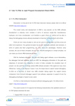
COMET PLUNGER PUMP SERVICE MANUAL INDEX
1. SAFETY INSTRUCTIONS, OPERATING PROCEDURES AND LIMITS ................. 1
1.1
Installation and Start-up Information
2. TORQUE SETTING CHART .................................................................................... 1-2
2.1
AXD Series Pump
2.2
LW/ZW Series Pump
2.3
FW/HW Series Pump
3. TROUBLE SHOOTING GUIDE ................................................................................ 2
4. MAINTENANCE SCHEDULE ................................................................................... 3
5. SPECIFICATIONS AND TECHNICAL DATA ........................................................... 3
5.1
Pump Identification
5.2
Component Identification
5.3
Technical Data and Performance
6. PUMP SERVICE GUIDE
6.1 AXD Series Pump............................................................................................................. 4-7
a. Valve Maintenance
b. Removing and Replacing Manifold
c. Seal & V-Packing Maintenance
d. Seal & V-Packing Reassembly
e. Plunger Maintenance
f.
Plunger Reassembly
g. Crankcase Maintenance
h. Crankcase Reassembly
i.
Unloader Maintenance
6.2 LW/ZW Series Pump.......................................................................................................... 8-11
a. Valve Maintenance
b. Removing and Replacing Manifold
c. Seal & V-Packing Maintenance
d. Seal & V-Packing Reassembly
e. Plunger Maintenance
f.
Plunger Reassembly
g. Crankcase Maintenance
h. Crankcase Reassembly
6.3 FW/HW Series Pump........................................................................................................ 12-14
a. Valve Maintenance
b. Removing & Replacing Manifold
c. Seal & V-Packing Maintenance
d. Seal & V-Packing Reassembly
e. Plunger Maintenance
f.
Plunger Reassembly
g. Crankcase Maintenance
h. Crankcase Reassembly
7. PUMP LIMITED WARRANTY................................................................................... 15
1
1. SAFETY INSTRUCTIONS, OPERATING PROCEDURES AND LIMITS
1.1
Start-up Information
a.
LUBRICATION: Make sure crankcase is filled with Comet Pump oil. Running this pump
without oil will cause damage and void any warranties. Change the pump oil after the
initial 50 hours of operation. Change oil every 500 hours after the initial oil change. The
oil level of the pump can be checked by removing the oil cap and inspecting the dip stick.
The correct level should fall between the min and max lines on the dip stick.
b.
WET END: The Comet Pump should never be run dry. Running the pump dry will cause
premature wear on the seals, packing and plungers. Running the pump dry for a
prolonged period of time may cause damage that cannot be repaired. Do not start a
pump with frozen water in the manifold.
c.
STORAGE: If there is a risk of freezing, run antifreeze through the pump. Empty any
extra liquid inside the pump by running the pump without water for no more than 20
seconds.
2. TORQUE SETTING CHARTS
2.1
AXD Series Pump
POSITION#
TORQUE
SETTING
1
18 FT/LB
2
33 FT/LB
3
18 FT/LB
4
18 FT/LB
1.
FLUID TO BE
USED
4.
LOCTITE 243
LOCTITE 243
3.
2.
2.2
LW/ZW Series Pump
POSITION#
TORQUE
SETTING
FLUID TO BE
USED
1
7.5 FT/LB
2
37 FT/LB
LOCTITE 542
3
4.5 FT/LB
LOCTITE 542
4
6.5 FT/LB
5
6.5 FT/LB
6
5.5 FT/LB
1.
2.
6.
3.
4.
5.
2.3
FW/HW Series Pump
POSITION#
TORQUE
SETTING
FLUID TO BE
USED
1
18 FT/LB
2
37 FT/LB
LOCTITE 542
3
7 FT/LB
LOCTITE 542
4
3 FT/LB
5
18 FT/LB
6
6 FT/LB
6.
4.
1.
5.
3.
3. TROUBLE SHOOTING GUIDE
SYMPTOMS
CAUSES
REMEDIES
The pump does not start
Air suction
Control inlet device
Irregular pressure vibration
Closed lance
Pump sucking air
Open the lance
Check that there is no water
leaking as it enters the pump
Nozzle inadequate or worn
Clean and/or replace nozzle
Worn, dirty/blocked valves
Pump sucking air
Replace check valves
Check that there is no water
leaking as it enters the pump
Blocked nozzle
Clean and/or replace nozzle
Air in pump
Pull the trigger to release air in
system
Water inlet filter blocked
Clean filter
Inadequate water supply
Make sure tap is completely open
and/or connect to a tap that has
adequate flow rate
Worn, dirty/blocked valves
Replace check valve
Worn packing
Worn nozzle
Install new seal kit
Replace the nozzle
Dirty or blocked valves
Replace check valves
Worn packing
Pump sucking air
Install new seal kit
Check that there is no water
leaking as it enters the pump
Blocked suction
Inspect filter and inlet supply
Water temperature is too hot
Max water temp must not exceed
145° F
Worn, dirty/blocked valves
Replace check valves
Water leak from head
Worn bearings
Worn packing
Replace bearing
Install new seal kit
Oil leak
Oil seals worn
Install new oil seals
Irregular pump pressure
Drop in pressure
Excessive noise
2
2.
4. MAINTENANCE SCHEDULE
OPERATION
Every 8 hours
Check oil level
Check tubes-fittings
Check & clean inlet filter
Control pump connection to the
engine
Change oil
Check suction/delivery valves
Check pump bolt and nut setting
Check regulation valve
Every 50 hours
Every 500 hours
X
X
X
X
X –FIRST CHANGE
X
X
X
X
5. PUMP SPECIFICATION AND TECHNICAL DATA
5.1 Pump Identification Model#
Positions:
a.
POSITIONS:
1.
Model#: eg.
2.
3.
4.
5.
AX D 30 20
G
1. Model:
AX:
LW:
ZW:
FW:
HW
radial axial
small frame
medium duty
heavy duty
super duty
2. RPM
D:
S:
-:
3400 RPM
1750 RPM
1450 RPM
3. GPM eg.55:
5.5 GPM
4. PSI eg. 30:
3000 PSI
5. Flange:
G:
E:
S:
Gasoline engine mounting flange ¾” or 1”
Electric Motor Mounting Flange 5/8” or 1 1/8”
Solid Shaft 24mm
3
Fig. B
Fig. A
Fig. C
6. PUMP SERVICE GUIDE
6.1. AXD Series Pump
A. Valve Maintenance
1. Using a 17mm wrench, remove the six
2.
3.
4.
5.
Fig. D
Press down firmly on the top of valve
assembly or riser tube with your finger.
(Fig. D)
6. Replace valve caps by applying LOCTITE
243 to valve cap and torque to 33 ft. lbs.
valve caps on manifold of pump. (Fig. A)
Examine the valve cap o’ring for cuts or
distortions. Replace if worn.
Using a needle nose pliers, remove the
riser tube and/or suction and delivery
check valve. (Fig B) The valve assembly
usually stays together when removing. If
the valve comes apart, use a needle nose
pliers or a reverse pliers. Remove the
o’ring and replace if worn or damaged.
Inspect the suction and delivery check
valve assembly for general wear and
replace if necessary. The valve assembly
consists of the plastic cage, spring, valve
seat, poppet and o’ring. (Fig. C) One
Comet valve kit is needed for a complete
valve change in one pump.
Replace old valves by placing assembly in
the valve chamber. Replace riser tube on
top of the check valve where necessary.
B. Removing & Replacing Pump Manifold
1. Using a 6mm allen head wrench, remove
the four head bolts. (Fig. E)
2. With the pump firmly secured, take two
medium sized flat head screwdrivers and
apply pressure to the manifold by prying
between crankcase and manifold. (Fig. F)
Work around from all sides of the manifold
evenly until it comes off of the pistons.
Keep manifold properly aligned with the
crankcase to prevent damage to the seals
and pistons.
3. When replacing the manifold, lubricate the
pistons and cylinders with grease. Evenly
press the manifold toward crankcase until
flush.
Fig. F
Fig. E
4
Fig. A
Fig. B
Fig. C
2.
C. Seals and V-Packing Maintenance
1. Remove the manifold as described in
section 6.1-B. It is possible that the seal
and brass retainer ring assembly stays on
the piston or remains in the manifold when
removing.
2. Using the packing extraction tool & slide
hammer, remove the brass retainer
ring/seal stack. (Fig. A) Remove the lowpressure seal using a needle nose pliers.
(Fig. B) Once this seal is removed, replace
with a new seal.
3. Remove the outer o’ring by taking a small
flat head screwdriver and working your way
under the o’ring and simply roll off. (Fig. C)
4. The V-packing stack can be taken apart by
hand.
3.
4.
5.
D. Seals and V-Packing Reassembly
1. Generously lubricate the parts
when
reassembling. Examine brass components
for any damage or water residue build-up.
3.
6.
Insert low-pressure seal using Comet repair
tools. (Fig. D) Place the brass retainer ring
on stand (Fig. D-1). Place tapered stainless
steel cylinder (Fig. D-2) on top of brass
retainer ring with the tapered narrow end on
the brass retainer.
Insert a new lowpressure seal, closed side facing up, on top
of tapered stainless steel cylinder so it lays
flat across the top. (Fig. E) Gently push the
seal down through the tapered cylinder using
plastic insertion tool (Fig. D-3.) Switch to
smaller diameter plastic insertion tool (Fig.
D-4) to push the seal into its seat inside the
brass retainer ring. (Fig. F)
Replace the outer o’ring by simply starting on
one side and working it into the groove.
Stack the V-packing in correct order and
firmly press assembly into the manifold.
Install a new oil seal by laying the seal into
the opening and evenly pressing it into place.
Reinstall the manifold onto the pump as
described in section 6.1-B.
5.
4.
Fig. D 1.
2.
Fig. E
Fig. F
5
Fig. A
Fig. B
Fig. C
E. Plunger Maintenance
1. Remove the manifold as described in
section 6.1-B.
2. Remove the 6mm allen bolts securing the
two halves of the crankcase. (Fig. A) There
are piston return springs energized within
the crankcase. When removing the bolts,
the two halves of the pump must be held
together with a press or something
equivalent to keep from springing apart.
3. Once all four bolts are removed, the pump
will want to spring apart due to the pressure
from the springs. (Fig. B)
4. Remove the pistons by pulling down from
the inside of the crankcase with your hand.
(Fig. C)
Fig. D
5. To service the oil seal, take a small flat
head screwdriver and apply pressure at a
slight side and downward angle. (Fig. D)
One side of the seal will pop up and can be
easily removed.
6. Inspect ceramic piston & all parts for wear.
Replace if worn. (Fig. E)
F. Plunger Reassembly
1. Slide the piston assembly through the
crankcase piston holes. (Fig. C)
Be
certain not to damage or displace the oil
seal during this process.
2. With pistons, springs & rings in place, take
the two halves of the pump crankcase and
press together aligning the four bolt holes.
Secure the two halves with the four 6mm
allen bolts. (Fig. B)
Fig. E
Fig. F
6
Fig. A
Fig. B
Fig. C
G. Crankcase Maintenance
1. Unscrew the four hex bolts and take the two
2.
3.
4.
5.
6.
H. Crankcase Reassembly
1. Assemble shaft/bearing assembly.
halves apart as shown in section 6.1-D.
There are internal springs pushing these
two sections apart. Place the pump in a
press, or something equivalent, to keep the
two halves from springing apart when the
bolts are removed. (Fig. A)
Once the crankcase is apart, the shaft and
bearings are exposed. The components fit
on top of each other in order according to
the parts breakdown manual. (Fig. B)
Remove thrust bearing, axial bearing by
hand.
Remove angled eccentric shaft by removing
6mm bolt with an allen wrench and lifting
off.
Remove the crankshaft using an industrial
press. Gently tap the end of the shaft until
shaft releases from the crankcase. (Fig. C)
The bearing usually comes out with the
shaft.
To remove the shaft from the
bearing, support both sides of bearing and
press or tap shaft out of the bearing.
Remove oil seal by working around the
edges with a small flat-headed screwdriver.
Lift out once completed. Replace the oil
seal once it is removed.
Fig. D
2.
3.
4.
5.
Stack
all of the shaft & bearing components.
Secure using the 6mm allen bolt & wrench.
Place LOCTITE 243 on the bolt before
threading. Torque to 18 ft. lbs. (Fig. D)
Insert large bearing into crankcase.
Lubricate and press into place.
Insert lubricated shaft into bearing and
press into place. (Fig. E)
Assemble the piston guide, spring, washer
& snap ring. Slide the piston assembly into
the piston holes as explained in 6.1-E.
Press the two halves of the crankcase
together compressing the springs. Secure
the 6mm bolts with an allen key. Torque to
18 ft. lbs. (Fig. A)
I. Unloader Maintenance
1. To service the unloader, simply take a
22mm wrench and remove the cartridge
just above the manifold. (Fig. F) Remove
this piece and replace it with new unloader
cartridge Comet part# 1215.0271.00
Fig. F
Fig. E
7
Fig. A
Fig. B
Fig. C
6.2 LW/ZW SERIES PUMP
A. Valve Maintenance
1. Using a 22mm wrench or socket, remove
2.
3.
4.
5.
the six valve caps on manifold of pump.
(Fig. A)
Examine the valve cap o’ring for cuts or
distortions and replace if worn.
Using a needle nose pliers, remove the
suction and delivery check valve. The valve
assembly usually stays together when
removing. If the valve comes apart, use a
needle nose pliers or a reverse pliers to
remove the remaining parts. (Fig. B)
Inspect the suction and delivery check valve
assembly for general wear and replace if
necessary. The valve assembly consists of
the plastic cage, spring, valve seat, poppet
and o’ring. (Fig C) One Comet valve kit is
needed for complete valve change of one
pump.
Replace old valves with new valves by
placing assembly in the valve chamber.
Press down firmly on the top of the valve
assembly. (Fig. D)
Fig. D
6. Replace valve caps by applying LOCTITE
243 to valve cap and torque to 33 ft. lbs.
B. Removing & Replacing Pump Manifold
1. Remove the manifold of the pump by
taking a 5mm allen head wrench and
removing the eight head bolts.
2. With the pump firmly secured, take a
medium sized flat head screwdriver and
apply pressure to the manifold by prying
between the crankcase and manifold.
Work around from all sides of the manifold
evenly until it comes off of the pistons.
Keep manifold properly aligned with the
pistons to prevent damage to the seals and
pistons. (Fig. E)
3. When replacing the manifold, turn
crankshaft of pump until the top of pistons
are closely aligned. Lubricate the pistons
and cylinders with grease and evenly press
the manifold toward crankcase until flush.
(Fig. F)
Fig. E
Fig. F
8
Fig. A
Fig. B
Fig. C
C. Seals and V-Packing Maintenance
1. Remove the manifold as described in
3. Replace the outer o’ring by simply starting
on one side and working it into the groove.
(Fig. C)
4. Stack the V-packing in the correct order
and firmly press the assembly into the
manifold. (Fig. D)
5. Install a new oil seal by laying the seal into
the opening and evenly pressing it into
place. (Fig. E)
6. Reinstall the manifold onto the pump as
described in section 6.2-B.
section 6.2-B. It is possible that the seal
and brass retainer ring assembly stays on
the piston or remains in the manifold when
removing.
2. Using the packing extraction tool, remove
the brass retainer ring/seal stack. (Fig. A)
Remove the low-pressure seal using a
needle nose pliers. (Fig. B) Once this seal
is removed, replace with a new seal.
3. Remove the outer o’ring by taking a small
flat head screwdriver and working it under
the o-ring. Simply roll off the o’ring. (Fig. C)
4. The V-packing stack can be taken apart by
hand.
E. Plunger Maintenance
1. Remove the manifold as described in
section 6.2-B.
Remove the packing
retainers if they remain on the pistons after
removing the manifold.
2. Remove the nut and washer on the end of
the piston using a 13mm wrench or socket.
3. Slide the ceramic plunger and the
remaining washer from the piston guide.
Inspect ceramic piston, o’ring and washers
for wear. Replace if necessary. (Fig. F)
D. Seals and V-Packing Reassembly
1. Generously lubricate parts with grease
when reassembling. Examine brass
components for any damage or water
residue build-up.
2. Insert low-pressure sealing working it in by
hand.
Fig. D
Fig. E
Fig. F
9
Fig. A
Fig. C
Fig. B
F. Plunger Reassembly
1. Generously grease
the piston guide.
Replace the o’ring making sure it does not
twist or roll.
2. Slide the lower washer and ceramic bushing
onto the piston guide. (Fig. A)
3. Place a small amount of LOCTITE 243 on
the piston guide threads. Replace the outer
washer and thread the nut onto the piston
guide. Torque to 4.5 ft. lbs.
6.
7.
8.
G. Crankcase Maintenance
1. Remove manifold & pistons as described in
2.
3.
4.
5.
sections 6.2-B, 6.2-E.
Remove the plastic bearing cover ring using
4mm allen wrench to unscrew the three
bolts. (Fig. B)
Remove plastic spacer and o’ring by hand.
Remove the snap ring from end of
crankshaft allowing the shaft to slide out of
the bearing. (Fig. D)
On the flange side of the pump, remove the
oil seal by piercing a hole in the surface of
Fig. D
9.
10.
11.
Fig. E
the oil seal with a flat head screwdriver.
Pry it out of the crankcase and over the
shaft. (Fig. E)
Remove the large snap ring securing the
flange side bearing into the crankcase.
Remove the small snap ring securing the
shaft to the bearing.
Using an industrial press, or something
equivalent, press out the shaft from the
side where the plastic cover was removed.
Secure the smaller bearing to the
crankcase using a vise grips, or something
equivalent, to make sure the smaller
bearing does not get pushed into the
crankcase with the shaft. (Fig. F) The
larger bearing on the flange side of the
pump will likely come out with the shaft.
Work the shaft out of connecting rods as
needed.
Remove the piston guides by pulling out by
hand.
Press the small bearing out of the crankcase
going through the larger bearing opening
and pressing out.
Fig. F
10
Fig. A
Fig. B
Fig. C
H. Crankcase Reassembly
1. Insert the piston guides by sliding them into
2.
3.
4.
5.
6. Secure the snap rings into place by securing
the bearing into the crankcase, and the shaft
into the bearing.
7. Install the large oil seal on the flange side of
the crankcase to cover the large bearing.
(Fig E)
8. Install the plastic spacer, o’ring and metal
cover. Secure the three bolts with a 4mm
allen wrench. Torque to 3 ft. lbs. (Fig F)
9. Install the large crankcase back cover by
placing the o’ring outside of the inner lip.
Secure with the four 5mm bolts and torque
to 7 ft. lbs.
the crankcase by hand. (Fig A)
Press the small bearing into the crankcase.
(Fig B)
Insert the crankshaft through the large
bearing opening, eyeing it through the
connecting rod openings. Press the end of
the shaft down into small bearing. (Fig C)
Secure the snap ring around the shaft
outside of the small bearing. (Fig D)
Slide the large bearing over the crankshaft
and press it into the crankcase.
Fig. D
Fig. E
Fig. F
11
Fig. A
Fig. B
Fig. C
6.3. FW/HW SERIES PUMP
A. Valve Maintenance
1. Using a 22mm wrench, remove the six
2.
3.
4.
5.
valve caps on manifold of pump.
Examine the valve cap o’ring for cuts or
distortions. Replace if worn.
Using a needle nose pliers, remove the
suction and delivery check valve. The valve
assembly usually stays together when
removing. If the valve comes apart, use a
needle nose pliers or a reverse pliers to
remove. (Fig. A)
Inspect the suction and delivery check valve
assembly for general wear and replace if
necessary. The valve assembly consists of
the plastic cage, spring, valve seat, poppet
and o’ring. One Comet valve kit is needed
for a complete valve change of one pump.
(Fig. B)
Insert new valve assemblies by simply
placing the assembly in the valve chamber.
Press down firmly on the top of valve
assembly. (Fig. C)
Fig. D
6. Replace valve caps by applying LOCTITE
243 to valve cap and torque to 33 ft. lbs.
B. Removing & Replacing Pump Manifold
1. Remove the manifold of the pump by
taking a 6mm allen head wrench and
removing the eight head bolts.
2. With the pump firmly secured, take a
medium sized flat head screwdriver and
apply pressure to the manifold by prying
between the crankcase and the manifold.
Work around from all sides of the manifold
evenly until it comes off of the pistons.
Keep manifold properly aligned with the
crankcase to prevent damage to the seals
and pistons. (Fig. D)
3. When replacing the manifold, turn
crankshaft of pump until the top of pistons
are closely aligned. Lubricate pistons and
cylinders and evenly press the manifold
toward crankcase until flush. (Fig D)
Fig. E
Fig. F
12
Fig. A
Fig. B
Fig. C
C. Seals and V-Packing Maintenance
1. Remove manifold as described in section
5. Reinstall the manifold onto the pump as
described in section 6.3-B
6.3-B. It is possible that the seal and brass
retainer ring assembly stays on the piston
or remains in the manifold when removing.
2. Using the packing extraction tool, remove
the brass retainer ring/seal stack. Remove
the low-pressure seal using a needle nose
pliers. Once this seal is removed, replace
with a new seal.
3. Remove the outer o’ring by taking a small
flat head screwdriver and working it out.
Simply roll off the o’ring.
4. The V-packing can be taken apart by hand.
E. Plunger Maintenance
1. Remove manifold as described in section
6.3-B. It is possible that the seal and brass
retainer ring assembly stays on the piston
or remains in the manifold when removing.
2. Remove the 15mm nut and washer on the
end of piston. (Fig. C)
3. Slide the ceramic plunger and remaining
washer from the piston guide. Remove the
o’ring by taking a small flat head screw
driver and work it off of the piston guide.
4. Inspect ceramic piston, o’ring and washers
for wear. Replace if necessary (Fig. D)
D. Seal and V-Packing Reassembly
1. Generously lubricate parts with grease
when reassembling.
Examine brass
components for any damage or water
residue build-up.
2. Insert the low-pressure seal into the retainer
ring, working it in by hand.
3. Stack V-packing in correct order and firmly
press assembly into manifold. (Fig. A & B)
4. Install a new oil seal by laying seal into the
opening and pressing it into place. (Fig. F)
Fig. D
F. Plunger Reassembly
1. Generously grease piston guide. Replace
o’ring making sure it does not twist or roll.
2. Slide the lower washer and ceramic
bushing onto the piston guide. (Fig. E)
3. Place a small amount of LOCTITE 243 on
the piston guide threads. Replace the
outer washer and thread the nut onto the
piston guide. Torque to 4.5 ft. lbs.
Fig. E
Fig. F
13
Fig. A
Fig. C
Fig. B
F. Crankcase Maintenance
1. Remove manifold and pistons as explained
2.
3.
4.
5.
6.
7.
3.
4.
in sections 6.3-A and 6.3-B.
Remove crankcase back by removing the
six 4mm allen bolts.
Remove the mounting flange by unscrewing
the four 6mm allen bolts.
Remove the side crankcase cover by
unscrewing the four 5mm allen bolts. Pry
off the cover with a flat head screwdriver.
Press out shaft from opposite flange side of
the pump. Use a socket that will fit inside
the perimeter of the end of shaft. (Fig. A)
Work the shaft out of the connecting rods
eyes. The flange side bearing will come out
with the shaft.
Remove the small bearing opposite flange
bearing by tapping it out.
5.
6.
7.
G. Crankcase Reassembly
1. Install the piston guides and connecting
rods by sliding through the piston holes in
the crankcase. (Fig. F)
2. Press the small, non-motor side bearing into
place. The inner parts of the bearing will
float until the shaft is installed.
Fig. D
8.
9.
Fig. E
Place the bearing cover into place and
secure the four bolts onto cover. (Fig. D)
Install the crankshaft by eyeing it through the
connecting rods and pressing it into the small
bearing opposite of the flange.
Install the larger tapered bearing. Press the
inner portion of the bearing onto the shaft.
Place outer portion of bearing into place and
press into crankcase using the flange
between the press and the bearing. (Fig. E)
Remove flange and measure pump for any
shims that may be needed. The flange must
not press too tightly against the bearing or
the performance of the pump may be altered.
Using a caliper, measure the distance from
the top of the bearing to the edge of the
crankcase where the flange will sit flush.
(Fig. B) Next measure inside peak of flange
and the flange portion that will sit flush onto
the crankcase. (Fig. C) The flange peak
may be taller than the distance from the top
of the bearing to the top of the crankcase.
Use the shims to make-up the difference.
Install the flange onto the pump by securing
the four bolts.
Replace the rear cover of the crankcase by
securing the six 4mm allen bolts
Fig. F
14
7. PUMP LIMITED WARRANTY
7.1 Comet Pump Limited Warranty
The Comet pump is warranted by the manufacturer to the original purchaser to be free from defects in
material and workmanship under normal use and service. “Normal use and service” means not in excess of
the recommended maximum speeds, pressures and temperatures or handling fluids not compatible with
component materials. This warranty shall not apply to any pump that has been repaired or altered to affect
the performance or reliability of the pump.
The period of Limited Warranty on AXD models shall be one year from the date of sale to the end user.
Liability of manufacturer under the foregoing warranty is limited to repair or replacement at the option of the
manufacturer of that product, which according to the manufacturer’s investigation was deemed defective at
the time of shipment. This warranty is in lieu of all other warranties, expressed or implied, including any
warranty of merchantability and/or any and all other obligations or liabilities on the part of the manufacturers.
The period of Limited Warranty on the LW, ZW,FW & HW models shall be five years from the date of
sale to the end user. Liability of manufacturer under the foregoing warranty is limited to repair or replacement
at the option of the manufacturer of that product, which according to the manufacturer’s investigation was
deemed defective at the time of shipment. This warranty is in lieu of all other warranties, expressed or
implied, including any warranty of merchantability and/or any and all other obligations or liabilities on the part
of the manufacturers.
7.2 Limited Warranty Conditions
a. Pump operation must be within the maximum RPM, discharge pressure and inlet pressure specifications.
A pressure relief valve must be properly installed in the system.
b. The pump must be operated with sufficient fluid to the manifold. Do not pump aggressive fluid that may
cause premature wear to the internal components.
c. The oil level in the crankcase must be maintained at the correct level according to Comet specifications
for proper lubrication.
d. The pump must be protected from freezing. Flush the system with propylene glycol antifreeze before
storing in freezing conditions. Use the following concentration: 14° F-25% 5°F-33% minus 25°F-50%
15