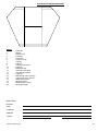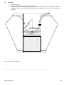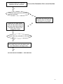
1
A U T O B AL E R Service Manual SL100/SL200 Series For Assistance or Advice Call: 02 67 345 403 or Service Line 1800 888 403 Trethewey Industries New England Highway 14 Carl Baer Circuit Deepwater NSW 2371 AutoBaler SL100/SL200 Note: When servicing a press or addressing a press problem please check the press serial and model numbers and the date of manufacture. This manual will apply to earlier models, however, there will be issues with earlier models which will not be covered by this manual, and an amendment to this manual covering earlier models is available. Please contact the press manufacturer on their service agent. To be equipped to service a problem press, the technician, before leaving to service the machine, especially where a customer has phoned with a problem, will need via the phone to establish the possible source of the problem, so as to be equipped to deal with that particular problem. However if the technician from the information given is unable to identify the possible problem, he should contact the manufacturer before leaving to ensure that the correct components and testing equipment are taken to the problem machine, thus minimising the down time of service and inconvenience to the customer. Caution: If the machine requires welding: 1. Always completely remove the electronic control units’ connections as welding may seriously damage the controller. 2. Always anchor the earth lead of the welder directly to the part being welded. 3. Clean to bare metal the position of the earth clamp. 4. Ensure that no electric or electronic wiring plastic etc is in the vicinity or the heat affected area. CUSTOMER SERVICE NUMBER: 1800 888 403 TiBMan014Rev01Aug07 2 Table of Contents 1. 2. 3. 4. 5. 6. 7. 8. 9. 10. 11. 12. 13. 14. 15. 16. 17. 18. 19. 20. 21. 22. 23. 24. 25. 26. 27. 28. Baler Check before Commissioning Commissioning of New Autobaler Installation Instructions for the Overhead Safety Canopy Oil Leaks Pressing Fingers Malfunction Press Cycles Down With Front Door Open Press Fails To Start Press Starts But Fails To Cycle Press Continually Cycles Press Noises Press Fails To Press Heavy Bales Stringing System, Procedures & Problems Bale Ejection System Press Movement On The Floor During Operation Doors Latching & Opening Adjusting System Pressure Pressure Switch Emergency Bar Operation Damper Strut Lubrication Press fails to cycle automatically Maintenance Instructions Servicing Forms Safety Procedure for Training/Training Manual Parts Listing DRAWINGS Component Identification Charts SL100/SL200 Compaction Mechanism SL100/SL200 Fingerlock Mechanism SL100/SL200 Damper SL100/SL200 SL100/SL200 Filter Assembly SL100/SL200 SL100/SL200 Facility Diagram Front Elevation Facility Diagram Plan View Hydraulic Circuit Diagram Type1 Hydraulic Circuit Diagram Type 2 Appendix TiBMan014Rev01Aug07 5 6-7 8 9-10 11 12 13 13 13 13 14 15-16 17 18 19 20 21 22 23 24-25 26 27 28-32 33-45 46-72 73-74 75-83 84-105 3 Chapter 1 Baler Check before Commissioning Trethewey Industries balers undergo a thorough quality check before they are despatched from the factory. This ensures that they are all in perfect order. Due to varying conditions during the transporting procedure the balers will require a prestart up check. The installer should be a person trained, qualified and approved by the baler manufacturers for the purpose of pre-start up and machine commissioning. When installing a baler the pre-start up check should be as follows: 1. Thoroughly check the baler for obvious damage from transport and handling. 2. Check the baler for moisture contamination. The manufacturers’ recommendation is that balers not be transported in a manner that will cause water contamination to the electrics and the electronics. 3. Check the electrical system for obvious damage 4. Check hydraulic system for oil leaks 5. Check Safety Bar 6. Insert all strings through string lock as in stringing set up in the operator’s manual 7. Bottom Door Adjustment 1. Check the Baler for Damage from Transport & Handling Walk around the baler and inspect for any damage that may have occurred during transport. If any damage has occurred record the damage found and contact the manufacturer immediately. 2. Check the Baler for Moisture Contamination If water contamination has occurred, the baler should not be connected to the power supply until the installer is fully satisfied that the moisture risk no longer exists. In case of severe water contamination dismantling of the following may be required to allow evaporation of the trapped moisture. a) b) c) d) e) f) Check the motor junction box, if moisture is present the unit must be allowed to dry before use. Solenoid valve coils. Electronic censor unit situated on the rear of the upper roppel. The electronic controller unit, to check this unit if contamination is suspected Remove the controller from the machine. Remove the entry plate from the back of the controller. If moisture is present allow to dry thoroughly if excessive water contamination had occurred to the controller unit it may require replacing with a dry unit. In many cases this is the best option, moisture in sensitive electronic components may take long periods to dry thoroughly. Attempting a start up with a moist unit may result in serious damage to the control unit. 3. Check the Electrical System for Obvious Damage 1. Check the plug unit for any damage or lose wires 2. Check the lead from the plug to the controller for damage, if in doubt use an appropriate multi-meter 3. Check the power connection units at the bottom of the controller for firm undamaged connection 4. Check the power entry to the motor junction box. If damage or a fault is suspected call a qualified electrician 5. Do not connect to a wall socket (point) that shows damage or is in poor repair. 4. Check Hydraulic System for Oil Leaks. 1. Check the fluid level in the reservoir, the oil should be showing on the dip stick. If no oil is present then add oil (awh 40) until oil is present. Caution (Do not over fill) 2. Check oil tank for transport damage. 3. Check hydraulic hoses for damage, if damaged replace hoses (check with manufacturer for correct hose type). 4. Systematically check all fittings (hose ends and fittings can be bumped during transport and location). 5. Check safety bar 1. Check for free operation 2. Check to see that bar is functioning correctly. 6. Insert all strings through string lock as in stringing set up in the operator’s manual 1. Open and close the top door several times then open the top door fully. 2. Pull each string through the lock bar and check to see that the lock bar is not cutting or damaging the string (twine). If damage is occurring the adjustment on the string lock connector may need adjustment (to adjust - undo one of the connector link bolts, rotate one revolution, reconnect and re-test). TiBMan014Rev01Aug07 4 7. Bottom Door adjustment check Situated on the right hand side of the baler on the bottom of the lower door is an adjustable link connector. A correctly adjusted door will spring open 10-20mm when pushed closed and is unlatched. On the bottom link are two hexagonal nuts. The link can be lengthened or shortened as required by adjustment of these two nuts. Note - See manual for door link adjustment. Safety 1. Location of Autobaler: a) Never place the Autobaler near any landings or elevated loading docks, unless these areas have the appropriate safety arrangements and approvals. b) Never place the Autobaler under a man hole, air conditioner, refrigeration unit, light or any position where a service technician may have occasion to work above the machine. c) Never place the Autobaler on a loading dock, close to the edge or the above landings edge. d) Never place the Autobaler in a position where unauthorised persons have access. e) Always consult an OH&S officer. 2. Area of Operation: a) Ensure that baler trolley is stored in a position away from the operator’s passageway. b) Ensure that twine rolls & twine safety cage are positioned close to the right hand side of the Autobaler to prevent tripping. If cage is provided with hooks, use these to affix cage to safety barrier. c) Ensure that electric lead is not in a hazardous position and is not left lying on the floor, particularly if there is a chance of water being on the floor. 3. Operation of Autobaler: a) Always keep hands and arms out of the Autobaler hopper during operation. b) Always, when entering the pressing chamber for re-stringing etc, wait until the motor stops and turn the key to the “Off” position. c) Never attempt to load heavy objects over the top door during the baling process, (reduce boxes of books, brochures etc to smaller quantities). d) When removing full bales from the Autobaler, always use the Auto-eject. e) When ejecting full bales, never pull on the twine in such a manner that if the twine breaks, or the knot fails, a fall will result which may cause an injury. f) Always use the baler trolley, pallet jack or fork lift to relocate full bales. g) Always be aware of door rebound when opening top or bottom doors, always stand to the side. h) Never stand in front of the pressing chamber when ejecting full bales, always stand to the side. i) Never attempt to operate Autobaler with the front door open. j) Never attempt to clean, lubricate or work in the vicinity of the cylinders during operation. SAFETY CLOTHING / FOOTWEAR a) During assembly, location and operation of the baler, safety compliant footwear must be worn. b) Firm fitting work place compliant clothing must be worn. c) Safety compliant work place gloves, hearing protection and eye protection must be worn. Always remove Autobaler key when machine is not in operation, or is unattended. Trethewey Industries recommend that the following checks be carried out:WEEKLY a) b) c) d) e) f) Check safety guards around moving parts. Are they in place? Are they damaged? Check Autobaler key switch, is it functional and in good order? Check emergency stop button, is it functional and in good order? Check safety bar, is it functional and in good order? Check power lead, is it undamaged? Is it clear of any moisture? Check Autobaler response to opening top door. Opening more then 50mm (approx 2 inches) should cause the machine to cease cycling. IF ANY OF THE ABOVE CHECKS REVEAL DAMAGE OR MALFUNCTION, THE MACHINE SHOULD BE SHUT DOWN AND THE KEY REMOVED UNTIL THE FAULT IS REPAIRED. PREVENTATIVE MAINTENANCE: a) Every 4 months, or every 500 bales, the operation of the Autobaler should be checked by a qualified person to ensure that all safety features are functioning correctly and are undamaged. b) From time to time, a qualified electrician should inspect all power leads and electrical contacts. TiBMan014Rev01Aug07 5 Chapter 2 Commissioning of a New Autobaler This is the stage where a fully functional Autobaler is handed over for use by the end-users. At the conclusion of this commissioning, the installer must be satisfied that the Autobaler will perform as specified, and that the end-users are fully conversant with the operation and the safety guidelines. Initially, the installer must be satisfied that: The Autobaler is complete, as specified by the manufacturer The Autobaler is the specific model, as requested The power source is as specified All accessories and attachments are as requested All functions of the Autobaler operate correctly The motor rotates in a clockwise direction The hydraulic oil reservoir is full There are no hydraulic oil leaks There is no damage to any safety barriers The twine lock operates efficiently There are no safety concerns regarding the location of the Autobaler A qualified electrician has checked the power source, lead and electrical contacts The installer must now: Ensure that one, or more, of the end-users are completely trained in the safe use of the Autobaler Ensure that those trained are fully aware of safety procedures associated with the safe use of the Autobaler carry out a full training session, incorporating these factors At the completion of the training session, the installer must: Complete the “Job Completion” form, detailing precisely what was delivered and accepted by the end-user Complete the “Training & Trainee Particulars” forms, detailing the names of those who attended the training session. These persons will be sent a certificate stating that they are competent to operate the particular Autobaler, as well as have the overall knowledge to train others in its operation Training the end-users should be carried out as follows: Ensure that the person who has ultimate responsibility for the operation of the Autobaler is amongst those to be trained initially. i.e. Head Storeman or Cleaner. Carry out the training, using the end-users as much as possible, from the stage of inserting the twine initially, to the removal of a full bale At all stages of the training process, make sure that those being trained are fully aware of the safety aspects associated with the operation of the Autobaler Training is to be conducted as follows: Preparation of the twine for insertion into the Autobaler Feeding of twine through the twine lock and collars Feeding of twine through hole in rear of pressing chamber Affixing of twine to cup head bolts, explaining need for double knots Placement of twine under lugs on the base of the pressing chamber Allowance for length of twine from hole in rear of pressing chamber Fixing of twine from rear wall, under lugs, up the inside of bottom door and fixed on attachment Closing of front doors and explaining of safety features i.e. Autobaler key, emergency stop button, safety bar, coded key switch and door opening cut out Explanation of electronic eye function Demonstration of operation of Autobaler with no material in pressing chamber Explanation that material should be visible above top door level prior to activation of Autobaler Feeding of material to be baled, explaining reasons for non-operation and motor cut out Explanation of “bale full” signals Demonstration on how to “tidy up” final bale Explanation on why bottom door should never be opened during baling process Tying of bale and retraction of fingers Opening of bottom door, with emphasis on possibility of rebound Placement of bale trolley and description of auto-eject function Eject of full bale, with emphasis on need for manual assistance and care to be taken by standing aside pressing chamber TiBMan014Rev01Aug07 6 1. 2. 3. 4. 5. 6. 7. 8. 9. 10. 11. 1. 2. 3. 4. 5. 6. 7. 8. 9. 10. 11. 12. Commissioning and Training Procedure Trainers and service people must always have a manual when training or attending the baler. Trainers must have all training documentations and must be completed by each trainee. Site Inspection – Ensure the baler is situated to comply with all OH&S requirements Unwrap the baler – Remove the baler from the pallet following the baler removal procedure. Remove the components from within the baler chamber attach the twine cage to the lower mesh on the right hand side – situate the hopper mesh – fit over head screen. Complete the baler pre-delivery check Commission the Baler Train the Staff Following the Staff Training Procedure Autobaler trainee material Complete the Pre-Post Installation check Return the require forms to the company – Trainee questionnaires, trainee details and all original documents are to be returned to Trethewey Industries Invoice for payment can only be processed when all the documents have been returned to Trethewey Industries. Woolworths Job Completion and Training Procedure Job Completion form MUST BE completed and stamped with the store stamp and signed by the Store Manager and the Technician. MUST PROVIDE PROOF OF DELIVERY Head Storeman to be trained as a trainer, it will be his responsibility to ensure any new staff are fully trained in the safe operating procedure. Training Manuals must be provided to all trainees. Questionnaire must be completed and correct. Statements of Attainment will only be issued if the trainee passes the test. Staff training report MUST BE Completed. Trainer to fax through copy of Training Report and Job Completion and Staff Training Reports to be posted back ASAP. Copies of the Job Completion to be attached to tax invoice when sent. Original Copies of Job Completion and Staff Training Report to be sent monthly to Tony Fattore Woolworth by Michele Lawson, with monthly summary. Supply Tony Fattore report as Service as completed, Job Completion Report will also be required. Set up excel file for service to provide with reports TiBMan014Rev01Aug07 7 Chapter 3 Installation Instructions for the Overhead Safety Canopy FITTING OF THE OVERHEAD FRAME From within the baler lift frame – the rear support legs will telescope out When the holes in the telescoping rear legs appear, slide in retaining bolts to hold the frame in position. This operation may require two people or the use of a fork lift or mechanical lifting device. Firm up the grub screws on these legs Fit the mesh sections supplied – these will only fit one way. Tighten up the grub screws in the saddles to secure the mesh tabs to the baler The mesh frames should be now securely attached to the baler frame Firm up grub screws on baler saddles locking overhead frame into position. Note: mesh hopper must be on the inside of the legs (see illustration 2) Frame should now be as the picture below, If you require further information on the fitting procedure, please contact the manufacturers on:1800 888 403 or 02 6734 5403 Fitted Overhead Safety Canopy. FITTING OF THE SAFETY CANOPY: Rear Canopy legs position Mesh mounting lugs TiBMan014Rev01Aug07 8 Chapter 4 Oil Leaks 1. 2. 3. 4. 5. 6. 7. 8. 9. 10. 11. 12. 13. Determine leak Check oil level JIC hose fittings leak O-fitting leak Suction hose leak Solenoid leak Pump leak Cylinder leak Pressure by pass valve leak Electronic switch leak Hose leak Regen leak Parts Listing If an oil leak in the hydraulic system occurs1. Determine Leak. Determine the leak point, leaks are often difficult to locate, clean oily areas and place a sheet of cardboard beneath the effected area, and observe for leaks, this may required the machine to operate for a period. 2. Check Oil Level. The level of oil in the reservoir needs to be checked, with the main cylinders closed (fingers down) check level on the dip stick, top up if required (never overfill). 3. JIC Hose Fitting Leaks. If the oil leak is from a JIC hose end fitting, tighten up the fitting on the hose end whilst holding firm the inserted male fitting. - Caution do not over tighten. 4. O-ring Fitting Ring. If the oil is coming from the base of a fitting (most hydraulic fitting on the machine are an O- ring type, check to see that the backing nut, on the fitting is tight. If this fails to correct the leak, remove the fitting and replace the O-ring seal (See Part Listing for O-ring part Number) or replace the fitting - Caution: O-ring must be fitted to the fitting correctly without damage. When the lock nut is tightened, the O-ring on the fitting must not be forced against the thread on the fitting, ensure that the fitting is screwed in sufficiently. 5. a) b) c) Suction Hose Leak. Check the suction fitting into the pump, remove the fitting and apply thread seal tape - Caution: tape must be wound onto the fitting firmly and in the opposite direction of the fitting screwing in. Tape must not come closer to the front of the fitting than 5mm or thread tape contamination to the oil system may occur. Check suction hose for damage. Tighten suction hose clamps - new clamps may be required - double clamping may be required in some circumstance (2 clamps each end). 6. Solenoid Leaks Leaks from beneath the solenoids a) Thoroughly clean solenoids before dismantling to prevent hydraulic system contamination. b) Situated on the solenoids are electrical wire sockets - before removal, carefully mark so that these go back on as they came off. (Same position). To remove the wiring cap, remove screw in cap centre. c) With Allen key remove 4 cap screws on the solenoid unit. Each solenoid unit has four oil ports each port has a small O-ring inserted (replace the O-ring if required) see: Parts List for O-ring Number. d) When reassembling ensure both surfaces are thoroughly clean - ensure O-ring are correctly fitted and in all four ports, tighten down cap screws evenly. NOTE: Solenoid unit will only fit one way (the direction should be noted before removal). 7. Pump Leak. Leak from the hydraulic pump: a) Carefully check the inlet and outlet fittings into the pump for possible leaks. b) Replace the faulty pump; return this to the manufacture or a dealer for service. 8. Cylinder Leaks. Hydraulic Cylinder Leak a) Check fittings into cylinder for possible oil leaks. b) Check welding at the base of the cylinder for cracks resulting in a leak. TiBMan014Rev01Aug07 9 c) Excessive hydraulic cylinder shaft leakage: - As the cylinders age some leakage from the seals will occur this is normal when this becomes excessive replacement of the cylinders or the fitting of the cylinder seal kit will be required. See: Parts List for cylinder numbers. 9. Pressure Bypass Valve Leak Oil leaking from the pressure bypass valve mounted to the aluminium block: a) Check to see valve is firm (or) b) Remove valve unit and replace O-rings. c) Renew O-ring on outer cap. 10. Electronic Switch Leak. Oil leaking from the hydraulic / electronic switch unit mounted to the aluminium block: a) Tighten up the pressure unit, if this fails, replace the seal. See Parts List. b) If oil is coming from the top of the switch unit from behind the wires from inside the switch unit, replace the entire switch. 11. Hose Leak. Hoses can develop leaks and fractures as a result of age or damage or a hose fault, if a leak occurs in a hose replace the hose. See Parts List for correct hose. 12. a) b) Regen Leak. Regen valve leak (Unit on cylinder) Tighten fittings Renew O-rings on O-ring fittings. Solenoid Cap Dipstick TiBMan014Rev01Aug07 Dipstick 10 Chapter 5 Pressing Fingers Malfunction Malfunction of the pressing fingers The pressing fingers are the 2 clusters of 9 fingers, one set on each side of the press. On the pressing stroke (down) these fingers come into the upper hopper through slots in walls of the upper chamber. These fingers compress the materials in the upper hopper into the lower chamber. When the compression stroke is complete and as materials are placed into the upper hopper during normal operations, these fingers return to an upper position, as these fingers return they also relax and withdraw through the slotted side walls of the hopper without disturbing the material above, when the fingers are withdrawn from the hopper they rotate, locking in a vertical position for the compression cycle. Malfunction 1 “Limp Finger Set” 1. When the press is cycled and is returning both sets of fingers are in a fully raised position (Observe that both fingers are actually standing completely up). 2. As the direction of the cycle changes from up to coming down and one finger fails to remain ridged and rotates to horizontal position the horizontal finger will then push in through the side of the hopper with no pressing effect at all. This malfunction may occur on each stroke or at random depending on the problem. Steps to remedy 1. Isolate the machine power by removing the key from the panel. (Note pressing fingers should be completely down cylinders fully closed) 2. Remove the rear mesh safety screen from the problem side of the press. 3 Locate C shaped lock. Clean from around locking system rubbish cardboard etc. 4. Earlier model presses have no bearings on the Fingerlock pivot and may simply require lubrication both on the pivot and the side contact plate, recommended lubricants (Pro-ma lube spray). Check that the lock, pivot bolt is not over tensioned. 5. Later model machine locks, pivots on sealed bearings No. 6203LU. Check lock for freeness replace bearings if required. 6. Lock is preloaded forward with a tension spring. a) Check that the spring is attached both ends b) Check that spring has full tension. When lock is manually pulled back it should snap closed positively (unbolt one end of chain to test.) 7. Attached to the rear end of lock via two shackle plated is the release chain which is also attached to the press frame via the other end. Check that the shackles are free and that chain is untangled (Note if chain becomes tangled it will shorten the length of the chain possibly breaking the chain (or the chain anchor bolts) as the press travels in the down cycle. 8. Clean the two surfaces of contact on the lock. Remove grease compressed paper etc. Roughen surfaces using a course file. (on older models only, if required) 9. See Flow Chart (Appendix 10) Malfunction 2 Correct function of the finger system, the fingers travel in a downward direction rigidly locked when the fingers have o travelled 80 of their downward path the lock chain comes into tension releasing the lock. With the locks released the finger assembly becomes limp on the return stroke, withdrawing through the side, and then rotating to the vertical position and re- locking. Malfunction 2 - Is when the finger assembly remains rigid in both directions - rigid down is correct, rigid up is a malfunction. Steps to Remedy 1. Remove key for safety 2. Check main barrel pivot for seizure a) Lubricate main pivots b) Check for string, wire etc. tangled between the moving surfaces barrel unit should rotate freely. 3 Check that the lock chain is attached both ends and working - malfunction 2 is normally caused when the lock release chain becomes detached. (one or both ends) 4. See Flow Chart Appendix 9 Malfunction 3 “Low System Pressure” One or both fingers malfunctioning in the previous chapters in finger malfunction we look at various mechanical reasons for the fingers failing to remain locked and rigid on the pressing stroke. As previously mentioned the finger units need to be raised to their maximum for the locks to engage if the fingers fail to fully extend the lock or locks may not engage which will cause the fingers to collapse on the descending stroke. Malfunction 4 “Inadequate System Pressure” Refer to system pressure chapter 13. The four main areas of Fingerlock failure in order of priority:1. Finger lock spring 2. Disconnected chain 3. Broken finger lock body 4. Frozen or damaged bearing TiBMan014Rev01Aug07 11 Chapter 6 Press Cycles Down With Front Door Open If press fingers move down with the top door open, Stop immediately and call manufacturer or safety officer The front door is equipped with a limit switch or a coded switch unit when functioning correctly it ensures that:1. The machines pressing fingers will cycle up and down while ever the top door remains closed; 2. When the top door is opened during the cycling process the pressing fingers immediately stop and require reactivating when the door is closed again; 3. When the pressing fingers are down and the front door is closed, the pressing fingers will, with some models, retract when the up or retract button is activated, the fingers returning to an up position and remaining there; 4. With the front door open under no circumstances should the pressing fingers be able to move in a downward direction. Malfunctions of door limit switch A - Pressing fingers moving down with the top door open. B - Press not cycling except in the retraction or (fingers up) and bale eject mode. “Machines fitted with a roller switch on the right-hand side” If the machines pressing fingers move in a pressing (down) direction with the top door open the most likely cause is the limit switch on the right hand side of the door not contacting correctly with the circular cam (earlier models). Later models have a switch arrangement adjacent to the controller. The recommended clearance between the limit switch roller and the cam divot is 1mm. When the gap between the switch roller and the cam divot becomes too great, the cam will not push the limit switch via the roller deep enough to activate the switch, thus allowing the machine to cycle with the door open. (Earlier models only) On the other hand if the limit switch is over adjusted with the switch roller and the cam in contact or close to contact, the machine may become unreliable or even stop cycling. With the switch activated with the door closed (as an over adjusted switch may be) the machine would only start and run in: a) When the eject button was activated b) When the up button was pressed, press would start (if fingers were down) c) Return to the top position stopping there. To Correct: 1. Close the top door 2. Adjust the limit switch in or out as required to 1mm clearance on the closest point of the limit switch roller. Securely lock in this position. Caution - do not over tighten switch lock nuts (use a mild locking agent). Using a multi-meter check switch for correct function. Switch replacement number: SL100 - SL10086 SL200 - SL20086 Replace switch if damaged or faulty 1. Using a multi-meter check the switch function. With the door closed the switch should be in closed mode - with the top door open the switch should be in an open mode. 2. Wiring check. (See appendix 8). “Balers fitted with a key coded switch on the left hand side” If the baler cycles with the top door open, check the following:1. Ensure that the coded key is securely attached to the key bar on the top door. Replace rubber mounts if required. 2. Ensure that the coded key is fully inserted when engaged. 3. Check the coded switch for contamination entry. 4. Replace the coded switch if faulty. (Appendix 7) Coded Key Bar TiBMan014Rev01Aug07 12 Chapter 7 Press Fails to Start See Flow Chart Appendix 15 Chapter 8 Press Starts but Fails to Cycle See Flow Chart Appendix 16 Chapter 9 Press Continually Cycles 1. 2. 3. The most common cause with the press continually cycling is obstructions over the censor eyes - check the eyes that they are free of obstructions clean both eyes with a soft clean rag. The press continually cycles with clean clear eyes. See flow chart Appendix 11. Eye Chapter 10 Press Noises “Press Noises” causes/solutions It is important that the press be operated in a manner that created the minimum levels of noise especially if the machine is situated in a confined space. “Possible areas of noise and their control” 1. The press is equipped with a high speed motor coupled to a two stage pump. These in combination and situation in a confined space can create excessive noise levels. A motor/pump silencing box option is available from the manufacturers or their service agents. 2. The press is emitting a high level squeal from the hydraulic system. If the squeal is constant and the press is not cycling the possible problem is the hydraulic pressure switch. See Chapter 14 for pressure switch adjustment or replacement. 3. The pressing fingers are making a loud banging sound on the down cycle. This will happen as a result of insufficient material in the press. 4. The press makes a bumping sound as the fingers rise (in the up direction). The possible cause is a faulty damper strut. See chapter 16. 5. Squeal from main pivots. This may occur during damp weather. Lubricate using (pressure pack). TiBMan014Rev01Aug07 13 Chapter 11 Press Fails to Press Heavy Bales Bale weights can vary significantly when pressing cardboard and paper, there are several factors in the materials which can contribute to this: 1. During moist weather moisture is absorbed into the materials increasing its weight and also reducing its structural strength both these factors contribute to heavier denser bales. 2. Bales pressed quickly tend to be lighter (in some cases up to 20 %) than bales which are pressed over a longer period of time, bales pressed over a longer period have a longer time for the materials to collapse and settle (repressed bales are often lighter). 3. Bales pressed from the SL100 & SL200 can vary in weight as previously stated depending on conditions and materials the SL100 will press a bale 100-140 kgs per bale and the SL200 will press a bale 200-220 kgs per bale. 4. Low System Pressure - See Chapter 13 Adjusting System Pressure. 5. Faulty or Maladjusted Pressure Switch - See Chapter 14 Pressure Switch. Light Bale Low Density Bale Problems Full Bale Light Comes on Early. This fault is not uncommon, in some cases the light may come on each time the fingers complete the pressing cycle down, regardless of how much material there is in the bale. Adjusting the Full Bale Switch a) The pressing fingers are to be right down and the main Hydraulic cylinders fully closed. Note: Be sure the cylinders are fully closed; if necessary remove some materials from beneath the pressing fingers. Check the closing mark on the cylinder shaft to be certain cylinders are fully closed. b) Locate full bale switch situated on the left hand side of the press (motor side) on the front corner. Note: The switch can be adjusted by removing lower left mesh guard. c) The full bale switch is mounted to a plate which in turn is mounted under the bearing anchor bolt. d) The switch can come out of adjustment as a result of this plate rotating, moving the switch roller away from the frame section which activates the switch (in some machines there are bolted switch activators), to see Appendix6. e) Using a lever gently rotate the plate back until the switch roller axle is a little into the brass housing, do not over travel switch. NOTE: Do not lever against the switch, the switch is very fragile and will not take any force at all. You may need to relax the bearing anchor bolt under which the plate is mounted. f) The back edge of the switch anchor plate should be parallel with the press frame bar. g) Hold the bolt head firmly and tighten nyloc nut until it is very firm. (Caution: The bolt can rotate causing the anchor plate also to rotate out of adjustment). h) The full bale switch can be finely adjusted on the full bale switch adjustment nuts. i) If the full bale switch is damaged or faulty replace .See parts list in owners manual. j) Final check. Cylinder fully closed k) Roller axle. TiBMan014Rev01Aug07 14 Chapter 12 Stringing Systems, Procedures and Problems Stringing System “Initial Stringing” (Required 3 rolls of string) Recommended twine gauge Supalash 8 (depending on bale weights) Often problems experienced with the twine system are as result of wrong procedure or incorrect twine. For the correct procedure for the initial stringing of the baler see stringing chapter in Owners Manual. 1. Position the 3 rolls of twine on the string lock side of the baler ensure that the string rolls are the correct side up and drawing from the correct end of the twine roll. 2. Burn seal the end of the twine (for the initial stringing only) 3. If the pressing fingers are down, raise the finger assembly, by activating the up button, the pressing arms will raise and stop in the fully up position. Turn key off. 4. Fully open the bottom door and the top door. 5. Situated on the top right hand side of the press hopper is a string lock bar. 6. Insert the twine from the outside through the string lock bar holes 7. Continue down with the twine and through the collar immediately below string bar see stringing chapter of owners manual. 8. String lock bar has three holes through which the three string ends are inserted from the outside, the two strings closest to the front come down the inside of the hopper and through the collars immediately below lock bar. 9. The third twine end is inserted through the hole in the string lock bar at the back position (rear of press) see twining chapter of owners manual. The rear string passes through the twine lock bar and back inside the press through the hole in the rear panel of the press. The above initial procedure is for new balers or when fitting new rolls of twine. “Stringing for each bale” 1. Take the string end (inserted through the collars and the rear door). 2. On the two side strings pull some string through the collars and tie in each string a double non slip loop. 3. Draw the strings across the baler as per to the inside of the opposite hopper wall and loop the string loop over the doomed hook. 4. Pull string down towards the bottom of the press and place the twine under plastic tab 4, then across under tab 5. 5. Repeat the procedure on both side twines. If the twine has surplus slack pull surplus through from the outside before closing the doors. 6. With the doors still open, draw the string across from the rear wall (approximately 2.4 metres). Place twine under tabs 6 and 7. Close the bottom door and bring the twine up the inside of the front door, over the top of the bottom door and attach to the square tab on the front of the bottom door, by rotating the twine several times around the tab. 7. See twining chapter in owners’ manual & Appendix 17 Before loading the Baler 1. Check that side strings are securely attached to the domed hooks, situated on the left hand wall. 2. Check that strings are under tabs securely. Loading of the Baler 1. After stringing, close securely both doors. 2. Pressing fingers are still fully raised clear of the box. 3. Load materials into the hopper over the top of the top door. 4. When the materials are level with the top of the top door. First turn on the key and secondly press down button. From this point the press will automatically cycle while ever materials bridge the censor eyes. 5. When the full bale light is illuminated remove surplus materials from above the fingers. 6. Note if excessive materials are protruding above from between the fingers a) Open top door b) Push up button pressing arms will return to vertical position and stop c) Distribute and flatten top of bale d) Close the top door and press the down button Fingers will stop on the top of the pressed material. 7. Open the top door fully. 8. Draw side strings across the top of the bale from beneath the collars. 9. Unhook the looped ends from the domed hooks. 10. Cut the strings from below the collars; join the two ends by inserting cut end through the loop pulling tight & tying off. 11. (A) Undo string from the front door tab; (B) Tie a loop in the cross string, pull tight, cut and tie off. 12. With top door still open activate up button, the finger will stand and stop vertically. 13. Open the bottom door fully and eject the bale, see bale ejection. TiBMan014Rev01Aug07 15 String Problems A String becomes detached from the domed hooks. 1. Excessive slack in the twine can cause this. Ensure that the strings are firm after stringing. 2. String loops are not sitting into the domed hood correctly in the hooks. B 1. C 1. 2. D 1. E 1. Loops tighten on the hook. Incorrect loop. The loop must be a no slip loop. i.e. double the twine end back along itself for about 300mm and tie a loop knot near the end then come back 100mm and tie another loop knot, this gives a double loop knot. See Appendix 17 illustration 2. Loop is hard to unhook when the press is full of compressed material. In the previous paragraph is an explanation on how to do a double knot. When the tension is too great to unhook simply cut the top loop when ready to tie off the bale and use the loop section between the two knots to tie the other end. String lock is cutting the twine. Twines vary in diameter especially if a twine not recommended is being used. The twine lock system is adjustable, if the twine is being cut as a result of over adjustment remove one of the bolts on the twine lock connector bar, linking the top door with the twine lock bar - lengthen the connector bar by rotating (one rotation may be sufficient depending on twine diameter). Twine damage If the twine is being damaged and the bales are coming out with loose twines, the twines are being pulled through the locking bar during the pressing operation. This will require that the adjustable link be shortened. Note if the bar is over adjusted the lock will cut or damage the twine. TiBMan014Rev01Aug07 16 Chapter 13 Bale Ejection System The way the bale is made, the way it is capped and the type of materials being pressed, can determine how difficult it will be to remove the bale from the press. Capping of the Bale After the full bale light has come on and fingers are down firmly on top of the compressed materials:1. Open the top door (only) then2. Activate the up button, the arm will rise and stay up. 3. Level the cardboard on top of the compressed material. Amounts of cardboard raised up in the centre distribute to the outer sides of the hopper- close the top door and activate down button. 4. Fingers should now be down firmly on top of the compressed material – open fully the top door only. 5. Remove any loose amounts of cardboard. 6. Unhook twines from the left hand side of the hopper. 7. With the top door fully open, take hold of twine below the collars, right hand side and draw across the bale top. 8. Cut the twine allowing enough length to go through the loop and tighten off as firmly as possible. 9. Do the same with the twine from front to back, tie a non slip loop in the back end of the twine- untie the front from the tab on the top of the bottom door, pull tight and tie off. 10. With the front top door remaining open, activate the up button fingers will rise and stay up. 11. With pressing fingers up, open the bottom door to its maximum. 12. Place transport trolley in front of the bale. 13. Activate eject button with left hand and assist bale ejection with the right hand. Difficulties in Bale Removal In the previous paragraph the importance of tying off the bale firmly was stressed, a bale tied off firmly has minimum expansion when the bottom door is released and offers less resistance in ejecting. Problems:1. When ejecting button is activated the motor starts, yet the bale fails to eject. a. Ensure that both doors are opened to their maximum. b. If eject arms are working a thud feeling should be felt on the bale. (When the machine is new, the tacky paint surface can offer some resistance, especially if the compressed material has been in the press for some length of time, creating a bonding effect. To remove such bales, may require substantial assistance from the operator by pulling firmly on top of the bale at the same time as operating the eject button, this situation will improve with use. 2. Motor fails to start when the eject button is activated:a. Ensure that the pressing fingers are raised as previously stated and that both doors are fully opened. b. Check the emergency stop button. c. Check the power light on the controller, if the power light is not on check the power supply to the controller. d. Check the press fuse. 3. When the eject button is activated the motor starts but the hydraulics on the eject fails to function. a. Check the wiring going to the eject solenoid valves, mounted on the top of the block. On the block are two solenoid values, the single ended valve operates the bale ejection system. b. Check the wiring in the valve plug unit for loose or disconnected wires. 4. A test unit is available, to test for the correct signal response from the controller - these are available from the press manufacturers or your local hydraulics service agent. 5. (1) If the motor starts when the eject button is activated (2) And the correct electronic signal is reaching the solenoid on the eject valve yet the valve fails to respond: Replace the solenoid valve unit. Remove and dismantle the valve, clean the internal working parts thoroughly in clean fuel to remove any possible contamination. Replace the solenoid valve coil. Note: If there is no signal from the controller to the valve:Check the wiring from the controller to the valve for damage or for loose or disconnected wires or loose fittings. Replace the main controller unit. TiBMan014Rev01Aug07 17 Chapter 14 Press Movement on the Floor during Operation STRUT MALFUNCTION The likely cause of press movement in locating on the floor is a faulty damper strut. See Appendix 3. Steps to check:1. Ensure that there is sufficient material in the hopper to prevent the fingers crashing on the down stroke during test. 2. As the press is cycled in the up stroke, finger assemblies, come into contact with rubber bumpers. 3. If the damper struts are functioning correctly, finger assemblies will contact the bumpers, without a bump or without making a bumping sound. If a strut is faulty, one or both of the assemblies will contact the bumpers with force; this bump force causes the press to move on the floor. Steps to correct:1. Check strut anchor points to ensure strut is connected. 2. Identify faulty strut and remove. 3. Dismantle faulty strut: Remove cap retaining screw Top of cap remove shaft assembly check that the piston unit remains well secured to the shaft Replace piston o-ring 6 Part No. (on o-ring models) thoroughly clean unit recharge o-ring models with AWH 45 grade recharge older units without o-rings with 90-160 grade amount of oil as per reassemble and refit the damper to the machine replace anchor bolts if worn bottom bolt 2½” HT top bolt 2½ x ½” HT bolt with nyloc nuts If one strut only is malfunctioning, it is still advisable to remove and service both left and right hand struts. TiBMan014Rev01Aug07 18 Chapter 15 Doors Latching and Opening The correct operation of the front lower door is an important function of the press, both for the ease of operation, safety of the operator and the performance of the press. For the bottom door to perform satisfactorily attention to lubrication is essential. See Lubrication Guide Chapter 18. 1. 2. The bottom door is interlinked with the right-hand side section of the press, as the bottom door is opened the side section of the press also pivots out, releasing the tension on the bale for easier ejection. As the bottom door is closed the above mentioned side section of the press is drawn in (hence the need to keep rotating and sliding components well lubricated. The side section movement is a result of an adjustable connection link between the front door and the base. Adjusting Front Door Latch The purpose of the link being adjustable is for adjustment on the door latch. The link can be lengthened or shortened as required to give the correct clearance between the two latch surfaces as the door closes the two flat surfaces should just contract. If the bottom door is difficult to close in the last 50 - 75mm, the last adjustable link may require lengthening (Note: a small amount of rotation can make a big difference, adjust by ¼ turns. A repeat of the procedure may be required until the door latch closes satisfactorily, and also opens well under loaded conditions i.e. Full bale). When the correct adjustment has been achieved, tighten nuts 3 on the adjuster. The connector link is secured to the press both ends by 2 X 2 ½ HT Bolts with nyloc nuts. These bolts to be done up firmly but not over tightened - replace bolts if worn. Bottom Door and Latching System Service, Operation and Adjustment Check front bottom door for soundness (welding etc) Lubricate hinges. Door Latch Adjustment 1. With the door open check the rotational freeness of the vertical door latch bar and lubricate to freeness. 2. Close the door until latch is in position. The approximate gap between the flat surfaces of the vertical bar and the press latch lugs should be approximately 1mm. 3. To adjust the door gap clearance lengthen or shorten as required, the adjustable link is situated at the bottom right hand corner of the press, if the link is over adjusted the door will not close, if under adjusted the latch surface will collide. 4. This procedure may need to be repeated until the press door opens satisfactorily under loaded conditions. 5. The adjustment link is secured to the press both ends by 2 X 2 ½ HT Bolts; these should be firm but not over tightened. Door Switch Door Adjustment TiBMan014Rev01Aug07 Door Switch 2 Door Link Adjuster Door Link Adjuster 19 Chapter 16 Adjusting System Pressure A B C D Testing and Adjusting the Hydraulic System Pressure Autobalers have a recommended system pressure of 2100psi. With time and system wear the pressure may reduce to the point of creating functional problems in the baler system. Testing System Pressure 1. A hydraulic pressure gauge with a capacity of 3000psi plus will be required. 2. To attach the pressure gauge to the baler test port A. Remove the dust cap from the baler test port fitting and attach the pressure gauge. 3. Remove one of the two wires from the hydraulic pressure switch B. “remove the wire spool fitting carefully” 4. Cycle the baler until full system pressure is reached. Adjusting the Hydraulic system pressure 1. Remove cap C from the system relief valve D 2. Insert a 3/16 Allen key into the relief valve D through the open plug port. 3. To Increase the system pressure rotate the adjustment screw in approximately ¼ turn per 500psi. 4. Systems that fail to respond to adjustment could have the following issues: a) Insufficient hydraulic oil (top oil up to recommended level) b) Coupling key sheared off – check coupling c) Hydraulic pump wear d) Inner strainer filter blocked creating pump cavitation e) Cylinder internal failure permitting oil to escape past the piston seals TiBMan014Rev01Aug07 20 Chapter 17 Pressure Switch The pressure switch plays a vital role in the operation of the machine; the pressure switch is simply an adjustable switch in the hydraulic system. The system pressure is set at approximately 2100 - 2250 psi and fixed. The pressure switch is set to fire at approximately 2000 psi, or as determined. When the cylinders reach their full stroke on the up part of the cycle full pressure is reached in the system, this causes the pressure switch to fire, sending an electronic pulse to the yellow controller. The electronic controller in turn sends the appropriate response to the solenoid valve in the hydraulic system, the solenoid valve then activates changing the flow direction of the oil path from the bottom port on the cylinder to the top port, and this change causes the cylinders now to commence closing thus commencing the (down) pressing path of the cycle. When the cylinder is fully closed full pressure is again reached, the pressure switch fires and solenoid valves are activated, oil flow to the top of the cylinder ceases and is directed to the tank. Switch Malfunction 1. If the pressure switch A is set too high the press will not cycle, it will reach the up stroke and bypass in the main system via bypass valve. 2. If the pressure switch is set too low. Low bale weight will occur. The pressing fingers also may become unreliable; as the pressing fingers are stood up progressively more pressure is required. If the pressure switch is set to low it may fire before the finger assemblies are fully up. If the fingers are not fully up the locks on the finger units will not activate and the fingers will malfunction on the down (pressing) stroke. Pressure Switch Adjustment 1. Ensure that there is sufficient (cardboard) material in the press to prevent the fingers of the unit crashing at the bottom end of the pressing stroke. 2. Activate & send pressing fingers down. 3. Turn off power key. 4. Ensure that both wires to the pressure switch are firmly connected. 5. Insert a 3mm Allan key into the pressure switch between the two wire connections. 6. Rotate the Allan key (in) clockwise ½ of one turn (leave Allan key inserted) by rotating the switch ½ of one turn this should prevent the pressure switch firing at the top end of the stoke as it normally would. 7. Start the press & activate the up button, press arms should rise & stop in the fully up position, if the switch still activates, allow the arms to travel down & stop. Rotate the Allan key further in until press does stop at the top. (Caution switch can be damaged if the key is rotated to far). 8. When the press pressing arms have reached the top position & no longer changing & coming down with motor still running. Very slowly start releasing switch adjustment by rotating inserted Allan key in an anti clockwise (out) direction until the switch activates & the arms proceed down.(Caution Beware of Moving Cylinder) 9. Stop press turn off key. 10. At the point where the switch fired, rotate Allan key (still inserted in the pressure switch) a further1/8 of one turn anti clockwise (out). 11. Test to see machine cycles reliably, remove Allan key. Pressure Switch Replacement The pressure switch will require replacement when: 1. The switch fails to respond to the adjustment 2. When oil is leaking from inside the switch 3. Behaves unreliably If the pressure switch is suspected of being faulty replace. Note: If the switch is sourced from the manufacturer it will be pre-set and should operate when fitted. If the pressure switch is not pre-set then the technician will need to follow the setting procedure as in the pressure switch adjustment. TiBMan014Rev01Aug07 21 Chapter 18 Emergency Bar Operation The emergency stop bar is situated on the top of the top door. The emergency bar is often subjected to damage from fork lifts loading skips etc. It is therefore important that its function and maintenance be understood. The bar consists of eight components: 1. Emergency bar support Bracket 2. Emergency bar 3. Connection Bolt 4. Sleeve 5. Spring 6. Washer 7. Nut 8. Limit switch The emergency bar if operating correctly, when depressed should stop the press during any part of its cycle. To recommence the cycle the appropriate button will need to be activated on the controller. Emergency bar operation 1. 2. 3. Ensure that the emergency bar bracket is firmly attached to the door, check for damage, bending etc. Check the emergency bar when depressed that is returns freely via compression spring. The purpose of sleeve is to control the down movement of the emergency bar to protect the limit switch from damage. Limit Switch Fitting Correct limit switch fitting. 1. With the emergency bar fully up and working freely the clearance between the button on the limit switch and the bottom of the emergency bar should be a minimum of 1mm. 2. Adjust the limit switch vertically in the slotted holes in the switch mounting plate so that when the emergency bar is fully depressed the emergency bar is not in contact with the plastic switch housing. 3. Operate the emergency bar, when depressed the limit switch button should be contacted and the switch make an activated click sound. When released the emergency bar should rise above the switch button. 4. Check the limit switch mounting bolts for firmness. Switch Wiring 1. The switch operates in the normally closed mode. 2. The two wires are attached to the outer terminals. Terminal 1, com and 2, NC 3. Check the wiring from the limit switch on the emergency bar to the wiring on the door limit switch for damage or short circuits. Use a multi-meter. Testing the emergency bar switch. 1. Set the multi-meter on low ohms scale, or continuity light, these should indicate a short between terminals 1 and 2 of the limit switch is not operated. Operation of the switch should remove the short circuit. (Terminals 1 and 2 outer terminals). TiBMan014Rev01Aug07 22 Chapter 19 Damper Strut The damper struts are situated on either side of the baler unit. It is essential that these be working correctly. These ensure that the finger assembly return smoothly. FULL SERVICE PROCEDURE 1. Remove the damper from the Autobaler (remove anchor bolts at both ends) 2. Remove the small cap retainer screw on the side of the damper barrel 3. Carefully remove the cap by tapping off 4. Slide out the piston assembly and take care, DO NOT DAMAGE THE SEAL 5. Replace oil with 32 grade hydraulic oil, 50mm depth in the barrel (approx 1/3 of a cup / 100ml) 6. Replace seals: Shaft seal - Ludowici R87-088 and Piston & cap seal - 2” x 3mm O’ring SERVICE CHECK 1. Raise the fingers to a vertical position and stop in that position, this can be done by pressing the retract button found on the controller 2. If a strut is working correctly, the assembly will slow 50mm before contacting the plastic stoppers 3. Leave strut attached to the baler 4. Remove the strut cap, total oil volume in each strut 100ml 5. Using a long clean rule, measure oil on top of the piston (minimum 5mm of oil depth) 6. Add 32 grade hydraulic oil if required 7. Before closing the cap, smear grease around the cap O’ring 8. Re-assemble and check for good function Fig 6 Fig 7 Fig 8 RECOMMENDED LUBRICANTS Only lubricants recommended by the manufacturer are to be used in the Autobaler. Failure to use the recommended lubricants will result in voidance of the baler warranty. Autobalers have high pressure pivot points and therefore must only be lubricated with high pressure long life lubricants. HYDRAULIC OIL: GREASE: SPRAY LUBRICANT: CASTROL HYSPIN 32 GRADE PBL 8 PBL 8 SPRAY LUBE For further details and possible supply of the recommended lubricants, Please phone:TOLL FREE: 1800 888 403 TiBMan014Rev01Aug07 OR (02) 67 345 403 23 Chapter 20 Lubrication Lubrication Chart The life and performance of the machine will be determined by how well the press is serviced and maintained. Though this applies to the whole life of the press, it is especially important during the first twelve months of the presses life. Hydraulic System Replace filter every 12 months. Where conditions are dusty, replace more often. Hydraulic Oil Oil type AWH 45 (recommended). Tank capacity SL100 25 L SL200 100L Oil Change Period Recommended oil change period every 1500 bales or every 2 years, under dusty conditions oil change will be required more often. (EACH MAINTENANCE PERIOD) 1. Upper door latch pivot, one pump of grease each service per pivot 2. Emergency bar pivots, oil pivot & ensure that the bar is working freely 3. Connector link pivots, connecting top door with rotary twine lock, Grease both ends 4. Upper door hinges, using KZD needle nose coupler, ¼ pump per coupling 5. Lower door hinges, using KZD coupler, ¼ pump per pivot 6. Side door slide plate, the side door assembly slides on this plate - grease generously 7. Connector link, an adjustable link. Grease both ends, see link adjustment for adjustment 8. Lower door latch clevis, grease lightly 9. Lower latch clevis, lightly grease 10. Secondary latch slide, grease lightly 11. Latch bar support, small lug welded to the vertical latch bar, lightly grease 12. Eject cylinder anchor points, grease lightly 13 Eject axle pivots, using KZD coupler (one pump) 14. Filter, change annually (see filter service details) 15. Lower side wall pivots, using KZD coupler ½ pump each 16. Dip stick, with the main cylinders fully closed, the oil level should be within 100mm from tank top 17. Middle side wall pivot, ½ pump per pivot using KZD coupler 18. Upper side wall pivot, ½ pump per pivot using KZD coupler 19. Upper & lower cylinder anchors, main hydraulic cylinder pivots situated both sides of the baler. Using KZD coupler, lever cylinder clevis to one side & squirt grease into pivot then lever clevis the other direction & squirt grease into the pivot. Rotate anchor pin ensuring grease has penetrated pivot. The anchor pin should turn freely. Repeat this procedure on all pivots (upper & lower, as well as on both sides). If difficulties are experienced with grease penetration, removal of the anchor pin may be required. Once removed, grease pin & inner clevis & refit, ensure that pin is fastened securely 20. Upper & lower damper anchors using KZD coupler grease upper & lower pin ensuring good grease penetration 21. Damper service (see damper service) 22. Chain shackles, grease pivots & slide lightly 23. Barrel grease nipples, 2 nipples situated on each finger barrel, 5 to 10 pumps per barrel 24. Main bearings, grease sides of bearings lightly 25. Finger lock roller, these are situated on each side of the baler, grease lightly TiBMan014Rev01Aug07 24 FULL LUBRICATION GUIDE 1. Upper latch pivot 2. Emergency bar pivots 3. Connector link pivots 4. Upper door hinges 5. Lower door hinges 6. Side door slide plate 7. Connector link 8. Lower latch pivots 1 3 2 4 5 8 6 7 9. 10. 11. 12. 13. 14. Eject Cylinder anchor points Eject axle pivot Lower side wall pivots Middle side wall pivot Upper side wall pivots Filter 13 10 10 9 12 9 14 11 15 16 19 18 15. Upper & Lower cylinder anchors 16. Upper & lower damper anchors 17. Damper service point 18. Chain shackles 19. Finger lock roller 17 16 15 TiBMan014Rev01Aug07 25 Chapter 21 Press Fails to Cycle Automatically 1. 2. Autobalers will not cycle automatically after the full bale indicator has responded; at this point the baler will only cycle manually using the cycle button. The baler will not cycle automatically if the baler active light is not flashing. The three most common faults for active light failure are as follows: a) As the baler cycles under load movement in the top door can affect the door interlock momentarily breaking the circuit and stopping the baler cycle and rendering the auto function inactive – adjust as required. b) Automatic function can also be affected by a hydraulic pressure switch problem. If the hydraulic pressure switch fails to fire at either the top or bottom end of the stroke the auto function will be negated. Pressure switch adjustment or replacement may be required. c) Automatic function can also result from the sensor failure, situated at the rear of the baler hopper is the receiver section of the eye unit. This may require replacement. Contact your local service organisation for a replacement unit or contact the baler manufacturer on: 1800 888 403 TiBMan014Rev01Aug07 26 Chapter 22 Maintenance Instructions This should include safe working procedures for carrying out all preventative maintenance & repairs This should also include any special tool requirements for maintenance. 1. SERVICING PROCEDURE Before attending a service site, the following may be required: 1. Source from the baler owner or operators the following a) When the internal services are due b) Date & time suitable to carry out the service c) An accurate location of the baler d) Whether site induction & training is required to enter the site e) What type of clothing & footwear are required f) Machine type & serial number g) Does the baler require attention i.e. repair/adjustment over & above a regular service, so that likely parts required can be taken 2. Personal Protective Equipment required a) A high visibility shirt or vest b) Regulation safety glasses c) Regulation footwear d) Hearing protection e) Hand cleaner f) Towel roll 3. Before commencing the service a) Isolate the power source from the machine b) Clean the area to be working in c) Remove the baler key & place an “out of service” sign if required d) Remove the guards relevant to a service 2. LUBRICANTS REQUIRED TO SERVICE AUTOBALERS 1. Tube of PBL (Pro-ma) long life grease 2. PBL or similar spray lubricant 3. 32 grade hydraulic oil, Note: a minimum of 20 litres is required for top up purposes in a regular service. Sufficient oil should be carried for maintenance which requires an oil change. For a complete oil change, the amount of oil required for the 100 and 200 series Autobalers is 60 litres. A container or containers will be required to deposit the used baler oil. In the likely event of an oil spill, carry a sufficient amount of oil absorbent substance to ensure that the floor area is completely oil free on completion of the job. Used oil must be disposed of via an oil recycler or in a legal manner. 3. TOOLS REQUIRED FOR A PREVENTATIVE MAINTENANCE 1. Cartridge type grease gun 2. Oil pump 3. Oil funnel 4. KZD needle nose coupler 4. BALER SPARES REQUIRED FOR A SERVICE 1. Oil filter - SL100 CR40 (AFR30C10NR/HN) SL200 CR65GN (OMTF111F10NA1/LA) 2. Pressure switch 3. Fingerlock spring, part No: SL10059/SL20059 4. Plastic twine tabs 5. Assorted high tensile bolts (2 ½” x ½” x ht nyloc) 6. Roller type limit switch (omron) 7. Cable ties 8. Spare cylinders, see parts list numbers 9. Cylinder anchor bushes see parts list number 10. Controller mount anti vibration fasteners, see parts list number 11. Spare finger lock chains, see parts list number 12. Spare damper 13. 4 amp controller fuse 14. Full bale light bulb 15. Coded key mount rubbers 16. Spare eye unit The parts listed above are the parts which may be required & recommended be carried by all authorised service agents TiBMan014Rev01Aug07 27 Chapter 23 Servicing Service Period - Every 4 months M/M = Major Maintenance every 12 months or every 660 bales Major Maintenance 1. Auto-baler service essentials 2. Replacing the Finger Lock Springs 3. Replacing the Oil Filters 4. Servicing Finger Assemblies 5. Door Adjustment Check 6. Damper Unit Service 7. Electronics 8. Service Check on Finger Locks 9. Hydraulic Check 10. Full Lubrication Guide 11. Safety Check List 12. Service Guide Lubrication Dampers Hydraulics Electrics Controller – Eye Operation Solenoid Valve System Safety Bar Operation Full Bale Indicator Operation Structural Twine System Top Door Guarding Finger Assembly Check Bottom Door General Operation Signage TiBMan014Rev01Aug07 28 FIVE AUTO-BALER SERVICE ESSENTIALS 1. CLEAN all loose material from within the balers’ upper and lower sections and behind the compaction cylinders. Caution – when cleaning around the power unit area care must be taken with wiring and wiring connectors. 2. LUBRICATE the baler in accordance with the manufactures recommendations i.e. lubricate all moving parts, upper and lower cylinder pivots, door latches and hinges, side door slide plate, hydraulic unit oil level etc. 3. Complete a safety audit form i.e.: door interlocks emergency bar, emergency stop, baler location guarding, work practices etc. 4. Check the baler function and operation. I.e.: all finger units’ functions correctly, finger units standing smoothly (check damper function) door latch operation. 5. DOOR LATCHING. Check baler door latch operation check and repair worn door latches. Check for safety of Latching and ease of operation. TiBMan014Rev01Aug07 29 2. REPLACING THE FINGER LOCK SPRINGS For good reliable service, the finger lock springs require replacement on a frequent basis. The SL100/SL200 balers have a pair of finger locks, one on each side of the baler. “Replace annually” spring part number: SL10059/SL20059 The finger lock has attached a chain via two shackles; the chain is attached to the other end of the baler structure. Attached to the finger lock unit is a tension spring, the tension spring is attached to the finger by a spring which is attached to the finger by a 3/8” bolt (see finger lock illustration) STEPS TO THE FINGER LOCK SPRING REPLACEMENT 1. Locate the finger lock assembly (Left to Right) 2. Remove the outer mesh screens 3. Ensure that the finger assemblies are down (cylinders are fully closed) 4. Release the finger lock chain on one end, this will allow finger lock to close releasing the tension in the finger lock springs 5. Remove the existing spring by rotating the upper spring hook from the top lug (use vice grip tool) 6. Unhook the spring from the bottom anchor bolt 7. Check the anchor bolt for firmness 8. Attach new spring to the bolt lug at the bottom (full loop end of spring) 9. Grip the top of the spring firmly using clamp vice grip pliers, lift and rotate spring into the top anchor lug hole 10. Re-attach chain to the finger lock 11. Check to see that springs are fully and securely attached 3. REPLACING THE OIL FILTERS It is recommended that the oil is tested annually to check for Oil contamination; Oil damage from overheating; Water ingressions from high pressure cleaning. The hydraulic system requires a filter change every third service. The filter is situated on the hydraulic tank which is situated at the side or rear of the Autobaler Filter Changing Procedure:a) Remove the three small studs on the tank; these are located on the top of the unit (see illustration 1) b) Lift filter out of the unit (Note: the unit does not require removal from the tank) c) Replace the new filter taking care with the re-assembly making sure that the filter is the correct way up (see illustration 2) d) Ensure no contamination occurs; clean well before disassembly and re-assembly e) Tighten the filter unit lid down evenly f) Run the machine and check for oil leaks Illustration: 1 Illustration: 2 4. SERVICING OF THE FINGER ASSEMBLIES The finger assemblies consist of a left and a right hand unit. 1. Check the anchor bolts on each of the main bearings, if bolts are broken replace with 2 ½ x ½ or 2” x ½“ UNC HT bolts with Nyloc nuts. 2. Machines equipped with nylon main bushes lubricate using pressure pack lubricant. 3. Check bearing pivot shaft securing pins/bolts. 4. Finger assemblies consist of finger/barrel cluster coupled to the finger frame assembly by a full length hard chrome pin, check that the pin fastening is secure. 5. Lubricate grease nipple on main barrel. 6. Check finger assembly for weld failure or fatigue. 7. Check top cylinder anchor 8. Remove one split pin from the anchor pin. 9. Remove the anchor pin- check pin and lug sleeve for excessive wear, replace the pin and bush if required. 10. Check the cylinder clevis for cracks, fatigue or wear, replace if required. 11. Lubricate pivot with lithium based grease before reassembly. 12. Dismantle and lubricate the bottom cylinder anchor, check hydraulic cylinder fittings for oil leaks. TiBMan014Rev01Aug07 30 5. DOOR ADJUSTMENT CHECK The front door on the AutoBaler is connected to the side door pivoting via an adjustable linkage. Fig 11 If a linkage assembly is incorrectly adjusted the bottom door latch can be difficult to open or close. 1. Check the linkage arrangement for damage. 2. Check that all bolts are attached and in good order, replace with a 2” X ½ “ HT bolt if required. 3. To adjust, lengthen or shorten adjustment link as required. 4. In most cases the link will require lengthening - to lengthen, release 5/8 lock nut furthermost from the press, rotate ½ turn, follow up lock nut closest to the press, tension up. If the adjuster is over length the door won’t close. A correctly adjusted doorWhen the bottom door is pushed fully closed without latching it will spring back open from 15-20 mm. Lubricate all pivot points on the linkage, door hinges and the door latch. Door Check Complete. 6. DAMPER UNIT SERVICE. The damper struts are situated on either side of the baler unit. It is essential that these be working correctly. These ensure that the finger assembly return smoothly. FULL SERVICE PROCEDURE 1. Remove the damper from the Autobaler (remove anchor bolts at both ends) 2. Remove the small cap retainer screw on the side of the damper barrel 3. Carefully remove the cap by tapping off 4. Slide out the piston assembly and take care, DO NOT DAMAGE THE SEAL 5. Replace oil with 32 grade hydraulic oil, 50mm depth in the barrel (approx 1/3 of a cup / 100ml) 6. Replace seals: Shaft seal - Ludowici R87-088 and Piston & cap seal - 2” x 3mm O’ring SERVICE CHECK 1. Raise the fingers to a vertical position and stop in that position, this can be done by pressing the retract button found on the controller 2. If a strut is working correctly, the assembly will slow 50mm before contacting the plastic stoppers 3. Leave strut attached to the baler 4. Remove the strut cap, total oil volume in each strut 100ml 5. Using a long clean rule, measure oil on top of the piston (minimum 5mm of oil depth) 6. Add 32 grade hydraulic oil if required 7. Before closing the cap, smear grease around the cap O’ring 8. Re-assemble and check for good function Fig 6 7. 1. 2. 3. 4. 5. 6. 7. Fig 7 Fig 8 ELECTRONICS - FOR DETAILED INFORMATION SEE STARLOGIXS Check the operation of the key switch and emergency stop button. See illustration 5. Check the operation of the cycle buttons. Check the door open switch. The baler must not be able to cycle down with the top door open. Check the operation of the eject function “with all doors open”. Press the eject button, eject arms will swing into the press chamber ejecting the bale, eject arms require manual retraction (i.e. press in with your foot). Note if the eject fails to eject the possible cause will be a top door limit switch - adjust the limit switch. When servicing the baler record the bale count on the bale counter situated on the controller. Illustration 5. Check the operation of the sensor units. With the press active light on place a piece of material between the sensor eyes, the motor should start and the press commences the up direction of its cycle. Check emergency / safety bar on the top door - adjust if necessary. TiBMan014Rev01Aug07 31 8. In the case of a controller failure, replace the controller unit. Illustration 5 8. SERVICE CHECK ON FINGER LOCKS Finger lock unit (see illustration 10) consists of a C shaped lock which hold the pressing assembly rigid on the down (pressing stroke) if the pressing assembly fails to remain rigid the fingers will drop and will push into the pressing chamber in an abnormal fashion. Figure 10 The most common cause of the problem is a finger unit. Initial Check: 1. The finger lock unit is sprung loaded forward by a tension spring (known as a finger lock spring); if this fails the finger lock will not function. Replace if broken or stretched. 2. Check finger lock, pivot the finger lock must pivot freely (lubricate pivot). 3. Check that no obstructions i.e. plastic twine, paper, etc are obstructing the finger function. 4. Attached to the finger lock unit via shackle plates is a chain. This chain is also attached to the body of the press by a hi-tensile bolt, if this chain is detached - reattach. Note - ensure nyloc nuts are used on attaching bolts. 5. Some older models are not equipped with a roller on the top of the finger lock, if the point of the finger lock has become worn; 6. Replace finger lock with a service unit. 7. Build up finger lock with weld and smooth off with a grinder (Note if replacing the finger lock chain, it must be the correct length - if the chain is too short it will come into excessive tension when the pressing arms are fully down causing the bolts or chain to fail. On the other hand, if the chain is too long the finger lock will not open at the correct point causing the fingers on the pressing assembly to rise in an unco-lapsed form. This can cause the finger lock unit to fail (breakage). 8. Check that the finger lock unit is functioning correctly. 9. 1. 2. 3. 4. 5. 6. 7. HYDRAULIC CHECK Check for oil leaks in the reservoir, cylinders, hoses & fittings. Check for damaged or unsupported hoses. Replace reservoir oil every 2 years - 32 grade Hydraulic Oil. Replace oil filter (CR40AN) every 12 months. Check for damage, tightness and function of the solenoid valves. Balers are equipped with a pressure test port on the aluminium valve block - older model balers 220 PSI - later models 2000 PSI. Check oil level. Oil should be showing on the dip stick - Caution - DO NOT OVER FILL. TiBMan014Rev01Aug07 32 Chapter 24 Forms Service Guide 1. Lubrication 2. Dampers 3. Hydraulics 4. Electrics 5. Controller – Eye Operation 6. Solenoid Valve System 7. Safety Bar Operation 8. Full Bale Indicator Operation 9. Structural 10. Twine System 11. Top Door 12. Guarding 13. Finger Assembly Check 14. Bottom Door 15. General Operation 16. Signage Baler Installation Procedure Conformity Document Declaration of Conformity Safety Check List Seven Essentials when Visiting a Baler AutoBaler service report Staff Training Report Pre Installation information Pre & Post Commissioning Checks Job Completion Sheet TiBMan014Rev01Aug07 33 1. Lubrication Hydraulic cylinder pivots (top and bottom) Door Hinges Use KZD Coupler attachment Side Door Pivots Use KZD Coupler attachment Side Door Slide Use KZD Coupler attachment Door Use KZD Coupler attachment Door Link Grease Finger Barrel unit (2 grease nipples per barrel) Grease Eject Bar Pivots at Rear of Press Grease Side Doorslide Plate at Bottom Comments 2. Dampers Lubricate Pivots – Top and Bottom Check Oil Level, See Oil Level Checking and Refilling Procedure Check for Leaks (replace seals) Check for Operation Comments 3. Hydraulics Check System Pressure, 2200psi (illustration 27) Check Pressure Switch Firing, 1900 psi (illustration 31) Check Hoses for Damage Check Hydraulic Oil Level, 32 grade Lubricate cylinder pivot pins, remove pins and lightly grease using long life lithium based grease Check split pins on the cylinder anchor pins, replace if required Check all hydraulic hose and pipe fittings for leaks Check hydraulic system filter, replace if required. Normal replacement period 12 months, more often in dusty conditions Comments 4. Electrics Check Wiring for Damage or Lose Unsaddled Wiring Check Power Plug and Point Check Electrics Generally Report or Repair Damaged or Dangerous Situations Comments 5. Controller Check Controller for Correct Function Check for and Report Damage Check all Fittings to the Controller for Firm Positive Connection Check Controller Anchor Screws Clean the Sensor Eye Glass Comments TiBMan014Rev01Aug07 34 6. Solenoid Valve System Check All Wiring to Valve System for Damage or Contamination, Clean Thoroughly Check Screws are Firm on Solenoid Wiring Caps Check Wires are Firm on Solenoid Wiring Caps Check Wires are Firm and Moisture Boot is Fixed on Hydraulic Pressure Switch Check and Repair for Oil Leaks Comments 7. Safety Bar Operation Check That Safety Bar Functions Correctly Check Switch For Operation or Damage Check That all Bolts and Screws etc are in Good Working Order Comments 8. Full Bale Indicator Operation Check Full Bale Light, Replace Bulb if Required (illustration 35) Check full bale limit switch situated on the left side of the baler behind the front main bearing – with the pressing fingers right down (in the box) hydraulic cylinders fully closed. At this point the full bale limit switch situated behind the bearing should be depressed until the roller axle is just out side the switch body. Adjust if required. (illustration 45) Check wiring connection to switch Clean any rubbish or contamination from the switch Comments 9. Structural Thoroughly check for cracks or failed welds or any signs of fatigue or structural damage and report Check all bolts, especially bolts attaching the main finger pivot bearings replace broken bolts with high tensile bolts Check cylinder anchor lugs for fatigue Comments 10. Twine System Check to see that the twine lock through which the twine passes does not cut the twine, adjust if required Check twine plastic clips on the baler base are in good order, replace or report Comments 11. Guarding Check that mesh guards are secure and free of damage, repair or report. Comments TiBMan014Rev01Aug07 35 12. Top Door Check latch is functioning correctly Adjust and lubricate latch Lubricate hinges Check top door limit switch if functioning correctly Check coded witch that they enter centrally, adjust if required (illustration 16) Comments 13. Finger Assembly Check Check bearing anchor point bolts (replace if required) Lubricate as mentioned in lubrication section Check centre pivot bar for secure fastening i.e. circlips etc Check finger lock operation, see finger lock service manual Comments 14. Bottom Door Difficult to close, situated at the right hand bottom of the door is a connecting and adjustment link, Adjust as required Comments 15. General Operation Report any abnormalities If the baler is moving on the floor or bumping severely as the pressing arms are standing, the cause will be in the small yellow cylinders’ situated on either side of the press. Service as in damper service if this fails to correct the bumping remove the small yellow cylinder, dismantle the cylinder and service or repair as required. Comments 16. Signage Report missing safety signage Report damaged signage Comments TiBMan014Rev01Aug07 36 Trethewey Industries Baler Installation Procedure Conformity Document Yes No Has the client agreed on a dispatch date: Has the correct model required by the client been checked to conform to his requirement Has the pre-installation form been sent to the client Has the pre-installation form been completed and returned Are there issues that require attention from the return of the preinstallation form i.e. forklift, power, transport etc What are the issues? 1. 2. 3. 4. Have these issues been addressed Has the baler arrived on site With the baler at the site and all issues addressed, has a day and time been agreed on Date: Has the number of people for training been established Number to be trained Number of People Baler Serial Number Baler Type Customer Date Officer Signature TiBMan014Rev01Aug07 37 Trethewey Industries Declaration of Conformity Training Procedure Conformity Product Type ___________________________________________________________ Serial Number ___________________________________________________________ Machine Type ___________________________________________________________ Customer Name ___________________________________________________________ Baler Location ___________________________________________________________ Date ___________________________________________________________ Conformity Declaration Service Agent manual Carried Baler Removal from Pallet Pre-commissioning Check Post Commissioning Check All Store Documents ie Woolworths Trainee Documents Trainer Material Presented Controller Set-up Baler Fit Out Pre-twine Tying the Loop Twining Twining Transverse Initial Fill Baler Start Up Automatic Operation Tidy Bale Procedure Tying Off Maintaining Twine Tension Transverse Twine Tie Off Retracting Fingers Opening Doors Situating Bale Trolley Ejecting the Bale Full Bale made Trainees Competent I hereby declare that I/we have fully complied Signed: ____________________________________________ Date: ____________________________________________ TiBMan014Rev01Aug07 38 Autobaler Service Report / Safety Check List Name/Location Baler Model Store # Date Controller # Serial # Bale Count Five Auto-Baler Service Essentials CLEAN all loose material from within the balers’ upper & lower sections & behind the compaction cylinders. Caution – when cleaning around the power unit area care must be taken with wiring & wiring connectors. LUBRICATE the baler in accordance with the manufactures recommendations i.e. lubricate all moving parts, upper & lower cylinder pivots, door latches & hinges, side door slide plate, hydraulic unit oil level etc. COMPLETE a safety audit form i.e.: door interlocks emergency bar, emergency stop, baler location guarding, work practices etc. CHECK the baler function & operation. i.e.: all finger units’ functions correctly, finger units string smoothly (check damper function) door latch operation. CHECK baler door latch operation check & repair worn door latches. Check for safety of Latching & ease of operation. Service Requirements Check top door operation, must not open more than 30mm without activating switch Check safety operation situated on the top door Check emergency stop Check key operation Check power leads for damage placement etc Check baler situation, must not be near where service is required e.g. lights Check upper & lower door catches for positive lock Check all guarding, report, refit or correct if required Report unsafe operator practices Report other areas of safety concerns Check safety signage is in good order Check twine cage placement, cage must be situated to prevent tripping Service Grease points & lubrication All moving parts Secondary latch slide Connector link Bottom door slide Lower door latch clevis Bottom door link adjustment Safety latch for lower door Chain plates Latch clevis Eject cylinder anchor point Clean & check mounts on sensor eye Good Poor Action Taken Eject axle pivot Latch bar support Emergency bar pivots All side wall rear hinges Lower 7 Upper Door hinges Damper strut pivots Cylinder pivot pins Finger Locks Safety Bar wedge Remove all material from hydraulic area, all moving parts must be free When Visiting a Baler The compacting arm assemblies must remain rigid on the first 90% of the compression stroke & fully bent on the up stroke. If not: Check the finger lock spring Check the finger lock for freeness & positive locking Check the finger lock chain for attachment at both ends Check that the pressure switch is firing in the correct range Top door security fingers must not be able to move down with the top door open Check coded key for attachment & operation Check alignment of magnetic switch on 2005 + models Older balers check limit switch on the top door hinge Check mounting of magnet switch i.e. Fasteners Is the baler operating smoothly? When the finger assembly is standing up the action must be smooth with no bumps or jar Check damper struts for attachment For operation, add 1/3 cup light oil if required Bottom door closer, must close with ease Grease all door slide Adjust the bottom door, adjust link until door closes with ease Check for oil leaks Correct the leak if present Check the reservoir oil level * Ensure the cylinders are in a closed position General check Baler operation Eject Operation Twine Tabs Structural soundness Service Compliance Declaration Complete & attach tear out section of Autobaler service booklet & return (found behind the left front panel in service pouch) Service Compliance Declaration: Service Agent Provider: Signature: Any other comments: Print Name: Position: Authorised Persons Signature: TiBMan014Rev01Aug07 Date: 39 JOB COMPLETION SHEET: CARDBOARD BALERS Store Name & No: _____________________________________________________ Purchase Order No: _____________________________________________________ Delivery Date Requested: _____________________________________________________ Date of Installation: _____________________________________________________ Planned Date of Staff Training: _____________________________________________________ EQUIPMENT SUMMARY TYPE SERIAL No’s MODEL Autobaler Autobaler: Controller: Installation & Commissioning Completion Checklist: (please tick on completion) Positioned, Installed & Commissioned (as per supply agreement) Relevant Accessories provided (as per supply agreement): 1. Cleaning Signage YES 2. Warning Signage 3. Maintenance Signage YES 4. Operators Manual 5. Cleaning Instructions YES 6. Bale Trolley 7. Bale Twine (_____rolls) YES 8. Twine Safety Cage 9. Extension Hopper YES 10. Overhead Cage Canopy Baler checked for Travel Damage 3 Phase, 20 Amp, 4 pin plug provided 3 Phase rotation checked Check all fittings for hydraulic oil leaks Limit Switches checked & functioning correctly Adequate Signage to Push Buttons as per AS1543-1985 Section 4.4.3 Electrical Cable Length is acceptable & is supported off the floor YES YES YES YES YES YES YES YES YES YES YES YES YES Comments_______________________________________________________________________ _______________________________________________________________________________ The above has taken place to my satisfaction. Store Managers Name________________________ Signature _________________________ Technicians Name___________________________ Signature _________________________ New England Highway. Telephone: 02 6734 5403 DEEPWATER NSW 2371 Facsimile: 02 6734 5433 Email: [email protected] [email protected] [email protected] TiBMan014Rev01Aug07 40 STAFF TRAINING REPORT This is to certify that on ____ / ____ / ____ the following Staff Members of ____________ __________________________________ were trained to competently & safely operate & clean the following equipment:EQUIPMENT SUMMARY TYPE SERIAL No’s MODEL Autobaler Autobaler: Controller: Traine r Name (please print) Signed Name (please print) Signed Name (please print) Signed Name (please print) Signed Name (please print) Signed Name (please print) Signed Name (please print) Signed Name (please print) Signed Name (please print) Signed The equipment was fully operational at time of training & showed no signs of fault. Comments_______________________________________________________________________ _______________________________________________________________________________ Store Managers Name________________________ Signature __________________________ Technicians Name___________________________ Signature __________________________ New England Highway. Telephone: 02 6734 5403 DEEPWATER NSW 2371 Facsimile: 02 6734 5433 Email: [email protected] [email protected] [email protected] TiBMan014Rev01Aug07 41 Pre Installation Information Company Name: ______________________________________________________________ Address: ____________________________________________________________________ ____________________________________________________________________________ Contact: ______________________________ Phone: ________________________________ Fax: _________________________________ Email: _________________________________ Autobaler Model Requested: _____________________________________________________ Office Use Only Serial Number: __________________________ Controller Number: ______________________ Delivery Date Requested: _______________________________________________________ Installation Date and Time: ______________________________________________________ Has the Autobaler Been Delivered: ________________________________________________ Installation and Training Site Assessment Request 1. Delivery: is there a 1.5 tonne fork lift available? Y/N 2. Extra delivery cost may be incurred if alternative delivery is required. 3. I would prefer to make by own deliver arrangements Y/N 4. Will any manual handling be required? Y/N 5. What distance does the AutoBaler have to be moved? 6. Will the AutoBaler be located in your Delivery Dock? Y/N 7. Is the Delivery Dock raised? Y/N 8. Is the Delivery Dock at ground level? Y/N 9. Is there any further information we should be aware of the endure the smooth installation of your Autobaler? _____________________________________________________________ __________________________________________________________________________ 10. Does the site meet all the OH&S requirements? _______________________ Y/N Comment: ____________________________________________________________________ ____________________________________________________________________________ 11. Is the AutoBaler site ready? TiBMan014Rev01Aug07 Y/N 42 12. Power Requirement, is the appropriate power available? Y/N I.e.: (415V x 20 amp x 4 pin) it is the responsibility of the site manager to ensure that the power connection capacity in the building is compatible with the baler requirements eg Circuit breaker must suit the baler AMPS 13. Is sufficient material available for training to be conducted? SL100 – 100kg material SL200 – 180kg material SL400 – 300kg material 14. Staff training: Are all staff to be trained available for the installation time requested? Y/N 15. Do you require multiple training sessions for different shifts? 16. I am aware that extra training sessions will attract a fee of $225.00 + gst, and agree to pay this cost if extra training is provided Y/N 17. A Trethewey Industries Representative will be available to conduct your training and installation at the time requested. If for any reason there are time delays ie Power or staff unavailable, please contact the office directly to reappoint prior to the installation or extra charges will apply. 18. Service Agent: Do you have a local referred service provider? 19. Please provide contact details to enable all relevant information to be forwarded to them to assist in the servicing of your Autobaler: Y/N Y/N Y/N Service agent details: Name: __________________________________________________________________ Address: __________________________________________________________________ Phone: _______________________________ Fax: ____________________________ Trethewey Industries must be notified if the site is not reads, this will enable rescheduling of the training staff, failure to do so will attract retraining charges. I confirm that the site is reads and the appropriate power as outlined above is connected and ready. I accept that if any information is not correct and the commissioning and training cannot be carried out as organized, I will be responsible for the cost incurred for the trainers’ time if they are unable to proceed or are delayed. Installation authorized on behalf of the specified company: Name: __________________________________________________________________ Title: __________________________________________________________________ Signature: __________________________________________________________________ Date: __________________________________________________________________ TiBMan014Rev01Aug07 43 Please list the names of the people to be trained in the safe operation of the AutoBaler. Groups MUST not exceed 5 people, as competency based assessment will be conducted on all trainees individually. 1. _______________________________________________________________________ 2. _______________________________________________________________________ 3. _______________________________________________________________________ 4. _______________________________________________________________________ 5. _______________________________________________________________________ TiBMan014Rev01Aug07 44 Pre & Post Commissioning Checks Company Name: ____________________________________________________________ Address: ____________________________________________________________ City: ____________________________________________________________ Contact: ________________________ Phone: ____________________________ Installation Date: ________________________ Model: ____________________________ Serial Number: ____________________________________________________________ Controller Number: ____________________________________________________________ Pre Installation Check Checks to be Carried Out 1. Check that the paler is free of transport DAMAGE 2. Check the motor rotation (clockwise) 3. The power lead is safely situated 4. Bale trolley is stored beneath the baler overhanging on the left side 5. Deposit baler wrappings and trash Fail Pass Cleared Post Installation Check Checks to be Carried Out 1. All Hydraulic cylinder fittings 2. All Hydraulic hose and pipe fittings 3. Pressure switch setting 4. System Pressure 5. Bale full switch 6. Coded upper door switch 7. Safety Bar 8. Upper & Lower Doors 9. Dampers 10. All bolts & Split pins etc 11. All electrical wiring 12. All OH&S concerns Fail Pass Cleared Comments: __________________________________________________________________ ____________________________________________________________________________ ____________________________________________________________________________ ____________________________________________________________________________ Trethewey Representative: ______________________________________________________ Signature: ____________________________________ TiBMan014Rev01Aug07 Date: _______________________ 45 Chapter 25 Safety Procedure for Training 1. 2. 3. Autobaler Location Bale trolley location, store trolley away to prevent trip hazard or injury. Twine cage correctly attached and twine placed in cage. Point out safety devices:a) Safety bar operation b) Emergency stop button c) Key switch d) No reaching into baler e) No standing or climbing on the baler f) Turn the baler off when unattended g) Care and position when ejecting baler h) Importance of reading and observing all safety instructions i) Bale location in approved designated area. MACHINE OPERATION 1. Motor rotation check. To test, press retract button, if fingers go up rotation is correct. 2. Fitting of upper mesh hopper 3. Location of twine cage 4. Initial stringing 5. Complete stringing 6. Double knot and why? Twine under left tab then under right tab 7. Transverse twine, length, fitting etc 8. Bottom door closing 9. Twine (transverse) front door (tie off) 10. Close top door 11. Place flat cardboard in base prior to loading. 12. Initial loading to top door height, to prevent fingers banging in empty chamber. 13. Initial starting of press 14. Explain eye location and function 15. Continue to load 16. Large boxes should be loaded during the first 75% of capacity, for the last 25% load flat boxes to create a flat cap 17. Red light illuminates 18. Cycle several times to level top 19. Remove excess if required 20. Place cap on bale 21. Open top door, explain door switch safety 22. Always turn key off or press Emergency stop to neutralise unit 23. Explain how opening top door releases twine via the twine lock 24. Unlock twine from left hand hooks 25. Pull twine across from right hand side 26. Cut to correct length 27. Tie off 28. Pull transverse twine across and tie loop 29. Twine from tab to loop and tie off 30. Close top door 31. Turn on system, press retract button 32. Open bottom door 33. Place bale trolley 34. Eject bale 35. Wheel away Bale Trolley 36. Restring baler FINISHING OFF THE BALE When full bale light comes on OR Remove excess TiBMan014Rev01Aug07 1. 2. 3. Remove excess material from above the pressing fingers Place top cap Press cycle button 1. 2. 3. 4. Stand fingers up, press retract Remove excess Place cap Press cycle button 46 Autobaler Trainee Particulars (Kit) Company: ___________________________________________________________________________________ Address: ___________________________________________________________________________________ ___________________________________________________________________________________ ___________________________________________________________________________________ Trainee Name: ___________________________________________________________________________________ (Print Clearly in Capitals) Address: ___________________________________________________________________________________ ___________________________________________________________________________________ ___________________________________________________________________________________ Phone No: ___________________________________________________________________________________ Employer: ___________________________________________________________________________________ Date of Training: ____________________________________________________________________________ Autobaler Model Trained To Use: _____________________________________________________________________ I, ________________________________________________________________ (Trainer) witnessed the competency of _____________________________________________________ in the safe competent use of the Autobaler Model __________________________________________________and I received a copy of the Training Manual. I hereby validate this assessment. Signed (Trainer): ____________________________________________________________________________ Date ____________________________________________________________________________ Signed (Trainee) ____________________________________________________________________________ Date ____________________________________________________________________________ Special Comments ____________________________________________________________________________ ________________________________________________________________________________________________ ________________________________________________________________________________________________ ________________________________________________________________________________________________ ________________________________________________________________________________________________ ________________________________________________________________________________________________ ________________________________________________________________________________________________ TiBMan014Rev01Aug07 47 Trainee Exam Questions (Autobaler 100/200 Series) 1. If the baler is in a public access area and the baler will be unattended for a long period, what precaution for public safety should you take: a. Sit and watch the baler……………………………………….. b. Remove the key……………………………………………….. c. Do nothing……………………………………………………… 2. What function does the retract button have: a. General operation……………………………………………… b. Cycles the baler………………………………………………… c. Raises the fingers only………………………………………… 3. The purpose of the safety bar is: a. To do chin ups………………………………………………….. b. For emergency stopping……………………………………….. c. No particular use………………………………………………... 4. Through which holes in the twine lock bar would you insert the twine: a. One hole only……………………………………………………. b. Two holes only…………………………………………………… c. All holes…………………………………………………………... 5. When twining the baler at what position should the baler fingers be: a. Right down……………………………………………………….. b. Half way down……………………………………………………. c. Fully up……………………………………………………………. 6. What is the purpose of the plastic tabs on the base (floor) of the baler: a. Decoration………………………………………………………… b. Place twine beneath……………………………………………... c. Structural………………………………………………………….. 7. The last 10 - 20% of the bale, how would you place flattened material: a. On its edge………………………………………………………... b. Anyway……………………………………………………………. c. Flat in the baler…………………………………………………… 8. Tying of the finished bale should be done with the: a. Fingers up (retracted)…………………………………………….. b. Fingers half way…………………………………………………… c. Fingers right down………………………………………………… TiBMan014Rev01Aug07 48 9. Opening of the top door, I should: a. Open it the best I can…………………………………………….. b. It doesn’t matter…………………………………………………… c. Grip the handle firmly…………………………………………….. 10. Ejecting the bale, I should: a. Stand aside and hold finger on button………………………….. b. Push button and walk away……………………………………… c. Push button and stand in front of bale………………………….. 11. Where should the bale transport trolley be stored when not in use: a. Under the right hand side………………………………………… b. Under the left hand side………………………………………….. c. Anywhere…………………………………………………………... 12. Real heavy objects i.e. boxes of magazines etc. How should I load them into the baler: a. Over the top door………………………………………………… b. Open the top door……………………………………………….. c. The best I can……………………………………………………. 13. If the baler operates with the top door open, I must: a. Continue as normal……………………………………………….. b. Shut the machine off, remove the key and place out of order sign………………………………………………………………….. c. Take care…………………………………………………………… 14. Was the knot test passed? TiBMan014Rev01Aug07 Yes No 49 AUTOBALER Full Bale Light Bale Counter Safety Bar Twine Lock Key Emergency Stop Key Bar Control Panel Upper Door Handle Lower Door Handle TRAINER MATERIAL TiBMan014Rev01Aug07 50 AUTOBALER TRAINER MATERIAL INDEX 1. 2. 3. 4. 5. 6. 7. 8. 9. 10. 11. 12. 13. 14. 15. 16. 17. 18. 19. 20. Controller Set Up Baler Fit Out Initial Set Pre-Twine Tying the Loop Twining Twining Twining Transverse Initial Fill Baler Start Up Automatic Operation Tidy Bale Procedure Tying Off Maintaining Twine Tension Transverse Twine Tie Off Retracting Fingers Opening Doors Situating Bale Trolley Ejecting the Bale Baler Serial Number Date Customer Address Trainer TiBMan014Rev01Aug07 Signature 51 1. Controller Operation 1. 2. 3. 4. 5. 6. 7. Turn the key on – power light on Engage coded key bar – door open light on. Disengage emergency stop key rotation Cycle button to cycle Retract button to raise fingers only Eject must be held in to eject Red light and beeper full bale indicators Trainer Signature of compliance: ___________________________________________________________________________ TiBMan014Rev01Aug07 52 2. Set Up 1. 2. 3. 4. Remove The Wrapper. Cut The Straps. Remove all items from within the baler. Following the lifting directions, remove the baler from the pallet, Chapter 5 in manual. Trainer Signature of compliance: ___________________________________________________________________________ TiBMan014Rev01Aug07 53 3. Baler Fit Out 1. 2. 3. 4. 5. Fit the mesh hopper and canopy, Chapter 4. Position the twine cage to the baler side. Situate the baler trolley. Plug in baler power socket, motor must rotate clockwise. Ensure all grub screws holding the mesh hopper and canopy are tight. 1 5 5 5 5 5 2 3 Trainer Signature of compliance: ___________________________________________________________________________ TiBMan014Rev01Aug07 54 4. Initial Set 1. 2. Turn on power, engage code key bar, press retract button to stand fingers up. Draw each twine from centre of twine roll. NOTE twine roll must be right way up. 3. Heat seal twine end or use tape around. 4. Open baler doors fully, check twine holes are fully open. 4 1 2 Trainer Signature of compliance: ___________________________________________________________________________ TiBMan014Rev01Aug07 55 5. Pre-Twine 1. 2. 3. Insert sealed twine end through open hole in twine lock bar. Front two twine on inside of the baler chamber and insert through eyelets (collars). Rear twine in rear twine lock hole and down the back outside and into chamber through hole in back. 1 3 2 Trainer Signature of compliance: ___________________________________________________________________________ TiBMan014Rev01Aug07 56 6. Tying the Loop 1. 2. Tie double loop in twine ends (side twines only). Take looped ends across and hook onto hook on opposite side. 50-75mm 50-75mm Trainer Signature of compliance: ___________________________________________________________________________ TiBMan014Rev01Aug07 57 7. Twining 1. Take twine down and hook under plastic tab directly below. Trainer Signature of compliance: ___________________________________________________________________________ TiBMan014Rev01Aug07 58 8. Twining 1. Take side twines across under the tab on the right hand side. 2. Surplus slack twine inside, pull out from the outside. 2 1 Trainer Signature of compliance: ___________________________________________________________________________ TiBMan014Rev01Aug07 59 9. Twining Transverse 1. 2. 3. 4. 5. 6. 7. 8. 9. 10. Twine from rear Pull through two stretched arms length (3.5m). Place twine under rear tab then forward under front tab. Hold twine in left hand to left side. Close bottom door with right hand. Bring twine over the top of the bottom door from the inside. Twist twine end around the tab twice and bring end into slot. Latch bottom door. Twine end about halfway down the front door. Close top door. 1 7 9 3 Trainer Signature of compliance: ___________________________________________________________________________ TiBMan014Rev01Aug07 60 10. Initial Fill 1. Throw in material until visible. 1 Trainer Signature of compliance: ___________________________________________________________________________ TiBMan014Rev01Aug07 61 11. Baler Start Up 1. 2. 3. 4. With material visible :Turn on baler. Press in coded key bar. Press cycle button marked cycle. Note: If baler is cycled with no or little material in the hopper, the baler may make a sharp clunk (this will not damage the baler). 2 1 Trainer Signature of compliance: ___________________________________________________________________________ TiBMan014Rev01Aug07 62 12. Automatic Operation 1. 2. 3. 4. 5. 6. Active light will flash after cycle button has been activated. When loading baler, direct material evenly and towards censor eye to activate the baler. Throw full boxes in any time through the cycle path. Large boxes, throw these in the first 50% of the bale. Flattened cardboard on its flat. (Horizontal) DO NOT Overload, one person at a time. 2 1 Trainer Signature of compliance: ___________________________________________________________________________ TiBMan014Rev01Aug07 63 13. Tidy Bale Procedure 1. 2. 3. 4. Last 10% of bale, flattened material on flat. When full bale light comes on:Remove excess materials by cycling manually by pressing cycle button (several cycles). For neat top add large flattened material and manually cycle by activating cycle button. 5. NOTE: Baler will not cycle automatically when full bale light and indicator are activated 2 4 1 Trainer Signature of compliance: ___________________________________________________________________________ TiBMan014Rev01Aug07 64 14. Tying Off 1. 2. 3. 4. Open the top door Remove any loose materials from above the fingers. Unhook the twines on left side by pulling on the twines then lifting of the hook or if very tight cut top loop. Pull twine across from right hand side from beneath the eye collars and cut where loop touches left hand side wall. 3 4 Trainer Signature of compliance: ___________________________________________________________________________ TiBMan014Rev01Aug07 65 15. Maintaining Twine Tension 1. 2. 3. 4. 5. Loop through Pull tight With left hand hold tension by gripping the twine on the loop Tie off twine. Repeat on both twines. 1 2 Trainer Signature of compliance: ___________________________________________________________________________ TiBMan014Rev01Aug07 66 16. Transverse Twine Tie Off 1. 2. 3. 4. 5. Pull transverse twine through the hole 100mm and cut. Lower cross twine end, tie a loop as in side twines, see illustration. Undo twine off front tab. Pass loose end through loop and pull tight and tie off. NOTE Pressing fingers must be down and on the top of the bale when tiring off the bale. 1 2 3 Trainer Signature of compliance: ___________________________________________________________________________ TiBMan014Rev01Aug07 67 17. Retracting Fingers 1. 2. 3. 4. Close top door. Press in key lock bar. Turn on power- release the emergency knob. Press button marked retract. 4 3 Trainer Signature of compliance: ___________________________________________________________________________ TiBMan014Rev01Aug07 68 18. Opening Doors 1. 2. 3. 4. Open top door. Attach rebound chain to bottom door on the last link. Open bottom door latch, unlock rebound chain. Fully open door. Note: Never attempt to open the bottom door with the pressing fingers down. (They must be retracted in fully up position). 3 Trainer Signature of compliance: ___________________________________________________________________________ TiBMan014Rev01Aug07 69 19. Situating Bale Trolley -WITH DOORS FULLY OPEN-_ 1. Situate bale trolley:2. Central to the baler. 3. Out 75mm from contact. 4. Roll away from baler direction. 1 2 Trainer Signature of compliance: ___________________________________________________________________________ TiBMan014Rev01Aug07 70 20. 1. 2. 3. 4. 5. 6. 7. Ejecting the Bale All doors fully open and bale trolley situated. Stand to the left of the bale area. With right hand, grip the left cross twine. Pull firmly, at the same time pressing and holding the eject button until the bale is firmly on the trolley. Roll bale away on the trolley. Push bale sideways off trolley to unload. Start again at step four – Initial Set. Note: Push eject arms back in using foot 5 4 1 2 Trainer Signature of compliance: ___________________________________________________________________________ TiBMan014Rev01Aug07 71 SAFETY ESSENTIALS 1. Before commencing the baling process ensure that the bottom door is latched correctly to prevent the door bursting open during process. 2. Never climb onto the baler from any side or reach in during operation or stand on elevated objects. 3. When ejecting the bale stand to one side to prevent injury form the ejecting bale. 4. Always place the bale transport trolley centrally to the bale to prevent bale side roll. 5. On inclines, chock bale trolley to prevent run away 6. Use only the safety knife for twine cutting. 7. To prevent strain injury ensure that the doors and latches open freely – lubrication may be required 8. Remove baler key if in a safety sensitive zone. 9. Never operate a faulty machine tag out and call 1800 888 403 10. Autobaler operators must be licences to legally operate Autobalers TiBMan014Rev01Aug07 72 Chapter 26 Parts Listing Component Power Pack Unit Electric Motor Bell Housing Pump Pump Coupling Coupling Spider Coupling Motor Key Coupling Pump Key Coupling Grub Screws Main Valve Block Main Solenoid Unit Eject Solenoid Unit Solenoid Coils Solenoid Coil Caps Bypass Valve Unit Test Port Unit Pressure Switch Unit Dip Stick Filter Unit Filter Cartridge Filter Fitting In Filter Fitting Out SM023 Power Pack Acorn Nuts Motor Fastening Studs Hydraulic Hose Bottom Left Hydraulic Hose Bottom Right Hydraulic Hose Top Left Hydraulic Hose Top Right Eject Hose Delivery Eject Hose Return Regen Unit Isolating Switch Control To Is Cable Main Cable 4 Pin Plug Electrical Fittings Electrical Fitting Finger Frame Finger Frame Bearing Finger Frame Bearing Block Finger Frame Block Bolts Bearing Axle Axle Retainer Bolt Finger Unit Left Hand Finger Unit Right Hand Finger Unit Axle Finger Axle Retainer Bolt Finger Lock Right Hand Side Finger Lock Left Hand Side Finger Lock Shackles Finger Lock Shackle Bolts Finger Lock Chain 1. Finger Lock Chain Bolt 2. Finger Lock Chain Bolt Finger Lock Bearing Finger Lock Roller Finger Lock Roller Axle Finger Lock Spring Finger Lock Spring Anchor Bolt TiBMan014Rev01Aug07 Part Number for SL100 SL10001 SL10002 SL10003 SL10004 SL10005 SL10006 SL10007 SL10008 SL10009 SL10010 SL10011 SL10012 SL10013 SL10014 SL10015 SL10016 SL10017 SL10018 SL10019 SL10020 SL10021 SL10022 SL10023 SL10024 SL10025 SL10026 SL10027 SL10028 SL10029 SL10030 SL10031 SL10032 SL10033 SL10034 SL10035 SL10036 SL10037 SL10038 SL10039 SL10040 SL10041 SL10042 SL10043 SL10044 SL10045 SL10046 SL10047 SL10048 SL10049 SL10050 SL10051 SL10052 SL10053 SL10054 SL10055 SL10056 SL10057 SL10058 SL10059 SL10060 Part Number for SL200 SL20001 SL20002 SL20003 SL20004 SL20005 SL20006 SL20007 SL20008 SL20009 SL20010 SL20011 SL20012 SL20013 SL20014 SL20015 SL20016 SL20017 SL20018 SL20019 SL20020 SL20021 SL20022 SL20023 SL20024 SL20025 SL20026 SL20027 SL20028 SL20029 SL20030 SL20031 SL20032 SL20033 SL20034 SL20035 SL20036 SL20037 SL20038 SL20039 SL20040 SL20041 SL20042 SL20043 SL20044 SL20045 SL20046 SL20047 SL20048 SL20049 SL20050 SL20051 SL20052 SL20053 SL20054 SL20055 SL20056 SL20057 SL20058 SL20059 SL20060 73 Finger Lock Main Axle Finger Lock Axle Grub Screw Finger Lock Split Pin Finger Lock Washer Eject Frame Eject Bearing Block Eject Bearing Bolts Eject Finger Eject Hydraulic Cylinder Eject Hydraulic Fitting (Cylinder) Eject Guard Eject Guard Flap Eject Anchor Pin Twine Lock Bar Twine Lock Connector Twine Lock Bolt Twine Lock Spring Connector Twine Lock Bar Split Pin Emergency Stop Bar Emergency Bar Bolt Kit Emergency Bar Spring Coded Key Bar Insert Coded Key Anchor Tab Coded Key Bolt Kit Coded Key Coded Key Switch Upper Door Handle Upper Door Handle Grip Upper Door Handle Bolt Kit Main Upper Door Unit Upper Door Studs Upper Door Hinge Pins Lower Door Unit Vertical Latch Unit Lower Door Hinge Pins Lower Door Link Unit Link Unit Bolts Main Frame Hinge Pins Main Frame Hinge Bushes Front Upper Left Hand Cowl Front Upper Right Hand Cowl Rear Upper Left Hand Cowl Rear Upper Right Hand Cowl Lower Right Hand Front Cowl Lower Left Hand Front Cowl Lower Left Hand Rear Cowl Lower Right Hand Rear Cowl Side Upper Mesh Lower Right Hand Side Mesh Unit Lower Left Hand Side Mesh Unit Lower Mesh Hinge Units Side Mesh Upper Cover Strips Side Mesh Lower Cover Strips Canopy Unit Canopy Legs Upper Mesh Unit Plastic Twine Tabs Main Seal Hydraulic Cylinders TiBMan014Rev01Aug07 SL10061 SL10062 SL10063 SL10064 SL10065 SL10066 SL10067 SL10068 SL10069 SL10070 SL10071 SL10072 SL10073 SL10074 SL10075 SL10076 SL10077 SL10078 SL10079 SL10080 SL10081 SL10082 SL10083 SL10084 SL10085 SL10086 SL10087 SL10088 SL10089 SL10090 SL10091 SL10092 SL10093 SL10094 SL10095 SL10096 SL10097 SL10098 SL10099 SL100100 SL100101 SL100102 SL100103 SL100104 SL100105 SL100106 SL100107 SL100107 SL100109 SL100110 SL100111 SL100112 SL100113 SL100114 SL100115 SL100116 SL100117 SL100118 SL100119 SL20061 SL20062 SL20063 SL20064 SL20065 SL20066 SL20067 SL20068 SL20069 SL20070 SL20071 SL20072 SL20073 SL20074 SL20075 SL20076 SL20077 SL20078 SL20079 SL20080 SL20081 SL20082 SL20083 SL20084 SL20085 SL20086 SL20087 SL20088 SL20089 SL20090 SL20091 SL20092 SL20093 SL20094 SL20095 SL20096 SL20097 SL20098 SL20099 SL200100 SL200101 SL200102 SL200103 SL200104 SL200105 SL200106 SL200107 SL200108 SL200109 SL200110 SL200111 SL200112 SL200113 SL200114 SL200115 SL200116 SL200117 SL200118 SL200119 74 Chapter 27 Drawings TiBMan014Rev01Aug07 75 TiBMan014Rev01Aug07 76 TiBMan014Rev01Aug07 77 TiBMan014Rev01Aug07 78 TiBMan014Rev01Aug07 79 TiBMan014Rev01Aug07 80 TiBMan014Rev01Aug07 81 TiBMan014Rev01Aug07 82 TiBMan014Rev01Aug07 83 TiBMan014Rev01Aug07 84 Chapter 28 Appendix Contents 1. 2. 3. 4. 5. 6. 7. 8. 9. 10. 11. 12. 13. 14. 15. 16. 17. Fingers Valve Block Damper Door Link Bale Eject Full Bale Switch Door Switch Adjust Electronic Wiring Diagram Finger Limp Flow Chart Finger Remaining Rigid Flow Chart Continuous Cycling Flow Chart Excessive Vibration Flow Chart Low Hydraulic Pressure Flow Chart Lower Door Closing Problem Press Fails to Start Press Fails to Cycle Twining Appendix 1 86 Appendix 2 SL100 Valve Block SL200 Valve Block 87 Appendix 3 Damper 88 Appendix 4 Door Link Adjuster Door Link 89 Appendix 5 Eject 90 Appendix 6 Full Bale Switch 91 Appendix 7 Door Switch 92 Appendix 8 93 Appendix 9 Fingers fail to remain rigid on the way down Is the system pressure 2200psi Yes Is the pressure switch firing between 1950-2000 No Adjust system pressure No Replace / adjust switch Yes Check system pressure and replace pressure switch No Check system pressure and replace pressure switch No Replace finger lock spring Yes Are both sides failing to remain rigid on down stroke No One side only is failing Yes Are finger lock springs on both sides and working Yes Is finger lock in good condition, Eg bent or broken No Replace finger lock unit Yes Is the finger lock lazy and failing to come forward and lock Yes Are finger lock bearings in good No working order Replace finger lock bearings Yes Continued Next Page 94 Yes With the pressing arms right down (cylinders fully closed), remove the chain connecting the finger lock to the baler. The finger lock unit should snap forwards freely and lock over the finger unit abutment. Caution, when re-attaching the chain, ensure that the chain is not twisted and is securely and firmly attached to the baler body. SAFETY - Before removing the guards to service the finger lock unit, isolate the power and remove the key. Illustration 1 Illustration 2 Correctly locked finger unit on descending stroke Correctly broken finger unit on ascending stroke Appendix 10 95 Pressing fingers are rigid and unbroken on the up stroke See illustration 2 for correct function Yes Are both sides rigid and unbroken on the up stroke Yes Is the bale still being fed with material after the full bale indication has sounded Adjust the full bale switch. The full bale switch should activate when the hydraulic cylinders are 25mm from being fully closed Or No Is one side only unbroken on the way up Yes Is the finger lock chain still attached both ends (one end to the baler body, the other end to the finger lock) Yes Call the Service Number - 1800 888 403 96 Appendix 11 Does the baler cycle continuously without material over infra red eye Yes Are eyes clean and clear of contamination No Using soft cloth, clean eyes Yes Is the eye unit at the rear firm and vermin free No Firm up bolts and spray for vermin No Realign the controller and securely fasten the controller Yes Is the controller unit firmly attached to the baler Yes Are one or both fingers assembly units Yes bumping hard when standing up No Check for damaged or broken wires to the eye Yes Replace eye unit at the rear of the baler Does the baler cycle continuously without material over infra red eye Using soft cloth, clean eyes Firm up bolts Yesand spray for vermin Is the eye unit at the rear firm and vermin free After adding cup hydraulic oil to Realign the½controller and securely the damperfasten is it still on that thebumping controller side cylinders on each Is the small damper side securely attached both ends Are one orYes both fingers assembly units bumping hard when standing up Is the small damper cylinders on each side Service securely or replace the damper unit attached both ends Call Service Hotline: 1800 888 403 97 Appendix 12 Is the baler moving on the floor Yes Does the baler make a sharp banging or bumping sound when the finger assemblies are standing up on one or both sides? Yes Are the small yellow cylinders situated on each side adjacent to the large cylinders securely attached both ends No Re-attach, using only high tensile boils Yes Top up oils in small Dampers. Remove the small screws holding the cap and slide up the shaft and add ½ cup of hydraulic oil and cycle several times. Are the finger assemblies still bumping hard. Yes Service or replace damper unit Call service hotline: 1800 888 403 98 Appendix 13 Does the baler fail to compact heavy bails and stand the finger units up reliably Yes Is the system pressure @ 2200 psi No Adjust the system pressure Yes Check the reservoir level Check the pressure switch firing at 1950 2100 Yes Check the motor / pump coupling for sound connections Check the system bypass valve, replace O’rings Check the suction hose for cavitations Yes Check the pump for soundness Check solenoid valves for contamination or seal damage Yes Check regeneration system for contamination or seal failure Yes Check hydraulic compaction cylinders for piston leakage Call Service Hotline: 1800 888 403 99 Appendix 14 Is the bottom door difficult to close and open? Yes Have the hinges and bottom slide been lubricated No Lubricate using spray lubricant on hinges and grease on slide No Loosen until these rotate freely Yes Do the pivot bolts on the adjustable door link at the bottom of the door rotate freely? Yes Does the bottom door latch bar collide with the latch lugs Yes Release the inner lock nut on the adjustable link at the bottom and shorten by rotating outer lock nut one rotation per time, lock firmly No Note Does the bottom door jam up on the left hand side? Over adjustment will also create problems closing No Does the vertical latch bar rotate freely? Yes Lengthen the bottom door link on the adjuster by one turn No Yes Using penetrating fluid or oil to free latch bar Is there damage on the door or latch system? Call Service Hotline: 1800 888 403 100 Appendix 15 Is the Power Socket Inserted? No Insert the power socket Yes Is the supply switch turned on? No Turn on the supply switch Yes Check power supply to wall socket Turn on baler isolating switch Release emergency stop button Turn on baler key Is the balers red power light illuminated? Yes No Check controller fuse (Note: Correct value fuse must be fitted see starlogix manual) Call 1800 888 403 Check electrical leads to motor Check power connections on controller Change controller unit or control PCB Call 1800 888 403 101 Appendix 16 Press starts when the cycle button is activated Baler starts but fails to cycle Check motor rotational direction If rotating anti-clockwise change polarity to run clockwise Motor starts and runs clockwise Check system pressure (2100psi) Check pressure switch is firing at 1980psi (see chapter 14) Check response to solenoid valves when cycle button is activated If no response at the solenoids check the sockets at the controller unit and the wiring loom to the valves No Response Change controller unit or controller PCB Board Call 1800 888 403 102 Appendix 17 1 2 3 4 5 6 7 8 9 103 Appendix 18 Standard SL100/200 Hydraulic Circuit Diagram TRETHEWEY INDUSTRIES - SL200 STANDARD CYLINDERS / REGEN / EJECT ITEM A1 A2 A3 A4 A5 A6 A7 A8 A9 A10 A11 A12 A13 A14 A15 A16 B B1 B2 B3 B4 B5 D1 D2 E1 F1 G1 TRETHEWEY PART NUMBER IHS-25LTR-TANK/ALU IHS-25LTR-LID/ALU-SL200 IHS-25LTR-GASKET/ALU IHS-BH-D100/112-GP1/2 IHS-D100/112-GASKET IHS-GP2/GASKET IHS-CPLG-ND65C-28 IHS-CPLG-R62 IHS-CPLG-ND65P2 IHS-SUCT/STR-3/4" IHS-FILTER-AFR-40L IHS-FILLER/BREATHER IHS-3"LEVEL/TEMP-GAUGE IHS-PUMP/GP2/DIN/11CC/2D16GAS TI-SL100/200-H&FKIT-STD/INT IHS-EM-4KW/3PH/4PL/FL TI-200-C1-MANIFOLD-SL200-2150 IHS-C3/4WE6G60/G24NZ4 IHS-C3/2B3L/DC24 TI-200-C1-MANIFOLD-SV TI-200-C1-MANIFOLD-RV TI-SL200-D-PR/SWITCH-1950-BAC TI-200-E3-CYL/DA-4.0X18 TI-200-E3-CYL/DA1.5X4 TI-100/200-G1-CHECK/ORIFICE-2.7 IHS-FCV-BPCV-14 TI-SL100/200-H&F/KIT-STD/NORDON DESCRIPTION 25 Litre Tank 25 Litre Tank Lid 25 Litre Tank Gasket D100/112 Bellhousing Bellhousing gasket - E/mtr Bellhousing gasket - Pump 28mm Coupling Half Coupling Spider Grp2 Coupling Half Suction Strainer Return Filter Filler / Breather Level / Temp Gauge 11.00cc GRP 2 Pump Internal Hose & Fitting Kit 4.0Kw 4 Pole 3 Phase E/mtr SL200 Manifold - STD Cylinders Cetop 3 4/3 Valve Cetop 3 4/2 Reverse Cross Over Shuttle Valves Relief Valve Pressure Switch 4.0" X 18" D/A Cylinder 1.50" X 4" D/A Cylinder 3/8"BSPP CHECK WITH 2.7mm ORIFICE 1/4" BSPP Flow Control c/w Bypass Check External Hose & Fitting Kit QTY 1 1 1 1 1 1 1 1 1 1 1 1 1 1 1 1 1 1 1 2 1 1 2 1 2 1 1 104 Appendix 19 Phasing Type SL100/200 Hydraulic Circuit Diagram TRETHEWEY INDUSTRIES - SL200 PHASING CYLINDERS / REGEN / EJECT ITEM A1 A2 A3 A4 A5 A6 A7 A8 A9 A10 A11 A12 A13 A14 A15 A16 B B1 B2 B3 B4 B5 B6 D1 D2 D3 F1 G1 TRETHEWEY PART NUMBER IHS-25LTR-TANK/ALU IHS-25LTR-LID/ALU-SL200 IHS-25LTR-GASKET/ALU IHS-BH-D100/112-GP1/2 IHS-D100/112-GASKET IHS-GP2/GASKET IHS-CPLG-ND65C-28 IHS-CPLG-R62 IHS-CPLG-ND65P2 IHS-SUCT/STR-3/4" IHS-FILTER-AFR-40L IHS-FILLER/BREATHER IHS-3"LEVEL/TEMP-GAUGE IHS-PUMP/GP2/DIN/11CC/2D10GAS TI-SL100/200-H&FKIT-PHASE/INT IHS-EM-3.0KW/3PH/4PL/FL TI-200-B1-MANIFOLD-PHASE/REG/EJECT IHS-C3/4WE6G60/G24NZ4 IHS-C3/2B11BL/DC24 IHS-C3/4WE6G60/G24NZ4 TI-200-C1-MANIFOLD-RV TI-SL200-D-PR/SWITCH-1950-BAC TI-200-B6-TEST TI-200-D1-PHASECYL/3.75X18 TI-200-D2-PHASECYL/3.5X18 TI-200-D3-CYL/DA1.5X4 IHS-FCV-BPCV-14 TI-SL100/200-H&F/KIT-PHASE/EZY DESCRIPTION 25 Litre Tank 25 Litre Tank Lid 25 Litre Tank Gasket D100/112 Bellhousing Bellhousing gasket - E/mtr Bellhousing gasket - Pump 28mm Coupling Half Coupling Spider Grp2 Coupling Half Suction Strainer Return Filter Filler / Breather Level / Temp Gauge 9.6cc GRP 2 Pump Internal Hose & Fitting Kit 3.0Kw 4 Pole 3 Phase E/mtr SL200 Manifold - Phasing Cylinders Cetop 3 4/3 Valve Cetop 3 4/2 Valve Cetop 3 4/3 Valve Relief Valve Pressure Switch Test Point 3.75" X 18" Phasing Cylinder 3.5" X 18" Phasing Cylinder 1.50" X 4" D/A Cylinder 1/4" BSPP Flow Control c/w Bypass Check External Hose & Fitting Kit QTY 1 1 1 1 1 1 1 1 1 1 1 1 1 1 1 1 1 1 1 1 1 1 1 1 1 1 1 1 105