1
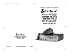
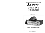
OPERATING INSTRUCTIONS FOR YOUR
40 CHANNEL
CITIZENS BAND
SSB/AM 2-WAY
MOBILE RADIO
Model 148 GTL
How To Use Your
40-CHANNEL,
CITIZENS BAND
SSB/AM 2-WAY MOBILE RADIO
Model 148 GTL
Contents
Page
The CB Story ....................................................................................1
Section I: Introduction......................................................................2
Section II: Specifications ..............................................................3, 4
Section III: Installation ........................................................5, 6, 7, 8
Section IV: Operation................................................................9 - 17
Controls and Indicators ....................................................................9
A.Control Functions ..............................................................9, 10, 11
B.Indicator Functions ......................................................................12
Operating Procedure to Receive......................................................12
Operating Procedure to Transmit ....................................................13
Receiving SSB Signals ..............................................................13, 14
Alternate Microphones and Installation ..............................15, 16, 17
Section V: Maintenance and Adjustment ..................................18 -21
FCC Warning ..................................................................................18
Section VI: Appendix ..........................................................19, 20, 21
Ten Code ........................................................................................19
A few Rules That Should Be Obeyed ..............................................20
How Your CB Can Serve You ..........................................................20
Use Channel 9 for Emergency Messages Only ................................21
Warranty Service Instructions ..........................................................22
Limited Two Year Warranty ..............................................................23
Cobra CB Radio Accessories ..................................Inside Back Cover
The CB Story
Section I Introduction
The Citizens Band lies between the shortwave broadcast and 10-meter Amateur
radio bands, and was established by law in 1949. The Class D two-way communications service was opened in 1959. (CB also includes a Class A citizens band and
Class C remote control frequencies.)
FCC regulations permit only “transmissions” (one party to another) rather than
“broadcasts” (to a wide audience). Thus, advertising is not allowed on CB Channels
because that is “broadcasting.”
FREQUENCY RANGE
The COBRA 148GTL transceiver represents one of the most advanced SSB/AM twoway radios ever designed for use as a Class D station in the Citizens Radio Service.
This unit features advanced Phase Lock Loop (PLL) circuitry, which is used in the AM
mode and in the upper and lower single sideband modes, providing complete cover
age of all 40 channels shown below.
NOTICE:
Replacement or substitution of transistors, regular diodes or
other parts of a unique nature, with parts other than those
recommended by Cobra, may cause violation of the technical regulations of Part 95 of the FCC Rules, or violation of
Type Acceptance requirements of Part 2 of the Rules.
Citizens Band (CB) Radio operators are no longer required to
obtain an FCC license to operate their CB equipment or
provide station identification.
An operator of a CB radio station is required to comply
with the communications act and with the rules of CB
Radio Operation.
Serial No.
Date of Purchase
Dealer Name
Channel
Channel
Channel Frequency
in MHz
Channel Frequency
in MHz
1
2
3
4
5
26.965
26.975
26.985
27.005
27.015
21
22
23
24
25
27.215
27.225
27.255
27.235
27.245
6
7
8
9
10
27.025
27.035
27.005
27.065
27.075
26
27
28
29
30
27.265
27.275
27.285
27.295
27.305
11
12
13
14
15
27.085
27.105
27.115
27.125
27.135
31
32
33
34
35
27.315
27.325
27.335
27.345
27.355
16
17
18
19
20
27.155
27.165
27.175
27.185
27.205
36
37
38
39
40
27.365
27.375
27.385
27.395
27.405
Keep this manual for detailed information about your Cobra CB radio.
SAVE YOUR SALES RECEIPT, THE CARTON AND “PACKING”
MATERIALS FOR POSSIBLE FUTURE USE.
The COBRA 148GTL has a vastly superior receiver which includes an RF gain control and noise blanker circuitry effective in both AM and SSB modes., and an automatic noise limiter effective in the AM mode. The receiver also features increased
protection against cross modulation and strong adjacent channel signals.
To obtain maximum performance please read carefully the descriptions and operating instructions in this manual.
1
2
Section II Specifications (Cont.)
Section II Specifications
GENERAL
Channels
Frequency Range
Frequency Control
Frequency Tolerance
Frequency Stability
Operating Temperature Range
Microphone
Input Voltage
Current Drain
Size
Weight
Antenna Conductor
Semiconductors
Meter (3-in-1)
40 AM, 40LSB, 40 USB.
26.965 to 27.405 MHz.
Phase Lock Loop (PLL) synthesizer.
0.005%
0.001%
-30° C to + 50° C
Plug-in dynamic; with push-to-talk
switch and coiled cord.
13.8V DC nominal, 15.9V max., 11.7V
min. (positive or negative ground).
Transmit: AM full mod., 2.2A. SSB 12
watts PEP output, 2A.
Receive: Squelched, 0.25A
Maximum audio output, 0.6A.
2 3/8”(H) x 7 7/8”(W) x 9 1/4”(D).
5 lbs.
UHF, S0239.
3 field effect transistors, 45 transistors,
63 diodes, 6 integrated circuits, 1 two
color light emitting diode.
Illuminated; indicates relative output
power, received signal strength,
and SWR.
TRANSMITTER
Power Output
Modulation
Intermodulation Distortion
SSB Carrier Suppression
Unwanted Sideband
Frequency Response
Output Impedance
Output Indicators
AM, 4 watts.
SSB, 12 watts, PEP.
High-and low-level Class B, Amplitude
Modulation.
SSB: 3rd order, more than -25 dB.
5th order, more than -35 dB.
55 dB.
50 dB.
AM and SSB; 300 to 2500 Hz.
50 ohms, unbalanced
Meter shows relative RF output power
and SWR. Transmit LED glows red when
transmitter is in operation.
3
RECEIVER
Sensitivity
SSB: 0.25 µV for 10dB (S+N)/N at greater
than 1/2-watt of audio output.
AM: 0.5 µV for 10 dB (S+N)/ at greater
than 1/2-watt of audio output.
Selectivity
AM: 6dB @ 3 KHz, 50 dB @ 9 KHz.
SSB: 6 dB @ 1.1 KHz, 60 dB @ 2.3 KHz.
Image Rejection
More than 65 dB.
IF Frequency
AM: 7.8 MHz 1st IF, 455 KHz 2nd IF.
SSB: 7.8 MHz.
Adjacent-Channel Rejection
60 dB AM & 70 dB SSB.
AM and SSB RF Gain Control
40 dB adjustable for optimum signal
reception.
Automatic Gain Control (AGC)
Less than 10 dB change in audio
output for inputs from 10 to 100,000
microvolts.
Squelch
Adjustable; threshold less than 0.25 µV.
ANL
Switchable.
Noise Blanker
RF type, effective on AM and SSB.
Voice Lock Range
±2.5 KHz.
Audio Output Power
4 watts into 8 ohms.
Frequency Response
300 to 2500 Hz.
Built-in Speaker
4 ohms, round.
External Speaker (Not Supplied)
8 ohms; disables internal speaker
when connected.
PA SYSTEM
Power Output
4 watts into external speaker.
External Speaker for PA (Not Supplied)
8 ohms.
(SPECIFICATIONS SUBJECT TO CHANGE WITHOUT NOTICE)
4
Section III Installation
Section III Installation (Continued)
LOCATION
IGNITION NOISE INTERFERENCE
Plan the location of the transceiver and microphone bracket before starting the installation. Select a location that is convenient for operation and does not interfere
with the driver or passengers in the vehicle. In automobiles, the transceiver is usually mounted below the dash panel, with the microphone bracket beside it.
Use of a mobile receiver at low signal levels is normally limited by the presence
of electrical noise. The primary source of noise in automobile installations is from
the generator and ignition system in the vehicle. Under most operating conditions,
when signal level is adequate, the background noise does not present a serious
problem. Also, when extremely low level signals are being received, the transceiver may be operated with vehicle engine turned off. The unit requires very little
current and therefore will not significantly discharge the vehicle battery.
Even though the COBRA 148GTL has ANL and NB controls, in some installations
ignition interference may be high enough to make good communications impossible. The electrical noise may come from several sources. Many possibilities exist
and variations between vehicles require different solutions to reduce the noise.
Consult your COBRA dealer or a 2-way radio technician for help in locating and
correcting the source of severe noise.
MOUNTING THE CONNECTION
The COBRA 148GTL is supplied with a universal mounting bracket. When mounting the bracket and radio to your car, make sure it is mechanically strong. Also
provide a good electrical connection to the chassis of the vehicle. Proceed as follows to mount the transceiver:
1. After you have determined the most convenient location in your vehicle, hold
the COBRA 148GTL with mounting bracket in the exact location desired. If
nothing will interfere with mounting it in the desired position, remove the
mounting bolts. Before drilling the holes, make sure nothing will interfere with
the installation of the mounting bolts.
2. Connect the antenna cable plug to the standard receptacle on the rear panel.
Most CB antennas are terminated with a type PL-259 plug and mate with the
receptacle.
3. Connect the red DC power input wire (with the fuse) to +13.8V DC. This wire
extends from the rear panel. In automobile installation, +13.8V DC is usually
obtained from the accessory contact on the ignition switch. This prevents the
set being left on accidentally when the driver leaves the car and also permits
operating the unit without the engine running. Locate the accessory contact on
most ignition switches by tracing the power wire from the AM broadcast receiver in the car.
4. Connect the black lead to -13.8V DC. This is usually the chassis of the car. Any
convenient location with good electrical contact (remove paint) may be used.
5. Mount the microphone bracket on either side of the transceiver, using the two
screws supplied. When mounting in an automobile, place the bracket under
the dash so the microphone is readily accessible.
5
ANTENNA
Since the maximum allowable power output of the transmitter is limited by the
FCC, the antenna is one important factor affecting transmission distance. Only a
properly matched antenna system will allow maximum power transfer from the 50
ohm transmission line to the radiating element. In mobile installations (cars,
trucks, boats, etc.), an antenna system that is non-directional should be used.
A vertically polarized, quarter-wavelength whip antenna provides the most reliable
operation and greatest range. Shorter, loaded-type whip antennas are more attractive, compact and adequate for applications where the maximum possible distance is not required. Also, the loaded whips do not present the problems of
height imposed by a full quarter-wavelength whip.
Mobile whip antennas utilize the metal body of the vehicle as a ground plane.
When mounted at a corner of the vehicle they are slightly directional, in the
direction of the body of the vehicle. For all practical purposes, however, the radiation pattern is nondirectional. The slight directional characteristic will be observed
only at extreme distances. A standard antenna connector (type SO239) is provided
on the transceiver for easy connection to a standard PL 259 cable termination.
If the transceiver is not mounted on a metal surface, it is necessary to run a separate ground wire from the unit to a good metal electrical ground in the vehicle.
When installed in a boat, the transceiver will not operate at maximum efficiency
without a ground plate, unless the vessel has a steel hull.
Before installing the transceiver in a boat, consult your dealer for information regarding an adequate grounding system and prevention of electrolysis between fittings in the hull and water.
6
Section III Installation (Continued)
TUNING THE ANTENNA FOR OPTIMUM SWR
Since there is such a wide variety of base and mobile antennas, this section will
strictly concern itself to the various types of mobile adjustable antennas.
Because antenna length is directly related to the channel frequency, it must be
tuned to resonate optimally all 40 channels of the transceiver. Channel 1 requires
a longer antenna than Channel 40 because it is a lower frequency.
Due to the various methods of adjusting antennas for proper SWR we have chosen
what we think is the optimum method:
A. Antennas with adjustable screws (set screws).
1. Start with the antenna extended and tighten the set screw lightly enough so
that the antenna can be lightly tapped with your finger for easy adjustment.
2. Set your COBRA 148GTL to Channel 21. Press the PTT (Push-to-Talk) switch,
and tap the antenna (making it shorter). The SWR meter will show a lower
reading each time the antenna is tapped. By continuing to shorten the antenna you will notice the SWR reading will reach a low point and then start rising again. This means that you have passed the optimum point for Channel
21. Extend the antenna a short distance and again follow the procedure
above.
When the lowest point has been reached, switch to Channel 1 and then to
Channel 40 and compare SWR readings. They should be almost equal.
B. Antennas which must be cut to proper length.
1. Follow the same procedure as above, but adjust the length by cutting in 1/8”
increments until a good match is obtained.
2. Be very careful not to cut too much at one time, as once it is cut, it can no
longer be lengthed.
3. The whip is easily cut by filing a notch all the way around and breaking the
piece off with a pliers.
Section III Installation (Continued)
D. Try a different location on your car (keeping in mind the radiation pattern
you wish).
E. Is the antenna perfectly vertical?
F. Try a different location in your neighborhood. Stay away from large metal
objects when adjusting (metal telephone or light posts, fences, etc.).
NOTE
The COBRA 148GTL will operate into an SWR of 2 to 1 indefinitely
and sustain an SWR of 20:1 for a maximum of 5 minutes at rated
operating conditions.
EXTERNAL SPEAKER
The external speaker jack (EXT. SPK.) on the rear panel is used for remote receiver
monitoring. The external speaker should have 8 ohms impedance and be able to
handle at least 4 watts. When the external speaker is plugged in, the internal
speaker is disconnected.
PUBLIC ADDRESS
To use the transceiver as a public address system connect an external 8 ohm
speaker (4 watts minimum) to the PA SPK. jack located on the rear panel. Direct
speaker away from the microphone to prevent acoustic feedback. Physical separation or isolation of the microphone and speaker is important when operating the
PA at high output levels.
NOTE
THE PROPER SETTING IS ACHIEVED WHEN THE SWR IS
1.5 OR BELOW, AND WHEN IT HAS THE SAME READING
FOR CHANNELS 1 AND 40.
If you are having difficulties in adjusting your antenna, check the following:
A. All doors must be closed when adjusting the antenna.
B. Make sure the antenna base is grounded.
C. Check your coaxial cable routing (it may be pinched when routed into the car).
7
8
Section IV Operation
CONTROLS AND INDICATORS
Section IV Operation (Continued)
4.
SWR CAL CONTROL (outer dual concentric). In order for you to achieve
maximum radiated power and the longest range, it is important that your
antenna be in good condition, properly adjusted and matched to your transceiver. The Built-in SWR (standing wave ratio) meter lets you easily measure
your antenna condition. To operate this function, connect your antenna to
the transceiver antenna output connector. Select a channel near the middle
of the band such as 21 or the channel you plan to use most frequently. Turn
the power on and set the meter function switch to the CAL position. Press
and hold the microphone push-to-talk button and using the SWR CAL control, adjust the meter to read the CAL position indicated on the meter face.
Then, without releasing the microphone button, switch the meter function
switch to the SWR position and read the SWR indicated. The lower the figure, the better, with 1 being ideal. Generally speaking, readings up to 3 are
acceptable, but over 3 indicates that you are losing radiated power and
antenna adjustment may be advisable.
5.
DYNAMIKE. Adjusts the microphone gain in the transmit and PA modes. This
controls the gain to the extent that full talk power is available several inches
away from the microphone. In the Public Address (PA) mode the control
functions as the volume control.
6.
VOICE LOCK. Allows variation of the receiver operating frequencies above
and below the assigned frequency. Although this control is intended primarily to tune in SSB signals, it may also be used to optimize AM signals as
described in the Operating Procedure paragraphs.
7.
DIM/NOR/BRT SWITCH. Controls the brightness of the meter and LED
channel indicator for optimum intensity for day or night-time driving.
8.
CHANNEL SELECTOR. This switch selects any one of the forty Citizens Band
channels desired. The selected channel appears on the LED readout directly
above the Channel Selector knob. Channel 9 has been reserved by the FCC
for emergency communications involving the immediate safety of life of individuals or immediate protection of property. Channel 9 may also be used to
render assistance to a motorist.
9.
0FF/ANL/NB + ANL SWITCH. In the ANL position only the automatic
noise limiter in the audio circuits is activated. When the switch is placed
in the ANL + NB position, the RF noise blanker also is activated. The
RF noise blanker is very effective for repetitive impulse noise such as
ignition interference.
There are thirteen controls and three indicators on the front panel of your COBRA
148GTL.
A. CONTROL FUNCTIONS
1. OFF/ON/VOLUME (inner dual concentric). Turn clockwise to apply power to
the unit and to set the desired listening level. During normal CB operation,
the VOLUME control is used to adjust the output level obtained either at the
transceiver speaker or the external speaker, if used.
2. SQUELCH (outer dual concentric). This control is used to cut off or eliminate
receiver background noise in the absence of an incoming signal. For maximum receiver sensitivity it is desired that the control be adjusted only to the
point where the receiver background noise or ambient background noise is
eliminated. Turn fully counterclockwise then slowly clockwise until the receiver noise disappears. Any signal to be received must now be slightly stronger
than the average received noise. Further clockwise rotation will increase the
threshold level which a signal must overcome in order to be heard. Only
strong signals will be heard at a maximum clockwise setting.
3. RF GAIN CONTROL (inner dual concentric). Used to reduce the gain of the
RF amplifier under strong signal conditions.
9
10
Section IV Operation (Continued)
Section IV Operation (Continued)
10. PA/CB SWITCH. Selects the mode of operation. In the CB position, the PA function is disabled and the unit will transmit and receive on the speaker that is connected. In the PA mode, incoming CB transmission will be heard through the PA
speaker. This allows you to monitor messages while outside of your vehicle.
To use the PA feature, a speaker having a voice coil impedance of 8 ohms and
a power handling capability of at least three watts should be used. This speaker
must be plugged into the PA SPKR jack at the rear of the transceiver. If the public address feature is to be used primarily for outdoor applications, the use of a
weatherproof horn type public address speaker is recommended. The durability
of this type speaker plus the inherent efficiency of such a speaker will provide
more than adequate results when combined with the high audio output level
available from the COBRA 148GTL. With the PA speaker connected as outlined previously, be sure that there is physical separation between the microphone and the speaker itself. If the speaker is located too close to the microphone, acoustic feedback will result when the public address system is operated at high volume. A directional type outdoor speaker reduces the amount of
isolation required. Some experimentation will determine the minimum amount
of isolation required for a given sound level from the public address system.
B. INDICATOR FUNCTIONS
1.
S-METER. Swings proportionally to the strength of the incoming signal.
2.
RF METER. Swings proportionally to the RF output power.
3.
SWR METER. Swings proportionally to the ratio of standing wave voltage and RF
output. Used to properly adjusts the length of the antenna, and to monitor the quality of the coaxial cable and all RF electrical connections. If there is any degradation
whatsoever in any of the above, due to humidity, salt, spray, vibration or corrosion,
the SWR meter reading will rise, thereby indicating that a problem exists.
To calibrate, switch to the “CAL” position, transmit in AM Mode by pressing the (PTT)
mic switch, and adjust the SWR control to the “CAL” mark on the meter then switch
to “SWR” position for the SWR measurement (Note: CB must be in AM mode).
4.
CHANNEL INDICATOR. Numbered LED indicates the selected channel you
wish to operate on.
5.
RECEIVE/TRANSMIT INDICATOR. The receiver/transmit LED indicator is
located next to the channel indicator. When in receive, the LED will be
green. When in transmit the LED will be red.
6.
PRESS-TO-TALK MICROPHONE. The receiver and transmitter are controlled
by the Press-To-Talk switch on the microphone. Press the switch and the
transmitter is activated, release the switch to receive. When transmitting, hold
the microphone two inches from the mouth and speak clearly in a normal
“voice”. The radio comes complete with low-impedance (500 ohm) dynamic
microphone. For installation instructions on the other microphones see
ALTERNATE MICROPHONES AND INSTALLATION section.
NOTE
PA volume is controlled by adjusting the DYNAMIKE knob to
the desired volume.
11. S-RF/CAL/SWR SWITCH. When in the S-RF position, the meter swings proportionally to the strength of the received signal. When transmitting, the meter indicates relative RF output power.
When in the “CAL” position, the SWR meter can be calibrated by adjusting the
“SWR” control to the “CAL” mark on the meter face.
When in “SWR” position, the standing wave ratio is measured.
12. MODE (LSB/AM/USB) SWITCH. This switch is used to select AM, LSB or USB
mode of operation. Unless the station with which communication is desired is
equipped with SSB, the AM mode is normally used. The mode selector switch
changes the mode of operation of both transmitter and receiver simultaneously.
Turn to “Receiving SSB signals” for a further explanation of single sideband.
13. TONE SWITCH-HI/NOR/LOW. This switch is used to shape the audio
response to the operator’s preference. Bass is increased in the LOW position
and treble is increased in the HI position.
11
OPERATING PROCEDURE TO RECEIVE
1.
Be sure that the power source, microphone and antenna are connected to the
proper connectors before going to the next step.
2.
Set PA-CB Switch to the CB position and turn unit on by turning VOL control
clockwise on COBRA 148GTL.
3.
Set the VOLUME for a comfortable listening level.
4.
Set MODE switch to the desired mode.
5.
Set the RF gain control fully clockwise for maximum RF gain.
6.
Listen to the background noise from the speaker. Turn the SQUELCH control
slowly clockwise until the noise JUST disappears (no signal should be present). Leave the control at this setting. The SQUELCH is now properly adjusted. The receiver will remain quiet until a signal is actually received. Do not
advance the control too far, or some of the weaker signals will not be heard.
7.
Set the CHANNEL selector switch to the desired channel.
8.
Adjust the VOICE LOCK control to clarify the SSB signals or to optimize
AM signals.
12
Section IV Operation (Continued)
OPERATING PROCEDURE TO TRANSMIT
1.
Select the desired channel of transmission.
2.
Set the DYNAMIKE control fully clockwise.
3.
If the channel is clear, depress the Push-To-Talk switch on the microphone
and speak in a normal voice.
RECEIVING SSB SIGNALS
There are three types of signals presently used for communications in the Citizens
Band: AM, USB, and LSB. When the MODE switch on your unit is placed in the
AM position, only standard double-sideband, full carrier signals will be detected.
An SSB signal may be recognized while in the AM mode by its characteristic
“Donald Duck” sound and the inability of the AM detector to produce an intelligible output. The USB and LSB modes will detect upper sideband and lower sideband respectively, and standard AM signals.
SSB reception differs from standard AM reception in that SSB receiver does not
require a carrier or opposite sideband to produce an intelligible signal. A singlesideband transmitted signal consists only of the upper or the lower sideband and
no carrier is transmitted. The elimination of the carrier from the AM signal helps to
eliminate the biggest cause of whistles and tones heard on channels which make
even moderately strong AM signals unreadable. Also, SSB takes only half of an AM
channel, therefore two SSB conversations will fit into each channel expanding the
40 AM channels to 80 SSB channels. The reduction in channel space required also
helps in the receiver because only half of the noise and interference can be
received with 100% of the SSB signal.
Section IV Operation (Continued)
Thus when a voice is used in place of a whistle or tone, in the proper listening
mode the voice will be received correctly whereas in the incorrect mode, the
voice will be translated backwards and cannot be made intelligible by the voice
lock control. When listening to an AM transmission, a correct sideband is heard
in either mode since both upper and lower sideband are received.
Once the desired SSB mode has been selected, frequency adjustment may be
necessary in order to make the incoming signal intelligible, the VOICE LOCK control allows the operator to vary frequency above and below the exact-center frequency of the received signal. If the sound of the incoming signal is high or low
pitched, adjust the operation of the VOICE LOCK. Consider it as performing the
same function as a phonograph speed control. When the speed is set too high,
voices will be high-pitched and if set too low, voices will be low-pitched. Also,
there is only one correct speed that will make a particular record produce the
same sound that was recorded. If the record is played on a turntable that rotates
in the wrong direction (opposite sideband) no amount of speed control (VOICE
LOCK) will produce an intelligible sound.
An AM signal received while listening in one of the SSB modes will produce a
steady tone (carrier) in addition to the intelligence, unless the SSB receiver is
tuned to exactly the same frequency by the VOICE LOCK control. For simplicity it
is recommended that the AM modes be used to listen to AM signals.
An SSB signal may be received only when the listening receiver is functioning in
the same mode. In other words, an upper sideband signal (USB) may be made
intelligible only if the receiver is functioning in the USB position.
If a lower sideband (LSB) signal is heard when the receiver is in the USB mode,
no amount of tuning will make the signal intelligible. The reason for this may be
understood if you consider that when the modulation is applied to the transmitter’s microphone in the USB mode, the transmitter’s output frequency is increased
whereas in the LSB mode the transmitter’s output frequency is decreased. The
result in listening to the receiver is that when the MODE switch is in the proper
position (either USB or LSB), a true reproduction of single tone of modulation will
result, and if the tone is increased in frequency (such as a low-pitched whistle or a
high-pitched whistle) you will hear the increase in the output tone of the receiver.
If the incorrect mode is selected, an increase in tone of a whistle applied to the
transmitter will cause a decrease in the resultant tone from the receiver.
13
14
Section IV Operation (Continued)
Section IV Operation (Continued)
ALTERNATE MICROPHONES AND INSTALLATION
For best results, the user should select a low-impedance dynamic type microphone
or a transistorized microphone. Transistorized type microphones have a low output
impedance characteristic. The microphones must be provided with a 4-lead cable.
The audio conductor and its shielded lead comprise two of the leads. The third
lead is for receive control, the forth is for transmit control.
The microphone should provide the functions shown in schematic below.
4 WIRE MIC CABLE
Pin Number
Mic Cable Lead
1
2
3
4
Grounding
Audio Lead
Transmit Control
Receive Control
Fig. 2. Microphone Cable Preparation
To wire the microphone cable to the plug provided, proceed as follows.
3
4
2
1
Fig. 1. Cobra 148GTL microphone schematic.
If the microphone to be used is provided with pre-cut leads, they must be revised
as follows.
1.
Cut leads so that they extend 7/16” beyond the plastic insulating jacket of the
microphone cable (see Fig. 2.)
2.
All leads should be cut to the same length. Strip the ends of each wire 1/8”
and tin the exposed wire.
Before beginning the actual wiring, read carefully, the circuit and wiring information provided with the microphone you select. Use the minimum head required in
soldering the connections. Keep the exposed wire lengths to a minimum to avoid
shorting when the microphone plug is reassembled.
15
Fig. 3. Microphone plug wiring.
1.
Remove the retaining screw.
2.
Unscrew the housing from the pin receptacle body.
3.
Loosen the two cable clamp retainer screws.
4.
Feed the microphone cable through the housing, knurled ring and washer as
shown Fig. 3B.
5.
The wires must now be soldered to the pins as indicated in the above wiring
tables. If a vise or clamping tool is available it should be used to hold the pin
receptacle body during the soldering operation, so that both hands are free to
perform the soldering. If a vise or clamping tool is not available, the pin receptacle body can be held in a stationary position by inserting it into the microphone jack on the front panel. The numbers of the pins of the microphone plug
are shown in Fig 4, as viewed from the back of the plug. Before soldering the
wire to the pins, pre-tin the wire receptacle of each pin of the plug.
16
Section IV Operation (Continued)
3
2
4
1
Fig. 4. Microphone plug pin numbers viewed from rear of pin receptacle.
Be sure that the housing and the knurled ring of Fig. 3 are pushed back onto the
microphone cable before starting to solder. If the washer is not captive to the pin
receptacle body, make sure that it is placed on the threaded portion of the pin
receptacle body before soldering.
If the microphone jack is used to hold the pin receptacle during soldering operation, best results are obtained when the connections to pins 1 and 3 are made first
and then the connections to pins 2 and 4. Use a minimum amount of solder and
be careful to prevent excessive solder accumulation on pins, which could cause a
short between the pin and the microphone plug housing.
6.
When all soldering connections to the pins of the microphone are complete,
push the knurled ring and the housing forward and screw the housing onto
the threaded portion of the pin receptacle body. Note the location of the
screw clearance hole in the plug housing with respect to the threaded hole
in the pin receptacle body. When the housing is completely threaded into
the pin receptacle body, a final fraction of a turn either clockwise or counterclockwise may be required to align the screw hole with the threaded hole
in the pin receptacle body. When these are aligned, the retaining screw is
then screwed into place to secure the housing to the pin receptacle body.
7.
The two cable clamp retainer screws should now be tightened to secure the
housing to the microphone cord. If the cutting directions have been carefully
followed, the cable clamp should secure to the insulation jacket of the microphone cable.
8.
Upon completion of the microphone plug wiring, connect and secure the
microphone plug in the transceiver.
17
Section V Maintenance and Adjustment
The COBRA 148GTL transceiver is specifically designed for the environment encountered in mobile installations. The use of all solid state circuitry and its light
weight result in high reliability. Should a failure occur, however, replace parts
only with identical parts. Do not substitute. Refer to the schematic diagram and
parts list.
NOTE
If the performance described in the OPERATION and MAINTENANCE
AND ADJUSTMENT sections is not obtained, review the operating instructions to insure that proper procedures were followed. If a problem still
exists, refer to WARRANTY SERVICE INSTRUCTIONS elsewhere in
this manual.
FCC WARNING
Replacement or substitution of transistors, regular diodes or other parts of
a unique nature, with parts other than those recommended by Cobra,
may cause violation of the technical regulations of Part 95 of the FCC
Rules, or violation of Type Acceptance requirements of Part 2 of the Rules.
Citizens Band (CB) Radio operators are no longer required to obtain an FCC
license to operate their CB equipment or provide station identification.
Nevertheless, an operator of a CB radio station is still required to comply
with the communications act and with the rules of CB Radio Operation.
18
Section VI Appendix (Continued)
Section VI Appendix
Citizens Band radio operators have largely adopted the “10-code” for standard
questions and answers. Its use permits faster communications and better understanding in noisy areas. The following table lists some of the more common codes
and their meanings.
10 CODE
Code
10-1
10-2
10-3
10-4
10-5
10-6
10-7
10-8
10-9
10-10
10-11
10-12
10-13
10-16
10-17
10-18
10-19
10-20
10-21
10-22
10-23
10-24
10-25
10-26
10-27
10-28
10-29
10-30
10-32
10-33
10-34
10-35
10-36
Meaning
Receiving poorly
Receiving well
Stop transmitting
OK, message received
Relay message
Busy, stand by
Out of service, leaving air
In service, subject to call
Repeat message
Transmission completed,
standing by
Talking too rapidly
Visitors present
Advise Weather/Road conditions
Make pick up at
Urgent business
Anything for us?
Nothing for you, return to base
My location is
Call by telephone
Report in person to
Stand by
Completed last assignment
Can you contact
Disregard last information
I am moving to channel
Identify your station
Time is up for contact
Does not conform to FCC rules
I will give you a radio check
EMERGENCY TRAFFIC
Trouble at this station
Confidential information
Correct time is
19
Code Meaning
10-37 Wrecker needed at
10-38 Ambulance needed at
10-39 Your message delivered
10-41 Please turn to channel
10-42 Traffic accident at
10-43 Traffic Tie up at
10-44 I have a message for you
10-45 All units within range
please report
10-50 Break channel
10-60 What is the next message
number?
10-62 Unable to copy, use
phone
10-63 Net directed to
10-64 Net clear
10-65 Awaiting your next
message/assignment
10-67 All units copy
10-70 Fire at
10-71 Proceed with transmission
in sequence
10-77 Negative contact
10-81 Reserve hotel room for
10-82 Reserve room for
10-84 My telephone number is
10-85 My address is
10-91 Talk closer to mike
10-93 Check my frequency on
this channel
10-94 Please give me a long
count
10-99 Mission completed, all
units secure
10-200 Police needed at
A FEW RULES THAT SHOULD BE OBEYED
1.
You are not allowed to carry on a conversation with another station for more
than five minutes at a time without taking a one-minute break, to give others
a chance to use the channel.
2.
You are not allowed to blast others off the air by over-powering them with
illegally amplified transmitter power, or illegally high antennas.
3.
You can’t use the CB to promote illegal activities.
4.
You are not allowed to use profanity.
5.
You may not play music in your CB.
6.
You may not use your CB to sell merchandise or professional service.
HOW YOUR CB CAN SERVE YOU
•
•
•
•
•
•
•
•
•
Warn of traffic tie ups ahead.
Provide weather and road information.
Provide help fast in event of emergency or breakdown.
Suggest good spots to eat and sleep.
Make long trips more interesting, and help keep you awake.
Provide direct contact with your office or home.
Make friends for you as you travel.
Provide “local information” to find your destination.
Help law enforcement officers by reporting drunk and reckless drivers.
20
Section VI Appendix (Continued)
USE CHANNEL 9 FOR EMERGENCY MESSAGES ONLY
FCC gives the following examples of permitted and prohibited types of communications for use on Channel 9. These are guidelines and are not intended to be allinclusive.
Permitted
Example Message
Yes
”A tornado sighted six miles north of town.”
No
”This is observation post number 10. No tornado sighted.”
Yes
”I am out of gas on Interstate 95.”
No
”I am out of gas in my driveway.”
Yes
There is a four-car collision at Exit 10 on the Beltway, send
police and ambulance.”
No
”Traffic is moving smoothly on the Beltway.”
Yes
”Base to Unit 1, the Weather Bureau has just issued a thunder storm warning. Bring the sailboat into port.”
No
”Attention all motorists. The Weather Bureau advises that the
snow tomorrow will accumulate 4 to 6 inches.”
Yes
“There is a fire in the building on the corner of 6th and
Main Streets.”
No
“This is Halloween patrol unit number 3. Everything is
quiet here.“
If You Need Service
If You Think You Need Service, Call 773-889-3087
You may be asked to send your unit to the Cobra factory. It will be necessary to
furnish the following, in order to have the product serviced and returned.
1. For Warranty Repair, include some form of proof-of-purchase, such as a mechanical reproduction or carbon or a sales receipt. If you send the original
receipt it cannot be returned.
2. Send the entire product. Must include CB unit and microphone.
3. Enclose a description of what is happening with the unit. Include a typed or
clearly printed name and address of where the unit is to be returned.
4. Pack unit securely to prevent damage in transit. If possible, use the original packing material.
5. Ship prepaid and insured by way of a traceable carrier (to avoid loss in transit)
such as United Parcel Service (UPS), Roadway Parcel Service (RPS) or First Class
Insured Mail to Cobra Factory Service, Cobra Electronics Corporation, 6500 W.
Cortland St., Chicago, IL 60707. Cobra is not responsible for units not received if
package has not been properly insured.
6. If the unit is in warranty, upon receipt of your unit it will either be repaired or
exchanged depending on the model. Please allow approximately 3 to 4 weeks
before contacting us for status. If the unit is out of warranty a letter will automatically be sent informing you of the repair charge or replacement charge. If
you have any questions, please call 773-889-3087 for assistance.
For technical assistance, please call our Automated Help Desk
which can assist you by answering the most frequently asked
questions about Cobra products.
(773) 889-3087
24 hours a day, 7 days a week.
A Consumer Service Representative can be
reached through this number
8:00 am - 8:00 pm, Monday through Friday, CST.
E-mail questions to “[email protected]”
21
22
COBRA CB RADIO ACCESSORIES
LIMITED TWO YEAR WARRANTY
COBRA ELECTRONICS CORPORATION warrants that its COBRA CB Radios, and
the component parts thereof, will be free of defects in workmanship and materials
for period of two (2) years from the date of first consumer purchase. This warranty
may be enforced by the first consumer purchaser, provided that the product is utilized within the U.S.A.
COBRA will, without charge, repair or replace, at its option, defective CB radios,
products or component parts upon delivery to the COBRA factory Service
Department, accompanied by proof of the date of first consumer purchase, such as
a duplicated copy of a sales receipt.
You must pay any initial shipping charges required to ship the product for warranty
service, but the return charges will be at Cobra's expense, if the product is repaired
or replaced under warranty. For further details concerning procedures for obtaining
service, see the “If You Think You Need Service” section of the Owner’s Manual.
Exclusions: This limited warranty does not apply; 1) to any product damaged by
accident; 2) in the event of misuse or abuse of the product or as a result of unauthorized alterations or repairs; 3) if the serial number has been altered, defaced or removed; 4) if the owner of the product resides outside the U.S.A.
All implied warranties, including warranties of merchantability and fitness for a
particular purpose are limited in duration to the length of this warranty.
COBRA shall not be liable for any incidental, consequential or other damages; including, without limitation, damages resulting from loss of use or cost of
installation.
Some states do not allow limitations on how long an implied warranty lasts and/or
do not allow the exclusion or limitation of incidental or consequential damages, so
the above limitations may not apply to you.
COBRA ELECTRONICS CORPORATION
6500 W. Cortland Street
Chicago, Illinois 60707
Description
Part No.
Cost Ea. X Qty. = Amount
Replacement microphone with 4-pin connector
for 148 GTL
CA-73
$19.95
MOBILE POWER MICROPHONE
Amplified Power Microphone with 4-pin connector
for 148 GTL
CA-75
$19.95
NOISE CANCEL MICROPHONE for 148 GTL
CA-77
$39.95
ECHO POWER MICROPHONE or 148 GTL
CA-79
$69.95
High Performance, Magnetic Mount Antenna.
Spring Base, Tunable and 1,000 watt Capacity
ATW-400
$39.95
DC POWER CORD Exact replacement power cord
for 148GTL
426-011-N-001
$7.50
MOUNTING BRACKET Replacement for 148GTL
250-044-N-001
$4.50
MOUNTING BRACKET SCREWS
for 148GTL
634-188-9-001
$.25 ea.
★★
Illinois residents add 8.75%
Amount
(Tax if applicable )
★★
Indiana residents add 5%
★★ Michigan residents add 6 %
Shipping//handling
$3.50
Total
★★
Ohio residents add 5%
★★ Wisconsin residents add 5%
If you wish, you can order directly from Cobra
Order by phone:
Call 1-773-889-3087 (Press 1 from the main menu) 8a.m.-8p.m. M-F CST.
Order by mail or fax: Please fill out order form below, and mail/fax
directly to Cobra.
Mail to:
Cobra Accessories Dept.
6500 W. Cortland St., Chicago, IL 60707
Fax to:
1-773-622-2269
Please print clearly:
Name
Address (Not P.O. Box)
City
State
Credit Card No.
Zip
Exp. Date
Customer Signature
Circle One:
23
Visa
MasterCard
Discover
Allow 4 to 6 weeks for delivery. Offer valid in Continental U.S. only.
2
Cobra Electronics Corporation
6500 W. Cortland Street
Chicago, IL 60707
PRINTED IN THAILAND
001
©COBRA ELECTRONICS CORPORATION 1996
480-163-P-