1
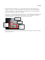
111 Canfield Avenue • Randolph, New Jersey 07869 • 1-800-LANDICE •
FAX 973-927-0630
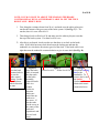
ELLIPTIMILL E8/E9
HOME & COMMERCIAL
SERVICE MANUAL
Version 3.2
For Technical Service Call 1-(800)-LANDICE
PAGE 2
Service Manual Version
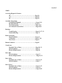
Pages 2………….... ………Table of Contents.
SECTION 1 – INTRODUCTION AND WTY INFORMATION.
Pages 3………………………How to use this manual.
Pages 4-8..……………………Replica WTY Cards & Policies.
Page 9………………………Service Authorization Claim Form.
SECTION 2 - INSTALLATION
Page 10……………………….Tools needed for repair.
Pages 11-13...............................Safety Instructions.
Page 14……………………….Electrical Requirements for E-Series Elliptimill.
Page 15-21……………………Assembly Instructions.
Page 22………………………..E-Series DCP Assembly Instructions.
Pages 23-25…………………...E-Series LVS2 Assembly Instructions.
SECTION 3 – PARTS IDENTIFICATION
Page 26………………………..E-Series Elliptimill Dimensions & Weight
Pages 27-33……………………E-Series Parts List w/ Exploded View.
Pages 34-35……………………E-Series Control Panels and Features.
Page 36………………………..Accessing Diagnostic Features on Elliptimill Consoles.
Pages 37-39……………………Definition of Parts.
SECTION 4 – SERVICING LANDICE ELLIPTICALS
Page 40.......................................Diagnosing an Elliptimill “Knock”.
Pages 41-42…………………….Isolating Noises.
Pages 43-49…………………….Testing Components.
Pages 50-55…………………….Removal/Replacement of Components.
Page 56………………………..LED Configuration for Relay Board.
Pages 57-58…………………….Brake Controller Calibration.
Pages 59-61…………………….Diagnostic Flow Charts.
Page 62………………………..Elliptimill Wiring Schematic.
Page 63………………………..Elliptimill Main Wiring Harness.
Page 64………………………..LVS2 Breakdown for Elliptimill.
Page 65-66…………………….LVS2 Retrofit Instructions.
Page 67-68…………………….Index
PAGE 3
How to Use this Manual
This manual is designed to help service technicians in the installation, maintenance, or repair of
Landice E8 and E9 model elliptimill’s. It covers terminology, installation, tools needed,
diagnostics, removal and replacement of parts, warranty forms, Service Authorization forms,
wiring schematics, and recommended maintenance. We are including an Index to further aid
you in quickly finding what you need.
If you find a problem not covered in this manual please call 1-800-LANDICE to talk to a
Landice Service Technician.
PAGE 4
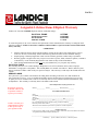
Assignable Lifetime Home Elliptical Warranty
Landice, Inc. warrants all HOME ellipticals sold into residential settings:
ELLIPTICAL FRAME
ELLIPTICAL PARTS
WEAR ITEMS
SERVICE LABOR
LIFETIME
LIFETIME
LIFETIME
1 YEAR
To ensure the quality of our service and meet the requirements of this commitment, this warranty is contingent on the
following conditions. Failure to meet these conditions without Landice’s expressed written consent shall void the
factory warranty.
CONDITIONS
•
All home ellipticals must be dealer-installed within a 60-mile driving radius of the selling dealer’s nearest
retail store. In cases of uncertainty, Internet-based driving directions will be used to determine mileage.
• Prepaid postage “Warranty Registration Card” must be mailed by purchaser within 30 days of purchase.
• Warranty applies to original owner only except in cases where a spouse, child, or domestic partner, is named as
a “Beneficiary” on the “Warranty Registration Card” within 30 days of initial installation.
• Floor models and demonstration units over one-year old shall carry a 5-year parts only warranty.
ELLIPTICAL PARTS
This warranty does not cover cosmetic damage, damage due to acts of God, accident, misuse, abuse, improper
maintenance, or negligence to the product. This warranty does cover normal wear and tear. Worn or defective parts
must be returned to Landice within 30 days of repair for analysis. This warranty is valid only in the United States and
Canada.
SERVICE LABOR
For a period of 1 year, Landice will reimburse the selling dealer according to the terms, rates and conditions in
effect at the time of service. A service authorization number must be obtained prior to performing service in order
to qualify for service reimbursement. This service warranty does not cover customer instruction, installation, setup,
or adjustments. This warranty is valid only in the United States and Canada.
Home Elliptical Warranty Registration Card
Registration card must
be mailed within 30 days
of purchase in order to
register your warranty.
Landice will send you a
complimentary Landice
T-Shirt upon receipt of
your registration card.
Model #_____________ Serial #______________ Date Purchased _________
CUSTOMER INFORMATION
Name____________________________________________________________
Occupation_______________________________________________________
Address__________________________________________________________
City & State______________________________________ZIP______________
Phone___________________________Fax _____________________________
Do you understand the owner's manual & safety precautions outlined?________
How did you hear about Landice? ____________________________________
What factors most influenced your decision to purchase a Landice elliptical?
_________________________________________________________________
FITNESS LEGACY
In the event of my death, I hereby transfer my rights as stated in the terms and conditions of Landice’s
“Assignable Lifetime Home Elliptical Warranty” to:
__________________________________________________________________
Beneficiary: Spouse, Children (list names), or Domestic partner
PAGE 5
5-Year Club Elliptical Warranty
Effective January 1, 2008, Landice warrants all CLUB series ellipticals as follows:
ELLIPTICAL PARTS:
5-YEARS
All defective parts must be delivered prepaid to Landice where they will be replaced for a period of 5-years. This
warranty does not cover cosmetic damage, damage due to acts of God, accident, misuse, abuse, or negligence to the
product. This warranty is valid only in the United States and Canada.
SERVICE LABOR:
1-YEAR
For a period of 1-year, the selling dealer will be reimbursed by Landice according to the terms, rates, and conditions
in effect at the time of service. A service authorization number must be obtained by an authorized dealer prior to
performing service in order to qualify for service reimbursement. This service warranty does not cover customer
instruction, installation, setup, or adjustments. This warranty is valid only in the United States and Canada.
Registration card must
be mailed within 30 days
of purchase in order to
register your warranty.
5-Year Club Elliptical Warranty Registration Card
Model #_____________ Serial #______________ Date Purchased _________
CUSTOMER INFORMATION
Landice will send you a
complimentary Landice
T-Shirt upon receipt of
your registration card.
Facility___________________________________________________________
Contact__________________________________________________________
Address__________________________________________________________
City & State______________________________________ZIP______________
Phone___________________________Fax _____________________________
Do you understand the owner's manual & safety precautions outlined?________
How did you learn about Landice? ____________________________________
What factors most influenced your decision to purchase a Landice elliptical?
_____________________________________________________
____________
DEALER INFORMATION
Dealer Name______________________________________________________
City & State_____________________________ Price Paid_________________
Dealer Comments__________________________________________________
PAGE 6
LANDICE WARRANTY AND
POLICIES
The Service Warranty covers installation of parts shown to be defective in
material or workmanship. The selling dealer is responsible for labor for treadmills
needing repairs. A Service Authorization (SA) number must accompany any service
reimbursement request. Service Authorization numbers are given when the selling dealer
or the service technician calls Landice prior to beginning work on the treadmill. This
allows Landice to verify that the elliptical is within the labor warranty and also aids us in
helping the technician troubleshoot the elliptical. Landice welcomes technicians to call us
from the field and gives these calls the highest priority.
This Service Warranty does not cover customer instruction, installation, setup,
maintenance, or adjustments to the drivebelt. Line Cords (power cords) are also not
covered by this warranty as these can only be damaged by misuse or abuse.
This warranty does not cover cosmetic damage, damage due to acts of God,
accident, misuse, abuse, or negligence of the product.
The part will be covered in full
only if it exhibits evidence of a manufacturing or material defect during the warranty
period. Please keep in mind, “negligence of the product” includes damage inflicted by
using the elliptical in an improper fashion.
PAGE 7
SERVICE REIMBURSEMENT POLICY:
This is offered to all Landice dealers as well as all authorized Landice service
providers. Landice covers our ellipticals with a 1-year labor reimbursement policy. That
means we will pay to fix our ellipticals as long as it’s within one year from the date the
treadmil was purchased.
OUR POLICY:
Landice will reimburse the selling dealer according to our labor rate schedule. If
you are a service provider for Landice and do not sell our product, you have the option of
billing us direct or you can bill the dealer that you’re providing service for. Generally, if
our capped rate does not cover your labor charge you would bill the selling dealer. The
current rate is $30.00 per hour and is capped at a maximum of one hour labor and one
hour travel per elliptical failure. Diagnostic and return trips are not covered. If parts
were credited out or Invoice was partially paid the claim will be denied. Note that set-up
procedures are not covered by this warranty.
Set-Up Includes: Assembly, replacing parts due to cosmetic damage or abuse, and
performing any additional adjustments that may have been upset during shipping.
The dealer must call for a service authorization number prior to performing any
service to verify the elliptical is under labor warranty. It is advisable to call Landice from
the elliptical location to successfully diagnose the problem. This will insure that the
correct part will be shipped out the first time. Labor claim forms must be submitted
within three months from the date service was performed. Labor claim forms must be
completely filled out and have the Landice Service Authorization number at the top.
Generally service claims are paid out upon the return of defective parts and/or crediting
of the warranty invoice. If parts are outstanding for a period of more than 90 days
previously submitted service claims will be returned unpaid.
FLOOR MODELS AND DEALERS STOCK:
If the dealer sells an elliptical to a customer within one year of its purchase from Landice,
the warranty period will be extended to start from the date of sale to the customer. If a
home ellipticall is over 1 year old when sold to a customer, the elliptical will carry a 5
year parts warranty and there will be NO labor warranty. If a commercial unit is over 1
PAGE 8
year old when sold to a customer, the elliptical will carry the remainder of the parts
warranty from the date of shipment with NO labor warranty.
PARTS POLICY
Our policy requires that all defective parts be returned to Landice. All warranty parts will
be billed to the dealer at dealer cost. Landice will credit this invoice upon receipt of
defective parts. It is the dealer's responsibility to return the defective parts to Landice
with a copy of the invoice or packing slip. If the defective parts are not returned within
30 days, payment of invoice is expected in full.
WARRANTY PART ORDERING:
When ordering parts under warranty please have the following information available.
Warranty orders can not be processed without this information:
1) Customer's name, address and phone number
2) Elliptical serial number
3) Detailed description of failure
PURCHASE PART ORDERING:
Serial numbers are recommended to help ensure the correct part is shipped. Purchased
parts are covered by a 90 day replacement part warranty from the date the order shipped.
PAGE 9
111 Canfield Avenue • Randolph, New Jersey 07869 • 1-800-LANDICE • FAX 973-927-0630
SERVICE CLAIM FORM
SA#
DEALER INFORMATION:
Service Dealer / Dealer Name:
Address
City
Phone(
Contact
State
Zip
State
Contact
Zip
)
CUSTOMER INFORMATION
Name
Address
City
Phone(
)
TREADMILL INFORMATION
Model Type:
Frame Serial #
DCP Serial # (if applicable)
Out of box problem
Yes
Date of Service
Date of Purchase
No
CUSTOMER COMPLAINT
SERVICES PERFORMED/PARTS REPLACED
TRAVEL / LABOR: Travel Time:
Labor Time:
VALIDATION SIGNATURES
Service Rep. Signature
TOTAL TIME: _________
Date
Customer Signature
IN ORDER TO PROCESS THIS CLAIM IN THE LEAST AMOUNT OF TIME,
SEND THE SERVICE CLAIM WITH THE DEFECTIVE WARRANTY PART.
DO NOT SUBMIT SERVICE CLAIMS WITHOUT SERVICE AUTHORIZATION NUMBERS.
PAGE 10
RECOMMENDED TOOLS FOR SERVICING LANDICE
ELLLIPTIMILLS
1. 10-17mm Allen Key socket or wrench set
2. 10-17mm Wrenches.
3. Ratchet & Extension.
4. Vice Grips.
5. #1, 2, or 3 Phillips Head Screwdriver or power bits.
6. #1, 2, or 3 Flat Head Screwdriver or power bits.
7. Cordless or Corded Drill.
8. Rubber Mallet.
9. Diagonal cutters/Dykes
10. Wire Stripper.
11. Wire Cutters.
12. Digital multimeter (Analog meters are not recommened).
PAGE 11
IMPORTANT OPERATING SAFETY INSTRUCTIONS
WARNING:
Failure to observe the following operating instructions can result
in serious injury!
[1]
If you are suffering from any illness, condition, or disability which affects your
ability to run, walk or exercise, do not use this product without consulting your
doctor first.
[2]
If you are suffering from any illness, condition, or disability which affects your
ability to run, walk or exercise, do not use this product without supervision present.
Failure to do so can result in serious injury should you fall while the machine is in
motion..
[3]
Failure to leave ample clearance around the elliptical could result in the user
becoming trapped between the mechanism and a wall, resulting in serious injury.
Allow a minimum clearance of 6 inches on each side of the elliptical.
Allow a minimum clearance of 1 foot at the rear of the elliptical.
[4]
Be sure to familiarize yourself with the owner manual. Look it over carefully. Be
sure you understand the control panel operation before using the elliptical.
When using an electrical appliance, basic precautions should always be followed.
Read all instructions before using.
DANGER: Always unplug the elliptical before cleaning or removing any shrouds.
To reduce the risk of electrical shock in the event of an electrical storm, always
unplug the elliptical from the electrical outlet after using.
PAGE 12
IMPORTANT OPERATING SAFETY INSTRUCTIONS
WARNING: To reduce the risk of electrical shock or injuries to persons:
[1]
An appliance should never be left unattended when plugged in. Unplug from
outlet when not in use.
[2]
Close supervision is necessary when this unit is used by or near children or
disabled persons.
[3]
Use this elliptical only for its intended use as described in this manual.
[4]
Never operate this elliptical if it has a damaged cord or plug, if it is not working
properly, or if it has been damaged. Call your selling dealer immediately for
examination and repair.
[5]
Keep the power cord away from heated surfaces. Be sure the line cord has plenty
of slack and does not get pinched underneath the elliptical.
[6]
Never drop or insert any object into any opening. Be sure no objects are near or
underneath the elliptical
[7]
Do not operate where aerosol (spray) products are being used or where oxygen is
being administered.
[8]
Connect this appliance to a properly grounded dedicated outlet only.
[9]
To disconnect, press the OFF button, and unplug the unit from the wall outlet.
GROUNDING INSTRUCTIONS
This product must be grounded. If it should malfunction or break down, grounding
provides a path of least resistance for electric current to reduce risk of electrical shock.
This product is equipped with a cord having an equipment grounding conductor and
a grounding plug. The plug must be plugged into an outlet that is properly installed
and grounded in accordance with all local codes and ordinances.
120 VOLT ELLIPTIMILLS
Ellipticals marked 120 VAC are intended for use in a nominal 120-volt circuit with a
grounding plug. Make sure the product is connected to an outlet having the same
configuration as the plug. No adapter should be used with this product.
PAGE 13
200 – 250 VOLT ELLIPTIMILLS
Ellipticals marked 200 – 250 VAC are intended for use on a circuit having a nominal
rating more than 120V and are factory-equipped with a specific cord and plug to permit
connection to a proper electric circuit. Make sure the product is connected to an outlet
having the same configuration as the plug. No adapter should be used with this product.
If the product must be reconnected for use on a different type of electric circuit, qualified
service personnel should make the reconnection.
DANGER: Improper connection of the equipment-grounding connector can result
in a risk of electric shock. Check with a qualified electrician or serviceman if you
are in doubt as to whether the product is properly grounded. Do not modify the
plug provided with the product. If it will not fit in the outlet, have a proper outlet
installed by a qualified electrician.
PAGE 14
ELECTRICAL REQUIREMENTS FOR E-SERIES
ELLIPTIMILL
All Ellipticals are automatically rated for 110 or 220 VAC with no external transformer.
The power supply will know what voltage it’s receiving and will bring it to a 12Vdc
supply to power the upper console.
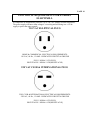
110 VAC ELLIPTICAL PLUG
HOME & COMMERCIAL ELECTRICAL REQUIREMENTS:
110 VAC, 60 Hz , 15 AMP - DEDICATED CIRCUIT & GROUND
PLUG - NEMA 5-15P (PLUG)
RECEPTACLE - NEMA 5-15R (RECEPTACLE)
220 VAC CLUB & INTERNATIONAL PLUG
220V CLUB & INTERNATIONAL ELECTRICAL REQUIREMENTS:
220VAC , 60 Hz , 15 AMP - DEDICATED CIRCUIT & GROUND
PLUG - NEMA 6-15P (PLUG)
RECEPTACLE - NEMA 6-15R (RECEPTACLE)
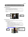
PAGE 15
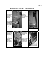
ASSEMBLY INSTRUCTIONS
1. Cut the
strapping and lift
the box top and put
it to the side to be
used as a remote
work station.
2. Use the box top
as a work station to
lay out all of the
components.
Open up the main
hardware bag so
that you can clearly
see all the
numbered
hardware bags.
NOTE: Hardware
bag "STEP 6" is
intentionally not
included. This
hardware comes
preinstalled from
the factory.
3. Remove upright
and place it on top
of the big white
foam packaging
cube.
4. Remove the
rest of the
components and
place them on the
box top or near by.
Remove the base
frame from the
pallet and place it
in the exact spot
you plan to use it.
Tip: Keep the cross brace
foam tubes on until you install
upright to avoid accidental
scratching.
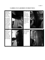
PAGE 16
5. Check that all
the leveling feet (6)
are turned all the
way up into the
frame by tilting the
machine and
adjusting them as
shown. Attempt to
rock the unit back
and forth to check
for stability. If
unstable, adjust
the feet until it
stabilizes.
6. Slide the
vertical stride
adjustment
members into the
upright housing.
DO NOT REMOVE
the plastic wrap /
foam that secures
the two arms
together. NOTE:
There is a
difference between
right and left ("L" /
"R" decals).
7. Open hardware
bag "STEP 1".
Use the big flat
washer, lock
washer and bolt to
fasten the vertical
stride adjustment
members. After
firmly tightening,
cap the tubes with
the large black
dome finish plugs
to conceal the
hardware.
8. Place the
protective
cardboard over the
frame as shown in
the picture.
Note: Save the remaining black
screws in hardware bag “STEP
1”. You will need them after
mounting the upright “STEP 12”.
Tip: Remove the bearing caps
afterwards to avoid accidental
upright scratching.
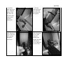
PAGE 17
9. Pick up the
upright assembly
and walk it into the
frame from the rear
in as shown in the
picture.
10. Carefully
rotate the upright
legs into the
correct alignment
and slip them into
their respective
black fittings on top
of the frame. Once
in, you can remove
the protective
cardboard and the
plastic wrap / foam
that secures the
arms together
(arrow pointing to it
in picture).
11. Open
hardware bag
"STEP 2".
Commence, but do
not tighten all the
screws with
washers on each
upright using the
smaller allen key
(12 per side). You
will tighten them
later.
12. Using the rest
of the screws in the
the hardware bag
"STEP 1", discard
the protection caps
and firmly fasten
the moving hand
rails using the
bigger allen key.
NOTE: There is a
difference between
right and left ("L" /
"R" decals).
PAGE 18
13. Open
hardware bag
"STEP 3".
Connect the crank
arm to the crank.
Tighten the top two
bolts first, then the
bottom two. DO
NOT REMOVE the
plastic film. It is an
isolation dampener
that alleviates
mechanical stress
between joints.
14. Open
hardware bag
"STEP 4".
Connect the pedal
arm to the vertical
member. Slide the
bolt in from the
outside and tighten
the nut very firmly.
NOTE: There is a
difference between
right and left
pedals ("L" / "R"
decals).
15. Use the black
screws in the
hardware bag
"STEP 4". Push
the pedals forward
and screw on the
inside plastic joint
covers. TIP: You
must hold the
pedal in the
forward position
in order to get a
screw driver in a
usable position.
16. Use the
remaining black
screws in the
hardware bag
"STEP 4". Fasten
the outside plastic
joint covers.
PAGE 19
17. Slide the
handrails into the
upright fittings.
Open hardware
bag "STEP 5" and
use the smaller
allen key to
commence the (2)
screws on each
rail. NOTE: There
is a difference
between right and
left rails ("L" / "R"
decals).
18. Use the
remaining bolts in
hardware bag
"STEP 5" to fasten
the bottom of the
rail. Once you
tighten these, finish
tightening the
smaller screws at
the top of the rail.
Once rails are
tight, finish
tightening the
upright screws
from assembly
"Step 12" and the
handrail screws
from the previous
step.
19. Open
hardware bag
"STEP 7". Use the
screws that have a
sharp point at the
end to fasten the
plastic bed
endcaps. Each
endcap used (4)
screws.
20. Feed the
upright harness
(found in
membrane box)
down the leg.
Slide it all the way
down until you can
grab it at the base
of the machine
through the access
hole. TIP: Once
you grab the
harness at the
base, make sure to
clip in the harness
at the top of the
upright to prevent it
from falling down
inadvertently.
Tip: If you
have
trouble with
alignment,
use a long
screwdriver as a
lever at the
base of the
rail to help
get the first
bolt in.
13mm
PAGE 20
21. Clip the
harness to the (2)
harness clips along
the frame. Once
you have secured
the harness to the
clips, connect it to
the female
connector on the
lower electronic
board. TIP: If
installing an LVS,
install the Caddy
(reading rack)
now. Then LVS,
then resume this
assembly (step
22).
22. Mount the
front cover. Use
the remaining
screws in hardware
bag "STEP 7" to
mount the cover.
NOTE: Use the
machine screws
(4) in the bag with
a dull point to
fasten the cover to
the frame (shown
in picture). Use
the remaining
sharp point screws
(8) to mount the
rest of the cover to
the silver side
covers.
23. Place the
membrane in the
control panel and
connect the two
harnesses coming
from the contact
hand grips to the
smaller board
located on the far
side of the
membrane. The
white connectors
can go on either of
the two available 3pin connectors.
24. Connect the
upper harness to
the upper board.
Center the
membrane and
pitch it back into
place so that the
velcro mates
securely. Connect
the main power
cord to the front
cover so you can
turn the machine
and verify all
electrical
connections.
PAGE 21
25. Open
hardware bag
"STEP 9" and use
the screws to
attach the upright
endcaps to the
upright.
26. Open
hardware bag
"STEP 8" and use
the allen key to
fasten the rear step
of the elliptical.
27. Check to make
sure that the
leveling feet below
the step are firmly
touching the
ground to prevent
any rocking.
28. Move on to the
Caddy (reading
rack) installation.
The instructions
are located in the
box with the caddy.
NOTE: The main
4 mounting bolts
for the Caddy are
not 7/16", use
10mm.
IMPORTANT: VERIFY THAT ALL
SCREWS ARE TIGHT OR KNOCKING
NOISE MAY OCCUR.
PAGE 22
E-SERIES DCP ASSEMBLY INSTRUCTIONS
1. Feed the
upright harness
(found in
membrane box)
down the leg.
Slide it all the way
down until you
can grab it at the
base of the
machine through
the access hole.
TIP: Once you
grab the harness
at the base, make
sure to clip in the
harness at the top
of the upright to
prevent it from
falling down
inadvertently.
2. Clip the
harness to the (2)
harness clips
along the frame.
Once you have
secured the
harness to the
clips, connect it to
the female
connector on the
lower electronic
board.
3. Place the
membrane in the
control panel and
connect the two
harnesses coming
from the contact
hand grips to the
smaller board
located on the far
side of the
membrane. The
white connectors
can go on either of
the two available
3-pin connectors.
4. Connect the
upper harness to
the upper board.
Center the
membrane and
pitch it back into
place so that the
velcro mates
securely. Connect
the main power
cord to the front
cover so you can
turn the machine
and verify all
electrical
connections.
PAGE 23
E-SERIES LVS2 ASSEMBLY INSTRUCTIONS
1. After
mounting the
reading rack,
slide the bottom
of the tube
(cables first)
into the clamp
that's mounted
on the bottom of
the reading rack.
Align the tube
hole with the
clamp hole and
tighten using the
black phillips
head screw
located in the
zip lock bag.
3. Grab the
cable jack
adapter from the
zip-lock bag
containing
batteries and
connect it to the
television cable
jack at the top
of the television.
2. Grab the last
black clamp that
comes
preassembled
with the white
nylon push-on
rivets. Align the
clamp with the
predrilled holes
and push them
on until you
hear both sides
snap in.
4. Connect the
cable and power
cables from the
tube to the
television.
PAGE 24
5. Feed the
cable and power
wires from the
bottom of the
tube into the
left side of the
control panel
from the
underneath.
6. Take the
cable and power
wires and feed
them down the
left upright.
7. Grab the
cable and power
wires at the base
of the upright
through the
access hole.
8. Connect the
cable and power
wires to their
respective
counter parts
already mounted
on the plastic
covers right next
to access hole.
PAGE 25
9. Push the
cable and power
wires (thin wire
first) into the
cable clip
located
underneath the
control panel.
This will
prevent them
from bouncing
around during
usage.
10. Connect the
power cord.
Turn on the
player (main
elliptical cord
must also be
connected) to
verify
everything
works.
PAGE 26
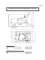
E-SERIES ELLIPTIMILL DIMENSIONS & WEIGHT
ELLIPTIMILL
ElliptiMills Boxed
E8
81” x 40” x 32”
E9
81” x 40” x 32”
Weight 500 lbs.
Weight 500 lbs.
ElliptiMills Unboxed (No box or Pallet)
E8
E9
Weight 450 lbs.
Weight 450 lbs.
PAGE 27
111 Canfield Avenue • Randolph, New Jersey 07869 • 1-800-LANDICE • FAX 973-927-0630
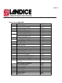
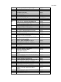
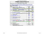
Parts List for ElliptiMill
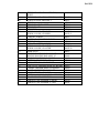
1
2
3
4
5
6
7
8
9
10
11
12
13
14
14A
15
16
17
18
19
20
21
22
23
24
25
26
27
28
MOTOR COVER ASSEMBLY
ROLLMENTUM
CLIP, PLASTIC COVERS
MOTOR COVER SCREWS
TRACTION STRIP
SHROUD, INSIDE, RIGHT
SHROUD, INSIDE, LEFT
SHROUD, OUTSIDE, RIGHT
SHROUD, OUTSIDE, LEFT
SHROUD SCREWS
FRAME ENDCAP, RIGHT
FRAME ENDCAP, LEFT
SHROUD DISC
TRANSFORMER
RELAY BOARD
BELT
MAGNETIC FLYWHEEL ASSEMBLY
TENSION ROLLER BRACEKT ASSEMBY
BRAKE MOTOR Assembly
LEVELING FOOT
REAR STEP ASSEMBLY
SCREWS, REAR STEP OUTTER
SCREW, REAR STEP MIDDLE
CRANK SHAFT ASSEMBLY
DRIVE PULLEY ASSEMBLY (attached to
drive belt)
DRIVE WHEEL ASSEMBLY
CRANK ARM PINION
WHEEL WASHER
PINION SCREW
PEDAL ROLLER
CRANK NUT
CRANT SCREW
CRANK CAP
81027
70519
81056
81041
81037
81031
81030
81029
81028
81041
81026
81025
81042
81038
82000
81036
81004
81032
81033
81018
81000
MISC
MISC
81003
81034
81035
MISC
MISC
MISC
MISC
MISC
MISC
MISC
PAGE 28
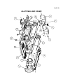
29
30
31
32
33
34
35
36
37
38
39
40
41
42
43
44
45
46
47
48
49
50
51
52
53
54
55
56
57
58
59
60
2.5 MM ALLEN HEAD SET SCREW
CRANK BEARING ALLEN BOLT
ISOLATION BEARING
BEARING SPACER
CRANK ARM SPACER
PINION BOLT
CRANK BEARING
TOP, READING RACK
RIGHT, READING RACK BUCKET
EXECUTIVE TRAINER MEMBRANE
CARDIO TRAINER MEMBRANE
PRO TRAINER MEMBRANE
RIGHT, CONTROL END CAP
LEFT, CONTROL END CAP
CONTROL END CAP SCREWS
ACCUTRACK HANDRAIL SCREWS
CROSSBAR, CHR ASSEMBLY
HANDRAIL COVER
(TOP COVER) PART OF CENTRAL
SHAFT COVER ASSEMBLY
(BOTTOM COVER) PART OF CENTRAL
SHAFT COVER ASSEM
RIGHT, SIDE HANDRAIL ASS’Y
LEFT, SIDE HANDRAIL ASS’Y
MOUNTING HANDRAIL SCREWS
PEDAL
FOOTPAD
PLASTIC PEDAL ASSEMBLY
MOVING HANDLE BAR
ASSEMBLY,RIGHT
MOVING HANDLE BAR ASSEMBLY,
LEFT
LOWER STRIDE ARM COVER, INNER
PEDAL SCREWS
CRANK ARM ALLEN BOLTS
LOWER STRIDE ARM COVER, OUTER
PEDAL TUBE ASSEMBLY, RIGHT
PEDAL TUBE ASSEMBLY, LEFT
UPRIGHT ALLEN HEAD BOLTS
UPRIGHT END CAP ASSEMBLY
STRIDE CRANK ARM ASSEMBLY,
RIGHT
STRIDE CRANK ARM ASSEMBLY, LEFT
RIGHT STRIDE ARM
LEFT STRIDE ARM
MISC
MISC
MISC
MISC
MISC
MISC
81047
70522-TOP
70522-BUCKETR
82001
82002
82007
81055
81054
MISC
MISC
81001
MISC
81023
81023
81005
81006
MISC
81044
81045
81019
81010
81009
MISC
MISC
MISC
MISC
81007
81008
MISC
81024
81017
81016
MISC
MISC
PAGE 29
61
62
63
64
65
66
67
68
69
70
71
72
73
74
75
76
77
78
79
80
81
82
STRIDE/CRANK ARM ASSEMBLY,
RIGHT
STRIDE/CRANK ARM ASSEMBLY, LEFT
LOWER STRIDE ARM BOLT
SPRING
SPRING PLATE WASHER
SPRING PLATE
T-HANDLE
STRIDE COVER, RT INNER
STRIDE COVER, LF INNER
UPRIGHT TOWER
HANDRAIL MOUNTING BOLTS
STRIDE KNOB
LINKAGE OUTTER SCREW
STRIDE COVER, RT OUTER
STRIDE COVER, LF OUTER
DOME PLUG
MOVING HANDLE BAR ASSY RT
MOVING HANDLE BAR ASSY LF
MOVING HANDLE BAR COVER
BOTTOM, READING RACK
LEFT, REDING RACK BUCKET
EXECUTIVE TRAINER DISPLAY BOARD
CARDIO TRAINER DISPLAY BOARD
PRO TRAINER DISPLAY BOARD
LOWER STRIDE ARM NUT
BOTTOM CONSOLE COVER ASSEMBLY
CRANK SHAFT ASSEMBLY
LINKAGE CAP ASSEMBLY, RIGHT
LINKAGE CAP ASSEMBLY, LEFT
81016
81017
MISC
MISC
MISC
MISC
MISC
81022-I
81021-I
MISC
MISC
MISC
MISC
81022-O
81021-O
MISC
81010
81009
81040
MISC
MISC
82003
82004
82008
MISC
81002
81003
81022
81021
PAGE 30
ELLIPTIMILL BED FRAME
PAGE 31
ELLIPTIMILL CRANK ASSEMBLY
PAGE 32
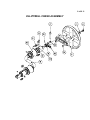
ELLIPTIMILL UPRIGHT
PAGE 33
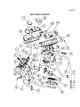
ElliptiMill Parts Assembly
PAGE 34
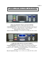
E-SERIES CONTROL PANEL & FEATURES
EXECUTIVE TRAINERS ARE ON ALL E8 & E9 MODELS
Production Date: February 12, 2008 Serail#’s E8-1013, E9-1010
Control Panel Features: 8.5 inch computer-animated video display, Chest Strap and
Contact Heart Rate Crossbar, 5 Built-in programs, 5 User-defined programs, 6 Fitness
Tests: Balke, Firefighter, Army, Navy, USMC, & USAF.
Electronics: Relay board, Brake controller.
Home & Commercial Settings: Level 1-20 Effor Levels, MPH, REV/MIN, or KMH
CARDIO TRAINERS ARE ON ALL E8 & E9 MODELS
Production Date: February 12, 2008, Serial#’s E8-1005, E9-0102
Control Panel Features: LCD Display windows, Chest Strap and Contact Heart Rate
Crossbar, 5 Built-in Programs, 5 User-defined programs, 3 Fitness Tests: Balke,
Firefighter, & Army. 2 Built-in heart rate monitoring programs, 2 User-defined heart rate
monitoring programs.
Electronics: Relay board, Brake controller.
Home & Commercial Settings: Level 1- 20 Effor Levels, MPH, REV/MIN, or KMH.
PAGE 35
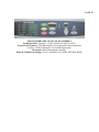
PRO TRAINERS ARE ON ALL E8 & E9 MODELS
Production Date: February 13, 2008, Serial#’s E8-1008, E9-1023
Control Panel Features: LED digit display, Chest Strap and Contact Heart Rate
Crossbar, 5 Built-in Programs, 2 User-defined programs.
Electronics: Relay board, Brake controller.
Home & Commercial Settings: Level 1-20 Effort Levels, MPH, REV/MIN, KMH.
PAGE 36
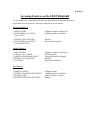
Accessing Features on the E8/E9 Elliptimill
To access functions, turn treadmill off and press and hold first button listed then press
next button listed. Release ALL buttons at same time to access feature.
Executive Trainer 2
1) MENU/START
2) MAIN MENU go to SETUP
Go to UNITS
Diagnostic mode & Open Loop
Configures Metric or English
3) EFFORT -/PAUSE/START
5) MAIN MENU go to SETUP
Go to RESET STAT
Reboots
Resets hours and miles
Cardio Trainer 2
1) NEXT/START
2) “Display + & -“/START
3) MANUAL/PROGRAM/START
4) EFFORT -/PAUSE/START
5) 1/5/START
Diagnostic mode & Open Loop
Self-Diagnostics
Configures Metric or English
Reboots
Resets hours and miles
Pro Trainer 2
1) DISPLAY/START
2) EFFORT -/WEIGHT INPUT/START
3) PAUSE/START
4) WEIGHT INPUT/PAUSE/START
Diagnostic mode
Configures Metric or English
Display Software version
Reboots
PAGE 37
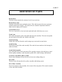
DEFINITION OF PARTS
Brake Motor
The brake motor controls the resistance level of your work out.
Brake Motor Cable
Attaches to the brake motor and brake wheel. This cable increases/decreases resistance
when the brake motor engages. The cable will move internal components inside the
brake wheel to adjust your resistance.
Central Shaft Cover
The cover is placed over the wheel and crank shaft and is held in by two screws.
Crank Arm
The crank arm attaches to the crank shaft and stride arm assembly. This arm corresponds
the movement of the stride arm with the crank shaft.
Isolation bearing
Isolates the crack arm from the crank bearing to prevent metal on metal noise.
Crank bearing
The bearing is part of the crank assembly. The crank side arm attaches to the bearing for
stride movement.
Crank Shaft Assembly
The crank shaft allows stride movement. The assembly consists of the shaft, drive wheel
& drive pulley assembly, crank arm pinion, pedal roller, crank bearings, and hardware.
Crossbar Control Heart Rate (C.H.R.)
Heart contact handgrip will provide the user heart rate reading during use.
Drive Belt
The drive belt will rotate the drive pulley assembly and braking system.
Drive Pulley Assembly
Drive belt attaches to this assembly. Also consist of the arm pinion. This controls rotation
to the crank shaft assembly.
PAGE 38
Drive Wheel Assembly
Attaches to the arm pinion and crank assembly. The assembly will run concurrently with
the crank shaft. This assembly is on the opposite side of the drive belt.
Faceplate
This overlay is found on the Pro Trainers models and is screwed onto the Upper Display
Board.
Footpad
Cushion for user’s feet.
Harness, Main upper
Transmit data from the upper board to the relay board.
HRC Dual Receiver
Takes transmission signals from the chest strap or CHR crossbar and converts it to a
digital signal to display heart rate info on your upper console.
Leveling Foot
The ElliptiMill will have 6 leveling feet to level the equipment and prevent it from
rocking.
Linkage Cap Assembly
These covers are placed over the adjustment knob to protect the parts that adjust the
stride length.
Lower Bracket Cover Assembly
The caps cover where the pedal tube and stride are bolted.
Magnetic Brake Wheel
The brake wheel provides mechanical resistance for user’s performance. The brake
wheel uses magnetic force to provide mechanical resistance for level of performance.
Moving Handlebar Assembly
Attaches to the stride arm which allows your arms to move with your stride.
Pedal Tube
This bolts to the end of the stride arm and rides on the pedal roller. This part takes the
force from the customers stride and in turn moves the crank arm & shaft to create an
elliptical motion.
PAGE 39
Rear Step
This platform is located at the rear of the ElliptiMill.
Relay Board
This part powers up the upper board and sends command to the brake motor for
resistance.
Stride Crank Arm Assembly
The stride arm gets bolted to a dowell on the upright. The moving handrails, crank arm
and pedal tube attach to this arm. The arm is adjustable for user comfort.
PAGE 40
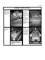
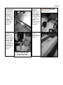
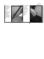
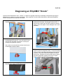
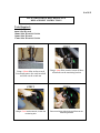
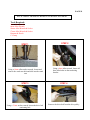
Diagnosing an ElliptiMill “Knock”
Cyclical noises described as “ticks”, “knocks”, or “clanks” are typically caused by an assembly oversight that can easily be
adjusted by the customer or a service technician. After trying each corrective action listed below, operate the ElliptiMill to
check if the reported noise has been eliminated.
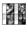
1. Loosen and retighten both stride adjustment
knobs and T-handles.
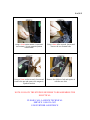
4. Check the pedal arms. Pick up each pedal arm by the
pedal about waist high. Gently jiggle it side-to-side. If
the joint at the other end of the tube (circled in red) feels
sloppy, remove the plastic covers and tighten the nut bolt
assembly.
2. Check all leveling feet. They should all be firmly
pushing against the ground. If you can hand turn any
of them, turn them down into the floor until they are
pushing firmly against the ground.
Also, check to see that all the nuts above the feet are
turned tightly up into the frame.
5. Crank to Crank Arm alignment check. Loosen the locking
collars (circled in red) and crank bearing screws (circled
in green). Get on the machine and operate it for about
60 seconds. Retighten the locking collars while pushing
the bearing assembly together so there are no gaps.
Finally, retighten the crank bearing screws.
3. Check the front wheels by jiggling them side-to-side. If
they are noisy, tighten the nut bolt assembly.
PAGE 41
ISOLATING NOISES
TOOLS NEEDED:
•
•
•
•
•
•
Automotive stethoscope or long flat head screwdriver.
10-17mm allen key and socket set.
Ratchet
Adjustable wrench
Phillip’s head screwdriver or drill bit.
Cordless drill.
Intro
Noises can be difficult to diagnose due to the fact that knocking, clunking,
banging, or ticking noises resonate throughout the whole machine. Follow these steps to
pinpoint which component is noisy.
Diagnostic Steps
1st: Determine which side the noise is coming from by using the machine. If you can’t
pinpoint the noise then take off the right side stride & frame covers. Then loosen the red
t-handle and rotate the machine. Did you hear the noise?
NO: REPLACE CRANK ARM
YES: PROCEED TO NEXT STEP
2nd: Tighten the red t-handle and then disconnect the 4 socket head cap screws at the
bottom right side of the crank arm. Spin the bearing that it connects to and see if the
noise present. Is the noise present?
YES: REPLACE THE CRANK BEARING
NO: PROCEED TO NEXT STEP
3rd: Reconnect the bottom part of the crank arm and lift up on the right foot rail. Spin
the pedal guide on the right side. Was the noise present?
YES: REPLACE THE PEDAL GUIDE.
NO: PROCEED TO NEXT STEP.
PAGE 42
4th: Take a long flat head screwdriver and place the flat-head end on the right side drive
wheel bearing. Then hold the handle part of the screwdriver up to your ear and spin the
drive wheel (using an automotive stethoscope will work as well). Did you hear the
noise?
YES: REPLACE THE DRIVE WHEEL BEARING.
NO: PROCEED TO THE NEXT STEP.
Step 1 thru 5 covers all the components on the right side of the machine. If the
noise is not found then follow these steps for the left side. If you went through both sides
and still can’t diagnose the noise then please contact the Landice Technical Service
Department @ 1-800-LANDICE (1-800-526-3423).
PAGE 43
TESTING COMPONENTS
1. BRAKE MOTOR:
Remove the brake motor from the drive pulley bracket and disconnect the harness. Then take out
the phillip head screws holding the dc motor in place and pull DC motor out. Using a digital
multimeter set to ohms (Ω), place your meter probes inside the clear insulation across the yellow and
orange wires. You are measuring resistance so you do no need to observe polarity.
- Turn knob of pot completely counter clockwise. Then slowly turn the knob clockwise and you
should measure 1.5Ω – 4.6K Ω.
- Turn knob of pot completely counterclockwise and you should measure 4.6KΩ – 1.5Ω
Now place meter probes across red and orange.
- Turn the knob of the pot completely clockwise. Then slowly turn the knob counterclockwise
and you should measure 4.6KΩ – 1.5Ω.
- Turn knob of pot completely clockwise and you should measure1.5Ω – 4.6KΩ.
Now place meter probes across yellow and red.
- Total resistance should be 4.6KΩ
2. RELAY BOARD:
The relay board runs on DC voltage. The DC voltage is delivered to the relay board from the J1
connector from the power pack. If the green +12V LED is illuminated then that means the relay
board is being powered from the power pack. If this LED does not come on, then check to make
sure AC voltage is coming out of the wall. After confirming voltage out of the wall, inspect the line
cord for any damage. If the condition of the line cord is fine, then check the connections from the
power pack to the relay board. If the connections are fine, then measure DC voltage from the J1
connector. Set your voltmeter to DC volts, place you red test lead at the back of the J1 connector
and your black test lead on any of the phillips head screws that mount the relay board into place.
You should measure at least 12Vdc. If the relay board is receiving DC voltage then it must be
replaced.
3. SPEED SENSOR:
The speed sensor can be checked for proper operation by entering DIAG mode (see page 36). There
is also a yellow SPEED LED soldered to the relay board. The LED will flash ON and OFF when
you rotate the drive pulley slowly by hand. This indicates proper operation of the speed sensor. If
you do not get this flashing to occur, then check for proper speed sensor gap and check connections.
If this does not help, then replace the speed sensor.
PAGE 44
4. UPPER DISPLAY BOARD:
The upper board is powered by DC voltage. DC voltage is supplied from the relay board. Confirm
the upper display board is getting DC voltage delivered to it. You can measure across the black and
green wires from the upper wire harness. If the display board is getting the proper DC voltage
supplied to it and it does not light, then perform a membrane bypass test for ET & CT Models (see
page 46). If it’s a PT then hit the START button manually to see if it turns on.
5. FACEPLATE:
Pro Trainer (PT) models utilize a faceplate. This part has no mechanical or electrical components
that can fail. However, if you press a key and it fails to respond check for proper display board
spacing. The faceplate is designed as a passive panel. When the user presses a key (pushes thru the
faceplate) they activate a switch mounted on the upper display board. If the display board to
faceplate distance is too great, the display board switch will not be fully activated and result in a
dead response.
6. MEMBRANE PANEL:
The membrane panel has small micro switches laminated inside that transmit the user’s commands
into treadmill functions. Enter “Diagnostic Mode” to confirm proper operation of the membrane
panel. In this test mode you will be able to check each key on the membrane panel by pressing a
key. What will happen is that you will hear an audible beep and also see a numeric code appear in
the main display window. There is a numeric code assigned to each key on the panel (except the
STOP key). For a complete list of these codes see the cart on page. If you do not hear a “BEEP” or
see the proper code appear, then the key is bad and the membrane panel must be replaced. The next
page will give you a listing of all the button feedback numbers for each machine.
PAGE 45
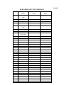
E8/E9 SERIES BUTTON FEEDBACK
1
Executive
Cardio
Pro
Trainer
Trainer
Traîner
LEFT 1
AGE
START
(TOP)
2
LEFT 2
0
PAUSE
3
LEFT 3
1
DISPLAY
4
LEFT 4 (BOTTOM)
START
PROGRAM
5
RIGHT 1
4
EFFORT (+)
EFFORT (-)
(TOP)
6
RIGHT 2
7
7
RIGHT 3
PAUSE
8
RIGHT 4
(BOTTOM)
DISPLAY -
9
BACK
WEIGHT INPUT
10
MENU
ENTER
11
NEXT
2
12
START
PROGRAM
13
PAUSE
5
14
EFFORT (+)
8
15
EFFORT (-)
16
UNITS (+)
NEXT
17
UNITS (-)
UNITS (-)
18
AGE
19
WEIGHT
3
20
0
EFFORT (-)
21
1
6
22
2
9
23
3
24
4
25
5
26
6
27
7
28
8
29
9
HRC BUTTON
30
ENTER
MANUAL
UNIT (+)
31
EFFORT (+)
32
DISPLAY +
WEIGHT INPUT
PAGE 46
ELLIPTICAL PT/CT/ET MEMBRANE BYPASS TEST
NOTE: +12-17Vdc must be confirmed across the black and green wires at the upper
connector on the wire harness to perform this procedure.
Tools Required:
• Phillips Head Screwdriver
• Digital Multimeter
• Jumper wire (only if your multimeter doesn’t have a continuity setting)
• Towel or bubble wrap.
Instructions:
1. Pull the console forward of the Velcro seal and then disconnect the membrane ribbon
cable.
2. Remove all the display board screws holding the upper board to the membrane.
3. Pop the upper display board off the membrane panel but leave the wire harness
connected to the upper board.
4. Lay your towel or bubble wrap inside the control panel frame and lay the upper board
face up.
5. Set your voltmeter to continuity and touch your two test leads together to make sure they
beep. Then proceed to follow the steps below to jump out the START & GND pins
which upper board application you’re working on.
FOR ET UPPER BOARDS:
View of upper
board when face
up
FOR CT UPPER BOARDS:
Jump the two end
pins
View of upper
board when face
up
Jump out these
pins
FOR PT UPPER BOARDS:
Once you lay the upper board on a towel the START button is already on it. Just press it
manually and if it doesn’t turn on the upper board is bad. If it does then it’s a mounting
issue.
PAGE 47
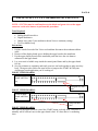
7. HEART RATE RECEIVER:
The heart rate receiver runs off of DC voltage supplied from the upper display board. The display
board will power the receiver by sending 5Vdc across the black and red wires. When the heart rate
system receives a transmission signal from the chest strap or Contact Heart Rate grips, it will send a
low DC voltage signal back to the upper board across the yellow and black wires. Please refer to the
heart rate diagnosis chart below for further info.
HEART RATE DIAGNOSIS:
CHR Grips Diagnosis:
1. There should be a constant 4.8-5.0Vdc across the red & black wires on CHR Grip
harness. If there is 0Vdc, then make sure that the upper board is powering the h/r
receiver board. Measure across RED & BLK wires at the UPDB. If you measure
0Vdc then the upper board is bad. If the upper board is sending 5Vdc to the
receiver but the receiver is not sending 5Vdc to the CHR grips then the receiver is
bad.
2. If the CHR Grip’s are working properly this is what you should see with your
voltmeter (not touching the grips):
WIRES
RED & BLACK
RED & WHITE
BLACK & WHITE
TABLE A
Vdc
5Vdc
0Vdc
4.85Vdc
OHMS
No reading
No reading
1.67M ohms
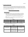
If the CHR Grip is working properly with a Pulse Simulator or when touching the
grips, this is what you should see on your meter:
WIRES
RED & BLACK
RED & WHITE
BLACK & WHITE
TABLE B
Vdc
OHMS
5Vdc
No reading
Voltage fluctuation between
No reading
3.2V – 4.6Vdc *NOTE:
Fluctuation will get faster as
you increase heart rate*
Voltage fluctuation between 4.5M – 23M ohms *NOTE:
.3V – 1.5Vdc *NOTE:
Fluctuations will get faster
Fluctuation will get faster as
as you increase the heart
you increase heart rate*
rate*
PAGE 48
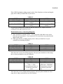
If the CHR Grip is not working properly with a Pulse Simulator or when touching the
grips, this is what you should see on your meter:
TABLE C
WIRES
Vdc
OHMS
RED & BLACK
5Vdc
No reading
RED & WHITE
3.2Vdc (reading will be
No reading
steady)
BLACK & WHITE
.3Vdc (reading will be
4.5M ohms (reading will be
steady)
steady)
If you the get readings from TABLE B and the console won’t output a heart rate
reading then the upper board has failed.
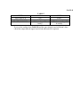
Heart Rate Receiver / Chest Strap Diagnosis:
1. There should be a constant 4.5Vdc – 5Vdc across the red & black wires on the
heart rate receiver harness. If you measure 0Vdc across those two points then the
upper board is bad.
2. If the upper board is working properly, this is what you should see on your
voltmeter (not touching the grips)
WIRES
RED & BLACK
RED & YELLOW
BLACK & YELLOW
TABLE A
Vdc
5Vdc
4.3Vdc
0Vdc
OHMS
0 ohms
0 ohms
9.85M ohms
If the heart rate receiver is working properly with your pulse simulator or chest strap,
this is what you should see on your voltmeter:
WIRES
RED & BLACK
RED & YELLOW
BLACK & YELLOW
TABLE B
Vdc
5Vdc
4.3Vdc
Voltage will fluctuate from
.6Vdc – 1.4Vdc
(Fluctuation gets faster as
you increase your heart
rate)
OHMS
0 ohms
0 ohms
Ohms will fluctuate from
9.85M ohms – 20M ohms.
(Fluctuation gets faster as
you increase your heart
rate)
If the heart rate receiver is not working properly with your pulse simulator or chest
strap, this is what you should see on your voltmeter:
PAGE 49
WIRES
RED & BLACK
RED & YELLOW
BLACK & YELLOW
TABLE C
Vdc
5Vdc
4.2Vdc
.6Vdc (reading will be
steady)
OHMS
0 ohms
0 ohms
9.85M ohms (reading will
be steady)
If you get the readings from TABLE B and the upper display board still doesn’t show
a heart rate output then the upper board is bad and needs to be replaced.
PAGE 50
REMOVAL AND REPLACEMENT OF COMPONENTS
CRANK ARM (Removal):
1. Take the set screw out for the adjustment knob completely out and then remove
the adjustment knob by turning it counterclockwise.
2. Remove the red handle by turning it counterclockwise.
3. Take out all the phillips head screws for the stride adjustment cover. (See Figure
A)
4. Remove (4) #6 Socket Head Caps screws at the bottom where crank arm meets
the crank.
Screws are
on backside
Screws for
front side
(Figure A)
CRANK ARM (Install):
1. Follow the reverse of removal instructions to install new crank arm but don’t
install the stride adjustment cover.
2. To set up crank arm:
a) Tighten the red handle at the top of the assembly. Then turn the red
handle counterclockwise 5.5 turns.
b) Rotate the crank assembly and watch the top of the crank to see if it hits
up against the red handle and stride bar (See Figure B).
c) If not or little movement then tighten the red handle down and proceed to
step d. If it hits both sides then you will have to replace the crank arm.
d) Install stride adjustment cover.
e) Install stride adjustment knob and then set screw.
Step b is to check the
deflection by 5mm. If
it hits both sides then
crank arm is bad.
5mm
deflection
(Figure B)
PAGE 51
CRANKSHAFT REMOVAL & REPLACEMENT
INSTRUCTIONS
Tools Required:
10mm Allen Wrench
6mm Allen Wrench
2.5mm Allen Wrench
10mm Socket & Socket Wrench
Phillips Head Screw Driver
Rubber Mallet
Instructions:
1. Remove the crankshaft covers on both sides by removing the two Phillips head
screws located on the covers.
2. Using a 6mm Allen wrench, remove the eight screws that hold both of the crank
arms in place on the crankshaft.
3. Using a 10mm Allen and socket wrench, remove the two main crankshaft bolts
located on either side of the crankshaft and remove.
4. Using a 2.5mm Allen wrench, loosen the two setscrews that hold the retaining
collar in place. Using your rubber mallet gently tap off and remove the retaining
collar from the crankshaft.
5. Slide out and remove the crank bearing and the plastic collar from the crankshaft.
6. Using your rubber mallet, gently tap the rubber rollers downward to remove them
from the crank arm.
7. Using the 2.5mm Allen wrench, loosen the two setscrews that hold the last
retaining collar on the crankshaft. Using your rubber mallet gently tap off and
remove the retaining collar from the crankshaft.
REVERSE PROCESS 7 THRU 1 TO INSTALL THE NEW CRANKSHAFT.
PAGE 52
ELLIPTIMILL DRIVE BELT REMOVAL &
REPLACEMENT INSTRUCTIONS
Tools Required:
4mm Allen Wrench
6mm Allen Wrench
10mm Allen Wrench & Socket
14mm Allen Wrench
17mm Allen Wrench & Socket
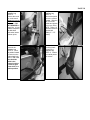
STEP 1
STEP 2
Using a 10mm allen socket wrench,
loosen and remove the crank arm bolt
and slide out the crank arm
Using a 4mm allen wrench, loosen all three
Allen bolts on the tensioning bracket
STEP 3
STEP 4
Using a 17mm socket wrench, loosen the
tensioning bolt
Remove all three allen bolts and Remove the
tensioning bracket
PAGE 53
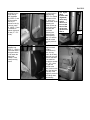
STEP 5
STEP 6
Using a 10mm socket wrench, loosen and
remove both 4 ½ inch magnetic flywheel
bracket bolts
Using a 6mm allen wrench, loosen and
remove the two bottom bolts
STEP 7
STEP 8
Using a 14mm socket wrench, loosen and
remove the nut and remove the magnetic
flywheel bracket
Remove the old drive belt and replace it
with the new belt.
NOTE: FOLLOW THE STEPS IN REVERSE TO REASSEMBLE THE
ELLIPTICAL.
PLEASE CALL LANDICE TECHNICAL
SERVICE 1-800-526-3423
FOR FURTHER ASSISTENCE
PAGE 54
ELLIPTIMILL BEARING REMOVAL & REPLACEMENT
Tools Required:
4mm Allen Wrench
6mm Allen Wrench
10mm Allen Wrench & Socket
17mm Allen Wrench & Socket
Hammer & Punch
C-Clamp
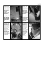
STEP 1
Using a 10mm allen socket wrench, loosen and
remove the crank arm bolt and slide out the crank
arm
STEP 3
Using a 17mm socket wrench, loosen the drive belt
tensioning bolt
STEP 2
Using a 4mm allen wrench, loosen all
three allen bolts on the tensioning
bracket
STEP 4
Remove the drive belt from the drive pulley
STEP 5
STEP 6
Using a 6mm allen socket loosen and remove the
drive pulley bolt
Remove the drive pulley from the elliptical
STEP 7
STEP 8
Using a hammer and a flat head set punch knock out
the bearings on either side of the elliptical
Using a fine grit piece of sandpaper clean off any
residue left in the hub of the elliptical
Apply a little grease on the hub of the elliptical
and bearing
STEP 9
STEP 10
Using a hammer gently tap both bearing in place on
either side of the elliptical
Using a clamp and two pieces of wood press the
bearings back into place
NOTE: FOLLOW THE STEPS IN REVERSE TO REASSEMBLE THE
ELLIPTICAL
PLEASE CALL LANDICE TECHNICAL SERVICE 1-800-526-3423
PAGE 56
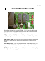
LED CONFIGURATIONS: RELAY BOARD
The relay board is designed with diagnostic LED lights. The LED’s are color coded according
to their specific function. Green indicates should always be ON when power is supplied to the
elliptical. Here is a list of each LED and whit it signifies:
+12V (green) – The +12V LED illuminates when DC voltage is being supplied to the relay
board. The power pack takes the AC voltage from the wall, converts it to DC voltage and sends
it to the relay board.
BSW+ & BSW- (red) – These LED’s tell you if the upper board is sending a signal to close
the relays on the board. When the LED lights, it tells you that the coil on the relay is being
energized.
MTR+ & MTR- (red) – These LED’s illuminate when DC voltage is being supplied to the
brake motor. When this LED lights, it tells us that the relay has energized and sending DC
voltage to the brake motor.
SPEED (yellow) – The speed LED flashes on and off (relative to rotation of the drive pulley)
when the speed sensor is operating properly.
PAGE 57
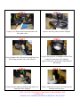
Calibration Instructions for Brake Controller
Tools Needed: Phillips Head Screw Driver.
Instructions:
1. Release the brake cable from the controller. To do so, pull on the brake cable to
give it some slack, unwrap it around the white brake controller knob and pop it
out of the notch.
2. Remove the two black phillip’s head bolts that hold the brake controller to the
bracket on the machine.
Screws for DC
Motor.
3.
Take the two screws out for the dc motor that’s located at the
base of the brake controller. Then slide the dc motor out of the
assembly.
4. ENTER DIAGNOSTIC MODE:
• ON ET’s: Press MENU & START simultaneously.
• ON CT’s: Press NEXT & START simultaneously.
• ON PT’s: Press DISPLAY & START simultaneously.
5. Set the effort level screen to 20.0
6. Turn the white knob for the pot counterclockwise until the reading in the display
reads 20.0. **(See Fig. A)**
7. Insert the brake cable back into the notch on the white knob, wrap it around in a
counterclockwise direction from the notch and bolt it back down to the machine
**(See Fig. B)**
PAGE 58
NOTE: YOU MAY HAVE TO ADJUST THE KNOB ON THE BRAKE
CONTROLLER AS WELL AS THE BRAKE CABLE TO GET THE TRUE
RESISTANCE. HERE’S HOW:
1. First, bring the resistance down from 20 to 1 and make sure the white nylon piece
touches the bottom of the green part of the brake system **(See Fig. C)**. If it
touches, then it’s set to effort level 1.
2. Then bring it back to effort level 20 and make sure the white nylon piece touches
the top of the brake system. If so then level 20 is set.
3. After this is performed, check to make sure that there is no slack on the brake
cable. If the cable has some slack, then loosen the locking nut and turn the
turnbuckle in a clockwise direction to get rid of the slack. If the brake cable is too
tight then turn the turnbuckle counterclockwise to give it some slack (See Fig. D).
Figure A
Turn the knob
counterclockwis
e to set the
brake control
setting. Use the
notch to know
which direction
to turn.
Figure B
Once the brake
cable is inserted
into the notch
on the brake
assembly,
rotate the brake
cable in a
counter
clockwise
direction
Make sure
notch lines up
with screw
See arrow. If
not then take
out the screw in
the center of the
knob and
reposition it and
screw it back
down
Figure C
Effort Level #1 / Effort Level# 20
Figure D
Loosen the locking
nut for the
turnbuckle. To
remove slack, turn
the buckle
clockwise. To
obtain slack turn it
counterclockwise
PAGE 59
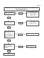
PRESS START, MACHINE WONT TURN ON, NO LIGHTS TO
THE UPPER DISPLAY
Is the GREEN LED on
the power pack lit?
NO
1. Check to make sure
120Vac is coming out
of the wall outlet.
2. Replace Power Pack.
YES
Is the GREEN +12V
LED on the relay board
lit?
NO
1. Check the connections
at the power pack.
2. Replace relay board.
YES
Unplug the wire harness
for the console and
check connections at
both ends of the harness.
Is the wire harness in
tact?
NO
Replace the wire harness.
YES
Perform Membrane
Bypass Test on page# .
Did the upper board
light up?
YES
Replace Membrane Panel.
NO
Replace Upper Board.
PAGE 60
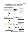
DISPLAY LIGHTS UP, START TO USE THE MACHINE BUT
THERE IS NO SPEED FEEDBACK IN SPEED WINDOW.
Take off the cover at the front of the
machine and the left outside frame
cover. Locate the speed sensor at the
bottom right hand side of frame by
the drive wheel. Then check the gap
of the sensor. Is it out of position?
Adjust sensor:
1. Loosen phillips
head screw that
holds sensor in
place.
2. Adjust gap to
3/8th of an inch.
3. Tighten phillips
head screw.
YES
NO
Unplug the speed sensor from
harness and check for loose wires.
Any found?
If found on harness end,
replace the harness. If
found on sensor end
then replace the speed
sensor.
YES
NO
Spin the drive wheel by hand and
check on the relay board to see if the
YELLOW SPEED LED flickers.
Does the SPEED LED flicker?
NO
Replace speed sensor.
Check the main wire
harness going to the
display. Any loose
wires found?
YES
NO
Replace Upper Board.
YES
Replace wire
harness
PAGE 61
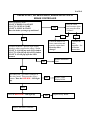
PRESS START, NO RESISTANCE, ERROR DETECTED IN
BRAKE CONTROLLER
Enter Diagnostic Mode:
ON PT’S: DISPLAY & START
ON CT’S: NEXT & START
ON ET’S: MENU & START
Does the brake system go up and down?
Does the effort
level increase when
you press the effort
+ button?
YES
NO
YES
NO
Check the harness for
loose connections and
reset the connections.
Does the effort
change?
Is button feedback # present in the display
windows when you press the effort + button.
ON ET’S: #14 will pop up in LCD window
ON CT’S: #20 will pop up in LCD window
ON PT’S: #5 will pop up in the LED
window
Replace Membrane
Panel.
NO
YES
Disconnect the 7-pin white connector at
the relay board. Then press the effort +
button. Does the RED BSW+ LED light
up.
NO
Replace Upper
Display Board.
YES
Does the RED MTR+ LED light up.
Replace the Brake Controller
NO
Replace Relay Board.
Calibrate the
brake
controller. See
calibration
instructions
PAGE 62
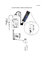
ELLIPTIMILL WIRE SCHEMATIC
AG
E
0
1
4
7
2
5
T
8
TE
R
IGH
EN
WE
3
6
9
ST
TA
AR
RT
T
PA
P
AU
US
SE
E
OFF
O
FF
MA
NU
AL
C
PROG
RAMS
SE
LE
CT
HR
PAGE 63
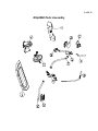
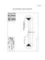
ELLIPTIMILL MAIN HARNESS
PAGE 64
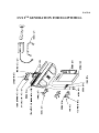
LVS 2ND GENERATION FOR ELLIPTIMILL
PAGE 65
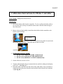
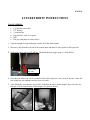
LVS2 RETROFIT INSTRUCTIONS
TOOLS NEEDED:
•
•
•
•
•
•
6/32 drill bit (starter bit).
3/8th drill bit.
½ inch drill bit.
Tape measure, ruler, or t-square.
Drill
Fine grit sand paper to remove burr’s.
1. Take the upright end caps and upper console off of the control panel.
2. Measure 1 inch from the left side of the control panel and mark it with a pencil to drill your hole.
3. Drill in the center using a 6/32 drill bit. Then drill the hole bigger using a ½ inch drill bit.
1 inch from
left side.
4. Now that you drilled out your access hole for the cable and power wires, clean of any burr’s from the
hole using fine grit sandpaper and run your wires thru.
5. After fishing the wires thru the access hole, slide them thru the left side upright. They will come out
thru the u cut out at the bottom of the upright. (See pictures below).
PAGE 66
6. Next take off the outer left stride cover. You will need to drill out holes for the cable & power
connector’s. Measure 3 ½ inches from the bottom of the stride cover, in line with the bottom left
hole for the mounting screw, and mark it with a pencil to drill your hole. Use a 6/32 drill bit as a
starter hole. Then drill it out using a 3/8th’s drill bit.
7. Now measure 2 ½ inches from the bottom of the stride cover, in line with the bottom left hole for the
mounting screw and mark it with a pencil to drill your hole. Use a 6/32 drill bit as a starter hole.
Then drill it out using a ½ drill bit. Refer to the picture below for steps 6 & 7.
Cable
connector
3.5 inches
from
bottom
(3/8 hole)
Power
connector
2.5 inches
from
bottom (½
hole).
8. Remount the stride cover back onto the elliptimill and make your connections. Turn the LVS DVD
player on and test it out.
PAGE 67
INDEX
Accessing Diagnostic Features
PT…………………………………………………….Page 36
CT…………………………………………………….Page 36
ET…………………………………………………….Page 36
Assembly Instructions
Assembling Elliptimill………………………………...Page 15-21
DCP Instructions…………………………………….Page 22
LVS2 Instructions…………………………………....Page 23-25
LVS2 RetroFit Instructions………………………….Page 65-66
Bearings
Crank Bearing………………………………………..Pages 31, 37, 51
Isolation Bearing……………………………………..Page 31
Brake Controller
Parts Definition……………………………………....Page 37
Calibration…………………………………………...Page 57, 58
Flow Chart…………………………………………...Page 61
Button Feedback…………………………………………….Page 45
Crank Arm
Exploded View of Parts……………………………....Page 29, 31
Parts Definition……………………………………….Page 37
Removal/Replacement………………………………..Page 50
Drive Belt
Parts Definition………………………………………..Page 37
Removal/Replacement…………………………………Page 52, 53
Drive Pulley
Exploded View of Parts……………………………….Page 31, 33
Parts Definition………………………………………..Page 37
Drive Wheel
Exploded View of Parts……………………………….Page 31, 33
Parts Definition………………………………………..Page 38
Removal/Replacement………………………………...Page 54, 55
PAGE 68
Faceplate
Parts Definition………………………………………..Page 38
Testing Component…………………………………....Page 44
Flowcharts
Brake Controller………………………………………Page 61
Speed Sensor……………………………………………Page 60
Upper Display…………………………………………..Page 59
Harness, Main upper
Parts Definition…………………………………………Page 38
Wiring Schematic……………………………………….Page 63
HRC Dual Receiver
Parts Definition………………………………………….Page 38
Testing Component……………………………………...Page 47, 48, 49
LVS2
Assembly Instructions…………………………………...Page 22
RetroFit Instructions…………………………………….Page 65, 66
Pedal Tube
Exploded view of parts…………………………………..Pages 28, 33
Parts Definition……………………………………………Page 38
Rear Step
Exploded view of parts…………………………………..Pages 27, 33
Parts Definition…………………………………………..Pages 39
Relay Board
LED configuration……………………………………….Page 56
Parts Definition…………………………………………..Page 39
Testing Component………………………………………Page 43
Stride Crank Arm
Exploded view of parts…………………………………..Page 28, 33
Replacement/Removal……………………………………Page 50
Wiring Schematics
Elliptimill Wire Schematic………………………………Page 62
LVS2 Schematic………………………………………….Page 64
Main Wire Harness………………………………………Page 63