1
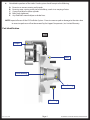
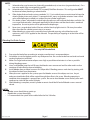
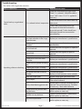
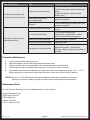
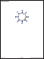
Disc Brake System
For Trailers
SERVICE MANUAL
Rev: 01.30.2015
Page 1
DISC BRAKE SYSTEM FOR TRAILERS SERVICE MANUAL
TABLE OF CONTENTS
Disk Brakes for Trailers
Introduction
Safety Information
Part Identification
Brake System Attributes
Reversing valves
Bleeding the Brake System
Troubleshooting
Preventive Maintenance
Replacement Parts
8,000 Lb. Disc Brakes With Oil Lubrication Operation & Service
Getting Started – Set-up and Adjustment
Bearing Lubrication - Oil
Oil Cap and Oil Seal
Periodic Bearing Inspection
Spindle nut adjustment
Disc Brake Pads
Disc Brake Caliper
Wheel Torque Specifications
Rev: 01.30.2015
Page 2
3
3
3
4
5
5
6
7
8
8
9
9
9
9
9
10
10
10
10
DISC BRAKE SYSTEM FOR TRAILERS SERVICE MANUAL
Disk Brakes for Trailers
Introduction
Combining years of experience in the trailer frame and recreational vehicle industry with the newest and most
innovative technology, Lippert Components, Inc. steps up again with the addition of our new Disc Brake System for
Trailers.
The following publication is designed to give the customer an easy-to-understand operation and service manual to
provide useful and important information. The quality of the Lippert name and the finest materials utilized in the
production of the Disc Brakes provide for the finest trailer brake systems in the industry.
Quality comes threefold in Lippert Components, Inc.
•
•
•
The finest quality materials
The latest technology and design
The quality standards maintained from materials to final assembly
All three points provide the customer with the best product they can possibly buy and the satisfaction of knowing
they can trust the equipment on which they have spent their hard-earned money.
Lippert Components, Inc. thanks you for purchasing our Disc Brake System. When you speak of Lippert
Components, Inc., our quality stands beside you.
Safety Information
The “WARNING!” symbol is a sign that a service or maintenance procedure has a safety risk involved and may cause
death or serious injury if not performed safely and within the parameters set forth in this manual.
Always wear eye protection when performing service or maintenance to the vehicle. Other safety equipment to
consider would be hearing protection, gloves and possibly a full face shield, depending on the nature of the service.
This manual provides general service and maintenance procedures. Many variables can change the circumstances
of the service procedure, i.e., the degree of difficulty involved in the service operation and the ability level of the
individual performing the operation. This manual cannot begin to plot out procedures for every possibility, but will
provide the general instructions for effectively servicing the vehicle. In the event the skill level required is too high
or the procedure is too difficult, a certified technician should be consulted before performing the necessary service.
Failure to correctly service the vehicle may result in death or injury.
The owner’s manual for your unit may have more procedures for service and maintenance.
1.
2.
3.
4.
5.
Installation, maintenance, adjustment or repair of LCI Braking System should be performed by qualified
technicians only.
Be sure to support trailer with jack stands to safely perform brake installation, maintenance,
adjustment or repair.
Always test and confirm that trailer brakes are operating properly after every hookup and before actual
towing.
Know, or at least be familiar with, local and state laws regarding towed vehicle’s brake system and
any applicable laws and requirements. Remember to allow for extra stopping distance needed when
towing a trailer.
Disc brakes generally require more hydraulic pressure than drum brakes. Verify that the hydraulic
actuator will generate hydraulic pressure adequate to safely operate disc brakes.
Rev: 01.30.2015
Page 3
DISC BRAKE SYSTEM FOR TRAILERS SERVICE MANUAL
6.
Scheduled inspections of the trailer’s brake system should comprise the following:
A.
B.
C.
D.
E.
Excessive or uneven wearing on the pads.
Excessive wear, scoring, excessive heat build up, cracks in or warping of rotor.
Correct fluid level in master cylinder.
Bolts firmly tightened.
Any fluid leaks around calipers or brake lines.
Note: Inspect all areas of the LCI Disc Brake System. Excessive wear on pads or damage to the rotors due
to excessive pad wear will not be covered by the Lippert Components, Inc. Limited Warranty.
Part Identification
Fig. 1
Caliper
Rotor
Inner Bearing
Outer Bearing
Wheel Lug
Rev: 01.30.2015
Page 4
DISC BRAKE SYSTEM FOR TRAILERS SERVICE MANUAL
Brake System Attributes
Do not use petroleum based grease! Caliper seals, o-rings, etc., are installed using silicone lubricants.
Petroleum based lubricants are not compatible with these seals and o-rings and will cause failure.
Do not paint solenoid reversing valves! (for trailers with surge brakes only). This assembly uses
a floating caliper. Paint will inhibit caliper movement on guide bolt sleeves and on the caliper
mounting bracket.
Reversing valves
Utilizing surge brakes requires the use of a reversing valve. Disc brakes work equally well in forward or
reverse and the reversing valve allows for proper function. Factory installed surge disc brake actuator is
installed as standard equipment. Surge brake actuators without a solenoid reversing valve installed as
standard equipment will require the valve to be retro-fit. The solenoids are wired into the tow vehicle’s
back-up light circuit. These solenoids are found in two styles:
Normally Open - This solenoid valve is installed near the master cylinder added inline.
Advantages
• Ease of installation; not time consuming.
Disadvantages
• In a downhill disposition, positive pressure will remain in the brake line. When the tow vehicle is shifted
into reverse and the reverse lights are energized, the solenoid reversing valve traps the pressurized
brake fluid and may result in failure to back up the trailer.
• In the event the trailer abruptly contacts an obstruction, such as a curb or speed bump, while in the
process of backing up, force of this impact is transferred wholly to the master cylinder piston and can
easily damage a seal.
Normally Closed - This solenoid valve is installed into a T-fitting from the master cylinder.
Note: A “three port” valve is also available to eliminate the T-fitting. A return line from the valve MUST be
installed to return brake fluid into the master cylinder.
Advantages
• Eliminates the Disadvantages with “Normally Open” Valves.
Disadvantages
• Needs additional fittings, extra brake line, and requires drilling and tapping an access hole in the master
cylinder for the return line.
• Some OEMs install the return line in the fill cap of the master cylinder. This may allow a moisture to get
into the brake fluid.
Rev: 01.30.2015
Page 5
DISC BRAKE SYSTEM FOR TRAILERS SERVICE MANUAL
Note:
1.
2.
3.
4.
5.
6.
Solenoid valves may be one wire (internally grounded case) or two wires (ungrounded case). On a
two-wire model, they are not polarity specific.
Solenoid valves will have an IN and OUT to specify fluid flow direction. This configuration MUST
be observed when plumbing a solenoid valve.
Older hydraulic drum brake systems needed a 10 - 12 psi residual pressure maintained to keep the
wheel cylinder piston seals seated. To accomplish this, many surge brake actuators have a check
valve with diaphragm installed just inside of master cylinder output port.
Disc brake systems subjected to residual brake line pressure will overheat the brakes and hubs. Be
sure surge brake actuator is designed specifically for disc brakes and the check valve is rendered
inoperative. Use an ice pick or awl to perforate the diaphragm.
Never tow a surge braked trailer if the tow vehicle’s back up light circuit is ON at any time other
than when the tow vehicle transmission is in reverse.
When bleeding a system with a normally closed solenoid reversing valve, bleed one cycle
minimum, with 12 VDC applied to the solenoid. The possibility of trapping air at the valve will be
eliminated.
Bleeding the Brake System
Use only DOT3 brake fluid.
1.
2.
3.
4.
5.
6.
7.
Pressurize the brake lines according to actuator manufacturer’s recommendations.
Air bubbles rise to the highest point in any fluid power line. Be sure the brake lines are level and avoid
creating high points to hold air.
Make sure surge brake actuator calipers are as high as possible and actuator is as low as possible
during bleeding process.
Use a small bleeder hose that will fit over the bleeder screw on one end and the other end in a clear
container of brake fluid to observe bubbling.
Install bleeder hose on bleed screw on first caliper bled. Bleeding process works best by starting with
the caliper furthest from the actuator.
When pressure is applied to the system, open the bleeder screw at the caliper, one turn. Any air
and pressurized brake fluid will be vented through the orifice in the screw. Bleeding operation is
complete when trapped air is purged from system. Be sure to close bleeder screw securely after each
compression stroke of the master cylinder.
When bleeding is complete, master cylinder reservoir should be full and all bleeder screws secured
closed.
NOTES:
• Bleeder screw should always point up.
• Bleed brake system thoroughly.
• LCI recommends the system to be re-bled after the first 100 miles.
Rev: 01.30.2015
Page 6
DISC BRAKE SYSTEM FOR TRAILERS SERVICE MANUAL
Troubleshooting
* For trailers with surge brake actuators.
What Is Happening?
Why?
What Should Be Done?
Check tow vehicle back-up light circuit.
Check 12 v. solenoid. (Should be able to
hear a "click" when 12 v. DC is applied to
lead wire.)
Cannot back up surge braked
trailer.
Check connection to tow vehicle back-up
12 v. solenoid valve is inoperative. light circuit.
Check trailer ground connection (do
not depend on hitch ball connection
to provide ground.) Trailer should have
dedicated ground wire connected to
grounding lug.
This could be caused by a worn
out shock absorber in the Surge
Brake Actuator.
The linkage pivots on the brake
actuator.
Loose hitch ball.
Loose hitch.
Squeaking, clatter or chucking
Hitch ball worn or too small.
A bent push rod in the shock
absorber.
A bent master cylinder actuating
rod.
A damaged coupler assembly.
Broken rotor.
Low brake fluid level in master
cylinder.
Worn out caliper pads.
Leaky caliper.
Leaky wheel bearing grease seal.
Caliper/Mounting bracket bolts
may be loose.
Spindle nut may be loose.
Lug nuts may be loose.
Rev: 01.30.2015
Page 7
Replace per manufacturer's specifications.
Lubricate per manufacturer's
specifications.
Inspect hitch ball and tighten or replace as
required.
Inspect hitch and tighten or repair as
required.
Replace with properly sized and rated ball.
Replace per manufacturer's specifications.
Replace per manufacturer's specifications.
Replace per manufacturer's specifications.
Replace rotor and check calipers.
Fill and bleed brakes.
Replace or build actuator master cylinder.
Replace caliper pads and check rotors.
Replace or rebuild calipers.
Clean other hardware.
Replace grease seal and wheel bearings as
required. Pack wheel bearings. Re-bleed
as necessary. Clean other hardware.
Tighten to manufacturer's specifications
and/or replace as necessary.
Tighten to manufacturer's specifications
and/or replace as necessary.
Torque to manufacturer's specifications
and/or replace as necessary.
DISC BRAKE SYSTEM FOR TRAILERS SERVICE MANUAL
What Is Happening?
Why?
Caliper piston not retracting.
One brake overheating, side
pull, poor brake performance.
A bent guide bolt/caliper
mounting bracket.
Side pull.
Foreign material in brake line.
Low hydraulic fluid level.
All brakes overheating, poor
brake performance.
Broken or pinched brake lines.
Brake actuator frame damaged.
Residual pressure in brake line.
What Should Be Done?
Check for foreign material in brake line.
Check for corrosion between caliper and
piston.
Check and rebuild or replace caliper.
Bleed system.
Replace as required.
Check wheel bearings, caliper, rotor, and
replace as required.
Flush and clean thoroughly. Re-bleed
system.
Fill with new brake fluid per
manufacturer's specifications. Bleed
brakes to eliminate any trapped air.
Replace or repair as required.
Replace actuator.
Check Operating Manual for Electric
Hydraulic Actuators. Check wheel
bearings, caliper, and rotor and replace as
required.
Preventive Maintenance
1.
2.
3.
4.
5.
Visually inspect brakes before each trip.
After each hook-up, check trailer brake operation before travel.
Follow manufacturer’s recommendations for use and replacement of brake fluid.
Wash brake assembly immediately after exposure to salt water or other corrosives.
Occasionally check hub and assemblies to see they are within normal operating ranges (130º - 175º F).
Brake components may be much hotter than the hub or wheel, use caution during inspection.
Note: Refer to LCI's Trailer Axle Owners Manual for additional information regarding maintenance
schedule, suspensions, bearing repack instructions and wheel torque recommendations.
Replacement Parts
For Axle Service & Warranty or a list of replacement parts, please contact:
Lippert Components, Inc.
Axle Division, Plant 45
2703 College Ave.
Goshen, IN 46528
574-971-4100 ext. 4925
Rev: 01.30.2015
Page 8
DISC BRAKE SYSTEM FOR TRAILERS SERVICE MANUAL
8,000 Lb. Disc Brakes With Oil Lubrication Operation & Service
Getting Started – Set-up and Adjustment
For proper performance, all new axles should have the following checked at the specified intervals:
1.
2.
3.
Check tire pressure: Set to manufacturer’s recommendations, check weekly, check inflation pressure
cold before operation.
Check lug nut torque: On first trip, tighten wheel lug nuts at start and at 10, 25 and 50 miles and until
no torque loss occurs and full torque is maintained. Check lug nuts thereafter before each trip, after
any excessive braking and following winter storage. Be sure to repeat procedure should a wheel ever
be removed from the axle hub.
Oil level: Before every trip check to see that the oil level is up to the level indicated on the oil cap. A
low level can indicate a seal or cap leak.
Bearing Lubrication - Oil
Your axle bearings are lubricated with a SAE 80-90W hypoid gear oil. Periodically check and refill the hub as
necessary to the level indicated on the clear plastic oil cap. The oil can be filled through the cap by removing the
rubber plug. In order to check oil level, do so after unit has been parked for a few minutes.
Recommended Oil Lube for axle bearings:
Oil designation: SAE 90, SAE 80W-90, SAE 75W-90
Approved Sources:
Union Oil Co
Unocal MP Gear Lube
Exxon Co
Gear Oil GX 80W-90
Mobil Oil
Mobilube SHC 75W-90
Pennzoil Co
Gear Plus 80W-90 GL-5
Gear Plus Super 75W-90
Oil Cap and Oil Seal
The clear plastic oil cap should be tightened to 25 ft-lbs. Over-tightening can damage the sealing o-ring and cause
an oil leak.
In order to remove hub/rotor assembly a gear puller may be required. The oil seal is a 2 part seal where the inside
diameter of the seal presses onto the spindle journal and the outside diameter of the seal presses into the hub
bore. Therefore a gear puller is the most efficient way to remove hub from spindle. A new oil seal MUST be
installed before reassembly or the old seal will leak upon reinstallation and use. The National seal part number
is W370219BG or Transcom part number is OB2233749 for reference. When reinstalling a new oil seal, be sure to
correctly orientate the seal. Most are marked “AIR SIDE.” This side MUST not be placed towards the oil and bearing
or it will fail in service. Install new seal using a block of wood and hammer to drive the seal in the seal bore square
until the outer face of the seal is flush with the seal bore face. Do not use permatex on rubber encased oil seals.
Periodic Bearing Inspection
A physical bearing inspection should be conducted every 15,000 miles. An inspection of the bearing condition can
detect early bearing issues. Upon inspection bearings should look brand new and be able to be reassembled and
used if in this condition. If discoloration, pitting, corrosion, flat spots or some abnormal condition is observed the
bearing and race should be replaced at the same time. Bearings are available at auto part stores.
Rev: 01.30.2015
Page 9
DISC BRAKE SYSTEM FOR TRAILERS SERVICE MANUAL
Bearing Part Numbers:
Outer bearing cone
Outer bearing race
Inner bearing cone
Inner bearing race
02475
02420
25580
25520
Spindle nut adjustment
The proper method to assemble the spindle nut is as follows:
1. After hub installation onto spindle, install outer bearing.
2. Install spindle washer and thread on spindle nut with slots facing outward.
3. Tighten spindle nut with a pair of slip joint pliers to approx 50 ft-lbs.
4. Back off torque usually 1/4 turn so that you can finger tighten the spindle nut.
5. Finger tighten, drop cotter pin through slot and hole in spindle. If slot in nut does not align with hole
in spindle, back nut off until it does, never tighten past finger tight.
6. Bend legs over end of spindle and be sure legs do not interfere with oil cap upon reassembly.
Disc Brake Pads
Disc brake pads are available through auto part stores. You can ask for disc brake pad kit MD215. Brake pads are a
consumable item so be sure to visually check pads every 3,000 miles. Be sure to also check rotor surfaces visually
when you are checking the brake pads. Deep groves developing on one or both rotor surfaces can indicate a
caliper piston, slider bolt or residual pressure problem if this ever occurs. Brake rotors should be turned when disc
brake pads are replaced.
Disc Brake Caliper
The proper mounting torque for the disc brake caliper mounting bolts is 40-50 ft-lbs. If these are removed
for servicing the brake system, add blue thread locking compound to the threaded area of the bolt at time of
reassembly. Also lubricate the inside of caliper bushings that the slider bolts go through. Be sure to only use
silicone based grease. The rubber bushings are not compatible with petroleum based greases.
Wheel Torque Specifications
On first trip, tighten wheel lug nuts at start and at 10, 25 and 50 miles and until no torque loss is experienced. Be
sure to repeat procedure should a wheel ever be removed from the axle hub.
Procedure:
1. Make sure vehicle has been pulled or backed straight before re-tightening to ensure tires/wheels do
not have significant side loads being applied as would occur if unit was turned sharply before coming
to rest.
2. Use a clicker or digital style torque wrench and appropriate 6 point socket. A short 3" or 6" extension
maybe needed so that wrench and your hand will clear wheel. Keep extension length to a minimum.
3. Remove nut covers or wheel covers to access wheel nuts if equipped.
4. Set torque wrench to vehicle manufacturers specifications to check wheel nuts.
5. If wheel has been removed and is being reassembled, set torque to values listed below and torque
wheel nuts in 2 stages.
6. Torque to value in criss-cross pattern shown below.
7. Reapply decorative trim covers if equipped.
Rev: 01.30.2015
Page 10
DISC BRAKE SYSTEM FOR TRAILERS SERVICE MANUAL
Torque Sequence
1
6
3
8
7
5
4
2
Rev: 01.30.2015
Page 11
DISC BRAKE SYSTEM FOR TRAILERS SERVICE MANUAL
The contents of this manual are proprietary and copyright protected by Lippert Components, Inc. (“LCI”). LCI prohibits the copying or dissemination of portions of this manual unless prior written consent from an
authorized LCI representative has been provided. Any unauthorized use shall void any applicable warranty. The information contained in this manual is subject to change without notice and at the sole discretion of LCI. Revised editions are available for free download from www.lci1.com.
Please recycle all obsolete materials.
For all concerns or questions, please contact
Lippert Components, Inc.
Ph: (574) 537-8900 | Web: www.lci1.com | Email: [email protected]
Rev: 01.30.2015
Page 12
DISC BRAKE SYSTEM FOR TRAILERS SERVICE MANUAL