1
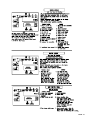
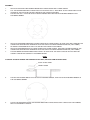
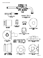
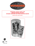
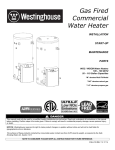
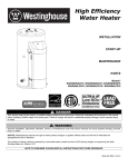
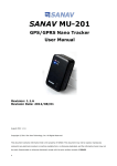
OPERATING, INSTALLATION, AND
SERVICE MANUAL FOR THE
VOYAGER GAS FIRED WATER HEATER
SUPER HIGH EFFICIENCY GAS FIRED WATER HEATING COMBINATION APPLIANCE
member
gama
ANSI Z 21.10.3
MANUFACTURED BY:
Visit our website at: WWW.HTPRODUCTS.COM
© 2008, 2006, 2005, 2004 Heat Transfer Products, Inc.
PAGE: 1
LP-41 REV: 9/26/08
TO REFERENCE VOYAGER MODEL NUMBERS, PLEASE
USE THE FOLLOWING GUIDELINES:
SSV
130
Series
BTU
- 45
S
U.S.
Gal.
A
Temperature
(Degrees Fahrenheit)
R = 160
S = 180
LP
Temp. Warr.
(Deg. F.)
Gas Type
Warranty
A = 6 yrs. parts; 6 yrs. comm.; 10 yrs. res.
B = 1 yr. parts; 3 yrs. comm.; 10 yrs. res.
SPECIFICATIONS
MODEL
INPUT
GALLON
BTU/HR
CAPACITY NATURAL &
LP GAS
SSV199-119R
119
199,000
SSV199-80R
80
199,000
SSVH199-80R
80
199,000
SSV160-119R
119
160,000
SSV160-80R
80
160,000
SSV130-119R
119
130,000
SSV130-80R
80
130,000
TEMPERATURE RISE IN DEGREES FAHRENHEIT
40
50
60
70
80
90
100
110
120
130
140
GPH
545
436
363
311
272
242
218
198
181
167
155
GPM
9
7
6
5
4.5
4
3.5
3.3
3
2.7
2.5
GPH
545
436
363
311
272
242
218
198
181
167
155
GPM
9
7
6
5
4.5
4
3.5
3.3
3
2.7
2.5
GPH
545
436
363
311
272
242
218
198
181
167
155
GPM
9
7
6
5
4.5
4
3.5
3.3
3
2.7
2.5
GPH
436
349
290
249
218
193
174
158
145
134
124
GPM
7
5.8
4.8
4
3.6
3.2
2.9
2.6
2.4
2.2
2
GPH
436
349
290
249
218
193
174
158
145
134
124
GPM
7
5.8
4.8
4
3.6
3.2
2.9
2.6
2.4
2.2
2
GPH
354
283
236
202
177
157
141
128
118
109
101
GPM
5.9
4.7
3.9
3.9
2.9
2.6
2.3
2.1
1.9
1.8
1.6
GPH
354
283
236
202
177
157
141
128
118
109
101
GPM
5.9
4.7
3.9
3.9
2.9
2.6
2.3
2.1
1.9
1.8
1.6
Recovery on rating plate is based at 94% thermal efficiency at 100 degrees Fahrenheit rise, as required by A.N.S.I.
MODEL
HEIGHT
WIDTH
SHIP
WEIGHT
DEPTH
MODEL
INPUT
FIRST
HOUR
RATING
VENT
SIZE
RECOVERY
EFFIC. %
SSV199-119R
74"
27-1-4"
405 LBS.
36"
SSV199-119R
199,000
335
3"
94%
SSV199-80R
72"
23-1-4"
235 LBS.
32"
SSV199-80R
199,000
300
3"
94%
SSV160-119R
74"
27-1-4"
405 LBS.
36"
SSV160-119R
160,000
270
3"
94%
SSV160-80R
72"
23-1-4"
235 LBS.
32"
SSV160-80R
160,000
250
3"
94%
SSV130-119R
74"
27-1-4"
405 LBS.
36"
SSV130-119R
130,000
250
2"
94%
SSV130-80R
72"
23-1-4"
235 LBS.
32"
SSV130-80R
130,000
220
2"
94%
CONNECTION SIZES ARE 1 1/2" NPT DOMESTIC INLET, DOMESTIC OUTLET FOR THE 80 & 119 GALLON UNITS.
Note: These overall dimensions are approximate within +/– 1".
Heat Transfer Products reserves the right to change specifications or discontinue models without notice.
PAGE: 2
n WARNING
THE INFORMATION IN THESE INSTRUCTIONS MUST BE FOLLOWED EXACTLY, A FIRE OR
EXPLOSION WILL RESULT, CAUSING PROPERTY DAMAGE, PERSONAL INJURY, OR DEATH.
-
Do not store or use gasoline or other flammable vapors and liquids in the vicinity of this or any other appliance;
WHAT TO DO IF YOU SMELL GAS:
-
Do not try to light any appliance;
Do not touch any electrical switch; do not use any phone in your building;
Immediately call your gas supplier from a neighbor's phone;
Follow the gas supplier's instructions;
If you cannot reach your gas supplier; call the fire department;
Installation and service must be performed by a qualified installer, service agency or the gas supplier.
n DANGER
Water temperature over 125 degrees F. can cause severe burns instantly,
or death from scalds. Children, disabled, and elderly are at highest risk
of being scalded. See instruction manual before setting temperature at
water heater. Feel water before bathing or showering! Temperature
limiting valves are available.
LOCATION
Choose a location for your water heater centralized to the piping system, along with consideration to vent pipe length. As the length of
vent pipe increases the firing rate of the appliance decreases. You must also locate the Voyager where it will not be exposed to freezing temperatures. Additionally, you will need to place the water heater so that the controls, drain, inlet/outlet, and gas valve are easily
accessed. This appliance must not be installed outdoors, as it is certified as an indoor appliance, and must be kept vertical and on a
level surface. Also, care must be exercised when choosing the location of this appliance; where leakage from the relief valve, leakage
from related piping, or leakage from the tank or connections, will not result in damage to the surrounding areas or to the lower floors of
the building. A water heater should always be located in a area with a floor drain or installed in a drain pan suitable for water
heaters. Proper clearance must be provided around the Voyager as follows: Sides, bottom, top, and back are 0" (zero clearance).
Front of the appliance needs 24" service clearance minimum. This front service may be achieved by a non-rated or combustible door
or access panel; providing the 24" service clearance is achieved when the door is opened or panel is removed. Under no circumstances, shall Heat Transfer Products Inc. be held liable for any such water damage whatsoever. This water heater must not
be located near flammable liquids such as gasoline, adhesives, solvents, paint thinners, butane, liquefied propane, etc.; as
the controls of this appliance could ignite those vapors, causing an explosion.
TEMPERATURE AND PRESSURE RELIEF VALVE
A temperature and pressure relief valve is installed into the marked port (upper right), we recommend a WATTS 100XL-4 valve or
equivalent for 100,000 BTU models or below input, 40XL5 valve or equivalent for 130,000 BTU models or above input, meeting the
requirements for relief valves for hot water heaters as per ANSI Z21.22B-1984 by a nationally recognized lab that maintains a periodic
inspection of production of such listed safety device. The pressure rating of the valve must not exceed the listed working pressure of
this appliance, and must be rated to the proper BTU/hr capacity of the water heater. Do not, under any circumstances, thread a cap
or plug into the relief valve! Explosion, serious injury or death may result! Relief valve piping must be directed to the floor or to
an open drain, but not connected directly. There must be a 6" space between the outlet of relief valve piping and drain or floor. Do not
hook up to drain system directly without an air space. The relief valve must be periodically checked for proper operation.
EXPANSION TANK
A potable hot water expansion tank may be required to offset the water expansion as the water is heated. In most city plumbing systems, the water meter has a no return or back flow device built into the system to prevent back flowing of water back into city mains.
Some require back flow preventers on all incoming water supplies. Under these circumstances, you will need a hot water expansion
tank listed for potable water use. The expansion tank should be located on the cold inlet piping close to the water heater.
n CAUTION
The expansion tank must be suitable for hot potable water. Serious injury could result
PAGE: 3
DOMESTIC WATER CONNECTION
n CAUTION
NEVER USE DIELECTRIC UNIONS OR GALVANIZED STEEL FITTINGS ON ANY DOMESTIC WATER
CONNECTIONS. USE ONLY COPPER OR BRASS FITTINGS. TEFLON THREAD SEALANT MUST BE
USED ON ALL CONNECTIONS.
The domestic water connections must be installed in accordance to all local and national plumbing codes, or any applicable standard
which prevails. The inlet and outlet ports of the Voyager are 1" on 45 gallon models. On the 80 and 119 gallon models, the inlet and
outlet ports are 1 ½". On the cold inlet, (bottom left), install a 1" brass tee on 45 gallon models, or a 1 ½" tee on 80 and 119 gallon
models. On the run of the 1" brass tee, install with pipe sealant compound, a 1" brass drain cock or equivalent. Into the branch of the
1" or a 1 ½" brass tee, install a copper male adapter to match your copper plumbing system. For convenience, you may install a sweat
shut off valve and a union in the cold inlet piping to ease servicing in the future. If there is a back flow preventer, or any type of a no
return valve in the system, then you must install an additional tee here for a suitable potable hot water expansion tank. In the hot outlet, (top left), install a suitable adapter to match the copper tubing of the plumbing system. A thermal trap or heat trap loop may be
installed here, to provide additional energy savings and prevent the thermal siphoning of domestic hot water. Refer to pages 22 to 26
for typical installations.
NEW LOW WATER CUT-OFF
NORMAL OPERATION
A low water cut-off switch has been added to the High Efficiency Water Heater to stop the possibility of dry firing the water heater and
damaging the internal heat exchanger. The low water cut-off switch will be activated when the water heater is completely filled and the
LED light becomes illuminated on the ECO/Vent Switch located on the front of the water heater.
FAULT CONDITIONS
STEP 1: Check for low water condition in tank.
If the water heater is not completely filled, the low water switch will not activate the water heater. During a low water fault, the control
board three digit LED display will show LOC and the ECO/Vent Switch LED light will begin to flash. It could take as long as 5 minutes
before the water heater will physically lock out during the water heater operation.
Remedy: Low water condition in tank.
Turn off the electric supply, make sure that the cold water supply is turned on and the water heater is completely filled with water.
Verify this by opening a hot water faucet, allowing the water to flow until all the air is removed and clear water is present. Turn the electric supply back on and manually reset the control.
STEP 2:
If the ECO/Vent Switch LED light is still flashing after step 1, check the low water cut-off switch for possible damage.
Remedy: Low water cut-off switch damage.
Make sure the low water cut-off is operating correctly by checking the voltage with an electric meter. You should see 24 volts AC
across the red and black lead of the connector from the wire harness. If the electric meter reads 24 volts indicating there is power to
the switch, the next step is to put a jumper across the two green leads of the connector. If the ECO/Vent Switch LED illuminates and
the water temperature LED is on, then the low water cut-off switch needs to be replaced.
n WARNING
DO NOT ALLOW THE WATER HEATER TO OPERATE WITH THE JUMPER IN PLACE IN THE LOW
WATER CUT OFF CIRCUIT. PERMANENT DAMAGE TO THE HEAT EXCHANGER COULD RESULT AND
WARRANTY WILL BE VOID.
STEP 3:
If the ECO/Vent Switch LED light is still flashing check the low water cut-off wire harness for possible damage or disconnected.
Remedy: Low water cut-off wire harness damage or disconnected.
Make sure that all the wire connections are connected properly, reference the water heater control diagrams in the Installation Manual
on page 18 and 19, make sure that the wire harness is not damaged. If the wire harness is damaged, replace the wiring harness (Part
Number 7000-857).
After completing steps 1 through 3 and the ECO/Vent Switch LED light is still flashing it will be required to trouble shoot the ECO switch
(see page 16 in the Installation Manual).
PAGE: 4
n WARNING
A domestic hot water tempering/anti-scald valve must be installed into the hot water line to
prevent the maximum outlet water temperature from exceeding 119 degrees F. as per the national
standard plumbing code. Failure to do so will result in serious injury or death.
ELECTRICAL CONNECTION
The electrical connection for the Voyager is on the left side of the combustion shroud. There is a 1/2" knockout location for electrical
connection. All electrical wiring must be performed by a qualified licensed electrician, and in accordance with National Electrical Code,
or to the applicable local codes and standards. The electrical requirements are for standard 120 volts, 60 Hz 10 amp service. It is recommended that an electrical disconnect switch be placed on a nearby wall, and that the connection to the Voyager be made using 3/8"
extra-flex, or 3/8" greenfield (or equivalent). This unit must be wired with #14 awg, and fused for no more than 15 amps.
n WARNING
This unit must be properly grounded! Follow instructions below. Failure to do so will result in
serious injury or death.
Ground the water heater, by connecting the green wire in the electrical access compartment, directly to the main building ground system. It is very important that the building system ground is inspected by a qualified electrician, prior to making this connection. The
black wire is the hot lead and the white wire is the neutral lead. Once all connections have been made the electrical access may be
closed. It is very important that the electrical power is not turned on at this time! A green LED is provided on the main control board.
This LED must be luminated when appliance is turned on for proper operation. Failure to luminate means bad or missing ground or
reverse polarity.
GAS CONNECTION
Gas supply shall have a maximum inlet pressure of less than 14" water column (350 mm), 1/2 pound pressure (3.4 kPa), and a minimum of 7" water column. The entire piping system, gas meter, and regulator must be sized properly to prevent pressure drop greater
than 0.5" as stated in the National Fuel Gas Code. This information is listed on the rating plate.
n WARNING
You must be connected to the type of gas as noted on the rating plate. You must ensure that the
entire gas line to the connection at the Voyager is no smaller than 3/4". In the event the gas valve is
exposed to a pressure greater than 1/2 PSI, 14" water column, the gas valve must be replaced.
Failure to follow all precautions below could result in fire, explosion or death.
"LP" or liquefied petroleum, or propane gas; or "Nat" natural gas or city gas. All gas connections must be approved by the local gas
supplier, or utility in addition to the governing authority, prior to turning the gas supply on. The nipple provided is 1/2", and it is mandatory that a 3/4" to 1/2" reducing bushing (provided) is used, threaded into the branch of a 3/4" tee and a drip leg fabricated, as per the
national Fuel Gas Code. Once all the inspections have been performed, the piping must be leak tested. If the leak test requirement is
a higher test pressure than the maximum inlet pressure, you must isolate the Voyager from the gas line. In order to do this, you must
disconnect the union and cap the inlet gas line.
n DANGER
Never use an open flame (lit match, lighter) to check gas connections.
Failure to do so will result in serious injury or death.
It is recommended that a soapy solution be used to detect leaks. Bubbles will appear on pipe to indicate a leak is present. The gas
piping must be sized for the proper flow and length of pipe, to avoid pressure drop. Both the gas meter and the gas regulator must be
properly sized for the total gas load. If you experience a pressure drop greater than 1" WC, the meter or regulator or gas line is undersized or in need of service. On the inlet side of the gas valve, there is a 1/8" NPT plug, which can be removed to attach a hose barb,
hose, and inches of water column meter. Also, you can attach a meter to the incoming gas drip leg, by removing the cap and installing
the meter. The gas pressure must remain between 7" and 14" during stand-by and unit running heat cycle. If an in-line regulator is
used, it must be a minimum of 10 feet from the Voyager. It is very important that the gas line is properly purged by the gas supplier or utility. Failure to properly purge the lines or improper line sizing, will result in the failure of the Voyager lighting off.
This problem is especially noticeable in NEW LP installations, and also in empty tank situations. This can also occur when a utility
company shuts off service to an area to provide maintenance to their lines.
PAGE: 5
n WARNING
THE GAS VALVE MUST NOT BE REPLACED WITH A CONVENTIONAL VALVE UNDER ANY
CIRCUMSTANCES. MAKE SURE GAS VALVE IS IN THE “OFF” POSITION PRIOR TO TURNING THE
GAS SUPPLY ON.
GAS VALVE
The Gas Valve is a special valve which has a pressure Augmented Regulator Feature, as well as negative outlet pressure. As an additional safety feature , this valve has a left hand thread on the outlet end and a special tamper resistant electrical connector.
VENTING
For inlet air supply, top pipe on the right of the shroud, use 3" PVC schedule 40. It is very important that you plan the location properly,
to eliminate long pipe runs and excessive fittings. Inlet pipe size must not be reduced. Do not combine the inlet air with any other inlet
pipe including an inlet to an additional similar appliance. The joints must be properly cleaned, primed, and cemented. The piping must
also be properly supported as per local and national standard plumbing codes. It is important that the piping must be clean and free
from burrs, debris, ragged ends, and particles of PVC.
For exhaust piping, lower pipe on the right of the shroud, for the first 7’, use 3” ABS sch 40 or 3”CPVC sch 40 or 80. For concrete construction or to meet certain fire codes, exhaust piping - lower pipe on right of shroud, and inlet air piping - top pipe on the right of the
shroud, must be 3" CPVC schedule 40 or 80, (only to meet local fire codes). The balance of the inlet and exhaust piping may be PVC
schedule 40 or 80, or ABS solid only, NOT FOAM CORE. For residential style wooden construction exhaust piping, lower pipe on right
of shroud, must be 3" ABS solid (NON FOAM CORE) or 3" CPVC schedule 40 or 80 for the first 7’ only. The balance of the inlet and
exhaust piping may be PVC or ABS solid NON FOAM CORE or CPVC to meet local codes.
The only approved exhaust vent materials are ABS solid NON FOAM CORE; first 84" or CPVC. The balance of the exhaust piping
must be ABS solid NON FOAM CORE, CPVC or PVC sch 40 NON FOAM CORE ONLY. Exhaust piping should be sloped back to the
connection on the Voyager, at least 1/4" per foot to remove additional condensate that forms within the pipe. The total combined
length of pipe (intake piping plus exhaust piping added together) including elbow allowances intake and exhaust (each elbow = 5' of
pipe) should not exceed 85'. The combined vent length should not be less than a combined length of 6' plus two 90 degree elbows.
Choose your vent termination locations carefully; see pages 22 and 23. You must additionally make certain that exhaust gas does not
re-circulate back into the intake pipe. You must place them in a open area, and follow the following guidelines.
NOTE: Per requirement of the ANSI Z21.10.3. 2004 1 CSA 4.3 -2004 a thorough review and compliance to Fig. 3-A pg. 21 in this
manual is required.
n WARNING
1)
Never vent into a walkway or patio area, or an alley, or otherwise public area less than 7' from
the ground;
2) Never vent over or under a window or over a doorway;
3) Never install a heat saver or similar product to capture waste heat from exhaust;
4) Always have vent location at least 1' above maximum snow level;
5) Always have vent 1' above ground level, away from shrubs and bushes;
6) Follow local gas codes in your region or refer to National Fuel Gas Code, or Can B149;
7) Always have vent at least 3' from an inside corner of outside walls;
8) Maintain clearance to electric, gas meters, and exhaust fans or inlets; (See Fig. 3A pg. 21 for
clearances)
9) Very Important! Inlet air must be taken from outside of building, next to exhaust outlet, no
closer than 8";
10) Always place screens in all openings in intake and exhaust to prevent foreign matter from
entering the Voyager.
11)
The vent intake and exhaust must be properly cleaned and glued, for pressure tight joints. Several methods for venting the
Voyager can be found on pages 22 and 23. Use the following layout as a guideline; certain site conditions such as multiple
roof lines/pitches may require venting modifications-consult factory. The air inlet must be a minimum of 1' vertically above the
maximum snow level or 24" which ever is greater. The air inlet must also be a minimum of 10' horizontally from the roof, and
terminated with a tee. The exhaust must be a minimum of 24" above the air inlet opening, and terminated with a coupling. It
is very important that there are no other vents, chimneys or air inlets in any direction for at least 4'. All venting must be properly supported, as the Voyager is not intended to support any venting whatsoever. All piping, glue, solvents, cleaners,
fittings, and components, must conform to ASTM (American Society for Testing and Materials), and ANSI (American National
Standard Institute).
PAGE: 6
n WARNING
You must not connect vent connectors serving other appliances vented by natural draft into
any portion of mechanical draft systems operating under positive pressure.
Follow the venting instructions below carefully. Failure to do so may result in severe
personal injury, death, or substantial property damage.
1.
Install the water heater venting system in accordance with these instructions and with the National Fuel Gas Code, ANSI
Z223.1/NFPA 54, CAN/CGA B149, and/or applicable provisions of local building codes.
2.
This water heater is a direct vent appliance and is listed as a Category IV appliance with Underwriters Laboratories, Inc. VENT
AND INTAKE AIR VENT
APPROVED MATERIALS FOR EXHAUST VENT AND INTAKE AIR VENT
PIPE / FITTINGS
APPROVED VENTING MATERIAL
Item
Vent or air pipe
and fittings
Pipe
cement/primer
Material
Standards for Installation in:
United States
PVC schedule 40/80
ANSI/ASTM D1785
PVC-DWV
ANSI/ASTM D2665
CPVC schedule 40/80
ANSI/ASTM F441
PVC
ANSI/ASTM D2564
CPVC
ANSI/ASTM F493
Canada
CPVC and PVC venting must be ULC-S636 Certified.
IPEX is an approved manufacturer in Canada supplying
vent material listed to ULC-S636
IPEX System 636
Cements & Primers
n WARNING
Do not use Foam Core Pipe in any portion of the exhaust piping from this water heater. Use of
Foam Core Pipe may result in severe personal injury, death, or substantial property damage.
FOR LONGER VENT LENGTHS
All venting must be 3", both intake and exhaust, NEVER use any piping less than 3", or different size pipe on the intake and
exhaust. You may use 4" venting on both intake and exhaust, to lower the pressure drop, to provide additional venting length. It is
imperative when using 4", to follow these instructions very carefully. For longer venting lengths, the first 10' of both the
intake and exhaust piping are 3". For the intake 10' of 3" PVC plus one 90 degree or two 45 degree elbows and for the
exhaust 10' of ABS solid NON FOAM CORE, or CPVC plus one 90 degree or two 45 degree elbows. Then use a 4" x 3" PVC or
4" x 3" ABS reducing coupling. Then proceed with PVC 4" NON FOAM CORE pipe and fittings for both the intake and exhaust piping.
On 4" piping you may go an additional 125 equivalent feet of pipe and fittings, combined total length. The 4" fittings have a friction loss
allowance as follows: 4" 90 degree = 3' , and a 4" 45 degree = 1'. The total maximum venting length can be 125', plus the first
10' of each 3", and a maximum fitting allowance of the 3", total two 90 degree or four 45 degree before increasing to 4". Total
equivalent would be 30' of 3" plus 125' of 4".
n WARNING
All vent piping must be properly supported. Do not use unit for support.
n WARNING
Never use different pipe sizes for intake and exhaust. The vent system must be balanced by friction
loss equivalent.
NOTE:
THE METHODS DESCRIBED ARE SUGGESTED GENERIC METHODS ONLY. SPECIFIC JOB SITE OBSERVATIONS AND SIZING MAY REQUIRE ALTERNATE INSTALLATION METHODS. CONSULT THE FACTORY WITH SPECIFIC JOB REQUIREMENTS FOR ADDITIONAL RECOMMENDATIONS.
PAGE: 7
FRICTION LOSS EQUIVALENCE TABLES
2" VENTED MODELS
SSV100-45R/SSV130-45R
3" VENTED MODELS
FITTING
DESC.
EQUIVALENT
FEET
OF PIPE
3” 90
3” 45
3” Coupling
3” Tee
3” Pipe
3” Concentric vent kit
3” V1000 vent kit
5’
3’
0’
0’
1’ = 1’
3’
0’
FITTING DESC.
EQUIVALENT
FEET
OF PIPE
2” 90
2” 45
2” Coupling
2” Tee
2” Pipe
2” Concentric vent kit
5’
3’
0’
0’
1’ = 1’
3’
AFTER THE FIRST 10’ OF 3"
ONLY4" EQUIVALENT TABLE
FITTING DESC.
4” 90
4” 45
4” Coupling
4” Pipe
4” Tee
EQUIVALENT
FEET OF
PIPE
3’
1’
0’
1’ = 1’
0’
VENTING EXAMPLES (NOTE:
SHOWN AS INTAKE & EXHAUST PIPE AND FITTINGS ADDED TOGETHER)
* = MINIMUM VENT LENGTH
** = MAXIMUM VENT LENGTH
TOTAL
COMBINED
VENT LENGTH
(FEET)
INTAKE &
EXHAUST
*12
20
20
20
20
20
20
20
20
20
20
20
20**
30
30
30
30
30
30
30
30
30**
40
40
40
40
40
40
40**
50
50
50
50
50**
60
60
60**
70**
QTY.
OF 90°
ELBOWS
2
2
3
4
5
6
7
8
9
10
11
12
13
3
4
5
6
7
8
9
10
11
3
4
5
6
7
8
9
3
4
5
6
7
3
4
5
3
EQUIVALENT
FRICTION
LOSS
(FEET)
FOR EACH
ELBOW
5
5
5
5
5
5
5
5
5
5
5
5
5
5
5
5
5
5
5
5
5
5
5
5
5
5
5
5
5
5
5
5
5
5
5
5
5
5
TOTAL
FRICTION
LOSS
FOR
ELBOWS
10
10
15
20
25
30
35
40
45
50
55
60
65
15
20
25
30
35
40
45
50
55
15
20
25
30
35
40
45
15
20
25
30
35
15
20
25
15
GRAND TOTAL
VENT LENGTH
(FEET)
WITH FITTING
FRICTION
LOSS ADDED
22
30
35
40
45
50
55
60
65
70
75
80
85**
45
50
55
60
65
70
75
80
85**
55
60
65
70
75
80
85**
65
70
75
80
85**
75
80
85
85
PAGE: 8
WARNING
YOU MUST FOLLOW THESE CONDENSATE INSTRUCTIONS EXACTLY. FAILURE TO FOLLOW
INSTRUCTIONS EXACTLY COULD RESULT IN FIRE, INJURY OR DEATH.
CONDENSATE
This is a condensing high efficiency appliance, therefore this unit has a condensate removal system. Condensate is nothing more than
water vapor, derived from the combustion products, similar to an automobile when it is initially started. This condensate does have a
low PH and should be treated with a condensate filter. This filter contains either lime crystals or marble crystals, which will neutralize
the condensate. The outlet of the filter is sized for 5/8" ID (Inside diameter) plastic tubing. It is very important that the condensate line
is sloped away from and down to a suitable inside drain, if the condensate outlet on the Voyager is lower than the drain, you must use
a condensate removal pump. A condensate filter and a condensate pump kit are available from HTP. It is also very important that the
condensate line is not exposed to freezing temperatures, or any other type of blockage. Plastic tubing should be the only material used
for the condensate line; as steel, brass, copper, or others will be subject to corrosion and deterioration. A second vent may be necessary to prevent condensate line vacuum lock if a long horizontal run is used. Also an increase to 1" tubing may be necessary, (See the
diagram on page 25).
CONTROL DESCRIPTION
The fully integrated water heater control is an all electronic with a fully automatic controller that will provide many years of trouble free
service. The control requires no periodic maintenance and includes a built-in microprocessor which performs a number of diagnostic
tests to verify proper appliance and control operation. Should an unsafe condition occur, the burner will shut down and the appropriate
status indicators will illuminate indicating the need for service. Consisting of two printed circuit board assemblies, the controller's main
board is attached to inside left of the shroud while the display board is mounted to the front top of the shroud. This arrangement simplifies access to the user adjustments while enhancing the visibility of the temperature display and status indicators. A power step-down
transformer and blower pressure switch are also mounted on the inside left of the shroud. The controller display functions include a
high visibility three digit LED readout which is used to display the actual water temperature within the tank along with the programmed
desired water temperature (set point temperature). Nine individual LED indicators are also mounted on the display board which are
used to determine the operating status of the appliance and provide assistance when troubleshooting any problems which may occur.
All indicators are of the solid state variety and should last for the life of the appliance. The controller has sufficient built-in memory to
retain the programmed temperature set point in the event input power is ever interrupted. The final component of the control system
includes a temperature sensing probe which is threaded into the side of the tank. This probe is of unique construction in that both the
temperature sensing/control and safety limit functions are performed by this single device. All probe components are of solid state construction to provide extended operational life.
START UP PROCEDURE
1.
2.
3.
4.
5.
Make sure that the Voyager has been installed to these instruction procedures; along with all applicable province and local
codes;
Make sure all gas piping and connections have been verified and inspected by all applicable inspectors. Turn on gas supply.
Insure that the gas line and the LP tank, if applicable, have been properly purged. Failure to properly purge the gas lines will
result in failure to operate;
Make sure that the cold water supply has been turned on and that the Voyager is completely filled with water. Verify this by
opening a hot water faucet, and allowing water to flow until all air is removed and a clear water flow is present;
Turn on electrical supply;
The control will first display "102", then "88.8", which is the control display test; and finally the actual tank temperature at the
probe.
SET POINT ADJUSTMENT PROCEDURE
The three digit LED display will illustrate actual water temperature within the tank under normal operating conditions. However, this
display is also used to indicate the temperature set point when in the programming mode; and also ignitor amp draw and flame current.
The controller has a temperature set point range 70 degrees F. to 160 degrees F. The factory set point is 118 degrees F.
n DANGER
Water temperature over 125 degrees F. can cause severe burns instantly,
or death from scalds. Children, disabled, and elderly are at highest risk
of being scalded. See instruction manual before setting temperature at
water heater. Feel water before bathing or showering! Temperature
limiting valves are available.
PAGE: 9
VERY IMPORTANT NOTE:
POWER MUST BE APPLIED TO THE CONTROLLER PRIOR TO ANY PROGRAMMING OPERATIONS.
SET POINT ADJUSTMENT PROCEDURE (CONTINUED)
To change or access the programmed temperature set point value, utilize the red button on the display panel. Momentarily depressing
the button will briefly illustrate the existing set point value. If the button is held down for more than one second, the programming mode
is entered and the set point value will begin incrementing by one degree per second. When the desired set point value is reached, simply release the button and the controller will automatically retain this value in temporary memory. After 30 seconds, this new set point
will be retained in permanent memory.
NOTE:
IF POWER IS INTERRUPTED DURING THIS 30 SECOND PERIOD, THE NEW SET POINT WILL NOT BE RETAINED IN PERMANENT MEMORY. IT IS A GOOD PRACTICE TO RE-CHECK THE SET POINT VALUE APPROXIMATELY 60 SECONDS AFTER A
NEW VALUE HAS BEEN RE-ENTERED.
If the button is held down long enough, the set point will reach 160 degrees F. and stop, since this is its maximum value. At this point,
if the desired set point has not been obtained, release the button and depress it again, the set point will decrement down to 70 degrees
F. and stop. The set point value will now restart at 70 degrees F. (its minimum) and once again increase in value for as long as the
button is pressed.
DIFFERENTIAL ADJUSTMENT PROCEDURE
To allow proper water heater operation, the control has a 8 degree F. "window" around the set point. This means that the burner will
be turned on when the water temperature drops to 4 degrees F. below the set point, and it will be turned off when the water temperature reaches 4 degrees F above the set point. Thus, if the set point is set to 120 degrees F., the control will turn on the burner when
the water temperature drops to 116 degrees F., and will continue to heat the water until the temperature reaches 124 degrees F. The
differential is factory set to 8 degrees F. (+ or- 4 degrees F.) If another differential is required, the value of the differential can be field
adjusted by holding the set point button when power is applied to the control. Shut off power to the control. Next hold in the set point
button. Now reapply power to the control. Using the set point button, the value of the differential can be incremented or decremented
as above. When the proper value is reached, release the button and the new differential has been stored into permanent memory.
OVERALL APPLIANCE AND CONTROL OPERATION
A normal operating sequence is as follows:
1.
2.
3.
4.
5.
6.
7.
8.
9.
10.
The control determines that the actual water temperature inside tank is 4 degrees F., with the factory set 8 degree F.
differential, below programmed temperature set point;
The control performs selected system diagnostic checks;
If all checks are successfully passed, the combustion blower is energized for the 40 second pre-purge cycle;
During the pre-purge cycle is complete, power is applied to the ignitor element for the ignitor warm-up period (blower should
continue to run);
The ignitor warm-up period will last for 30 seconds, then gas valve will be opened, allowing gas to enter the burner chamber;
The ignitor will remain on for an additional 4 seconds, then it will be turned off;
After an additional 2 seconds, the control will verify the presence of flame. If the flame was not established, the gas valve will
be closed, power will be removed from the ignitor element, and the control will run the blower for 30 seconds. At this point,
the control will return to step 2;
If flame is present, the control will enter the heating mode where it will continue heating the tank water until the set point
temperature plus 4 degrees F. is reached. At this point, the gas valve is closed and the control enters the post-purge cycle.
The flame can be viewed through a window on the lower right of combustion blower flange;
The post-purge cycle continues to run the combustion blower for an additional 30 seconds to purge the system of all
combustion gases. After this time period, the blower is de-energized and will coast to a stop;
The control will now enter the idle state while continuing to monitor internal tank water temperature. If the temperature drops
to 4 degrees F. below the set point value, the control will automatically return to step 1.
STATUS INDICATORS
Pages 15, 16, and 17 contain seven individual diagrams which illustrate the various operating states of the appliance and their relation
to the LED status indicators found on the controller. These diagrams reflect normal water heater operation.
MAINTENANCE
The control system requires no periodic maintenance under normal conditions. However, in unusually dirty or dusty conditions, periodic vacuuming of the cover to maintain visibility of the display and indicators is recommended. In dirty environments, construction sites,
building constructions, care must be taken to keep the appliance door in place and drywall or saw dust away from appliance.
PAGE: 10
n CAUTION
In unusually dirty or dusty conditions, care must be taken to keep appliance door in place. Failure to
do so VOIDS WARRANTY!
INTERNAL WIRING
For specific wiring information, please refer to the diagrams on pages 18 and 19.
SHUTDOWN PROCEDURE
If the burner is operating, lower the set point value to 70 degrees F. and wait for the burner to shut off. Continue to wait for the combustion blower to stop so all latent combustion gases are purged from the system. This should take a maximum of 40 to 90 seconds.
Disconnect the electrical supply. If the burner is not operating, disconnect the electrical supply.
VACATION PROCEDURE
If there is danger of freezing, change the set point to 70 degrees F. DO NOT turn off electrical power. If there is no danger of
freezing, follow the "Shutdown Procedure".
FAILURE TO OPERATE
Should the burner fail to light, the control will perform two more ignition trials prior to entering a lockout state (“LOC”). Note that each
subsequent ignition trial will not occur immediately. After a failed ignition trial, the blower must run for approximately 10 seconds to
purge the system, then the ignitor element must complete a 30 second warm-up period. Therefore, a time period of approximately 40
to 90 seconds will expire between each ignition trial. If the burner lights during any one of these three ignition trails, normal operation
will resume. If the burner lights, but goes off in about 4 seconds, check the polarity of the wiring. See electrical connection section on
page 4. If the burner does not light after the third ignition trial, the control will enter a lockout state. This lockout state indicates that a
problem exists with either the appliance, the controls, or the gas supply. Under such circumstances, a qualified service technician
should be contacted immediately to properly service the appliance and correct the problem. If a technician is not available, depressing
the red button once will remove the lockout state so additional trials for ignition can be performed. Any time “LOC” is shown, you
must look for an LED out, or flashing. The LED that is out or flashing will assist you in diagnosing lock out condition.
PAGE: 11
PAGE: 12
REPLACEMENT PARTS NOT SHOWN
LOW VOLTAGE CABLE ASSEMBLY
(710B0041)
INTERCONNECT RIBBON CABLE
(7000-665)
LINE CABLE
(710B0048)
PUSH BUTTON
(7000-667)
TRANSFORMER
(7000-666)
GASKET BURNER MOUNTING FLANGE
(G5010)
GASKET BLOWER OUTLET FLANGE
(G5020)
GASKET AIR INLET
(G5030)
GASKET BURNER MOUNTING FLANGE WHITE
(7000-815)
ORIFICES
All of the Voyager gas fired water heaters have unique air and gas orifice sizes. Special attention should be paid to these sizes whenever converting a heater from one fuel type to another, or when the orifice is changed for any reason. Below is a list of orifice sizes for
conversions to other fuel types and the sizes the voyager was shipped with from the factory. Please note that air orifices do not have
to be changed when switching from one fuel type to another. This information is not intended to allow field conversions by drilling orifices. This is only a guide to correct orifice sizing.
n WARNING
You must not drill orifices. The result will be poor ignition, explosion, severe bodily injury or death.
All orifices must be obtained through the factory with all necessary labels and the serial number must be provided to the factory OR
WARRANTY WILL BE VOIDED.
VOYAGER GAS CONVERSION INSTRUCTIONS
FOR CONVERSION OF THE VOYAGER TO PROPANE OR NATURAL GAS. YOU MUST ORDER A CONVERSION KIT FROM THE
FACTORY. BELOW IS A LIST OF THE DIFFERENT MODEL NUMBERS YOU WILL NEED TO REFERENCE WHEN ORDERING
YOUR KIT. PLEASE CALL THE FACTORY AT 1-800-323-9651, CUSTOMER SERVICE TO PLACE YOUR ORDER.
100,000
100,000
130,000
130,000
160,000
160,000
199,000
PROPANE TO NATURAL – (N10AG)
NATURAL TO PROPANE – (P10AG)
PROPANE TO NATURAL – (N13AG)
NATURAL TO PROPANE – (P13AG)
PROPANE TO NATURAL – (N16AG)
NATURAL TO PROPANE – (P16AG)
PROPANE TO NATURAL – (N19AG)
199,000 BTU VOYAGERSAIR ORIFICE = 1.375"
GAS ORIFICE SIZESNATURAL GAS = .379"
PROPANE/LP GAS =
.295"
160,000 BTU VOYAGERSAIR ORIFICE = 1.375"
GAS ORIFICE SIZESNATURAL GAS = .362"
PROPANE/LP GAS =
.295"
130,000 BTU VOYAGERSAIR ORIFICE = 1.125"
GAS ORIFICE SIZESNATURAL GAS = .280"
PROPANE/LP GAS =
.235"
NATURAL GAS CONVERSION FROM PROPANE/LP =
.285"
PROPANE/LP GAS CONVERSION FROM NATURAL GAS = .250"
CAUTION:
THERE ARE NO USER SERVICEABLE PARTS WITHIN THE CONTROL SYSTEM. TO MAINTAIN SAFETY AND PROPER APPLIANCE PERFORMANCE, REFER ALL TROUBLE-SHOOTING TO QUALIFIED SERVICE PERSONNEL.
PAGE: 13
TROUBLE-SHOOTING
The appliance controller has many inherent diagnostic and fault detection routines built into its operating software and hardware.
These routines, along with the three digit LED display and nine LED status indicators present on the display panel, can greatly assist
the service person in quickly pinpointing the source of problems that may occur with the appliance. In certain circumstances, multiple
LED's may be lit or flashing to better pinpoint the problem. Also, there is a green LED on the main control board to indicate proper
polarity and grounding. The following charts, diagrams, and information can be used during
troubleshooting procedures:
LED
CONTROLLER FUNCTION
MEANING
LINE
MONITORS INCOMING AC LINE VOLTAGE
“ON” WHEN LINE VOLTAGE IS PRESENT
BLOWER
MONITORS THE BLOWER MOTOR OUTPUT
“ON” WHEN OUTPUT IS ENERGIZED
(POWER APPLIED TO BLOWER)
IGNITOR
MONITORS IGNITOR ELEMENT OUTPUT
“ON” WHEN OUTPUT IS ENERGIZED
(POWER APPLIED TO IGNITOR)
24V
MONITORS INCOMING VOLTAGE FROM THE
TRANSFORMER SECONDARY
“ON” WHEN SECONDARY VOLTAGE IS PRESENT
ECO
MONITORS STATE OF THE ECO SWITCH
AND LOW WATER CUT-OFF
“ON” WHEN ECO SWITCH AND LOW WATER CUT-OFF
IS IN CLOSED POSITION (NORMAL POSITION)
PRESSURE
MONITORS STATE OF THE AIR SWITCH
“ON” WHEN THE PRESSURE SWITCH IS CLOSED
(SUFFICIENT COMBUSTION AIRFLOW EXISTS)
GAS VALVE
MONITORS THE GAS VALVE OUTPUT
“ON” WHEN OUTPUT IS ENERGIZED
(POWER APPLIED TO GAS VALVE)
WATER TEMP.
MONITORS WATER TEMP. WITHIN TANK
“ON” WHEN TEMP. DROPS BELOW SET POINT
CONTROL
HEALTH
MONITORS INTERNAL STATE OF THE
CONTROLLER’S HARDWARE AND SOFTWARE
“ON” WHEN CONTROLLER FUNCTIONALITY IS O.K.
GREEN ON
MONITORS POLARITY AND GROUND CIRCUIT
MAIN CONTROL
BOARD
“ON” WHEN GROUND AND POLARITY ARE O.K.
n WARNING
YOU MUST USE A COMBUSTION ANALYZER WHEN SETTING UP THE VOYAGER. ONLY AN HTP
APPROVED CONVERSION KIT SHOULD BE USED WHEN DOING A GAS CONVERSION.
COMBUSTION SETTINGS
HIGH FIRING RATES and LOW FIRING RATES ON ALL MODELS
Natural Gas
Carbon Monoxide
(CO%)
Carbon Dioxide
(CO2%)
Propane LP
low
high
low
high
0–10 ppm
0 ppm–20 ppm
0–10 ppm
0 ppm–20 ppm
8½% – 9½%
8½% – 9½%
9½% – 10½%
9½% – 10½%
PAGE: 14
PAGE: 15
PAGE: 16
PAGE: 17
PAGE: 18
PAGE: 19
TYPICAL VENTING
n CAUTION
ADDITIONAL PIPING CAN BE ABS OR PVC. ALL VENT PIPING MUST BE PROPERLY SUPPORTED.
THE APPLIANCE IS NOT INTENDED TO SUPPORT VENTING PIPES.
PLEASE NOTE: THE METHODS DESCRIBED ARE SUGGESTED GENERIC METHODS ONLY. SPECIFIC JOB SITE
OBSERVATIONS AND SIZING MAY REQUIRE ALTERNATE INSTALLATION METHODS.
REFER TO FIG. 3A PG. 21 FOR FURTHER DETAILS.
1)
Never vent into a walkway or patio area, or any alley, or otherwise public area less than 7’ from the ground.
2)
never install a heat saver or similar product to capture waste heat from exhaust.
3)
Always have a vent location at least 1’ above maximum snow level.
4)
Always have vent 1’ above ground level, away from shrubs and bushes.
5)
Always be at least 2’ horizontally from doors or windows. (36” for Canadian installations. Refer to Fig. 3A pg. 21.)
6)
Always have vent at least 3’ from inside corner of outside walls.
7)
Maintain at least 4’ clearance to electric, bas meters, and exhaust fans or inlets.
8)
VERY IMPORTANT!! Inlet air must be taken from outside of building, next to exhaust outlet, no closer than 8”.
9)
Always place screens in all the intake and exhaust openings to prevent foreign matter from entering the Voyager.
10) The vent intake and exhaust must be properly cleaned and glued for pressure tight joints.
11) The vent intake and exhaust must be properly cleaned and glued, for pressure tight joints. Several methods for
venting the Voyager can be found on pages 22 and 23. Use the following layout as a guideline; certain site
conditions such as multiple roof lines/pitches may require venting modifications – consult factory. The air inlet must
be a minimum of 1’ vertically above the maximum snow level of 24”, whichever is greater. The air inlet must also be a
minimum of 10’ horizontally from the roof, and terminated with a tee. The exhaust must be minimum of 24” above the
air inlet opening, and terminated with a coupling. It is very important that there are no other vents, chimneys, or air
inlets in any direction for at least 4’. Please refer to typical venting on pages 22 and 23. ALL VENTING MUST BE
PROPERLY SUPPORTED, AS THE VOYAGER IS NOT INTENDED TO SUPPORT ANY VENTING
WHATSOEVER. All piping, glue, solvents, cleaners, fittings, and components, must conform to ASTM (American
Society for Testing and Materials), and ANSI (American National Standard Institute).
12) It is recommended that you use one of the mentioned vent kits specifically for Voyager installations; either
KGAVT0501CVT (2 in.) or KGAVT0601CVT (3 in.) or the V1000.
NOTE: CLEARANCE SHALL BE IN ACCORDANCE WITH LOCAL INSTALLATION CODES AND TH REQUIREMENTS OF
THE GAS SUPPLIER.
PAGE: 20
Location of exit terminals of mechanical draft and direct-vent venting systems.
(Reference: National Fuel Gas Code ANSI Z223.1/NFPA 54 2002).
Multiple Vent Spacing*
*Note: Exhaust must extend out 1 foot. There should be no more than 2 vents and 2 intakes then a space of 36” to the
next set of vents.
*Note: There must be a minimum of 36” spacing between every 2 kit grouping.
Multiple Stainless Steel Horizontal Vent Kit Installation – Front View
PAGE: 21
PAGE: 22
PAGE: 23
PAGE: 24
PAGE: 25
COMPLETE TEAR DOWN PROCEDURE
TOOLS REQUIRED:
5/16" NUT DRIVER
3/8" DEEP SOCKET
7/16" DEEP SOCKET
½" DEEP SOCKET
3/8" WRENCH
7/16" WRENCH
¼" FLAT HEAD SCREWDRIVER
#2 PHILLIPS HEAD SCREWDRIVER
10" PIPE WRENCH
1 ¼" DRIVE INCH POUND TORQUE
WRENCH (RANGE 0-200)
SNAP RING OR NEEDLE NOSE PLIERS
NOTE:
SEE END OF THIS SECTION FOR PARTS DIAGRAMS.
1.
2.
3.
4.
5.
6.
7.
DISCONNECT POWER FROM UNIT.
SHUT OFF GAS SUPPLY.
REMOVE CABINET DOOR.
SHUT OFF GAS VALVE BY TURNING THE BLUE KNOB ON THE GAS VALVE.
DISCONNECT THE AIR INLET PIPE AT THE SMALL END OF THE AIR INLET CONNECTOR BY LOOSENING THE HOSE
CLAMP WITH A 5/16" NUT DRIVER.
REMOVE THE CLEAR VINYL HOSE THAT RUNS FROM THE GAS VALVE TO THE AIR INLET ADAPTER.
BREAK THE GAS ORIFICE UNION BY TURNING THE UNION CLOCKWISE WITH A 10" PIPE WRENCH.
NOTE:
BE SURE NOT TO LOSE THE GAS ORIFICE HELD INSIDE THE UNION.
8.
9.
REMOVE THE BRASS BARB FROM THE AIR INLET ADAPTER WITH A 7/16" DEEP SOCKET.
LOOSEN THE AIR INLET ADAPTER AND PULL THE AIR INLET ADAPTER THROUGH THE SIDE OF THE CABINET.
NOTE:
BE SURE NOT TO LOSE THE AIR ORIFICE SNAPPED INTO THE END OF THE ALUMINUM PIPE.
10.
11.
12.
13.
14.
15.
16.
17.
18.
19.
20.
21.
22.
23.
24.
25.
REMOVE THE FOUR BRASS NUTS HOLDING THE ALUMINUM AIR INLET ASSEMBLY TO THE BLOWER, WITH A 3/8"
DEEP SOCKET.
REMOVE THE BLOWER OUTLET FLANGE GASKET FROM THE BLOWER.
REMOVE THE GAS VALVE WIRING HARNESS FROM THE GAS VALVE BY PRESSING ON THE TABS ON THE TOP
AND BOTTOM OF THE PLUG AND PULLING.
REMOVE THE TWO GREEN GROUNDING WIRES FROM THE TOP/REAR OF THE BLOWER BY TAKING OUT THE
GREEN GROUNDING SCREW WITH A 5/16" NUT DRIVER.
REMOVE THE BLACK WIRE FROM THE FLAME RECTIFICATION PROBE, BY PULLING ON IT.
REMOVE THE IGNITOR WIRING HARNESS FROM THE CONTROL BOARD BY PRESSING ON THE TABS ON THE TOP
AND BOTTOM OF THE PLUG AND PULLING.
REMOVE THE TWO BRASS NUTS RETAINING THE IGNITOR, WITH A 3/8" DEEP SOCKET.
GENTLY PRY THE IGNITOR BACK ABOUT 1/16 OF AN INCH, WITH A ¼" FLAT HEAD SCREWDRIVER. NOW PULL
THE IGNITOR STRAIGHT BACK. BE VERY CAREFUL THAT YOU DO NOT WIGGLE THE IGNITOR AT ALL!
REMOVE THE FLAME RECTIFICATION PROBE BY REMOVING THE SCREW TO THE LEFT OF THE ELECTRICAL
CONNECTOR WITH A #2 PHILLIPS HEAD SCREWDRIVER AND PULLING IT STRAIGHT BACK.
REMOVE THE CLEAR VINYL HOSE FROM THE LEFT/BACK OF THE BLOWER.
REMOVE THE BLOWER WIRING HARNESS FROM THE LEFT/BOTTOM OF THE BLOWER BY PULLING STRAIGHT OUT.
REMOVE THE FOUR BRASS NUT RETAINING THE BLOWER TO THE OUTER BURNER MOUNTING FLANGE WITH A
7/16" WRENCH.
PULL THE BLOWER STRAIGHT BACK BEING CAREFUL NOT TO LOSE THE SIGHT GLASS.
REMOVE THE BURNER BY PRYING IT AWAY FROM THE OUTER BURNER MOUNTING FLANGE AND THEN PULLING
IT STRAIGHT BACK.
REMOVE THE OLD BURNER MOUNTING FLANGE GASKET BY REMOVING THE SIX NUTS WITH A ½" DEEP SOCKET.
REMOVE ALL OF THE OLD GASKET MATERIAL FROM ALL SURFACES EXCEPT FOR THE SIGHT GLASS WINDOW
GASKET.
PAGE: 26
ASSEMBLY
1.
2.
3.
4.
5.
6.
7.
REPLACE THE WHITE FIBER BURNER MOUNTING FLANGE GASKET WITH A NEW GASKET.
PUT THE BURNER MOUNTING FLANGE BACK IN PLACE WITH THE ½" HOLE NEXT TO THE LARGE HOLE IN THE
CENTER OF THE PLATE TO THE RIGHT AND WITH THE STUDS FACING OUT.
TIGHTEN THE SIX ½" NUTS TO 50 INCH POUNDS TORQUE AND THEN 200 INCH POUNDS TORQUE IN THE
FOLLOWING ORDER:
REPLACE THE BURNER MOUNTING FLANGE GASKET WITH A NEW GASKET, BE SURE THAT BOTH SIDES OF THE
GASKET ARE SPRAYED WITH PERMATEX HIGH TACK SPRAY-A-GASKET ADHESIVE SEALANT (PART #99MA).
RE-INSERT THE BURNER WITH THE FLAT SIDE OF THE FLANGE FACING DOWN.
REPLACE THE BLOWER OUTLET FLANGE GASKET WITH A NEW GASKET. BE SURE THAT BOTH SIDES OF THE
GASKET ARE SPRAYED WITH PERMATEX HIGH TACK SPRAY-A-GASKET ADHESIVE SEALANT (PART #99MA).
PLACE BLOWER ON BURNER MOUNTING FLANGE. BE SURE THAT THE SIGHT GLASS IS IN PLACE AND THE
GASKET IS INSTALLED CORRECTLY AS SHOWN BELOW:
NOTE:
IF GASKET OR SIGHT WINDOW ARE DAMAGED IN ANY WAY, REPLACE THEM WITH NEW ONES.
SIGHT GLASS G2000
GASKET G5060
8.
TIGHTEN THE BLOWER BOLTS FIRST TO 50 INCH POUNDS TORQUE, THEN TO 150 INCH POUNDS TORQUE, IN
THE FOLLOWING ORDER:
9.
PLACE THE IGNITOR BACK INTO THE BURNER MOUNTING FLANGE, BEING VERY CAREFUL OF THE ELEMENT,
WHICH IS EXTREMELY FRAGILE.
PAGE: 27
10.
11.
12.
13.
14.
TIGHTEN THE TWO 3/8" IGNITOR NUTS TO 50 INCH POUNDS TORQUE.
PLACE THE FLAME RECTIFICATION PROBE BACK INTO THE BURNER MOUNTING FLANGE AND TIGHTEN THE
SCREW WITH A #2 PHILLIPS HEAD SCREWDRIVER.
RE-INSTALL THE AIR INLET GASKET TO THE RIGHT SIDE OF THE BLOWER WITH THE TWO ANGLE CUTS FACING
TOWARD THE WATER HEATER.
RE-INSTALL THE ALUMINUM AIR INLET ASSEMBLY WITH THE TWO ANGLE CUTS FACING THE WATER HEATER.
TIGHTEN THE FOUR 3/8" NUTS TO 5 INCH POUNDS TORQUE IN THE FOLLOWING ORDER:
NOTE:
IF THESE BOLTS ARE OVER TIGHTENED, THE BLOWER WILL BE DAMAGED AND WILL HAVE TO BE REPLACED.
15.
16.
17.
18.
19.
20.
21.
22.
23.
24.
25.
26.
27.
28.
SNAP THE AIR ORIFICE INTO THE END OF THE AIR INLET MANIFOLD.
SLIDE THE AIR INLET ADAPTER OVER THE END OF THE AIR INLET MANIFOLD UNTIL THE STOP INSIDE THE AIR
INLET ADAPTER CONTACTS THE END OF THE AIR INLET MANIFOLD.
TIGHTEN THE TRAP ADAPTER BY HAND, WITH 1/8" PIPE THREAD FACING UP.
RE-INSTALL THE 1/8" BRASS BARB BACK INTO THE TRAP ADAPTER WITH A 7/16" DEEP SOCKET.
PLACE GAS ORIFICE ON TOP OF THE SPLIT UNION WITH HOLE FACING UP, AS SHOWN BELOW:
RE-CONNECT THE GAS VALVE TO THE AIR INLET MANIFOLD BY TURNING THE UNION COUNTER-CLOCKWISE AND
TIGHTENING IT WITH A 10" PIPE WRENCH.
RE-CONNECT THE CLEAR VINYL HOSE FROM THE GAS VALVE TO THE AIR INLET ADAPTER.
PLUG THE BLOWER POWER WIRE INTO THE LEFT-BOTTOM OF THE BLOWER WITH THE WHITE TOWARDS THE
TOP.
RE-CONNECT THE CLEAR VINYL HOSE FROM THE PRESSURE SWITCH TO THE BARB ON THE BACK-LEFT OF THE
BLOWER.
PLUG THE IGNITOR WIRING HARNESS BACK INTO THE CONTROL BOARD.
RE-CONNECT THE BLACK WIRE TO THE FLAME RECTIFICATION PROBE, BY PUSHING THE CONNECTOR OVER
THE BLADE ON THE FLAME RECTIFICATION PROBE.
SCREW THE TWO GREEN GROUNDING WIRES TO THE TOP-BACK OF THE BLOWER WITH THE GREEN
GROUNDING SCREW, USING A 5/16" NUT DRIVER.
PLUG THE GAS VALVE WIRING HARNESS BACK INTO THE GAS VALVE WITH THE BLUE WIRE TOWARDS THE
BOTTOM OF THE CONNECTOR.
RE-CONNECT THE AIR INLET PIPING BY LOOSENING THE SMALLER HOSE CLAMP ON THE AIR INLET
CONNECTOR ALL THE WAY, AND THEN SLIDING THE BOOT OVER THE END OF THE AIR INLET ADAPTER, THEN
TIGHTEN, USING A 5/16" NUT DRIVER.
PAGE: 28
PARTS ILLUSTRATIONS
PAGE: 29
GAS VALVE REPLACEMENT - REMOVAL
1.
2.
3.
4.
5.
SHUT OFF POWER TO THE VOYAGER.
REMOVE THE DOOR FROM THE VOYAGER CABINET.
SHUT OFF THE GAS VALVE BY TURNING THE BLUE KNOB ON THE VALVE TO THE "OFF" POSITION.
SHUT OF THE GAS SUPPLY TO THE VOYAGER.
BREAK THE UNION ON THE GAS LINE LOCATED BEFORE THE GAS VALVE, AND REMOVE THE HALF OF THE
UNION THAT IS CONNECTED TO THE GAS VALVE INLET PIPE.
6.
REMOVE THE CLEAR VINYL HOSE THAT CONNECTS BETWEEN THE GAS VALVE AND THE TRAP ADAPTER.
PAGE: 30
7.
BREAK THE UNION THAT CONNECTS THE GAS VALVE TO THE AIR INLET MANIFOLD.
8.
SLIDE THE GAS VALVE OUT THROUGH THE FRONT OF THE VOYAGER CABINET. REMOVE THE GAS VALVE
WIRING HARNESS FROM THE GAS VALVE.
GAS VALVE REPLACEMENT - INSTALLATION
NOTE:
IF YOU HAVE TWO MANOMETERS AVAILABLE, THEN FOLLOW INSTALLATION PROCEDURE #2. IF NO MANOMETERS ARE
AVAILABLE, USE INSTALLATION PROCEDURE #1.
PROCEDURE #1
1.
2.
3.
RE-CONNECT THE GAS VALVE WIRING HARNESS TO THE GAS VALVE.
SLIDE THE GAS VALVE BACK INTO POSITION BY PUTTING THE GAS VALVE INLET THROUGH THE GAS VALVE
INLET HOLE IN THE LEFT-TOP OF THE VOYAGER CABINET.
PLACE THE GAS ORIFICE BACK ON THE BOTTOM HALF OF THE UNION, AND TIGHTEN THE UNION.
4.
RE-CONNECT THE CLEAR VINYL HOSE TO THE GAS VALVE AND TO THE TRAP ADAPTER.
PAGE: 31
5.
6.
7.
RE-CONNECT THE SUPPLY GAS PIPING TO THE VALVE.
TURN ON THE GAS TO THE VOYAGER.
TURN THE BLUE KNOB ON THE GAS VALVE TO THE "ON" POSITION.
8.
REMOVE THE SMALL ROUND BRASS PLUG FROM THE GAS VALVE BY TURNING IT COUNTER-CLOCKWISE WITH A
PAIR OF SNAP RING OR NEEDLE NOSE PLIERS.
9.
TURN THE LINE VOLTAGE BACK ON, TO THE VOYAGER.
GAS VALVE ADJUSTMENT
I.
LET THE UNIT START TO CYCLE AND LISTED CAREFULLY TO THE IGNITION. IF THE IGNITION WAS QUIET, THE
VALVE WILL NEED NO ADJUSTMENT. IF IT WAS A LOUD IGNITION OR THERE WAS NOT IGNITION AT ALL, FOLLOW
THESE STEPS:
A.
IF THERE WAS NO IGNITION:
1.
MAKE SURE THE GAS VALVE IS IN THE "ON" POSITION; GAS IS ON TO THE UNIT; AND THE GAS
VALVE WIRING HARNESS IS PLUGGED INTO THE GAS VALVE AND INTO THE CONTROL BOARD
2.
TURN THE ADJUSTMENT SCREW UNDER THE BRASS CAP YOU REMOVED IN STEP #8 ABOVE.
TURN ONE FULL TURN CLOCKWISE WITH A SMALL FLATHEAD SCREWDRIVER. THIS WILL
INCREASE THE GAS VOLUME IN THE COMBUSTION PROCESS.
A.
IF THE UNIT STILL DOES NOT LIGHT OFF, TURN THE ADJUSTMENT
SCREW TWO FULL TURNS COUNTERCLOCKWISE
PAGE: 32
B.
IF IGNITION WAS POOR:
1.
2.
3.
LOOK AT THE COLOR OF THE FLAME WHILE THE UNIT IS RUNNING, THROUGH THE SIGHT GLASS.
IF IT IS GREEN OR RED IN COLOR, OR THE HEATER WHISTLES ON IGNITION, TURN THE
ADJUSTMENT SCREW COUNTERCLOCKWISE AT ½ TURN INTERVALS, UNTIL THE FLAME TURNS
BLUE/LIGHT BLUE IN COLOR, OR THE WHISTLING AT IGNITION STOPS. IF THE FLAME IS VERY
WEAK OR PULSING, TURN THE ADJUSTMENT SCREW CLOCKWISE UNTIL THE FLAME STEADIES.
PUT THE GAS VALVE ADJUSTMENT SCREW COVER BACK IN PLACE AND TIGHTEN.
PUT THE VOYAGER CABINET DOOR BACK INTO PLACE.
PROCEDURE #2
1.
REMOVE THE OUTLET PRESSURE TAP PLUG FROM THE RIGHT SIDE OF THE GAS VALVE WITH A 3/16" ALLEN
WRENCH.
2.
PUT A 1/8" NPT HOSE BARB IN PLACE OF THE OUTLET PRESSURE TAP PLUG. NO SEALANT IS REQUIRED ON THIS
FITTING.
RE-CONNECT THE GAS VALVE WIRING TO THE GAS VALVE.
SLIDE THE GAS VALVE BACK INTO POSITION BY PUTTING THE GAS VALVE INLET PIPE THROUGH THE GAS VALVE
INLET HOLE IN THE LEFT-TOP OF THE VOYAGER CABINET.
PLACE THE GAS ORIFICE BACK ON THE BOTTOM HALF OF THE UNION AND TIGHTEN THE UNION.
3.
4.
5.
PAGE: 33
6.
CONNECT THE VACUUM HOSE ACCORDING TO THE FOLLOWING DIAGRAM:
7.
8.
9.
RE-CONNECT THE SUPPLY GAS PIPING TO THE VALVE.
TURN ON THE GAS TO THE VOYAGER.
TURN THE BLUE KNOB ON THE GAS VALVE TO "ON".
10.
REMOVE THE SMALL ROUND BRASS PLUG FROM THE GAS VALVE BY TURNING IT COUNTER-CLOCKWISE WITH A
SMALL PUNCH AND HAMMER.
11.
TURN THE LINE VOLTAGE BACK ON TO THE VOYAGER.
PAGE: 34
12.
LET THE VOYAGER CYCLE. AFTER THE VOYAGER STARTS, LET IT RUN FOR 30 SECONDS, THEN ADJUST THE
GAS VALVE BY USING THE GAS VALVE ADJUSTMENT SCREW, SO THAT MANOMETER #2 READS EXACTLY THE
SAME AS MANOMETER #1.
EXAMPLE:
13.
14.
IF MANOMETER #1 READS -.35" AND MANOMETER #2 READS .1"; YOU WOULD ADJUST THE GAS
VALVE BY USING THE GAS VALVE ADJUSTMENT SCREW, SO THAT THE MANOMETER #2 ALSO
READS -.35".
IF THERE WAS NO IGNITION:
A.
MAKE SURE THE GAS VALVE IN THE "ON" POSITION, GAS IS ON TO THE UNIT, AND THE GAS VALVE
WIRING HARNESS IS PLUGGED INTO THE GAS VALVE AND INTO THE CONTROL BOARD.
B.
TURN THE ADJUSTMENT SCREW UNDER THE BRASS CAP YOU REMOVED IN STEP #8. TURN ONE FULL
TURN CLOCKWISE WITH SMALL FLATHEAD SCREWDRIVER. IF THE UNIT STILL DOES NOT LIGHT OFF,
TURN THE ADJUSTMENT SCREW TWO FULL TURNS COUNTER-CLOCKWISE.
SHUT THE VOYAGER DOWN, THEN START IT UP AGAIN; LET IT RE-LIGHT. IF THE IGNITION WAS GOOD, THE
VALVE NEEDS NO FURTHER ADJUSTMENT. IF THE IGNITION WAS POOR, SHUT DOWN THE UNIT AND LET IT
CYCLE AGAIN. TURN THE GAS VALVE ADJUSTMENT SCREW SO THAT MANOMETER #2 READS .10" MORE THAT
MANOMETER # 1. EXAMPLE: MANOMETER #1 READS -.35"; ADJUST MANOMETER #2 SO THAT IT READS -.25". IF
THIS DOES NOT STOP THE POOR IGNITION, ADJUST THE GAS VALVE ADJUSTMENT SCREW ANOTHER .10".
EXAMPLE: IF MANOMETER #1 READS -.35", MANOMETER #2 SHOULD BE ADJUSTED TO NOW READ -.15".
15.
16.
17.
18.
PUT THE GAS VALVE ADJUSTMENT SCREW COVER BACK IN PLACE AND TIGHTEN.
REMOVE ALL THE CLEAR VINYL HOSES FROM THE GAS VALVE.
REMOVE THE BARB IN THE OUTLET PRESSURE TAP, REPLACE IT WITH THE ORIGINAL PLUG, AND TIGHTEN.
RE-CONNECT THE CLEAR VINYL HOSE TO THE GAS VALVE, AND TO THE TRAP ADAPTER.
20.
PUT THE VOYAGER CABINET DOOR BACK IN PLACE.
PAGE: 35
VERY IMPORTANT!!!
THIS VOYAGER HAS THE NEW 1200 BOARD AND BLOWER SYSTEM! THE ADDITIONAL FEATURES ARE LISTED BELOW:
1.
2.
3.
4.
5.
THE BOARD WILL DETECT PROPER POLARITY BY ILLUMINATING THE GREEN LED LIGHT LOCATED ON THE LOWER RIGHT
CORNER OF THE BOARD. NO LIGHT MEANS IMPROPER POLARITY!
THE BLOWER CABLE AND THE CURRENT LIMITER HAVE BEEN ELIMINATED.
THE LED DISPLAY IS FIVE TIMES BRIGHTER; GIVING GREATER VISIBILITY IN BRIGHT LIGHT.
THE BLACK PUSH BUTTON IN THE FRONT OF THE CABINET ALLOWS THE USER TO READ IGNITOR DRAW IN
AMPS (2.5 - 3.5), AND FLAME QUALITY IN MICRO AMPS (4.5 - 5.1). TO READ IGNITOR DRAW, WAIT FOR THE LED LIGHT FOR THE
IGNITOR TO COME ON, THEN SIMPLY PUSH THE BLACK BUTTON IN ON THE FRONT OF THE CABINET. TO READ FLAME QUALITY,
WAIT FOR THE GAS VALVE TO BE ACTIVATED AND THE IGNITOR LIGHT TO GO OFF, THEN SIMPLY PUSH IN THE BLACK BUTTON
ONCE. THIS WILL TAKE PLACE IN THE NORMAL OPERATING SEQUENCE IN A HEAT CYCLE.
THE 1200 BOARD AND BLOWER SYSTEM PARTS ARE NOT INTERCHANGEABLE WITH THE VOYAGER PARTS (1000 SYSTEM)
PREVIOUS TO THE 1200 SYSTEM. PARTS FOR THE OLD 1000 VOYAGER SYSTEM ARE STILL AVAILABLE THROUGH OUR
STANDARD DISTRIBUTION.
MOST COMMON VOYAGER INSTALLATION CONCERNS
VENTING:
VENT LENGTH TOO LONG - OVER 85’
VENTING NOT PITCHED PROPERLY - CONDENSATE BUILD UP IN VENT
EXHAUST GAS RE-CIRCULATION - VENT TERMINALS NOT USED, WRONG FITTINGS USED, SIGHT PROBLEMS
BUSH IN FRONT OF VENT TERMINAL
INSIDE CORNER OF BUILDING FOR VENT LOCATION
OVERHANG WITH VENT UNDERNEATH
COMPOUND ROOF PITCH, OR ABOVE ROOF FIRE WALL
ADDITIONAL FITTINGS INSTALLED INTO TERMINALS
VENT SIZED FROM 3" TO 4" BY USING BUSHINGS - INSTEAD OF REDUCING COUPLING OR REDUCING ELBOW
VENT CHANGED FROM 3" TO 4" - WITHOUT GOING REQUIRED 10’ ON BOTH INTAKE AND EXHAUST
VENTING NOT CLEANED AND GLUED TOGETHER FOR PRESSURE TIGHT JOINTS
INTAKE AIR CONTAINING EXHAUST FROM ANOTHER VENT OR APPLIANCE
GAS SUPPLY:
GAS PRESSURE TOO LOW - NEED 7" GAS PRESSURE UP TO 14" GAS PRESSURE
GAS METER TOO LOW IN CAPACITY
GAS REGULATOR NOT SIZED PROPERLY - TOO LOW IN CAPACITY
GAS PIPE TOO SMALL - ¾" MINIMUM GAS SUPPLY SIZE
GAS REGULATOR TOO CLOSE TO APPLIANCE - NEED 10’ OF PIPE FOR EVERY 200,000 BTU’S PER HOUR
GAS REGULATOR WITH LONG VENT OR BLEED VENT ORIFICE - REGULATOR SLOW TO RESPOND
GAS METER RESTRICTION, OR IN NEED OF REPAIR/REPLACEMENT
GAS SUPPLY PRESSURE DROPS BELOW 3½" WHEN APPLIANCE FIRES
ELECTRICAL:
APPLIANCE NOT GROUNDED
ELECTRICAL POLARITY REVERSED - FLAME WILL LIGHT BUT GO BACK OUT IN 4-6 SECONDS VOLTAGE TOO LOW OR TOO HIGH
APPLIANCE CYCLES, BUT NO IGNITION - LOOK FOR GLOW FROM IGNITOR, IF NOT, REPLACE IGNITOR
PLUMBING:
SSVH MODELS WITHOUT RE CIRCULATING PUMP INSTALLED & WITHOUT WIRING IN PARALLEL WITH HEATING CIRCULATOR
DIELECTRIC UNIONS INSTALLED - RUSTY WATER
CONDENSATE:
CONDENSATE LINE NOT PITCHED TO DRAIN
CONDENSATE LINE NOT DRAINING DUE TO LONG RUN WITHOUT VENT
CONDENSATE PUMP NOT WORKING
CONDENSATE TRAP PLUGGED WITH PVC SHAVINGS
BURNER:
EXTREMELY LOUD BANG ON IGNITION - BURNER FAILED OR END CAP OFF
RED BURNER DECK AS SEEN THROUGH VIEW PORT - GAS VALVE NEEDS ADJUSTMENT, PAGE 32
GAS VALVE:
PUFFING ON IGNITION - ADJUST GAS VALVE, SEE PAGE 32
LOUD POP ON IGNITION, THEN RUNNING SMOOTH - ADJUST GAS VALVE, SEE PAGE 32
HUFF AND PUFF DURING OPERATION - ADJUST GAS VALVE, SEE PAGE 32
RUNNING GREAT BUT INTERMITTENTLY HUFFING OR POPPING - CHECK FOR RE-CIRCULATION UNDER VENTING
PAGE: 36
ADDITIONAL INSTALLATION REQUIREMENTS
FOR THE COMMONWEALTH OF MASSACHUSETTS
In the Commonwealth of Massachusetts, the installer or service agent shall be a plumber or
gas fitter licensed by the Commonwealth.
When installed in the Commonwealth of Massachusetts or where applicable state codes
may apply; the unit shall be installed with a CO detector per the requirements listed below.
5.08: Modifications to NFPA-54, Chapter 10
(1) Revise NFPA-54 section 10.5.4.2 by adding a second exception as follows:
Existing chimneys shall be permitted to have their use continued when a gas conversion
burner is installed, and shall be equipped with a manually reset device that will
automatically shut off the gas to the burner in the event of a sustained back-draft.
(2) Revise 10.8.3 by adding the following additional requirements:
(a) For all side wall horizontally vented gas fueled equipment installed in every dwelling,
building or structure used in whole or in part for residential purposes, including those owned
or operated by the Commonwealth and where the side wall exhaust vent termination is less
than seven (7) feet above finished grade in the area of the venting, including but not limited
to decks and porches, the following requirements shall be satisfied:
1. INSTALLATION OF CARBON MONOXIDE DETECTORS. At the time of installation of the side
wall horizontal vented gas fueled equipment, the installing plumber or gasfitter shall observe
that a hard wired carbon monoxide detector with an alarm and battery back-up is installed
on the floor level where the gas equipment is to be installed. In addition, the installing
plumber or gasfitter shall observe that a battery operated or hard wired carbon monoxide
detector with an alarm is installed on each additional level of the dwelling, building or
structure served by the side wall horizontal vented gas fueled equipment. It shall be the
responsibility of the property owner to secure the service of qualified licensed professionals
for the installation of hard wired carbon monoxide detectors
a. In the event that the side wall horizontally vented gas fueled equipment is installed
in a crawl space or an attic, the hard wired carbon monoxide detector with alarm
and battery back-up may be installed on the next adjacent floor level.
b. In the event that the requirements of this subdivision cannot be met at the time of
completion of installation, the owner shall have a period of thirty (30) days to comply
with the above requirements; provided, however, that during said thirty (30) day
period, a battery operated carbon monoxide detector with an alarm shall be
installed.
2. APPROVED CARBON MONOXIDE DETECTORS. Each carbon monoxide detector as
required in accordance with the above provisions shall comply with NFPA 720 and be
ANSI/UL 2034 listed and IAS certified.
PAGE: 37
3. SIGNAGE. A metal or plastic identification plate shall be permanently mounted to the
exterior of the building at a minimum height of eight (8) feet above grade directly in line with
the exhaust vent terminal for the horizontally vented gas fueled heating appliance or
equipment. The sign shall read, in print size no less than one-half (1/2) inch in size, “GAS VENT
DIRECTLY BELOW, KEEP CLEAR OF ALL OBSTRUCTIONS”.
4. INSPECTION. The state or local gas inspector of the side wall horizontally vented gas
fueled equipment shall not approve the installation unless, upon inspection, the inspector
observes carbon monoxide detectors and signage installed in accordance with the
provisions of 248 CMR 5.08 (2)(a) 1 through 4.
(b) EXEMPTIONS: the following equipment is exempt from 248 CMR 5.08 (2)(a) 1 through 4:
1. The equipment listed in Chapter 10 entitled “Equipment Not Required to be
Vented” in the most current edition of NFPA 54 as adopted by the Board; and
2. Product Approved side wall horizontally vented gas fueled equipment installed in a
room or structure separate from the dwelling, building or structure used in whole or in
part for residential purposes.
(c) MANUFACTURER REQUIREMENTS – GAS EQUIPMENT VENTING SYSTEM PROVIDED. When
the manufacturer of Product Approved side wall horizontally vented gas equipment
provides a venting system design or venting system components with the equipment, the
instructions provided by the manufacturer for installation of the equipment and the venting
system shall include:
1. Detailed instructions for the installation of the venting system design or the venting
system components; and
2. A complete parts list for the venting system design or venting system.
(d) MANUFACTURER REQUIREMENTS – GAS EQUIPMENT VENTING SYSTEM NOT PROVIDED.
When the manufacturer of a Product Approved side wall horizontally vented gas fueled
equipment does not provide the parts for venting the flue gases, but identifies “special
venting systems”, the following requirements shall be satisfied by the manufacturer:
1. The referenced “special venting system” instructions shall be included with the
appliance or equipment installation instructions; and
2. The “special venting systems” shall be Product Approved by the Board, and the
instructions for that system shall include a parts list and detailed installation instructions.
(e) A copy of all installation instructions for all Product Approval side wall horizontally vented
gas fueled equipment, all venting instructions, all parts lists for venting instructions, and/or all
venting design instructions shall remain with the appliance or equipment at the completion
of the installation.
PAGE: 38
PAGE: 39
© 2008, 2006, 2005, 2004 Heat Transfer Products, Inc.
PAGE: 40