1
HP 5890 SERIES II
Gas Chromatograph
Service Manual
Manual Part No.
05890- 90320
Edition 1, March 1991
Printed in U.S.A.
HP 5890 Series II
MAINTENANCE PROCEDURES
Table of Contents
SECTION 1. INTRODUCTION . . . . . . . . . . . . . . . . . . . . . . . . . . . . . . . . . . . .SVC 1- 1
HP 5890 SERIES II GAS CHROMATOGRAPH . . . . . . . . . . . . . . . . . . . . . . . . . . . . . . .
Electronic Troubleshooting . . . . . . . . . . . . . . . . . . . . . . . . . . . . . . . . . . . . . . . . . . . . . . . . . .
INTRODUCTION . . . . . . . . . . . . . . . . . . . . . . . . . . . . . . . . . . . . . . . . . . . . . . . . . . . . . . . .
Recommended Test Equipment . . . . . . . . . . . . . . . . . . . . . . . . . . . . . . . . . . . . . . . . . . . . . .
PART A NON- FUNCTIONING INSTRUMENT . . . . . . . . . . . . . . . . . . . . . . . . . . . .
Fuse Information . . . . . . . . . . . . . . . . . . . . . . . . . . . . . . . . . . . . . . . . . . . . . . . . . . . . . . . . .
Power On Sequence . . . . . . . . . . . . . . . . . . . . . . . . . . . . . . . . . . . . . . . . . . . . . . . . . . . . . . . .
PART B AUTOMONITOR MESSAGES
...................................
PART C OPERATOR INSTIGATED INDICATIONS . . . . . . . . . . . . . . . . . . . . . . . . .
Test Chromatogram Signal Output Test
.......................................
PART D FUNCTIONAL SYMPTOMS . . . . . . . . . . . . . . . . . . . . . . . . . . . . . . . . . . . . .
SVC 1SVC 1SVC 1SVC 1SVC 1SVC 1SVC 1SVC 1SVC 1SVC 1SVC 1-
1
2
2
2
3
3
4
5
8
10
11
SECTION 2. INLET COMPONENTS . . . . . . . . . . . . . . . . . . . . . . . . . . . . . . .SVC 2- 1
REPLACING INLET COMPONENTS . . . . . . . . . . . . . . . . . . . . . . . . . . . . . . . . . . . . . . .
PACKED COLUMN INLET . . . . . . . . . . . . . . . . . . . . . . . . . . . . . . . . . . . . . . . . . . . . . . . . .
Remove/Replace Packed Column Inlet . . . . . . . . . . . . . . . . . . . . . . . . . . . . . . . . . . . . . . . . .
SEPTUM- PURGED PACKED COLUMN INLET . . . . . . . . . . . . . . . . . . . . . . . . . . . . .
Remove/Replace Septum- Purged Packed Column Inlet . . . . . . . . . . . . . . . . . . . . . . . . . .
SPLIT- ONLY CAPILLARY INLET . . . . . . . . . . . . . . . . . . . . . . . . . . . . . . . . . . . . . . . . . .
Remove/Replace Split- Only Capillary Inlet . . . . . . . . . . . . . . . . . . . . . . . . . . . . . . . . . . . .
SPLIT/SPLITLESS CAPILLARY INLET . . . . . . . . . . . . . . . . . . . . . . . . . . . . . . . . . . . . . .
Remove/Replace Split/Splitless Capillary Inlet . . . . . . . . . . . . . . . . . . . . . . . . . . . . . . . . . .
PROGRAMMABLE COOL ON COLUMN INLET (PCOC) . . . . . . . . . . . . . . . . . . . . .
Remove/Replace PCOC Inlet . . . . . . . . . . . . . . . . . . . . . . . . . . . . . . . . . . . . . . . . . . . . . . . .
INJECTION PORT COOLING FAN . . . . . . . . . . . . . . . . . . . . . . . . . . . . . . . . . . . . . . . . .
Remove/Replace Cooling Fan . . . . . . . . . . . . . . . . . . . . . . . . . . . . . . . . . . . . . . . . . . . . . . . .
SVC 2SVC 2SVC 2SVC 2SVC 2SVC 2SVC 2SVC 2SVC 2SVC 2SVC 2SVC 2SVC 2-
1
2
2
5
5
8
8
12
12
16
16
20
20
SECTION 3. FLOW/PRESSURE CONTROL COMPONENTS . . . . . . . . . . SVC 3- 1
FLOW/PRESSURE CONTROL COMPONENTS . . . . . . . . . . . . . . . . . . . . . . . . . . . . . .
PCOC EPC/MPC Troubleshooting . . . . . . . . . . . . . . . . . . . . . . . . . . . . . . . . . . . . . . . . . . .
Remove/Replace Inlet Flow Control Components . . . . . . . . . . . . . . . . . . . . . . . . . . . . . . .
Remove/Replace Split/Splitless Capillary Inlet Solenoid Valve . . . . . . . . . . . . . . . . . . . . .
Remove/Replace Electronic Pressure Control (EPC) Components . . . . . . . . . . . . . . . . . .
Remove/Replace Manual Pressure Control (MPC) Components . . . . . . . . . . . . . . . . . . .
Remove/Replace EPC/MPC Pressure Control PCB . . . . . . . . . . . . . . . . . . . . . . . . . . . . . .
Typical Switch Settings for EPC/MPC PCBs . . . . . . . . . . . . . . . . . . . . . . . . . . . . . . . . . . . .
Replace Electronic Flow Sensor Module . . . . . . . . . . . . . . . . . . . . . . . . . . . . . . . . . . . . . . .
Electronic Flow Sensor (EFS) Calibration . . . . . . . . . . . . . . . . . . . . . . . . . . . . . . . . . . . . . .
Setting the ZERO Calibration Value . . . . . . . . . . . . . . . . . . . . . . . . . . . . . . . . . . . . . . . . . .
SVC TOC - 1
SVC 3SVC 3SVC 3SVC 3SVC 3SVC 3SVC 3SVC 3SVC 3SVC 3SVC 3-
1
2
5
7
11
14
17
18
19
22
22
Setting the GAIN Calibration Value . . . . . . . . . . . . . . . . . . . . . . . . . . . . . . . . . . . . . . . . . . .
Entering Specific ZERO and GAIN Values . . . . . . . . . . . . . . . . . . . . . . . . . . . . . . . . . . . . .
Replacing/Repairing a Flow Manifold Block . . . . . . . . . . . . . . . . . . . . . . . . . . . . . . . . . . . .
SVC 3- 23
SVC 3- 24
SVC 3- 25
SECTION 4. DETECTORS . . . . . . . . . . . . . . . . . . . . . . . . . . . . . . . . . . . . . . . .SVC 4- 1
REPLACING DETECTOR COMPONENTS . . . . . . . . . . . . . . . . . . . . . . . . . . . . . . . . . .
DETECTOR TROUBLESHOOTING . . . . . . . . . . . . . . . . . . . . . . . . . . . . . . . . . . . . . . . .
THERMAL CONDUCTIVITY DETECTOR (TCD) . . . . . . . . . . . . . . . . . . . . . . . . . . . .
Remove/Replace TCD Detector Weldment . . . . . . . . . . . . . . . . . . . . . . . . . . . . . . . . . . . . .
Remove/Replace TCD Solenoid Switching Valve . . . . . . . . . . . . . . . . . . . . . . . . . . . . . . . .
FLAME IONIZATION DETECTOR (FID) . . . . . . . . . . . . . . . . . . . . . . . . . . . . . . . . . . .
Remove/Replace FID Ignitor . . . . . . . . . . . . . . . . . . . . . . . . . . . . . . . . . . . . . . . . . . . . . . . .
Remove/Replace FID Diode Bridge Assembly . . . . . . . . . . . . . . . . . . . . . . . . . . . . . . . . . .
Remove/Replace FID Collector Body/Collector Assembly . . . . . . . . . . . . . . . . . . . . . . . . .
Remove/Replace FID Jet . . . . . . . . . . . . . . . . . . . . . . . . . . . . . . . . . . . . . . . . . . . . . . . . . . . .
Remove/Replace FID Detector Weldment . . . . . . . . . . . . . . . . . . . . . . . . . . . . . . . . . . . . . .
NITROGEN- PHOSPHORUS DETECTOR (NPD) . . . . . . . . . . . . . . . . . . . . . . . . . . . .
Remove/Replace NPD Active Element Power Transformer (Toroid) . . . . . . . . . . . . . . . .
Remove/Replace NPD Collector . . . . . . . . . . . . . . . . . . . . . . . . . . . . . . . . . . . . . . . . . . . . . .
Remove/Replace NPD Jet . . . . . . . . . . . . . . . . . . . . . . . . . . . . . . . . . . . . . . . . . . . . . . . . . . .
Remove/Replace NPD Active Element Power Control . . . . . . . . . . . . . . . . . . . . . . . . . . . .
Remove/Replace NPD Detector Weldment . . . . . . . . . . . . . . . . . . . . . . . . . . . . . . . . . . . . .
ELECTRON CAPTURE DETECTOR (ECD) . . . . . . . . . . . . . . . . . . . . . . . . . . . . . . . . .
ELECTRON CAPTURE DETECTOR (ECD) (19233A/19235A VERSIONS) . . . . . . .
Remove/Replace ECD Cells Weldment and/or Heated Block
(19233A/19235A Versions) . . . . . . . . . . . . . . . . . . . . . . . . . . . . . . . . . . . . . . . . . . . . . .
ELECTRON CAPTURE DETECTOR (G1223A/G1224A VERSIONS) . . . . . . . . . . . .
Remove/Replace ECD Cells Weldment and/or Heated Block
(G1223A/G1224A Versions) . . . . . . . . . . . . . . . . . . . . . . . . . . . . . . . . . . . . . . . . . . . . .
Clean Anode (ECD Cell Weldment) (G1223A/G1224A Versions) . . . . . . . . . . . . . . . . .
FLAME PHOTOMETRIC DETECTOR (FPD) . . . . . . . . . . . . . . . . . . . . . . . . . . . . . . . .
Clean/Replace Photomultiplier Tube (PMT) . . . . . . . . . . . . . . . . . . . . . . . . . . . . . . . . . . . .
Clean/Replace FPD Filter . . . . . . . . . . . . . . . . . . . . . . . . . . . . . . . . . . . . . . . . . . . . . . . . . . .
Remove/Replace FPD Diode Bridge Assembly . . . . . . . . . . . . . . . . . . . . . . . . . . . . . . . . . .
Clean/Replace FPD Heat Shield Windows . . . . . . . . . . . . . . . . . . . . . . . . . . . . . . . . . . . . . .
Replace FPD Jet Assembly and First Heat Shield Window . . . . . . . . . . . . . . . . . . . . . . . .
Replace Fused Silica Liner . . . . . . . . . . . . . . . . . . . . . . . . . . . . . . . . . . . . . . . . . . . . . . . . . . .
Replace Detector Base Weldment . . . . . . . . . . . . . . . . . . . . . . . . . . . . . . . . . . . . . . . . . . . . .
Adjust High Voltage . . . . . . . . . . . . . . . . . . . . . . . . . . . . . . . . . . . . . . . . . . . . . . . . . . . . . . . .
REPLACING A DETECTOR PCB . . . . . . . . . . . . . . . . . . . . . . . . . . . . . . . . . . . . . . . . . . .
Remove/Replace Detector PCB . . . . . . . . . . . . . . . . . . . . . . . . . . . . . . . . . . . . . . . . . . . . . .
SVC 4SVC 4SVC 4SVC 4SVC 4SVC 4SVC 4SVC 4SVC 4SVC 4SVC 4SVC 4SVC 4SVC 4SVC 4SVC 4SVC 4SVC 4SVC 4-
1
3
4
4
8
11
11
12
14
18
21
28
28
33
35
38
41
48
49
SVC 4- 49
SVC 4- 53
SVC 4SVC 4SVC 4SVC 4SVC 4SVC 4SVC 4SVC 4SVC 4SVC 4SVC 4SVC 4SVC 4-
53
56
58
58
61
63
66
70
76
80
85
87
87
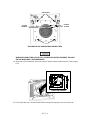
SECTION 5. OVEN TEMPERATURE . . . . . . . . . . . . . . . . . . . . . . . . . . . . . . .SVC 5- 1
REPLACING OVEN TEMPERATURE CONTROL . . . . . . . . . . . . . . . . . . . . . . . . . . . .
COMPONENTS
OVEN TEMPERATURE TROUBLESHOOTING . . . . . . . . . . . . . . . . . . . . . . . . . . . . . .
Replace Oven Shroud Assembly . . . . . . . . . . . . . . . . . . . . . . . . . . . . . . . . . . . . . . . . . . . . . .
Replace Oven Heater Element . . . . . . . . . . . . . . . . . . . . . . . . . . . . . . . . . . . . . . . . . . . . . . .
Replace Oven Temperature Sensor . . . . . . . . . . . . . . . . . . . . . . . . . . . . . . . . . . . . . . . . . . . .
Replace Oven Fan and/or Oven Fan Motor . . . . . . . . . . . . . . . . . . . . . . . . . . . . . . . . . . . . .
Replace Oven Flap Motor . . . . . . . . . . . . . . . . . . . . . . . . . . . . . . . . . . . . . . . . . . . . . . . . . . .
Replace Cryogenic Valve and/or Nozzle . . . . . . . . . . . . . . . . . . . . . . . . . . . . . . . . . . . . . . . .
Calibrate Oven Temperature . . . . . . . . . . . . . . . . . . . . . . . . . . . . . . . . . . . . . . . . . . . . . . . . .
SVC 5- 1
SVC 5SVC 5SVC 5SVC 5SVC 5SVC 5SVC 5SVC 5-
2
3
7
11
15
19
23
29
SECTION 6. ZONE TEMPERATURE . . . . . . . . . . . . . . . . . . . . . . . . . . . . . . .SVC 6- 1
REPLACING TEMPERATURE CONTROL
COMPONENTS
..................................
SVC TOC - 2
SVC 6- 1
ZONE TEMPERATURE TROUBLESHOOTING . . . . . . . . . . . . . . . . . . . . . . . . . . . . . .
Remove/Replace Inlet, Detector, and Valve Box . . . . . . . . . . . . . . . . . . . . . . . . . . . . . . . . .
Heater/Sensor Cable Assemblies
Disconnect/Connect Heater and Temperature Sensor . . . . . . . . . . . . . . . . . . . . . . . . . . . .
Wiring on Main PCB
Remove/Replace Inlet Zone Heater and Sensor Cartridges . . . . . . . . . . . . . . . . . . . . . . . .
`
Remove/Replace Packed Column Inlet Heater and Sensor Cartridges . . . . . . . . .
`
Remove/Replace Septum- Purged Packed Column Inlet
...................
Heater and Sensor Cartridges
`
Remove/Replace Split- Splitless/Split- Only Capillary Inlet . . . . . . . . . . . . . . . . .
Heater and Sensor Cartridges
` Remove/Replace PCOC Inlet Heater and Sensor Cartridges . . . . . . . . . . . . . . . . . . . .
Remove/Replace Detector Zone Heater and Sensor Cartridges . . . . . . . . . . . . . . . . . . . .
` Remove/Replace TCD Heater and Sensor Cartridges . . . . . . . . . . . . . . . . . . . . . . . . .
` Remove/Replace FID Heater and Sensor Cartridges . . . . . . . . . . . . . . . . . . . . . . . . . .
` Remove/Replace NPD Heater and Sensor Cartridges . . . . . . . . . . . . . . . . . . . . . . . . .
` Remove/Replace ECD (19233A/19235A VERSIONS) . . . . . . . . . . . . . . . . . . . . . . . .
Heater and Sensor Cartridges
` Remove/Replace ECD (G1223A/G1224A VERSIONS) . . . . . . . . . . . . . . . . . . . . . . .
Heater and Sensor Cartridges
` Remove/Replace FPD Heater and Sensor Cartridges . . . . . . . . . . . . . . . . . . . . . . . . . .
Remove/Replace Valve Box Heater and Sensor Cartridges . . . . . . . . . . . . . . . . . . . . . . . .
Replacing TCD Delta- T Temperature Sensor Cartridges . . . . . . . . . . . . . . . . . . . . . . . . .
Remove/Replace PCOC Inlet Cryogenic Cooling (Cryo- Blast) Weldment . . . . . . . . . . .
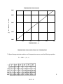
Temperature Sensor Data . . . . . . . . . . . . . . . . . . . . . . . . . . . . . . . . . . . . . . . . . . . . . . . . . . .
SVC 6- 3
SVC 6- 4
SVC 6- 4
SVC 6- 9
SVC 6- 9
SVC 6- 11
SVC 6- 13
SVC 6SVC 6SVC 6SVC 6SVC 6SVC 6-
16
18
18
20
24
28
SVC 6- 31
SVC 6SVC 6SVC 6SVC 6SVC 6-
34
37
39
42
45
SECTION 7. VALVES . . . . . . . . . . . . . . . . . . . . . . . . . . . . . . . . . . . . . . . . . . . . .SVC 7- 1
VALVES . . . . . . . . . . . . . . . . . . . . . . . . . . . . . . . . . . . . . . . . . . . . . . . . . . . . . . . . . . . . . . . . .
INTRODUCTION . . . . . . . . . . . . . . . . . . . . . . . . . . . . . . . . . . . . . . . . . . . . . . . . . . . . . . . . .
VALCO VALVES 18900F . . . . . . . . . . . . . . . . . . . . . . . . . . . . . . . . . . . . . . . . . . . . . . . . . . .
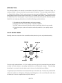
General Purpose Valves (GPVs) . . . . . . . . . . . . . . . . . . . . . . . . . . . . . . . . . . . . . . . . . . . . . .
Adjustable Restrictors . . . . . . . . . . . . . . . . . . . . . . . . . . . . . . . . . . . . . . . . . . . . . . . . . . . . . .
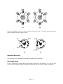
Gas Sample Loops . . . . . . . . . . . . . . . . . . . . . . . . . . . . . . . . . . . . . . . . . . . . . . . . . . . . . . . . .
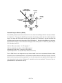
LIQUID SAMPLE VALVES (LSVs) . . . . . . . . . . . . . . . . . . . . . . . . . . . . . . . . . . . . . . . . . .
Troubleshooting and Maintenance . . . . . . . . . . . . . . . . . . . . . . . . . . . . . . . . . . . . . . . . . . . .
Chromatographic Symptoms . . . . . . . . . . . . . . . . . . . . . . . . . . . . . . . . . . . . . . . . . . . . . . . . .
Loss of Sensitivity or Excessive Drift . . . . . . . . . . . . . . . . . . . . . . . . . . . . . . . . . . . . . . . . . .
Loss of Peaks in Specific Areas of the Chromatogram . . . . . . . . . . . . . . . . . . . . . . . . . . . .
Baseline Upsets . . . . . . . . . . . . . . . . . . . . . . . . . . . . . . . . . . . . . . . . . . . . . . . . . . . . . . . . . . . .
Extraneous Peaks . . . . . . . . . . . . . . . . . . . . . . . . . . . . . . . . . . . . . . . . . . . . . . . . . . . . . . . . . .
Locating Leaks . . . . . . . . . . . . . . . . . . . . . . . . . . . . . . . . . . . . . . . . . . . . . . . . . . . . . . . . . . . .
Pressure Check . . . . . . . . . . . . . . . . . . . . . . . . . . . . . . . . . . . . . . . . . . . . . . . . . . . . . . . . . . . .
Valve Box Assembly Removal . . . . . . . . . . . . . . . . . . . . . . . . . . . . . . . . . . . . . . . . . . . . . . . .
Valve Actuator Alignment . . . . . . . . . . . . . . . . . . . . . . . . . . . . . . . . . . . . . . . . . . . . . . . . . . .
Valve Actuation of GC- Controlled Valves . . . . . . . . . . . . . . . . . . . . . . . . . . . . . . . . . . . . .
Valve Configuration Diagrams . . . . . . . . . . . . . . . . . . . . . . . . . . . . . . . . . . . . . . . . . . . . . . .
SVC TOC - 3
SVC 7SVC 7SVC 7SVC 7SVC 7SVC 7SVC 7SVC 7SVC 7SVC 7SVC 7SVC 7SVC 7SVC 7SVC 7SVC 7SVC 7SVC 7SVC 7-
1
2
2
4
5
5
6
7
7
7
7
7
8
8
8
15
16
17
18
SECTION 8. KEYBOARD AND DISPLAY . . . . . . . . . . . . . . . . . . . . . . . . . . .SVC 8- 1
KEYBOARD AND DISPLAY REPLACEMENT . . . . . . . . . . . . . . . . . . . . . . . . . . . . . . . SVC 8- 1
KEYBOARD AND DISPLAY TROUBLESHOOTING . . . . . . . . . . . . . . . . . . . . . . . . . SVC 8- 2
Replace Display PCB Assembly . . . . . . . . . . . . . . . . . . . . . . . . . . . . . . . . . . . . . . . . . . . . . . SVC 8- 3
SECTION 9. MAIN PCB . . . . . . . . . . . . . . . . . . . . . . . . . . . . . . . . . . . . . . . . . .SVC 9- 1
MAIN PCB . . . . . . . . . . . . . . . . . . . . . . . . . . . . . . . . . . . . . . . . . . . . . . . . . . . . . . . . . . . . . . .
Replace Main PCB . . . . . . . . . . . . . . . . . . . . . . . . . . . . . . . . . . . . . . . . . . . . . . . . . . . . . . . . .
SVC 9- 1
SVC 9- 2
SECTION 10. DATA COMMUNICATIONS . . . . . . . . . . . . . . . . . . . . . . . . . .SVC 10- 1
COMMUNICATION INTERFACE COMPONENTS . . . . . . . . . . . . . . . . . . . . . . . . . . .
Replace Communications Interface PCB . . . . . . . . . . . . . . . . . . . . . . . . . . . . . . . . . . . . . . .
Replace Rear Panel Connector PCB and/or Cable for DICE PCB . . . . . . . . . . . . . . . . . .
INET CONFIGURATION . . . . . . . . . . . . . . . . . . . . . . . . . . . . . . . . . . . . . . . . . . . . . . . . . .
Switching Between “Global”and “Local” . . . . . . . . . . . . . . . . . . . . . . . . . . . . . . . . . . . . . .
INET/HP- IL Adresses . . . . . . . . . . . . . . . . . . . . . . . . . . . . . . . . . . . . . . . . . . . . . . . . . . . . .
Verifying the HP 5890 Series II INET Address . . . . . . . . . . . . . . . . . . . . . . . . . . . . . . . . . .
Setting the Default HP- IL Address . . . . . . . . . . . . . . . . . . . . . . . . . . . . . . . . . . . . . . . . . . .
INET- HP 5890 Signal Definition . . . . . . . . . . . . . . . . . . . . . . . . . . . . . . . . . . . . . . . . . . . .
HP- IL Loopback Test . . . . . . . . . . . . . . . . . . . . . . . . . . . . . . . . . . . . . . . . . . . . . . . . . . . . . .
SVC 10SVC 10SVC 10SVC 10SVC 10SVC 10SVC 10SVC 10SVC 10SVC 10-
1
2
5
8
8
9
10
10
10
12
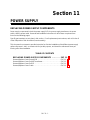
SECTION 11. POWER SUPPLY . . . . . . . . . . . . . . . . . . . . . . . . . . . . . . . . . . . .SVC 11- 1
REPLACING POWER SUPPLY COMPONENTS . . . . . . . . . . . . . . . . . . . . . . . . . . . . . .
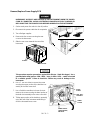
Remove/Replace Power Supply PCB . . . . . . . . . . . . . . . . . . . . . . . . . . . . . . . . . . . . . . . . . .
Remove/Replace Power Supply Transformer . . . . . . . . . . . . . . . . . . . . . . . . . . . . . . . . . . . .
Remove/Replace Power Switch . . . . . . . . . . . . . . . . . . . . . . . . . . . . . . . . . . . . . . . . . . . . . . .
Remove/Replace Power Cable . . . . . . . . . . . . . . . . . . . . . . . . . . . . . . . . . . . . . . . . . . . . . . . .
SVC 11SVC 11SVC 11SVC 11SVC 11-
1
2
5
9
11
APPENDIX A. PCB CONNECTOR INFORMATION . . . . . . . . . . . . . . . . . . APX A- 1
AC POWER PCB CONNECTORS . . . . . . . . . . . . . . . . . . . . . . . . . . . . . . . . . . . . . . . . . . .
120VAC BOARD . . . . . . . . . . . . . . . . . . . . . . . . . . . . . . . . . . . . . . . . . . . . . . . . . . . . . . . . . .
220VAC SINGLE PHASE BOARD . . . . . . . . . . . . . . . . . . . . . . . . . . . . . . . . . . . . . . . . . . .
220VAC SPLIT PHASE BOARD . . . . . . . . . . . . . . . . . . . . . . . . . . . . . . . . . . . . . . . . . . . . .
MAIN PCB CONNECTORS . . . . . . . . . . . . . . . . . . . . . . . . . . . . . . . . . . . . . . . . . . . . . . . .
P1 KEYBOARD CONNECTOR . . . . . . . . . . . . . . . . . . . . . . . . . . . . . . . . . . . . . . . . . . . .
P2 DETECTOR A PCB CONNECTOR . . . . . . . . . . . . . . . . . . . . . . . . . . . . . . . . . . . . . .
P3 DETECTOR B PCB CONNECTOR . . . . . . . . . . . . . . . . . . . . . . . . . . . . . . . . . . . . . . .
P4 ANALOG SIGNAL 1 OUTPUT CONNECTOR . . . . . . . . . . . . . . . . . . . . . . . . . . . .
P5 ANALOG SIGNAL 2 OUTPUT CONNECTOR . . . . . . . . . . . . . . . . . . . . . . . . . . . .
P6 REMOTE START CONNECTOR . . . . . . . . . . . . . . . . . . . . . . . . . . . . . . . . . . . . . . . .
P7 TEMPERATURE SENSOR CONNECTOR . . . . . . . . . . . . . . . . . . . . . . . . . . . . . . . .
P8 OVEN FLAP MOTOR CONNECTOR . . . . . . . . . . . . . . . . . . . . . . . . . . . . . . . . . . . .
J9 CRYOGENIC VALVE AND AUX HEATED ZONE CONNECTOR . . . . . . . . . . .
P10 AC POWER SUPPLY CONNECTOR . . . . . . . . . . . . . . . . . . . . . . . . . . . . . . . . . . . .
P11 ELECTRONIC FLOW SENSOR CONNECTOR . . . . . . . . . . . . . . . . . . . . . . . . . . .
P12 EPC/MPC PCB CONNECTOR . . . . . . . . . . . . . . . . . . . . . . . . . . . . . . . . . . . . . . . . . .
P13 COMMUNICATIONS PCB CONNECTOR . . . . . . . . . . . . . . . . . . . . . . . . . . . . . . .
J14 AUXILIARY CONNECTOR . . . . . . . . . . . . . . . . . . . . . . . . . . . . . . . . . . . . . . . . . . . .
P15 WORKFILE EMULATION CONNECTOR . . . . . . . . . . . . . . . . . . . . . . . . . . . . . . .
DISPLAY PCB . . . . . . . . . . . . . . . . . . . . . . . . . . . . . . . . . . . . . . . . . . . . . . . . . . . . . . . . . . . .
DETECTOR PCBS . . . . . . . . . . . . . . . . . . . . . . . . . . . . . . . . . . . . . . . . . . . . . . . . . . . . . . . .
EPC PCB CONNECTORS . . . . . . . . . . . . . . . . . . . . . . . . . . . . . . . . . . . . . . . . . . . . . . . . . .
EPC PRESSURE TRANSDUCER MODULE . . . . . . . . . . . . . . . . . . . . . . . . . . . . . . . . .
EPC PROPORTIONAL CONTROL VALVE . . . . . . . . . . . . . . . . . . . . . . . . . . . . . . . . . .
MPC PCB . . . . . . . . . . . . . . . . . . . . . . . . . . . . . . . . . . . . . . . . . . . . . . . . . . . . . . . . . . . . . . . .
RS232C PCB CONNECTORS . . . . . . . . . . . . . . . . . . . . . . . . . . . . . . . . . . . . . . . . . . . . . . .
SVC TOC - 4
APX AAPX AAPX AAPX AAPX AAPX AAPX AAPX AAPX AAPX AAPX AAPX AAPX AAPX AAPX AAPX AAPX AAPX AAPX AAPX AAPX AAPX AAPX AAPX AAPX AAPX AAPX A-
3
3
3
4
5
5
6
7
7
8
8
8
9
9
9
10
11
12
12
12
13
14
15
16
16
17
18
INET PCB . . . . . . . . . . . . . . . . . . . . . . . . . . . . . . . . . . . . . . . . . . . . . . . . . . . . . . . . . . . . . . . .
BUFFERED INET PCB . . . . . . . . . . . . . . . . . . . . . . . . . . . . . . . . . . . . . . . . . . . . . . . . . . . .
DICE PCB . . . . . . . . . . . . . . . . . . . . . . . . . . . . . . . . . . . . . . . . . . . . . . . . . . . . . . . . . . . . . . . .
DICE CONNECTOR PCB . . . . . . . . . . . . . . . . . . . . . . . . . . . . . . . . . . . . . . . . . . . . . . . . . .
ELECTRONIC FLOW SENSOR MODULE . . . . . . . . . . . . . . . . . . . . . . . . . . . . . . . . . . .
VALVE PCB CONNECTORS . . . . . . . . . . . . . . . . . . . . . . . . . . . . . . . . . . . . . . . . . . . . . . .
SVC TOC - 5
APX AAPX AAPX AAPX AAPX AAPX A-
19
20
21
22
24
25
Section 1
INTRODUCTION
HP 5890 SERIES II GAS CHROMATOGRAPH
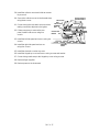
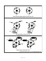
This section is intended to help the technician isolate problems to a specific component or components. The HP 5890 Series II may be found in many different configurations, with varying component
options. This complicates the process of providing detailed troubleshooting procedures for even general problems. But, by using the general troubleshooting techniques presented here, along with the functional diagrams found at the end of this section, successful results should be achieved.
There are five inlet options and six detector options which may be encountered when servicing an HP
5890 Series II Gas Chromatograph, as well as a wide variety of flow and pressure control components.
All of these common inlet and detector components are represented by the functional diagrams at the
end of this section. When troubleshooting inlets, detectors, and/or the flow/pressure systems, fold out
the page corresponding to the employed detector, while leaving the book open to the page corresponding to the employed inlet. Maintenance procedures for most of the components are given in the
following sections. Procedures are supplied to remove, replace, and/or clean various subassemblies,
based on the current maintenance philosophy, i. e., to allow replacement of the lowest level components applicable for a particular item.
Specific part numbers are not given in this portion of the service manual. For all replacement part numbers, refer to the IPB portion of this document.
This document is not meant to provide instruction for first time installation of any of the options discussed. The add- on sheets, which accompany the various options, exist for just this purpose, and
should be referenced when performing a first time installation.
TABLE OF CONTENTS
HP 5890 SERIES II GAS CHROMATOGRAPH . . . . . . . . . . SVC 1- 1
Electronic Troubleshooting . . . . . . . . . . . . . . . . . . . . . . . . . . . . . . . . . . . . . . SVC 1INTRODUCTION . . . . . . . . . . . . . . . . . . . . . . . . . . . . . . . . . . . . . . . . . . . . . . . SVC 1Recommended Test Equipment . . . . . . . . . . . . . . . . . . . . . . . . . . . . . . . . . . SVC 1PART A NON- FUNCTIONING INSTRUMENT . . . . . . . . . . . . . . . . . . . . SVC 1Fuse Information . . . . . . . . . . . . . . . . . . . . . . . . . . . . . . . . . . . . . . . . . . . . . . . SVC 1Power On Sequence . . . . . . . . . . . . . . . . . . . . . . . . . . . . . . . . . . . . . . . . . . . . SVC 1PART B AUTOMONITOR MESSAGES . . . . . . . . . . . . . . . . . . . . . . . . . . SVC 1PART C OPERATOR INSTIGATED INDICATIONS . . . . . . . . . . . . . . . . . SVC 1Test Chromatogram Signal Output Test . . . . . . . . . . . . . . . . . . . . . . . . . . . SVC 1PART D FUNCTIONAL SYMPTOMS . . . . . . . . . . . . . . . . . . . . . . . . . . . . SVC 1-
SVC 1- 1
2
2
2
3
3
4
5
8
10
11
Electronic Troubleshooting
INTRODUCTION
This section is intended to aid the operator and service engineer in the troubleshooting process, i.e., of
going from symptom to cause. It has been subdivided into four subsections by type of symptom.
Part A covers the most obvious indications of problems. The instrument apparently (generally when
first turned on) doesn’
t work at all. (NON- FUNCTIONING INSTRUMENT)
Part B includes the symptoms that can appear as a visual indication or message on the front of the
keyboard/display module. These messages are a result of the instrument’
s extensive automonitoring
system. (AUTOMONITOR MESSAGES)
Part C discusses the visual information that the operator can instigate and use as part of the troubleshooting process. These visual indications are normally not available unless specifically requested by
the operator. (OPERATOR INSTIGATED INDICATIONS)
Part D contains symptoms (other than those that appear on the visual display) that indicate a possible
problem. Typically, these types of symptoms can be associated with a specific functional area of the
instrument. (FUNCTIONAL SYMPTOMS )
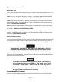
Electrical Safety Precautions
In all nonelectrically oriented sections of this manual, the standard Hazardous Voltage Warning strongly
recommends turning off all of the power to the instrument. However, this section, as well as most of
Service Section, requires that some electrical measurements be made on active (energized) circuits.
MEASUREMENTS AND/OR TESTS THAT NEED TO BE MADE ON ELECTRICALLY
ENERGIZED PORTIONS OF THE INSTRUMENT SHOULD BE PERFORMED ONLY BY
SERVICE- TRAINED PERSONNEL WHO ARE AWARE OF ALL INVOLVED HAZARDS.
The Service Section of this manual contains proper step by step procedures for replacing electronic
boards and other major assemblies. These procedures include instructions that should be followed for
both personnel and instrument welfare.
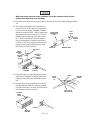
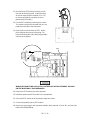
`
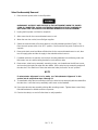
The following steps require protection against ESD (Electro- Static Discharge).
Use a grounded wrist strap (part no. 9300- 0969 - large, or 9300- 0970 - small)
connected to a suitable ground. Failure to heed this caution may result in
damage to the instrument.
`
When storing or in between handling of PCBs (Printed Circuit Boards), always
place them in static control envelopes or enclosures.
Recommended Test Equipment
The only piece of test equipment required to troubleshoot the instrument is a good, volt/ohmmeter.
SVC 1- 2
PART A
NON- FUNCTIONING INSTRUMENT
A totally non- functioning or DEAD instrument is one that apparently isn’
t working at all. It has no visual
indications (i.e., messages) on its front panel and produces no noise or heat.
The most obvious cause for such a problem is that line power is not reaching the instrument or that the
instrument is not turned on. First check that the Line Power Switch is ON. Then verify that the instrument power cord is plugged into a proper receptacle. If neither of these acts restore the instrument to
operation, suspect that there may be a problem with the receptacle or the power being supplied to it.
This type of situation generally requires that a local electrical maintenance person be informed to remedy the problem. However, on the rare occasion that power is being provided, but the instrument is not
working, the problem area must be isolated by tests and measurements on the instrument.
MEASUREMENTS AND/OR TESTS THAT NEED TO BE MADE ON ELECTRICALLY
ENERGIZED PORTIONS OF THE INSTRUMENT SHOULD BE PERFORMED ONLY BY
SERVICE- TRAINED PERSONNEL WHO ARE AWARE OF ALL INVOLVED HAZARDS.
Any one of several problems internal to the instrument can cause the non- functioning symptom. Since
the instrument operates under processor control, a faulty component in the CPU or Clock sections of
the Main Board may be the source of the problem. More commonly, a problem in the instrument’
s power supply would be the most likely to cause this type of problem.
Two bits of information, plus the use of IPB, should enable service- trained personnel to isolate and
then correct the cause of the problem if it is power related. The first important bit of information is about
the fuses that are internal to the instrument. The second bit is the normal sequence of events that occurs as the instrument is energized (Power On Sequence).
Fuse Information
Fuses have been installed at several locations within the instrument for the protection of major power
circuits. They are designed to open as quickly as possible to prevent damage to other components
within the circuit. Occasionally, an opened fuse may have been caused by a short onetime surge; however, it is far more common that a component within the protected circuit has failed. When an open fuse
is noticed, replace it once. If the replacement blows, suspect a component failure.
Fuses are located on the AC Power Board and on the Main Board. The AC Power Board fuses protect
the two high- power circuits. One fuse, (F1) or two in a split phase circuit (F3 & F4), protects the column oven heater and fan. Another fuse (F2) or two in a split phase circuit (F1 & F2) protects the main
power transformer. (Refer to Section 8 of the IPB portion of this document for power supply PCB information. Refer to Section 9 of the IPB portion of this document for main PCB information.)
The three secondary voltages of the main power transformer are protected with fuses located on the
Main Board. F3 protects the 120 VAC secondary which ultimately provides heater power for all of the
zones. F4 and F5 protect the 40 VAC secondary which ultimately provides all of the DC supply voltages
(+5, +10, +15, - 15, +24, - 24). Fuses protect the 3 VAC secondary that is used for FID ignitor (F1)
and electronic flow sensor voltages (F2).
SVC 1- 3
Power On Sequence
As long as correct Line Voltage is provided to the instrument, the following events should occur when
the instrument’
s Line Power Switch is placed in its ON position. Main Transformer (T1) primary winding
is energized (fused by F2 on AC Board or F1 & F2 if split phase). (Refer to Section 9 of the IPB portion
of this document for main PCB information.)
The three secondary windings (3 VAC, 40 VAC, and 120 VAC) of T1 are energized. All are fused on the
Main Board. These voltages arrive on the main board through connector J10. (Refer to appendix A of
this document for all connector information.)
The 40 VAC is rectified and divided to produce +24 VDC and +15 VDC.
From these DC supplies, the +10 VDC, the +5 VDC, and the Master Oscillator (for clocks) begin to
function.
As these other supplies begin, the (POWER ON PULSE) and the CPU portion of the circuitry begin to
initialize, first themselves, and then through the Data Bus and other portions of the instrument.
One of the initializations that occurs through the Data Bus is in the Triac Control section to produce the
control signal for K3 (zone power relay) on the Main Board and the signal for K1 ( oven contactor) on
the AC Board.
K3 relay allows distribution of the fused 120 VAC secondary from the Main Transformer.
K1 power contactor on the AC Board allows line power distribution to the Oven Fan Motor and to the
Oven Heater Triac circuit. Note that the oven fan will run as long as power is allowed (under software
control) through K1. However, the oven heater is NOT energized until oven heat is requested.
SVC 1- 4
PART B
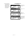
AUTOMONITOR MESSAGES
This section includes the symptoms that can appear as a visual indication or message on the front of
the keyboard/display module. These messages may appear (depending upon their seriousness) either
at the time that the problem occurs or in the instrument’
s Self Test.
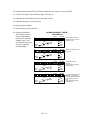
Messages resulting from the automonitoring software within the instrument will be one of four classes:
FATAL ERR:
H2 ALARM FAULT:
WARN:
The FATAL ERR: message is the most serious. This class of message indicates that the HP 5890 SERIES II is essentially nonfunctional. The instrument will always go to a NOT READY state and even the
keyboard is inoperative.
FATAL ERR: EPP & FLOW Indicates Electronic Pressure Control (EPC) and Electronic Flow Sensor(EFS) modules are installed simultaneously. The instrument must be powered down and one of two
modules must be removed to correct this situation. No damage should occur to the instrument.
FATAL ERR: BAD RAM indicates a problem with RAM chip and its circuitry in the CPU Section of Main
Board. Replace Main Board.
FATAL ERR: BAD ROM indicates a problem with ROM chip and its circuitry in the CPU Section of Main
Board. Replace Main Board.
FATAL ERR: > !25 MS indicates that the 40 Hz task couldn’
t complete within !25 milliseconds. Suspect
a problem with the Clock Section of the Main Board; however, the CPU Section could also cause this
indication. Replace Main Board.
FATAL ERR: STACK ERR indicates that stack is beyond legal limits. Suspect a problem in the CPU Section of the Main Board. Replace Main Board.
FATAL ERR: RUN CNTL indicates that the Run Control task couldn’
t complete within 25 milliseconds.
Suspect a problem with the Clock Section of the Main Board; however, the CPU Section could also
cause this indication. Replace Main Board.
As can be seen from the FATAL ERR: message listing above, they are generally an indication that a failure exists either in the Clock or CPU Sections of the Main Board. The Clock Section operation can be
easily checked by measuring the frequencies on its outputs. Once the clocks are verified to be good,
the CPU (Z80) could be checked by substitution.
The H2 ALARM message indicates a failure of the system to hold or reach the electronic pressure setpoint. All electronic pressures and heated zones will be shut off. To recover, the problem must be corrected and the GC power cycled.
H2 ALARM - EPP A indicates electronic pressure problem with
the A systems ability to hold pressure. Possibly a leak, trouble shoot the proportional control valve,
pressure transducer and the inlet in the case of the EPC. Trouble shoot the forward pressure regulator
and gage in the case of the MPC.
SVC 1- 5
H2 ALARM - EPP B indicates electronic pressure problem with
the B systems ability to hold pressure. Possibly a leak, trouble shoot the proportional control valve,
pressure transducer and the inlet in the case of the EPC. Trouble shoot the forward pressure regulator
and gage in the case of the MPC.
The FAULT: message indicates that a major subsystem of the HP 5890 SERIES II is not functioning
properly. Although the operation of the suspected subsystem is suspended until the problem is corrected, the balance of the GC is operational. Note that the instrument can never reach a fully READY
state when a FAULT condition exists.
FAULT: ADC OFFSET indicates a problem with the thermal ADC offset reading. Replace the Main
Board.
FAULT: LINE SENSE indicates a problem either with the actual line voltage or with the sensing circuit.
Measure the line voltage and if the measurement is between +5% and- 10% of the instruments stated
rating then the line voltage is O.K. Determine if the 120 VAC secondary exists and if its fuse (F3) is
open. If both F3 and the 120 VAC secondary are good then their is a failure in the line sense circuit and
the main board should be replaced.
FAULT: OVEN > MAX+20 indicates that the oven senses its temperature has exceeded the current
setpoint value by more than 20 degrees C. This message (as any FAULT message regarding a temperature problem) shuts down all of the temperature systems. The problem could be either in the oven
sensing or in the oven control circuits. List the oven temperature; if the display indicates that the actual
valve is above 800 degrees C, most likely the oven sensor is open (although it could be some component in the sensing circuit). If the actual value of the oven temperature seems reasonable, the problem
is likely to be in the oven control circuitry.
FAULT: (ZONE NAME) TEMP RDG where the ZONE NAME could be OVEN, INJA, INJB, DETA,
DETB, or AUX. Any of these messages indicates that the specified zone (or oven) temperature reading
was out of acceptable range. This most often is the result of an inoperative sensor in the named zone.
FAULT: (OUTPUT NAME) TEST where the OUTPUT NAME could be DAC1, DAC2, ATTN1, or
ATTN2. If thermal fault messages also appear, suspect the A/D Converter circuitry. The A/D Converter
section of the Main Board is used to measure DAC and ATTN outputs. However, if only this test message appears, the most obvious area to suspect is the D/A Converter portion of the appropriate board.
DAC2 or ATTN2 indicates the D/A section of the Interface Board; whereas the DAC1 or ATTN1 indicates the D/A portion of the Main Board. Other areas that could be at fault include the CPU and A/D
sections of the Main Board, but are less likely. Occasionally, multiple faults messages may exist at the
same time. Only the last message to occur will automatically be displayed on the front panel of the instrument. Others will be retained in the instrument’
s memory. By pressing the CLEAR key, the instrument will roll through all of its Not Ready states (which include all FAULTs).
FAULT: EPP RAM TEST indicates the RAM has failed selftest. This requires board replacement.
FAULT: EPP ROM TEST indicates the ROM has failed selftest and should be replaced.
FAULT: INET CPU indicates that the Communications Interface Board is not responding properly. Typically, this message is caused by a faulty microprocessor (CPU) on the Interface Board.
FAULT: INET CPU RAM indicates that the read/write memory internal to the CPU on the Interface
Board is not functioning as expected. Replace either the Interface Board or its CPU.
SVC 1- 6
FAULT: INET RAM indicates that the RAM chip on the Interface Board is not responding properly. Typically, the RAM chip on the Interface Board should be replaced.
FAULT: INET ROM indicates that the ROM chip on the Interface Board is not responding properly. Typically, the ROM chip on the Interface Board should be replaced.
Another good technique to investigate multiple messages, after noting the currently displayed message, is to switch the power line switch of the instrument off, and then on. This will force the instrument
to process through its initializing SelfTest. During this testing sequence, indications other than the previously displayed message may appear to provide more information.
By running the instrument SelfTest ((either at power turn- on or through the Calib and Test (Clear Dot)
Modes)), WARN: messages may appear.
The WARN: message indicates that a condition exists that may need attention. Generally, the instrument remains fully operational, except for the function indicated on the visual display. Pressing any instrument function will erase the WARN: message. The following five WARN: messages will only appear
via the SelfTest.
WARN: MEMORY RESET indicates that the instrument memory has been reset to the default setpoints
including flow and oven calibrations. This could have been done by operator keyboard entry (see Section 13 of this manual), by RAM replacement, or by removing the battery.
WARN: SIGNAL CHANGED indicates that a detector that was previously assigned to a particular signal
is no longer recognized. The instrument will reconfigure the signal. This may occur as a result of detector boards having been removed during a repair. If these boards have not been recently removed, suspect a failure and refer to Detector Problems later in this section.
WARN: NO DETECTORS indicates that no detector boards are installed or that they are not recognized as being installed by the processor. If detector boards are physically installed and not recognized,
suspect the boards, the I/O section, or the CPU section of the Main Board.
The WARN: OVEN SHUT OFF message is somewhat of a hybrid between other WARN: messages
and a FAULT: message. Similar to other WARN: messages, the WARN: OVEN SHUT OFF message
occurs most often as a result of inoperative hardware (rather than software). This may be something as
simple as the operator leaving the oven door open. However, different from other WARN: (similar to
FAULT:) messages, the WARN: OVEN SHUT OFF message may occur any time that conditions warrant. The operator need not run the SelfTest for this message to be displayed. WARN: OVEN SHUT
OFF indicates that the oven temperature has been shut off because it could not heat as quickly as it
should or because it cooled more slowly than it should. Suspect that the oven flap could be stuck, or
that a large thermal leak from the oven has occurred (make sure that the oven door is shut). Once the
WARN: OVEN SHUT OFF is displayed, the oven temperature will remain off until the message is
cleared. The operator need only to press the
SVC 1- 7
PART C
OPERATOR INSTIGATED INDICATIONS
This section discusses the visual information that the operator can instigate and use as part of the troubleshooting process. These visual indications are normally not available unless specifically requested
by the operator.
There are several functions of the CALIB AND TEST (Clear Dot) modes that can be used as a diagnostic tool. Similarly, the TEST CHROMATOGRAM can be extremely useful. Each of these operator instigated functions is specifically designed to aid the overall troubleshooting process and is activated from
the keyboard.
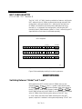
Of the ten functions accessible through the CALIB AND TEST (Clear Dot), five may be thought of as
servicing functions. The other five functions are generally thought of as operational functions. These are
explained in the operation and reference manuals.
To enter any of the CALIB AND TEST (Clear Dot) modes, press: the Clear key, the Decimal key and a
number from 0 through 9. The actual digits 4,5,7,8,9 represent the typical test modes. These are as
follows:
CLEAR DOT 4
DISPLAY MEMORY
CLEAR DOT 5
SELFTEST
CLEAR DOT 7
HPIL LOOPBACK TEST
CLEAR DOT 8
SET PID CONTROLS
CLEAR DOT 9
DISP TEMP & DEMAND
To escape from any of the CALIB AND TEST (Clear Dot) modes press any of the instrument function
keys.
Calib and Test (Clear Dot 4) Display Memory
This diagnostic routine is initiated from the keyboard by pressing: Upon entering this mode, a single
memory address (ADDR:) and a value (VAL:) will appear on the instrument front panel visual display.
At this time, both the address and the value will be displayed in hexadecimal. In this hexadecimal
mode, the value displayed is two bytes (four digits) of information. The rightmost two digits (one byte)
represent the actual contents of the indicated address. The other two digits correspond to the contents
of the next address. For example, if address 1111 were keyed in and the value F224 resulted, 24 is
the contents of address 1111 and F2 is the contents of address 1112. This could be verified by addressing 1112; then the F2 would become the two rightmost digits (i.e., 3DF2).
In the Display Memory mode, some keys on the keyboard are redefined:
A key becomes A in hexadecimal.
B key becomes B in hexadecimal.
COL COMP1 key becomes C in hexadecimal.
COL COMP2 key becomes D in hexadecimal.
ON key becomes E in hexadecimal.
OFF key becomes F in hexadecimal.
The Decimal Point key increments the address.
SVC 1- 8
The Minus key decrements the address.
The ENTER key switches the type of value presentation. The binary display mode can be entered from
the hexadecimal mode by pressing . If already in the binary mode, it will return to the hexadecimal
mode.
The binary mode is very similar to the hexadecimal mode except that the value of the address, and only
that value (one byte), is displayed in the binary code. If the next value (one byte in binary) is desired,
simply increment the address, which is always displayed in hexadecimal. The incrementing and decrementing of addresses in the binary mode are done in the same manner as in the hexadecimal mode.
To leave this Display Memory routine, press any of the instrument function keys. This also reestablishes
the normal key definitions.
Calib and Test (Clear Dot 5) SelfTest
This instrument test is exactly the same as the one that occurs automatically at power turn on, except it
is entered whenever the operator decides. It is initiated from the keyboard by pressing: The first indication a user has that the instrument is working is when the unit tests its RAM (Random Access Memory)
and the visual display portion of the front panel. The entire visual display (all possible dots) and all LEDs
turn on for a few seconds.
The next indication is when the unit displays TESTING MEMORY. During this time, the unit tests most
of the processor memory (ROM) circuits. Note that during this time only the NOT READY LED remains
lit.
The third indication is when the unit displays TESTING SIGNAL PATH. During this phase of the selftest,
the unit actually exercises most of the signal handling sections of the Main Board. Note that the analog
sensors (i.e., temperature sensors) are NOT tested at this time; they are tested after the selftest. However, by linking the A/D through the CPU to the D/A and by looping the D/A output back as an input to
the A/D, most of the Main Board’
s signal handling circuits are checked.
The fourth (and unless an error is found, the final) indication is the PASSED SELFTEST message. This
message verifies that the selftest sequence has been completed. The PASSED SELFTEST display remains until some further action is taken by the operator or some area not tested during the SelfTest is
detected.
By pressing the clear key, the visual display should change to some message about OVEN TEMP. This
action, with its resulting message, verifies that the keyboard is communicating with the CPU.
Calib and Test (Clear Dot 7)
HPIL Loopback Test This diagnostic test requires that one of the HPIL cables be connected from the
OUT to the IN. The test is then initiated from the keyboard by pressing: By entering this test, 128 frames
will be transmitted from the CPU through the Communications Interface Board. With the HPIL cable installed, the same word should be transmitted back to the Z80 processor, sensed and compared with
the transmitted word. If the comparison verifies correct transmission and reception, a PASSED SELFTEST message will be displayed on the instrument’
s front panel visual display. Note that this is the
HPIL SelfTest and is not the same as the instrument SelfTest done at power turn on.
If a component failure exists in the HPIL circuitry, or if either the Interface Board or HPIL Cable is not
properly installed, a FAILED SELFTEST message will be displayed.
SVC 1- 9
To leave this mode of testing, press any of the instrument function keys.
Calib and Test (Clear Dot 8) Set PID Controls
Calib and Test (Clear Dot 9) Disp Temp & Demand
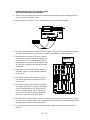
Test Chromatogram Signal Output Test
This diagnostic test is selected from the keyboard by pressing One of the signal selection keys either
SIG 1 or SIG 2 and the 9 key on the numeric key pad and the ENTER key. Test plot mode is confirmed
by the display showing SIGNAL 1 (or 2) TEST PLOT. Pressing SIG 1 (or 2) a second time displays
the current signal level value (which is 0.0 initially). This permits monitoring the output signal.
The test chromatogram, which is permanently stored in the HP 5890 SERIES II, is initiated by pressing
the START key. Each chromatographic cycle consists of three peaks. Each peak is about 1/10 the
height of the previous peak, with the first (tallest) peak having a height value of about 125 mV at = 0
(+1 V analog output); halfheight width of this peak is about 0.13 minutes. Each cycle is about 1.5 minutes in length. The chromatogram will continue to cycle until the STOP key is pressed. The test chromatogram is useful as a troubleshooting aid in deciding whether a lost or noisy signal observed at a connected integrating or chart recording device is due to a chromatographic problem (lost sample due to
leaks, noise due to a dirty detector, etc.), versus problems either with the integrating/recording device
itself, or in its connecting cables.
If the test chromatogram does not exhibit any problems at the integrating/recording device, a chromatographic problem is likely to exist; if the test chromatogram exhibits noise, or does not appear at all, the
problem is most likely to be hardware related. Check setpoints on both the HP 5890 SERIES II and the
integrating/recording device.
SVC 1- 10
PART D
FUNCTIONAL SYMPTOMS
This section contains symptoms (other than those that appear on the visual display) that indicate a possible problem. Typically, these types of symptoms can be associated with a specific functional area of
the instrument.
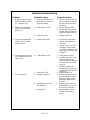
Zone doesn’
t heat all other zones O.K.
With an Ohm meter measure the resistance of the cartridge heater (should be about 200- 220 ohms).
With the power removed this can be measured by removing the J9 connector for INJA, INJB, DETA,
and DETB. To measure the AUX zone remove the J14 connector. The pins are labeled on the main
board next to the appropriate J connector. Replace the cartridge heater if it is open or shorted. If the
cartridge heater tests O.K. and sensor test O.K. (see temperature sensor resistance chart), the problem
is in the zone control on the main board and the main board should be replaced. To measure resistance of sensors remove connector P7, sensors are labeled on main PCB.
Zone temperature is unstable.
If Zone will not reach desired temperature or cycles over more then plus or minus 1 degree C then the
insulation around the zone and the insulation of the oven shell should be examined and additional insulation added if necessary. Also refer to the operating manual to verify the zone is being used properly(i.e., oven at - 50 degrees C, injection port at 100 degrees C). This type of operation will not work.
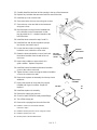
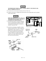
The Main Board is generally serviced from a replacement aspect, the introduction includes an illustration of its functional configuration followed by information about its connectors and test points.
Any replacement or space electrical parts that are subject to damage by static electricity will be shipped
in static- protective bags or containers. Be certain to utilize these protective devices when storing items
of this nature.
Generally, since board or module replacement constitutes the majority of electronic repairs, the only
electronic test equipment necessary is a quality Volt Ohm Ampmeter.
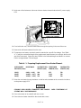
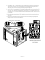
The HP 5890 Series II GC contains a minimum of four and a maximum of nine electronic boards. The
four boards always installed are one of the AC Power Boards, the Keyboard and Display Board(usually
done as one module), and the Main Board. The actual AC Power Board located in the rear of the instrument behind the column oven compartment is one of three possible boards based on the voltage and
phase configuration of the line. The Keyboard and Display Board are two boards located on the front of
the Electronics Module. The Keyboard plugs directly into the Display Board. The Main Board is
mounted inside the right side panel of the instrument and occupies most of the space in the Electronics
Module. More importantly, the Main Board contains most of the instrument’
s electronics.
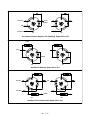
General Description:
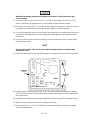
The 05890- 60015 PC board is a collection of circuits which allow operation of the 5890 Series II gas
chromatograph. The circuits on the new board include power supplies, CPU, A/D converter, D/A converter, clocks and general control circuits. (Refer to the main PCB diagrams, pages SVC 1 - 12 and
SVC 1 - 13.)
The functions provided by the new PC board are the same as those provided by the original HP 5890A
GC except that components have been added to control an additional heated zone and 2 AC valves.
The new board differs only in its implementation of these functions. The foremost change is the use of
a 68 pin PLCC custom IC which performs the same functions as do 26 TTL IC’
s on the original
05890- 60010 board
SVC 1- 11
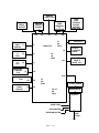
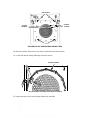
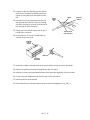
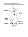
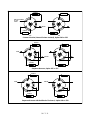
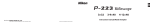
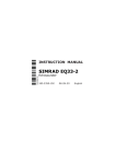
Connectors 1 thru 15 are used to connect the Main Board either with the other electronic assemblies
within the instrument or external devices, such as an integrator. (Refer to the main PCB diagrams,
pages SVC 1 - 13 and SVC 1 - 14. Refer to appendix a of this document for information on the main
PCB connectors.)
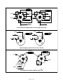
SVC 1- 12
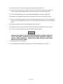
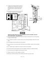
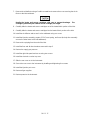
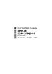
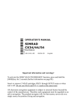
MAIN PCB FUNCTIONAL ZONES
HEATED
TEST POINTS
DETECTORS
KEYBOARD
DAC
A/D
VALVES AND CRYO
ZONES
AND
TRIACS
TEST POINTS
PROCESSOR
DC POWER SUPPLY
CLOCKS
AND TIMING
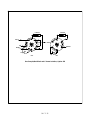
SVC 1- 13
AC POWER SUPPLY
REMOTE
START/STOP
ANALOG
SIGNAL 1
OUTPUT
KEYBOARD
AND
J1
DISPLAY
P1
P5
P6
P7
P8
F1
5A
250V
MAIN PCB
J1
J9
DETECTOR
A
J2
PCB
F3
5A
250V
P2
DETECTOR
B
J2
PCB
PRESSURE
CONTROL
PCB
ZONE
TEMP
SENSORS
&
INJECTION
PORT FAN
ANALOG
SIGNAL 2
OUTPUT
P4
J14
P3
J1
VALVE PCB
CRYO &
4 HEATED
ZONES
5th HEATED
ZONE &
VALVE 1 & 2
P13
COMMUNICATIONS
PCB
J12
ELECTRONIC
FLOW
SENSOR
OVEN
FLAP
STEPPER
MOTOR,
IGNITOR,
VLVA, VLVB
J1
P10
P12
P11
F2
5A
250V
TRANSFORMER
F4, F5
5A
250V
MAIN SWITCH
AC PCB
OVEN TRIAC
OVEN HEATER
OVEN FAN MOTOR
SVC 1- 14
LINE
CORD
Section 2
INLET COMPONENTS
REPLACING INLET COMPONENTS
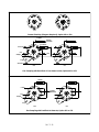
There are five inlet options available for the HP 5890 Series II Gas Chromatograph; packed column,
packed column with septum purge, split/splitless capillary, split- only capillary, and Programmable Cool
On- Column capillary (PCOC). Maintenance procedures for all the inlets are given in the following
pages. Procedures are supplied to remove, replace, and/or clean various subassemblies, based on the
current maintenance philosophy, i. e., to allow replacement of the lowest level components applicable
for a particular inlet.
Specific part numbers are not given in this section. For all replacement part numbers, refer to Section 5
of the IPB portion of this document (Inlet Components).
All of the inlets are heated using a heater/sensor setup which consists of at least one heater cartridge
and one sensor cartridge. Heating of the inlet zones is not covered in this section. For information on
the zone heater/sensor systems, refer to Section 6 of the service portion of this document (Zone Temperature).
This document is not meant to provide instruction for first time installation of the inlet options discussed.
Add- on sheets exist for just this purpose, and should be referenced when performing a first time installation.
TABLE OF CONTENTS
REPLACING INLET COMPONENTS . . . . . . . . . . . . . . . . . . . SVC 2- 1
PACKED COLUMN INLET . . . . . . . . . . . . . . . . . . . . . . . . . . . . SVC 2- 2
Remove/Replace Packed Column Inlet . . . . . . . . . . . . . . . . . . . . . . . . . . . . . SVC 2- 2
SEPTUM- PURGED PACKED COLUMN INLET . . . . . . . . . SVC 2- 5
Remove/Replace Septum- Purged Packed Column Inlet . . . . . . . . . . . . . SVC 2- 5
SPLIT- ONLY CAPILLARY INLET . . . . . . . . . . . . . . . . . . . . . SVC 2- 8
Remove/Replace Split- Only Capillary Inlet . . . . . . . . . . . . . . . . . . . . . . . . . SVC 2- 8
SPLIT/SPLITLESS CAPILLARY INLET . . . . . . . . . . . . . . . . . SVC 2- 12
Remove/Replace Split/Splitless Capillary Inlet . . . . . . . . . . . . . . . . . . . . . . . SVC 2- 12
PROGRAMMABLE COOL ON COLUMN INLET (PCOC) . SVC 2- 16
Remove/Replace PCOC Inlet . . . . . . . . . . . . . . . . . . . . . . . . . . . . . . . . . . . . . SVC 2- 16
INJECTION PORT COOLING FAN . . . . . . . . . . . . . . . . . . . . . SVC 2- 20
Remove/Replace Cooling Fan . . . . . . . . . . . . . . . . . . . . . . . . . . . . . . . . . . . . SVC 2- 20
SVC 2- 1
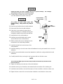
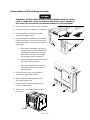
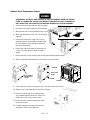
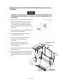
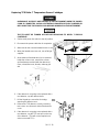
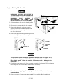
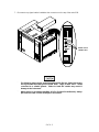
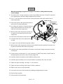
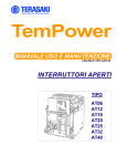
PACKED COLUMN INLET
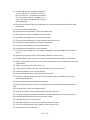
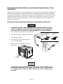
Remove/Replace Packed Column Inlet
HAZARDOUS VOLTAGES ARE PRESENT IN THE
INSTRUMENT WHEN THE POWER CORD IS
CONNECTED.
AVOID
A
POTENTIALLY
DANGEROUS
SHOCK
HAZARD
BY
DISCONNECTING THE POWER CORD BEFORE
WORKING ON THE INSTRUMENT.
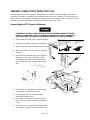
RED O VISIBLE
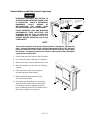
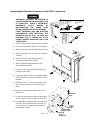
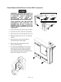
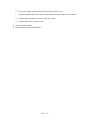
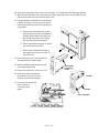
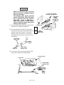
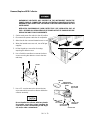
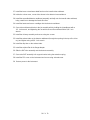
1. Set the main power line switch to the off position.
OFF
ON
2. Disconnect the power cable from its receptacle.
3. Allow time for the oven and heated zones to cool.
4. When the heated zones are cool, turn off all gas
supplies.
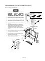
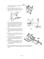
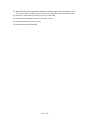
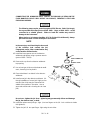
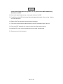
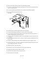
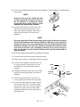
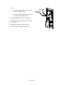
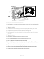
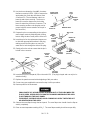
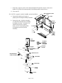
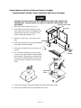
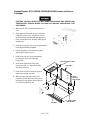
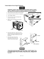
5. At the bottom of the inlet(s) to be removed, inside the column oven, remove the column and
hardware associated with the inlet(s) (liner,
column/liner nuts, ferrules, makeup gas adapter, etc.).
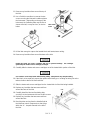
INJECTION PORT COVER
TOP COVER
6. Remove the injection port cover by grasping its
back edge and lifting it upward.
7. Remove the two screws securing the left side
panel along its bottom edge.
8. Slide the left side panel towards the
rear of the instrument and lift.
LID SHAFT
LEFT
SIDE
PANEL
1/4- INCH
SCREW
AND
WASHER
SCREWS
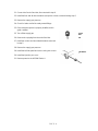
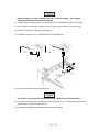
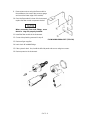
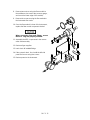
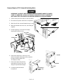
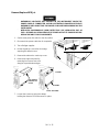
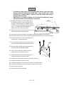
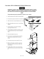
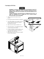
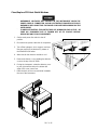
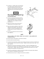
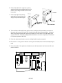
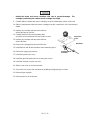
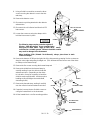
9. Disconnect the Carrier Gas Inlet which connects to a fitting either at the EFS, a chemical
filter, or a mass flow controller mounted on the
flow panel.
10. Inside the column oven, cap the base of the
inlet.
CARRIER
GAS
INLET
FITTING
SVC 2- 2
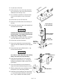
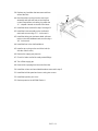
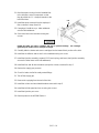
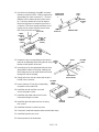
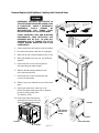
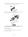
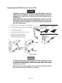
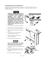
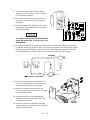
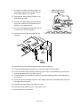
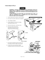
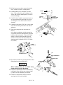
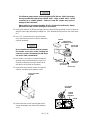
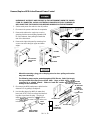
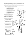
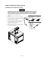
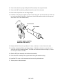
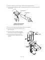
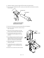
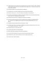
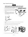
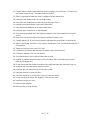
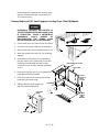
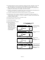
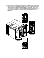
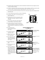
11. Remove any insulation from around the top of
the inlet.
12. Use a Pozidriv screwdriver to remove the two
screws securing the inlet and insulation plate to
the instrument. (Depending on the age of the
instrument, the insulation plate may be flat, as
shown at the left, or may be a box, as shown
below.
INSULATION
PLATE
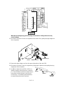
13. Lift the inlet enough to expose the heated block and heater/sensor wiring.
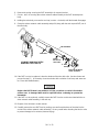
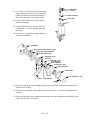
14. Remove any insulation from around the base of the inlet.
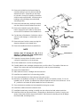
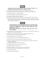
Handle the heater and sensor cartridges with care to prevent breakage. The cartridges
(particularly the smaller sensor cartridge) are fragile.
15. Carefully slide the heater and sensor cartridges out of the heated block portion of the inlet.
Use caution to avoid sharp bends when bending tubing. Sharp bends may crimp the tubing.
16. If the inlet is to be replaced, prepare the replacement inlet by pre- bending its tubing into orientations similar to that of the removed inlet.
17. Slide the heater and sensor cartridges into the heated block of the inlet being installed.
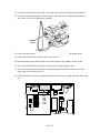
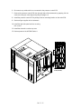
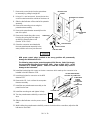
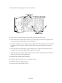
19. Replace any insulation that was removed from
around the base of the inlet.
18. Carefully install the inlet and insulation plate,
securing it to the instrument with two Pozidriv screws.
19. Replace any insulation that was removed from
around the inlet.
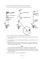
20. Bend the tube running from the installed inlet to
the inlet flow control components so that it lays
within the “U”- shaped channels to the left of
the inlet.
SVC 2- 3
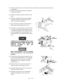
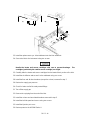
SLOTS
21. Connect the Carrier Gas Inlet, disconnected in step 9.
22. Install the liner and all other hardware (except the column) removed during step 5.
23. Restore the supply gas pressure.
24. Check for leaks at all of the newly mated fittings.
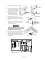
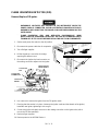
25. Ensure that the septum is properly installed, and in
good condition.
25. Turn off the supply gas.
SEPTUM NUT
ASSEMBLY
26. Remove the cap/plug from the end of the inlet.
SEPTUM
27. Install the column and associated hardware removed
in step 5.
28. Restore the supply gas pressure.
29. Install the left side panel and secure using two screws.
30. Install the injection port cover.
31. Restore power to the HP 5890 Series II.
SVC 2- 4
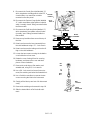
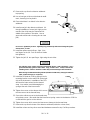
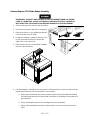
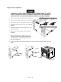
WELDMENT
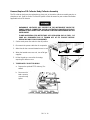
SEPTUM- PURGED PACKED COLUMN INLET
Remove/Replace Septum- Purged Packed Column Inlet
HAZARDOUS VOLTAGES ARE PRESENT IN
THE INSTRUMENT WHEN THE POWER CORD
IS CONNECTED. AVOID A POTENTIALLY
DANGEROUS
SHOCK
HAZARD
BY
DISCONNECTING THE POWER CORD
BEFORE WORKING ON THE INSTRUMENT.
RED O VISIBLE
1. Set the main power line switch to the off position.
OFF
ON
2. Disconnect the power cable from its receptacle.
3. Allow time for the oven and heated zones to cool.
4. When the heated zones are cool, turn off all gas
supplies.
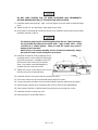
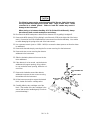
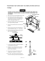
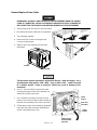
5. At the bottom of the inlet(s) to be removed, inside the column oven, remove the column and
hardware associated with the inlet(s) (liner,
column/liner nuts, ferrules, makeup gas adapter, etc.).
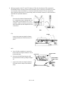
INJECTION PORT COVER
TOP COVER
6. Remove the injection port cover by grasping its
back edge and lifting it upward.
PRESS
HERE TO
FREE
COVER
7. Remove the two screws securing the left side
panel along its bottom edge.
8. Slide the left side panel towards the
rear of the instrument and lift.
LID SHAFT
LEFT
SIDE
PANEL
1/4- INCH
SCREW
AND
WASHER
SCREWS
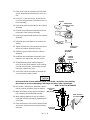
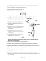
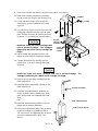
9. Disconnect the Carrier Gas Inlet (labelled “C”)
which connects to a fitting either at the EFS, or
at a mass flow controller mounted on the flow
panel.
10. Disconnect the Septum Purge Outlet (labelled
“P”) which connects to a pressure regulator
(“IN”fitting) mounted on the flow panel.
INJECTION
PORT
PURGE TUBE
SVC 2- 5
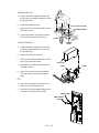
INJECTION
PORT
CARRIER
TUBE
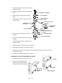
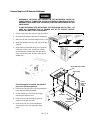
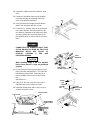
11. Cap the base of the inlet.
12. Remove the two screws in the top of the inlet
top cover (these screws secure the inlet base
weldment to the inlet top cover).
13. Use a Pozidriv screwdriver to remove the two
screws securing the top cover to the instrument.
14. Lift the inlet top cover off of the inlet.
15. Remove any insulation from around the top of
the inlet.
HEATER/SENSOR
CABLE ASSEMBLY
16. Lift the inlet enough to expose the heated block
and heater/sensor wiring.
Handle the heater and sensor cartridges with care to
prevent breakage. The cartridges (particularly the
smaller sensor cartridge) are fragile.
PURGED- PACKED
INLET WELDMENT
15. Carefully slide the heater and sensor cartridges
out of the heated block portion of the inlet.
16. Lift the inlet out of the instrument.
17. Remove the heated block and heated block
strap from the base weldment by removing two
screws.
BOTTOM
INSULATION
BOTTOM
INSULATION
COVER
SCREW
18. Remove the top insert weldment and o- ring
from the base weldment.
TOP INSERT
WELDMENT
HEATED BLOCK
STRAP
SCREW
Use caution to avoid sharp bends when bending
tubing. Sharp bends may crimp the tubing.
19. If the inlet base weldment is to be replaced,
prepare the replacement by pre- bending its
tubing into orientations similar to that of the removed inlet.
O- RING
20. Secure the heated block and heated block
strap to the base weldment using two screws.
21. Slide the heater and sensor cartridges into the
heated block of the inlet being installed.
22. Install the top insert weldment and associated
o- ring onto the base weldment, ensuring that
the o- ring is installed and seated properly.
SVC 2- 6
BASE WELDMENT
HEATED BLOCK
23. Carefully install the inlet into its inlet opening in the top of the instrument.
24. Replace any insulation that was removed from around the inlet.
25. Install the top cover over the inlet.
SLOTS
26. Secure the inlet to the top cover using two screws.
27. Secure the top cover and inlet to the instrument
using two screws.
28. Bend the tubes running from the installed inlet
to the inlet flow control components so that
they lay within the “U”- shaped channels to the
left of the inlets.
29. Install the tubes removed in steps 9 and 10.
30. Install the liner and all other hardware (except
the column) removed in step 5.
31. Loosen the two screws securing the bottom
insulation cover, inside the column oven.
BOTTOM
INSULATION
32. Rotate the bottom insulation cover to free it and
the bottom insulation from the wall of the column oven.
BOTTOM
INSULATION
COVER
SCREW
33. Inspect the insulation to ensure that it is in
good condition. Replace if required.
34. Install the bottom insulation and bottom insulation
cover on the column oven wall.
35. Tighten the two screws securing the bottom insulation
cover to the column oven wall.
36. Remove the septum nut assembly from the top insert
weldment.
37. Inspect the septum to insure that it is properly
installed and in good condition. Replace if
required.
SEPTUM NUT
ASSEMBLY
SEPTUM
38. Install the septum nut assembly.
39. Restore the supply gas pressure.
40. Check for leaks at all of the newly mated fittings.
41. Turn off the supply gas.
42. Remove the cap/plug from the end of the inlet.
43. Install the column and associated hardware
removed in step 5.
44. Install the left side panel and secure using two screws.
45. Install the injection port cover.
46. Restore power to the HP 5890 Series II.
SVC 2- 7
TOP INSERT
WELDMENT
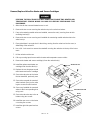
SPLIT- ONLY CAPILLARY INLET
Remove/Replace Split- Only Capillary Inlet
HAZARDOUS VOLTAGES ARE PRESENT IN THE
INSTRUMENT WHEN THE POWER CORD IS
CONNECTED.
AVOID
A
POTENTIALLY
DANGEROUS
SHOCK
HAZARD
BY
DISCONNECTING THE POWER CORD BEFORE
WORKING ON THE INSTRUMENT.
1. Set the main power line switch to the off position.
RED O VISIBLE
OFF
ON
2. Disconnect the power cable from its receptacle.
3. Allow time for the oven and heated zones to cool.
4. When the heated zones are cool, turn off all gas
supplies.
5. At the bottom of the inlet(s) to be removed, inside the column oven, remove the column and
hardware associated with the inlet(s) (liner,
column/liner nuts, ferrules, makeup gas adapter, etc.).
6. Remove the injection port cover by grasping its
back edge and lifting it upward.
7. Remove the two screws securing the left side
panel along its bottom edge.
8. Slide the left side panel towards the
rear of the instrument and lift.
INJECTION PORT COVER
TOP COVER
PRESS
HERE TO
FREE
COVER
LID SHAFT
LEFT
SIDE
PANEL
1/4- INCH
SCREW
AND
WASHER
SCREWS
SVC 2- 8
9. Disconnect the Carrier Gas Inlet (labelled “C”)
which terminates at a fitting either at the EFS, a
chemical filter, or a mass flow controller
mounted on the flow panel.
10. Disconnect the Septum Purge Outlet (labelled
“P”) which terminates at the splitless solenoid
valve (“normally closed”fitting) mounted inside
the flow module.
SPLIT
VENT
CARRIER
11. Disconnect the Split Vent Outlet (labelled “S”)
which terminates at a splitless solenoid valve
(normally “open”fitting) mounted inside the
flow module.
SHELL WELDMENT
SEPTUM
PURGE
INSERT
ASSEMBLY
12. Remove any insulation from around the top of
the inlet.
13. Detach and remove the insert assembly from
the shell weldment using a ???- inch wrench.
14. Detach and remove the tubing nut from the fitting on the shell weldment.
15. Loosen the two screws securing the insulation
cover inside the column oven.
16. Rotate the cover, freeing it from its securing
hardware, and remove the cover and three
pieces of lower insulation.
RETAINING
NUT
17. Remove the reducing nut, flat washer, and
anealed seal, using a 1/2- inch wrench.
18. Use a 3/4- inch wrench to loosen (but not remove) the retaining nut below the heated block.
19. Use a Pozidriv screwdriver to remove the two
screws securing the inlet to the instrument.
20. Gently pull the inlet up and out of its instrument
cavity.
21. Remove the retaining nut loosened in step 18.
22. Slide the heated block off of the shell weldment.
SVC 2- 9
FLAT
WASHER
REDUCING
NUT
LOWER
INSULATION
LOWER
INSULATION
COVER
Handle the heater and sensor cartridges with care to prevent breakage. The cartridges
(particularly the smaller sensor cartridge) are fragile.
23. Carefully slide the heater and sensor cartridges
out of the heated block portion of the inlet.
HEATER/SENSOR
CABLE ASSEMBLY
LINER
Use caution to avoid sharp bends when
bending tubing. Sharp bends may crimp the
tubing.
SHELL
WELDMENT
24. Remove any insulation from the shell weldment.
25. Remove the liner from the shell weldment.
26. If the inlet is to be replaced, prepare the replacement inlet by pre- bending its tubing into
orientations similar to that of the removed inlet.
27. Install the liner in the shell weldment.
HEATED
BLOCK
28. Install any removed insulation which wraps
around the tube in the shell weldment.
30. Slide the heater and sensor cartridges into the
heated block of the inlet being installed.
RETAINING
NUT
31. Install the heated block onto the stem of the
shell weldment.
32. Install the retaining nut on the base of the shell weldment securing the heated block to the shell
weldment.
33. Install any removed insulation around the heated block (within the cavity provided in the shell
weldment).
34. Carefully install the inlet, securing it to the instrument with two Pozidriv screws.
NOTE
To lessen the possibility of pressure leaks, always install a new anealed seal, when the old seal
has been removed.
35. Tighten the retaining nut at the base of the shell weldment.
36. Install the reducing nut, flat washer, and anealed seal onto the base of the retaining nut.
37. Install the lower insulation cover and three pieces of lower insulation, inside the column oven.
38. Tighten the two screws which secure the lower insulation cover inside the column oven.
SVC 2- 10
39. Replace any insulation that was removed from
around the inlet.
40. Bend the tubes running from the new insert
assembly and split vent tube to the inlet flow
control components so that they lay within the
“U”- shaped channels to the left of the inlets.
41. Install the tubes removed in steps 9 through 11.
42. Install the insert assembly on the shell weldment and secure using a ???- inch wrench.
43. Install the tubing nut (and associated split vent
tube) on the shell weldment and secure using a
1/2- inch wrench.
44. Install the liner in the shell weldment.
45. Install a cap or plug on the end of the inlet (inside the column oven).
46. Restore the supply gas pressure.
47. Check for leaks at all of the newly mated fittings.
48. Turn off the supply gas.
49. Remove the cap/plug from the end of the inlet.
50. Install the column and associated hardware removed in step 5.
51. Install the left side panel and secure using two screws.
52. Install the injection port cover.
53. Restore power to the HP 5890 Series II.
SVC 2- 11
SLOTS
SPLIT/SPLITLESS CAPILLARY INLET
Remove/Replace Split/Splitless Capillary Inlet
HAZARDOUS VOLTAGES ARE PRESENT IN THE
INSTRUMENT WHEN THE POWER CORD IS
CONNECTED.
AVOID
A
POTENTIALLY
DANGEROUS
SHOCK
HAZARD
BY
DISCONNECTING THE POWER CORD BEFORE
WORKING ON THE INSTRUMENT.
1. Set the main power line switch to the off position.
RED O VISIBLE
OFF
ON
2. Disconnect the power cable from its receptacle.
3. Allow time for the oven and heated zones to cool.
4. When the heated zones are cool, turn off all gas
supplies.
5. At the bottom of the inlet(s) to be removed, inside the column oven, remove the column and
hardware associated with the inlet(s) (liner,
column/liner nuts, ferrules, makeup gas adapter, etc.).
6. Remove the injection port cover by grasping its
back edge and lifting it upward.
7. Remove the two screws securing the left side
panel along its bottom edge.
8. Slide the left side panel towards the
rear of the instrument and lift.
INJECTION PORT COVER
TOP COVER
PRESS
HERE TO
FREE
COVER
LID SHAFT
LEFT
SIDE
PANEL
1/4- INCH
SCREW
AND
WASHER
SCREWS
SVC 2- 12
9. Disconnect the Carrier Gas Inlet (labelled “C”)
which terminates at a fitting either at the EFS, a
chemical filter, or a mass flow controller
mounted on the flow panel.
10. Disconnect the Septum Purge Outlet (labelled
“P”) which terminates at the splitless solenoid
valve (“normally closed”fitting) mounted inside
the flow module.
SEPTUM
PURGE
SPLIT
VENT
11. Disconnect the Split Vent Outlet (labelled “S”)
which terminates at a splitless solenoid valve
(normally “open”fitting) mounted inside the
flow module.
CARRIER
GAS
SHELL WELDMENT
INSERT
ASSEMBLY
12. Remove any insulation from around the top of
the inlet.
13. Detach and remove the insert assembly from
the shell weldment using a ???- inch wrench.
14. Detach and remove the tubing nut from the fitting on the shell weldment.
15. Loosen the two screws securing the insulation
cover inside the column oven.
16. Rotate the cover, freeing it from its securing
hardware, and remove the cover and three
pieces of lower insulation.
RETAINING
NUT
17. Remove the reducing nut, flat washer, and
anealed seal, using a 1/2- inch wrench.
18. Use a 3/4- inch wrench to loosen (but not remove) the retaining nut below the heated block.
19. Use a Pozidriv screwdriver to remove the two
screws securing the inlet to the instrument.
20. Gently pull the inlet up and out of its instrument
cavity.
21. Remove the retaining nut loosened in step 18.
22. Slide the heated block off of the shell weldment.
SVC 2- 13
FLAT
WASHER
REDUCING
NUT
LOWER
INSULATION
LOWER
INSULATION
COVER
Handle the heater and sensor cartridges with care to prevent breakage. The cartridges
(particularly the smaller sensor cartridge) are fragile.
23. Carefully slide the heater and sensor cartridges
out of the heated block portion of the inlet.
HEATER/SENSOR
CABLE ASSEMBLY
LINER
Use caution to avoid sharp bends when
bending tubing. Sharp bends may crimp the
tubing.
SHELL
WELDMENT
24. Remove any insulation from the shell weldment.
25. Remove the liner from the shell weldment.
26. If the inlet is to be replaced, prepare the replacement inlet by pre- bending its tubing into
orientations similar to that of the removed inlet.
27. Install the liner in the shell weldment.
HEATED
BLOCK
28. Install any removed insulation which wraps
around the tube in the shell weldment.
30. Slide the heater and sensor cartridges into the
heated block of the inlet being installed.
RETAINING
NUT
31. Install install the heated block onto the stem of
the shell weldment.
32. Install the retaining nut on the base of the shell weldment securing the heated block to the shell
weldment.
33. Install any removed insulation around the heated block (within the cavity provided in the shell
weldment).
34. Carefully install the inlet, securing it to the instrument with two Pozidriv screws.
NOTE
To lessen the possibility of pressure leaks, always install a new anealed seal, when the old seal
has been removed.
35. Tighten the retaining nut at the base of the shell weldment.
36. Install the reducing nut, flat washer, and anealed seal onto the base of the retaining nut.
37. Install the lower insulation cover and three pieces of lower insulation, inside the column oven.
38. Tighten the two screws which secure the lower insulation cover inside the column oven.
SVC 2- 14
39. Replace any insulation that was removed from
around the inlet.
40. Bend the tubes running from the new insert
assembly and split vent tube to the inlet flow
control components so that they lay within the
“U”- shaped channels to the left of the inlets.
41. Install the tubes removed in steps 9 through 11.
42. Install the insert assembly on the shell weldment and secure using a ???- inch wrench.
43. Install the tubing nut (and associated split vent
tube) on the shell weldment and secure using a
1/2- inch wrench.
44. Install the liner in the shell weldment.
45. Install a cap or plug on the end of the inlet (inside the column oven).
46. Restore the supply gas pressure.
47. Check for leaks at all of the newly mated fittings.
48. Turn off the supply gas.
49. Remove the cap/plug from the end of the inlet.
50. Install the column and associated hardware removed in step 5.
51. Install the left side panel and secure using two screws.
52. Install the injection port cover.
53. Restore power to the HP 5890 Series II.
SVC 2- 15
SLOTS
PROGRAMMABLE COOL ON COLUMN INLET (PCOC)
Remove/Replace PCOC Inlet
HAZARDOUS VOLTAGES ARE PRESENT IN THE
INSTRUMENT WHEN THE POWER CORD IS
CONNECTED.
AVOID
A
POTENTIALLY
DANGEROUS
SHOCK
HAZARD
BY
DISCONNECTING THE POWER CORD BEFORE
WORKING ON THE INSTRUMENT.
1. Set the main power line switch to the off position.
RED O VISIBLE
OFF
ON
2. Disconnect the power cable from its receptacle.
3. Allow time for the oven and heated zones to cool.
4. When the heated zones are cool, turn off all gas
supplies.
5. At the bottom of the inlet(s) to be removed, inside the column oven, remove the column and
hardware associated with the inlet(s) (liner,
column/liner nuts, ferrules, makeup gas adapter, etc.).
6. Remove the injection port cover by grasping its
back edge and lifting it upward.
7. Remove the two screws securing the left side
panel along its bottom edge.
8. Slide the left side panel towards the
rear of the instrument and lift.
INJECTION PORT COVER
TOP COVER
PRESS
HERE TO
FREE
COVER
LID SHAFT
LEFT SIDE
PANEL
1/4- INCH
SCREW
AND
WASHER
SCREWS
SVC 2- 16
9. Disconnect the Carrier Gas Inlet which terminates either at the Forward Pressure Regulator
(for Manual Pressure Control) or the PCOC Proportional Control Valve (for Electronic Pressure
Control).
10. Disconnect the Septum Purge Outlet which terminates at the PCOC Purge Regulator,
mounted inside the flow module.
11. Cap the base of the inlet, inside the column
oven.
12. Remove the auto- injection assembly (or optional manual injection assembly) by rotating it
counter- clockwise). Be careful not to loose
the septum, insert, or PCOC insert spring which
are installed under the injection assembly.
AUTO
INJECTION
ASSEMBLY
OPTIONAL
MANUAL
INJECTION
ASSEMBLY
DUCKBILL
SEPTUM
SEPTUM
INSERT
HEATER/SENSOR
CABLE ASSEMBLY
PCOC INSERT
SPRING
AIR DEFLECTOR
WELDMENT
INSULATION
CAVITY
SLEEVE
SCREW
13. Remove the air deflector using a Pozidriv screwdriver to remove the screw securing the air deflector to the inlet weldment.
SVC 2- 17
Handle the heater and sensor cartridges with care to prevent breakage.
(particularly the smaller sensor cartridge) are fragile.
The cartridges
14. Carefully slide the heater and sensor cartridges out of the heated block portion of the inlet.
15. Use a Pozidriv screwdriver to remove the two screws securing the inlet to the instrument.
16. Lift the inlet enough to expose the heated block.
17. If installed, remove the cryo- blast tube from the inlet weldment.
(a)
(b)
18. Remove any insulation from around the inlet.
Use caution to avoid sharp bends when bending tubing. Sharp bends may crimp the tubing.
19. If the inlet is to be replaced, prepare the replacement inlet by pre- bending its tubing into orientations similar to that of the removed inlet.
20. Replace any insulation that was removed from around the inlet.
SVC 2- 18
21. Bend the tubes running from the installed inlet
to the inlet flow control components so that
they lay within the “U”- shaped channels to the
left of the inlets.
22. Install the tubes removed from the employed
flow controller in steps 9 and 10.
SLOTS
23. If employed, install the cryo- blast weldment
onto the inlet weldment.
24. Secure the inlet to the instrument using two
screws.
Handle the heater and sensor cartridges with care to prevent breakage.
(particularly the smaller sensor cartridge) are fragile.
The cartridges
25. Carefully slide the heater and sensor cartridges into the heated block portion of the inlet.
26. Install the air deflector and secure it to the weldment using one screw.
27. Install the injection assembly, septum,PCOC insert spring, and insert (the injection assembly
secures the other items to the inlet weldment).
28. Install the liner and all other hardware (except the column) removed in step 5.
29. Restore the supply gas pressure.
30. Check for leaks at all of the newly mated fittings.
31. Turn off the supply gas.
32. Remove the cap/plug from the end of the inlet.
33. Install the column and associated hardware removed in step 5.
34. Install the left side panel and secure using two screws.
35. Install the injection port cover.
36. Restore power to the HP 5890 Series II.
SVC 2- 19
INJECTION PORT COOLING FAN
Remove/Replace Cooling Fan
HAZARDOUS VOLTAGES ARE PRESENT IN THE INSTRUMENT WHEN THE POWER CORD IS
CONNECTED. AVOID A POTENTIALLY DANGEROUS SHOCK HAZARD BY DISCONNECTING
THE POWER CORD BEFORE WORKING ON THE INSTRUMENT.
1. Set the main power line switch to the off position.
RED O VISIBLE
2. Disconnect the power cable from its receptacle.
NOTE
If an autosampler is installed, the injection
port cover will not be present.
OFF
ON
3. Remove the injection port cover by grasping its
back edge and lifting it upward.
4. If an autosampler is installed on the instrument,
it will be necessary to remove it and its mounting bracket to allow removal of the left side cover as follows:
a. Remove the autosampler tray from its
mounting bracket by first simultaneously lifting and turning the two tray locks
which hold it in position, then sliding
the tray away from the instrument.
INJECTION PORT COVER
TOP COVER
b. Lift the autosampler tray from its mounting bracket and set it aside.
c. Remove the autosampler bracket by
removing the 6 screws securing it to
the instrument.
PRESS
HERE TO
FREE
COVER
LID SHAFT
1/4- INCH
SCREW
AND WASHER
SVC 2- 20
5. Remove the electronics carrier top cover .
SCREWS
6. Remove the right side panel by
removing four screws: two each
along its top and bottom edges.
7. Remove the back cover of the
instrument by removing four
screws and sliding the cover
off of the rear of the instrument.
ELECTRONICS
CARRIER TOP
COVER
RIGHT SIDE PANEL
8. Remove the PCOC fan cover by
removing the two screws securing it to the instrument. (Removal of the fan cover frees the
fan.)
SCREW
9. Trace the fan power wires to there destination
at connector P7 on the main PCB (exposed
right side of instrument).
COOLING
FAN
FAN
SHROUD
WHEN DISCONNECTING A PLUG, PULL ON
THE PLUG NOT ON ITS WIRES. PULLING ON
THE WIRES MAY CAUSE BREAKAGE.
10. Disconnect connector P7 from its receptacle by
pulling it straight off. (Heated zones corresponding to sensor lead locations are labeled
to the right of the P7 connector receptacle on
the main PCB.)
1
3
5
7
9
11
13
2
4
6
8
10
12
14
P7 -
C10
OVEN
DETA
DETB
INJA
INJB
AUX
FAN+
SCREWS
P7
C9
Q3
Q6
SVC 2- 21
FLOW
DIRECTION
ARROW
11. Use the lance release tip of an AMP pin extraction/lance reset tool (8710- 1542) to remove the
appropriate pins from connector P7. (The tool
features a lance release tip and a lance reset
tip. The lance release tip is used to depress
the pin locking lance to extract the pin from a
connector. The lance reset tip positions a locking lance to its proper height to ensure retention of the pin in the connector.)
TOOL STOP
LANCE
RELEASE
TIP
TOOL
STOP
EXTRACTION
LANCE RESET
TOOL
LANCE
RELEASE
TIP
LANCE
RESET TIP
DASH NUMBER
MARKED HERE
INSERT TIP
HERE
(BACK OF
CAVITY)
LOCKING
LANCE
CAVITY
BACK OF
HOUSING
CONTACT
(TYPICAL)
12. Prepare the pins corresponding to the replacement fan by adjusting their locking lances using
the lance reset portion of the tool.
TAPER
LANCE
RESET
TIP
13. Insert the pins for the replacement fan into their
appropriate locations in the plug, making sure
the locking lance on each pin seats into its hole
through the side of the plug.
RECEPTACLE
BOX (TYPICAL)
14. Gently pull on the wire to ensure that the pin is
locked in the connector.
15. Insert connector P7 into its corresponding
receptacle on the main PCB.
LOCKING
LANCE
LOCKING
LANCE
CAVITY
LOCKING
LANCE
16. Install the new fan and fan cover and
secure using two screws.
17. Install the rear panel and secure it to the
instrument using four screws.
CONTACT
(TYPICAL)
BACK OF
HOUSING
18. Install the right side panel and secure using
four screws.
19. Install the electronics carrier top cover.
20. If removed, install autosampler and associated bracketry.
21. Install the injection port cover.
22. Restore power to the instrument.
SVC 2- 22
Section 3
FLOW/PRESSURE CONTROL
COMPONENTS
FLOW/PRESSURE CONTROL COMPONENTS
Flow and pressure control components include pressure regulators, pressure gauges, mass flow controllers, capillary solenoid valves, detector flow manifold blocks, and the Electronic Flow Sensor (EFS)
module. There are many options available for the HP 5890 Series II. Maintenance procedures for the
most common items found in the instrument. Procedures are supplied to remove, replace, and/or
clean various subassemblies, based on the current maintenance philosophy, i. e., to allow replacement
of the lowest level components applicable for a particular assembly.
Specific part numbers are not given in this section. For all replacement part numbers, refer to Sections
3 and 4 of the IPB portion of this document (Detector Flow Manifold Assemblies and Injection Port Flow/
Pressure Control Modules, respectively).
This document is not meant to provide instruction for first time installation of any of the options discussed. Add- on sheets exist for just this purpose, and should be referenced when performing a first
time installation.
TABLE OF CONTENTS
FLOW/PRESSURE CONTROL COMPONENTS . . . . . . . . . SVC 3- 1
PCOC EPC/MPC Troubleshooting . . . . . . . . . . . . . . . . . . . . . . . . . . . . . . . . SVC 3Remove/Replace Inlet Flow Control Components. . . . . . . . . . . . . . . . . . . . SVC 3Remove/Replace Split/Splitless Capillary Inlet Solenoid Valve . . . . . . . . . SVC 3Remove/Replace Electronic Pressure Control (EPC) Components . . . . . SVC 3Remove/Replace Manual Pressure Control (MPC) Components . . . . . . . SVC 3Remove/Replace EPC/MPC Pressure Control PCB . . . . . . . . . . . . . . . . . . SVC 3Typical Switch Settings for EPC/MPC PCBs . . . . . . . . . . . . . . . . . . . . . . . . . SVC 3Replace Electronic Flow Sensor Module . . . . . . . . . . . . . . . . . . . . . . . . . . . SVC 3Electronic Flow Sensor (EFS) Calibration . . . . . . . . . . . . . . . . . . . . . . . . . . . SVC 3Setting the ZERO Calibration Value . . . . . . . . . . . . . . . . . . . . . . . . . . . . . . . . SVC 3Setting the GAIN Calibration Value . . . . . . . . . . . . . . . . . . . . . . . . . . . . . . . . SVC 3Entering Specific ZERO and GAIN Values . . . . . . . . . . . . . . . . . . . . . . . . . . SVC 3Replacing/Repairing a Flow Manifold Block . . . . . . . . . . . . . . . . . . . . . . . . . SVC 3-
SVC 3- 1
2
5
7
11
14
17
18
19
22
22
23
24
2 5
PCOC EPC/MPC TROUBLESHOOTING
The Programmable Cool On Column (PCOC) injection port is designed to allow the injection syringe to
admit sample directly into the capillary column(320, 200, 100 micron id). This is accomplished by the
use of an insert which serves to align the syringe with the capillary column and make a seal with both
the column and the syringe needle. Maximum sample volumes are smaller compared with other inlets,
typically in the range of 0.5 microlitre to 2.0 microlitre. The ideal volume depends on the column id, the
compatibility of the sample solvent and the stationary phyase, sample concentration, stationary phase
film thickness, and column flow rate. Usually the smaller the sample the better, providing that sensitivity
requirements are met.
The Programmable Cool On Column injection port operates by forward pressure control of the inlet and
the inclusion of a preset foward pressure contolled septum purge vent carries septum bleed out to vent.
A typical example of pressure setting and associated flows would be: 50psi for the carrier with a setting
of 10 to 20psi in the injection port. This will also yeild a 10 to 20 ml/min septum purge vent flow.
Expected ranges of operation follow:
Temperature Control
Range: Ambient +4 Degrees C to 450 Degrees C
Temperature Programming: 0 to 100 Degrees c/minute
Typical Cooling Rate:
oven fan only(Standard) 10.5 mins
CO2 Cryo Blast
7.5 mins
LN2 Cryo Blast
4.5 mins
Oven Track Mode(Standard): Injection prot temperature is adjusted real time to lead oven temperature
program by 3 Degrees C.
Pressure Control
Range:
1 to 100 psi
Flow range(dependent on column): 10- 250 ml/min
Pressure Programming: 0.01 to 99psi/minute
Retention Time Reproducibility
0.001 - 0.004 minutes.*
*Average performance for C10 - C40 hydrocarbon mixture.
0.001 - 0.002 minute
Repeatability of Set Point Values <0.050psi(0.35kPa)
Stability over 72 hours
<0.060 psi (0.42kPa)
Pressure Noise (high frequency)
<0.025psi (0.17kPa)
Average Linearity(2- 80psi)
<0.100psi (0.7kPa)
Midrange Accuracy(20- 40psi)
<0.050psi(0.35kPa)
Pressure recovery after system disturbance
Repeatability of set point value agter septum change and 5- minute equilibration
1. Manual Pressure Control: 0.1- 0.2psi(0.7- 1.4kPa)
Electronic Pressure Control: 0.050psi(0.35kPa)
Manual Pressure Control
1 minute to 99%
12 hours to 100%
SVC 3- 2
Most compounds
Electronic Pressure Control
1 second to 99%
Safety Shutdown (Standard): If the system is unable to reach or maintain pressure set point value after
45 seconds the following 3 things happen. The alarm relay is triggered and the alarm sounds immediately. Pressure Control Valve shuts off all but a few ml/min of flow (bypass flow still permitted). The
oven and all heated zones are shut down.
This is a Fatal Error. The only way to recover is to power cycle the GC. If the leak has not been fixed,
the same sequence will repeat.
The Column head pressure may be controlled by either of two systems, Manual Presure Control (MPC)
or Electronic Pressure Control (EPC)
The MPC in an uncomplicated system consisting of 1) a manually adjustable forward pressure regulator
which sets the pressure in the inlet and 2) a factory preset forward pressure regulator allowing 10 to 20
ml/min to escape to vent pulling septum bleed with it.
Possible failures could include pluged restrictor in the inlet to the FPR. This would prevent the inlet from
reaching pressure setpoint. The FPR could be stuck open allowing the injection port to go to the same
pressure as the source gas tank. It could be stuck in the closed position preventing the injection point
from reaching the setpoint. Leaks in any of the tubing connections would also prevent the injection port
from reaching or maintaining pressure setpoint. Leaks at the Septum, Column fitting, Septum Purge
Control, Column Head Pressure gage or Purge Vent restrictor could also make injection port pressure
control difficult. These leaks should be checked by capping off the injection port or suspected part to
isolate it rather then using soap solution leak detection fluid.
The EPC uses a digitally controlled proportional control valve and electronic presssure transducer to
perform the same functions as the MPC’
s manual forward pressure control and column head pressure
gage. One additional feature of the EPC is a bypass flow line designed to protect the column with a
small flow (.1 to 3 ml/min) in the event that the proportional control valve or electronics would fail. The
same plugging or leak considerations as the MPC apply with the addition of the possiblity of electronic
failures to either the proportional valve, pressure transducer or electronic control board. These will be
verified by substitution.
Symptoms and possible causes
Not enough pressure.
1. Septum leaks or is missing
2. Column is broken
3. Column ferrule seal leaks
4. Gas supply is off
5. Supply pressure may not be achieveable with the column is use.
Pressure goes to 0 or max.
1. Configuration is wrong
Not Ready light flickers
(oscillating pressure)
1. Septum and/or column connection leaks.
2. Pressure set higher than the operating limit
SVC 3- 3
Not Ready light flickers
(oscillating temperature)
1. Configuration is wrong
2. Inlet temperature equilibration time too short.
Pressure and Temperature are not controllable
Configuration is wrong
No flow and high zero
1. Pressure transducer probably defective.
Background Zero <6psi
1. Possible problem with either EPC pressure transducer or EPC control bd.
SVC 3- 4
Remove/Replace Inlet Flow Control Components
`
HAZARDOUS VOLTAGES ARE PRESENT IN
THE INSTRUMENT WHEN THE POWER CORD
IS CONNECTED. AVOID A POTENTIALLY
DANGEROUS
SHOCK
HAZARD
BY
DISCONNECTING THE POWER CORD
BEFORE WORKING ON THE INSTRUMENT.
`
FLAME IONIZATION (FID) AND NITROGEN
PHOSPHOROUS (NPD) DETECTORS USE
HYDROGEN GAS AS FUEL. BE SURE ALL
HYDROGEN GAS IS TURNED OFF AT ITS
SOURCE BEFORE REPLACING ANY FLOW
COMPONENTS.
RED O VISIBLE
OFF
NOTE
This procedure applies to the packed, purged packed, split/splitless, and split only
inlets. Separate procedures exist for removal/replacement of the PCOC Electronic
Pressure Control (EPC) flow module and the PCOC Manual Pressure Control (MPC)
flow module. A separate procedure also exists for replacement of the split/splitless
capillary inlet solenoid valve.
1. Set the main power line switch to the off position.
2. Disconnect the power cable from its receptacle.
3. Allow time for the oven and heated zones to cool.
4. When the heated zones are cool, turn off all gas
supplies.
6. Remove the two screws securing the left
side panel along its bottom edge.
7. Slide the left side panel towards the rear
of the instrument and lift.
8. Disconnect plumbing fittings as necessary to
remove the flow module from the instrument.
(The hydrogen lines are painted red at their
ends. Remember which line is installed at each
fitting; draw a diagram if necessary.)
SVC 3- 5
ON
9. Remove two nuts securing the flow module to
the mainframe (one next to the pressure gauge,
and one at the lower edge of the module).
10. Once the flow module is clear of the instrument,
replace the flow control component desired.
When connecting lines and fittings, ensure
that all o- rings are properly installed.
11. Install the flow module in the instrument.
12. Connect the plumbing removed in step 8.
13. Restore all gas supplies.
FLOW MODULE BRACKET (TYPICAL)
14. Leak check all installed fittings.
15. If the system is leak- free, install the left side panel and secure using two screws.
16. Restore power to the instrument.
SVC 3- 6
Remove/Replace Split/Splitless Capillary Inlet Solenoid Valve
`
HAZARDOUS VOLTAGES ARE PRESENT IN
THE INSTRUMENT WHEN THE POWER CORD
IS CONNECTED. AVOID A POTENTIALLY
DANGEROUS
SHOCK
HAZARD
BY
DISCONNECTING THE POWER CORD
BEFORE WORKING ON THE INSTRUMENT.
`
FLAME IONIZATION (FID) AND NITROGEN
PHOSPHOROUS (NPD) DETECTORS USE
HYDROGEN GAS AS FUEL. BE SURE ALL
HYDROGEN GAS IS TURNED OFF AT ITS
SOURCE BEFORE REPLACING ANY FLOW
COMPONENTS.
RED O VISIBLE
OFF
ON
1. Set the main power line switch to the off position.
2. Disconnect the power cable from its receptacle.
3. Allow time for the oven and heated zones to cool.
4. When the heated zones are cool, turn off all gas
supplies.
5. Remove the two screws securing the left
side panel along its bottom edge.
6. Slide the left side panel towards the rear
of the instrument and lift.
7. Remove the four screws securing the rear
cover to the instrument.
8. Slide the rear cover towards the rear of the instrument.
9. Remove the electronics carrier top cover
(above the signal cable plugs and receptacles
to expose the top edge of the
TCD detector PCB).
10. Remove the right side panel by
removing four screws: two each
along its top and bottom edges.
SCREWS
ELECTRONICS
CARRIER TOP
COVER
SCREWS
SCREWS
RIGHT SIDE PANEL
SCREWS
SVC 3- 7
11. Locate the solenoid valve (on the flow control bracket at the lower left side of the instrument).
12. Disconnect all plumbing from the solenoid valve. (Label the tubes, noting the valve fittings to
which they connect, to facilitate easy assembly.
SOLENOID
VALVE
13. Loosen the two screws securing the solenoid valve to the flow control mounting bracket
14. Remove the solenoid valve from the flow control bracket.
15. Install the replacement solenoid valve in the same location and orientation as the old one.
16. Secure the solenoid valve to the flow control bracket by tightening two screws.
17. Trace and free the solenoid valve electrical leads along their path to the P8 connector at the
upper right corner of the main PCB.
18. Route the leads for the new solenoid valve along the same path, securing them with plastic wire
ties.
C10
2
4
6
8
10
12
14
1
3
5
7
9
11
13
P7
C9
IGN
VLVA
VLVB
FLAP
FLAP
FLAP
Q3
P8
Q6
SVC 3- 8
When removing a connector from a receptacle, pull on the connector not on its wires.
Pulling on the wires may cause breakage.
19. Disconnect connector P8 from its associated connector on the main PCB by pulling it straight
out.
20. The solenoid valve leads are connected to either the VLVA or VLVB outputs of connector P8.
Use the lance release tip of an AMP pin extraction/lance reset tool (8710- 1542) to remove the
appropriate pins from connector P8. (The tool
features a lance release tip and a lance reset
tip. The lance release tip is used to depress
the pin locking lance to extract the pin from a
connector. The lance reset tip positions a locking lance to its proper height to ensure retention of the pin in the connector.)
TOOL STOP
LANCE
RELEASE
TIP
EXTRACTION
LANCE RESET
TOOL
TOOL
STOP
LANCE
RELEASE
TIP
LANCE
RESET TIP
DASH NUMBER
MARKED HERE
INSERT TIP
HERE
(BACK OF
CAVITY)
LOCKING
LANCE
CAVITY
BACK OF
HOUSING
CONTACT
(TYPICAL)
21. Prepare the pins corresponding to the replacement sensor cartridges by adjusting their locking lances using the lance reset portion of the
tool.
22. Insert the pins for the replacement sensor into
their appropriate locations in the plug, making
sure the locking lance on each pin seats into its
hole through the side of the plug.
LOCKING
LANCE
CAVITY
LOCKING
LANCE
CONTACT
(TYPICAL)
BACK OF
HOUSING
SVC 3- 9
LANCE
RESET
TIP
TAPER
RECEPTACLE
BOX (TYPICAL)
LOCKING
LANCE
23. Gently pull on the wire to ensure that the pin is locked in the connector.
24. Insert connector P8 into its receptacle by pressing it straight in until it bottoms.
When connecting lines and fittings, ensure that all o- rings are properly installed.
25. Connect the plumbing to the new valve.
26. Restore gas supplies to the instrument.
27. Check for leakage at all installed fittings.
28. If the system is leak- free, verify operation of the split/splitless system by operating the solenoid
valve via the keyboard.
SVC 3- 10
Remove/Replace Electronic Pressure Control (EPC) Components
`
HAZARDOUS VOLTAGES ARE PRESENT IN
THE INSTRUMENT WHEN THE POWER CORD
IS CONNECTED. AVOID A POTENTIALLY
DANGEROUS
SHOCK
HAZARD
BY
DISCONNECTING THE POWER CORD
BEFORE WORKING ON THE INSTRUMENT.
`
FLAME IONIZATION (FID) AND NITROGEN
PHOSPHOROUS (NPD) DETECTORS USE
HYDROGEN GAS AS FUEL. BE SURE ALL
HYDROGEN GAS IS TURNED OFF AT ITS
SOURCE BEFORE REPLACING ANY FLOW
COMPONENTS.
RED O VISIBLE
OFF
1. Set the main power line switch to the off position.
2. Disconnect the power cable from its receptacle.
3. Allow time for the oven and heated zones to cool.
4. When the heated zones are cool, turn off all gas
supplies.
5. Remove the two screws securing the left
side panel along its bottom edge.
6. Slide the left side panel towards the rear
of the instrument and lift.
7. Disconnect the tubing nut from the PCOC proportional control valve.
8. Remove the plastic M8 nut securing the septum
purge outlet from the inlet to the septum purge
regulator.
9. Remove the two 7- mm nuts securing the EPC
flow control bracket to the front of the instrument.
10. Remove any hardware attached to the PCOC
purge vent.
MOUNTING
NUTS
11. Loosen the two screws securing the proportional control valve to the EPC flow control bracket.
12. Carefully slide the proportional control valve out
of the EPC flow control bracket to provide access to the screw securing the bracket to the
instrument flow carrier.
SVC 3- 11
PCOC
PURGE
VENT
PROPORTIONAL
CONTROL VALVE
SEPTUM
PURGE
REGULATOR
ON
13. Remove the nut securing the PCOC purge regulator to the EPC flow bracket.
14. Remove the screw securing the EPC flow control bracket to the instrument flow carrier (which
was previously obscured by the proportional control valve).
15. Carefully remove the EPC flow control bracket,
and all components attached to it, from the side
of the instrument. Use caution not to damage
the tubing running to the inlet.
16. Remove the two screws securing the boxended portion of the valve transducer brazement to the EPC sensor PCB.
17. Remove the proportional control
valve and valve transducer brazement from the EPC flow control
bracket.
EPC FLOW
BRACKET
EPC
SENSOR
PCB
18. Remove the EPC cable from the EPC sensor
PCB and the connector receptacle on the proportional control valve.
19. If the EPC sensor PCB is to be
replaced, remove it by removing the
two nuts securing it to the EPC flow
control bracket.
PROPORTIONAL
CONTROL VALVE
NOTE
Steps 20 through xx refer to disassembly
of the various components attached to the
proportional control valve. Skip to step xx
if you wish to skip this.
TO PRESSURE CONTROL PCB
20. Remove the two screws securing the sealer
plate to the proportional control valve.
21. Remove the carrier input line from the fitting
housing.
VALVE
TRANSDUCER
BRAZEMENT
SCREWS
SCREWS
SEALER PLATE
O- RING
O- RING
FITTING
HOUSING
PROPORTIONAL
CONTROL VALVE
SVC 3- 12
22. Remove the two screws securing the fitting housing to the proportional control. (This will free
the valve transducer brazement from the proportional control valve.)
SCREWS
VALVE
TRANSDUCER
BRAZEMENT
FITTING
HOUSING
O- RING
PROPORTIONAL
CONTROL VALVE
23. Remove the four screws securing the inlet bypass clamp to the proportional control valve.
24. Replace any damaged or suspect components (particularly o- rings).
RESTRICTOR
O- RING
O- RING
RESTRICTOR
PCOC INLET BRAZEMENT
INLET BYPASS
CLAMP
SCREW
When connecting lines and fittings, ensure that all o- rings are properly installed.
25. Assemble the EPC components in the reverse order of disassembly.
26. Restore all gas supplies.
27. Leak check all installed fittings.
28. If the system is leak- free, install the left side panel and secure using two screws.
29. Restore power to the instrument.
SVC 3- 13
Remove/Replace Manual Pressure Control (MPC) Components
`
HAZARDOUS VOLTAGES ARE PRESENT IN
THE INSTRUMENT WHEN THE POWER CORD
IS CONNECTED. AVOID A POTENTIALLY
DANGEROUS
SHOCK
HAZARD
BY
DISCONNECTING THE POWER CORD
BEFORE WORKING ON THE INSTRUMENT.
`
FLAME IONIZATION (FID) AND NITROGEN
PHOSPHOROUS (NPD) DETECTORS USE
HYDROGEN GAS AS FUEL. BE SURE ALL
HYDROGEN GAS IS TURNED OFF AT ITS
SOURCE BEFORE REPLACING ANY FLOW
COMPONENTS.
1. Set the main power line switch to the off position.
2. Disconnect the power cable from its receptacle.
3. Allow time for the oven and heated zones to cool.
4. When the heated zones are cool, turn off all gas
supplies.
5. Remove the two screws securing the left
side panel along its bottom edge.
6. Slide the left side panel towards the rear
of the instrument and lift.
7. Disconnect plumbing fittings as necessary to
remove the flow module from the instrument.
(The hydrogen lines are painted red at their
ends. Remember which line is installed at each
fitting; draw a diagram if necessary.)
SVC 3- 14
RED O VISIBLE
OFF
ON
8. Remove two nuts securing the flow module to
the mainframe (one next to the pressure gauge,
and one at the lower edge of the module).
9. Remove the screw securing the flow module to
the instrument flow carrier.
10. Once the flow module is clear of the instrument,
replace the flow control component desired.
When connecting lines and fittings, ensure
that all o- rings are properly installed.
11. Assemble the MPC components in the reverse
order of disassembly.
12. Restore all gas supplies.
13. Leak check all installed fittings.
14. If the system is leak- free, install the left side
panel and secure using two screws.
15. Restore power to the instrument.
SVC 3- 15
Remove/Replace EPC/MPC Pressure Control PCB
`
HAZARDOUS VOLTAGES ARE PRESENT IN THE INSTRUMENT WHEN THE
POWER CORD IS CONNECTED. AVOID A POTENTIALLY DANGEROUS SHOCK
HAZARD BY DISCONNECTING THE POWER CORD BEFORE WORKING ON THE
INSTRUMENT.
`
FLAME IONIZATION (FID), NITROGEN PHOSPHOROUS (NPD), AND FLAME
PHOTOMETRIC (FPD) DETECTORS USE HYDROGEN GAS AS FUEL. BE SURE
ALL HYDROGEN GAS IS TURNED OFF AT ITS SOURCE BEFORE REPLACING
ANY FLOW COMPONENTS.
1. Set the main power line switch to the off position.
RED O VISIBLE
2. Disconnect the power cable from its receptacle.
3. Turn off all gas supplies.
4. Remove the electronics carrier top cover.
OFF
5. Remove the right side panel by
removing four screws: two each
along its top and bottom edges.
SCREWS
ELECTRONICS
CARRIER TOP
COVER
SCREWS
RIGHT SIDE PANEL
`
The following steps require protection against ESD (Electro- Static Discharge).
Use a grounded wrist strap (part no. 9300- 0969 - large, or 9300- 0970 - small)
connected to a suitable ground. Failure to heed this caution may result in
damage to the instrument.
`
When storing or in between handling of PCBs (Printed Circuit Boards), always
place them in static control envelopes or enclosures.
SVC 3- 16
ON
6. Disconnect any cables which are connected to the pressure control PCB.
7. Remove the pressure control PCB from the right side of the instrument by grasping it in the
center area along its outer edge and pulling it straight out.
8. Install the pressure control PCB by sliding it into its mounting location on the main PCB.
9. Restore all gas supplies to the instrument.
10. Install the right side panel and secure using
four screws.
11. Install the electronics carrier top cover.
12. Restore power to the HP 5890 Series II.
PRESSURE CONTROL
PCB (TYPICAL)
SVC 3- 17
- - - - - - - - DON’
T CARE
INLET B1
DOWN
INLET B0
UP
INLET A1
DOWN
INLET A0
DOWN
INLET B1
INLET B0
MODE B
EPC B
INLET A
INLET A0
MODE A
EPC A
CHOICE OF PID CONSTANTS
DOWN
CHOICE OF PID CONSTANTS
UP
UP
UP
1
DOWN
DOWN
FORWARD PRESSURE/BACK PRESSURE
DOWN
DOWN
ENABLE/DISABLE EPC
TYPICAL SWITCH SETTINGS FOR EPC/MPC PCBs
SVC 3- 18
Replace Electronic Flow Sensor Module
`
HAZARDOUS VOLTAGES ARE PRESENT IN
THE INSTRUMENT WHEN THE POWER CORD
IS CONNECTED. AVOID A POTENTIALLY
DANGEROUS
SHOCK
HAZARD
BY
DISCONNECTING THE POWER CORD
BEFORE WORKING ON THE INSTRUMENT.
`
FLAME IONIZATION (FID) AND NITROGEN
PHOSPHOROUS (NPD) DETECTORS USE
HYDROGEN GAS AS FUEL. BE SURE ALL
HYDROGEN GAS IS TURNED OFF AT ITS
SOURCE BEFORE REPLACING ANY FLOW
COMPONENTS.
RED O VISIBLE
OFF
ON
1. Set the main power line switch to the off position.
2. Disconnect the power cable from its receptacle.
3. Allow time for the oven and heated zones to cool.
4. When the heated zones are cool, turn off all gas
supplies.
5. Remove the two screws securing the left
side panel along its bottom edge.
6. Slide the left side panel towards the rear
of the instrument and lift.
7. Remove the four screws securing the rear
cover to the instrument.
8. Slide the rear cover towards the rear of the instrument.
9. Remove the electronics carrier top cover
(above the signal cable plugs and receptacles
to expose the top edge of the
TCD detector PCB).
10. Remove the right side panel by
removing four screws: two each
along its top and bottom edges.
SCREWS
ELECTRONICS
CARRIER TOP
COVER
SCREWS
SCREWS
RIGHT SIDE PANEL
SCREWS
SVC 3- 19
11. Disconnect the EFS tubing from their connection sites at the tubing ends. (Label the tubes
as to their respective flow channel (“
A”or “B”)
to ensure an identical connection to the replacement EFS module.)
12. Free the EFS module by removing two screws.
The module can then be removed from its compartment in the side of the instrument.
13. Remove the connector from the EFS. Notice
the locking tab at each end of the plug. Release the locking tabs and pull the plug straight
out from its receptacle.
P11
Locking Tabs
WHEN DISCONNECTING A PLUG, PULL ON THE PLUG NOT ON ITS WIRES. PULLING
ON THE WIRES MAY CAUSE BREAKAGE.
14. Remove the EFS module from the instrument.
15. Install the replacement EFS module in its compartment.
16. Secure the EFS module to the instrument using two screws.
17. Connect the plumbing to the EFS module.
18. Restore the gas supply to the instrument module (both channels, “
A”and “B”), and check for
leaks at all installed fittings.
SVC 3- 20
19. If the system is leak- free, replace the cover and panels and restore power to the instrument.
Check that the EFS is operational by displaying the flow rate for each channel (“
A”and “B”) on
the display board and also verify the value with a bubble flow meter. It is suggested that the
flow rate through each channel be different, in order to verify that the plumbing for the two
channels has not been “cross- connected.”
20. If a flow rate value for either channel is displayed which does not correspond to the value obtained using a bubble flow meter, leak- test the entire system. If the system is completely
leak- free, the EFS may require calibration.
SVC 3- 21
Electronic Flow Sensor (EFS) Calibration
Electronic flow sensor (EFS) calibration may be performed any time to ensure displayed flow rate accurately represents real gas flow rate through the sensor. The EFS is factory calibrated for four standard
gases, H2, He, N2, and Ar/CH4, within the flow rate range of 0 to 100 ml/min. This covers the majority
of chromatographic applications.
Two situations where it would be appropriate to perform recalibration would be where a nonstandard
gas is to be used (e.g., something OTHER than H2, He, N2, or Ar/CH4), or if flow rates in excess of 100
ml/min are to be used.
EFS calibration requires setting two values for a given flow channel- first, the ZERO value (defined with
NO flow through the given flow channel) and then the GAIN value (calculated, based upon a measured
flow rate value).
IF CALIBRATION IS BEING PERFORMED FOR H2, OBSERVE PROPER SAFETY
PRECAUTIONS TO PREVENT A FIRE OR EXPLOSION HAZARD.
Prior to performing the calibration procedure, the following must be done:
D
The instrument must be on for at least one hour for thermal equilibration of the EFS.
D
Since gas flow through the channel to be calibrated will be interrupted, detectors should be
turned off (particularly an NPD or TCD! ), and the oven cooled to ambient temperature (to
protect columns).
D
A flow measuring device is required, accurate to better than 1 ml/min.
D
The EFS is calibrated to measure volumetric flow at standard temperature and pressure.
Flows measured at ambient temperature with a bubble flow meter will have to be converted
from ambient temperature and pressure to standard temperature and pressure.
Preparation
1. Access the EFS by removing the left side panel; remove two screws along its lower edge, slide
the panel toward the rear of the instrument, and then lift.
2. Through the keyboard, select CALIB AND TEST mode, function 2:
CLEAR
.
2
ENTER
GAIN A is displayed, followed by two values: the observed flow rate through Channel A, and the current
GAIN calibration value for Channel A.
Setting the ZERO Calibration Value
The ZERO calibration value MUST be set with NO gas flow through the channel being calibrated.
1. Press ZERO
: FLOW A ZERO is displayed, followed by a value (the current ZERO calibration
value for EFS Channel A). Note that Channel A is assumed by default; if channel B is to be calibrated instead, press B .
SVC 3- 22
2. DISCONNECT the gas source to the particular flow channel being calibrated. DO NOT trust an
on/off valve, pressure regulator, or mass flow controller to be an effective shutoff device; ANY
gas flowing through the EFS will invalidate the ZERO calibration value. Disconnect the source
at any convenient point (e.g., at the connection of the supply line into the instrument).
3. Locate the EFS module and note its labelling: CHANNEL A/CHANNEL B, IN/OUT. For the channel being calibrated, locate and disconnect its OUT fitting; use two wrenches in opposition to
prevent twisting the tubes.
4. Install the EFS flow- measuring adapter (Part No. 05890- 80620) into the female OUT fitting to
the EFS module. Connect a bubble flow meter to the adapter.
5
Allow ample time (up to 1/2- hour) for residual gas within connected plumbing to bleed off.
Verify that absolutely NO flow is observed at the connected bubble flow meter.
6. Assuming there is no gas flow through the channel being calibrated, press ENTER
board. This updates the ZERO calibration value.
at the key-
Setting the GAIN Calibration Value
After the ZERO calibration value is set at zero flow rate through the given channel, the GAIN calibration
value must be set, based upon a measured flow rate.
1. At the keyboard, press FLOW
: GAIN A (or GAIN B) is displayed, followed by two values (the
observed flow rate through the channel, and the current GAIN calibration value for the channel).
2. Connect the gas supply to the channel being calibrated.DO NOT connect the OUT fitting for the
particular channel.
3. Using a suitable flow- measuring device (accurate to better than 1 ml/min) connected at the
OUT fitting for the given channel, adjust flow through the channel so measured flow rate is approximately in the middle of the range to be used. For example, if the range of flow rates to be
used is between 50 and 150 ml/min, measured flow rate should be adjusted to about 100 ml/
min.
D
Press I TIME
to access the timer function.
D
After obtaining the desired flow rate, press
ting the GAIN value.
D
EFS channel A is assumed. Press
B
.
CLEAR
2
ENTER
:to return to set-
if Channel B is being calibrated .
4. Allow ample time for the flow rate to equilibrate (no drift should be observed).
5. Assuming no drift in measured flow rate, note the flow rate value at the connected flow- measuring device. Enter this measured value through the keyboard:
Measured Value
{
Upon pressing
ENTER
, CALIBRATING is displayed.
SVC 3- 23
(#)
}
ENTER
6. After a short time, GAIN A (or GAIN B) is again displayed, followed by the observed flow rate
and a new GAIN calibration value based upon the measured flow rate.
NOTE
The displayed flow rate value should now be quite close to the measured flow rate
value. If not, drift may have occurred. If drift occurs, the process should be repeated.
7. This completes EFS calibration. Remove the flow- measuring adapter, connect the channel
OUT fittings (use two wrenches in opposition to avoid twisting tubes), replace the left side panel, and restore the instrument to service.
Entering Specific ZERO and GAIN Values
Calibration values for ZERO and GAIN should be recorded when a particular channel is calibrated.
They can then be reentered through the keyboard if necessary, without repeating the entire calibration
procedure.
To enter specific ZERO and GAIN calibration values:
1. Select CALIB AND TEST mode, function 2:
CLEAR
.
2
ENTER
GAIN A (or GAIN B) is displayed, followed by two values (the observed flow rate through the channel
and the current GAIN calibration value for the channel).
NOTE
Note that Channel A is assumed by default. If Channel B is to be calibrated instead,
press B
.
2. Enter the desired GAIN calibration value, preceded by
{
-
:
-
(#)
}
ENTER
is necessary to signify entry of a GAIN calibration value, rather than a measured flow rate.
ZERO
3. Press
: FLOW A ZERO is displayed, followed by a value (the current ZERO calibration
value for EFS Channel A).
Note that Channel A is assumed by default. If Channel B is to be calibrated instead, press
B
.
4. Enter the desired ZERO calibration value:
{
(#)
}
ENTER
Note that alternately pressing ZERO
or FLOW
displays either the ZERO calibration value or
the GAIN calibration value for the given channel (A or B).
SVC 3- 24
Replacing/Repairing a Flow Manifold Block
Each detector requires a flow manifold block for gas control. There are various types of blocks, depending upon the particular detector, and upon whether or not capillary makeup gas is also to be
supplied to the detector.
`
HAZARDOUS VOLTAGES ARE PRESENT IN
THE INSTRUMENT WHEN THE POWER CORD
IS CONNECTED. AVOID A POTENTIALLY
DANGEROUS
SHOCK
HAZARD
BY
DISCONNECTING THE POWER CORD
BEFORE WORKING ON THE INSTRUMENT.
`
FLAME IONIZATION (FID) AND NITROGEN
PHOSPHOROUS (NPD) DETECTORS USE
HYDROGEN GAS AS FUEL. BE SURE ALL
HYDROGEN GAS IS TURNED OFF AT ITS
SOURCE BEFORE REPLACING ANY FLOW
COMPONENTS.
RED O VISIBLE
OFF
ON
1. Set the main power line switch to the off position.
2. Disconnect the power cable from its receptacle.
3. Allow time for the oven and heated zones to cool.
4. When the heated zones are cool, turn off all gas
supplies.
6. Remove the two screws securing the left
side panel along its bottom edge.
7. Slide the left side panel towards the rear
of the instrument and lift.
8. Disconnect all plumbing from the block.
When removing the FID or FPD ignitor
connectors, pull on the plug not on its wires.
Pulling on the wires may cause damage.
9. On an FID or FPD block, disconnect the ignitor electrical
connections..
AIR
10. Remove the outlet fitting plate from the side of
the flow block by removing the screw securing it
to the block.
11. Disconnect the detector supply gas tubes.
SVC 3- 25
IGNITOR
CONNECTORS
H2
AUX
AIR
H2
OUTLET
FITTING
PLATE
12. With a Pozidriv screwdriver, remove the mounting screw from the rear of the block. (The block
must be removed from the rear of the instrument.)
FRONT CLAMPING
PLATE
PLUG VALVE
FID/FPD IGNITION
VALVE
COMPRESSION
SPRING
NEEDLE VALVE
ASSEMBLY
ON/OFF VALVE
FID/FPD IGNITION
MICRO SWITCH
AUXILIARY
INLET FITTING
WELDMENT
FLOW MANIFOLD
BLOCK (TYPICAL)
RESTRICTOR
INLET FITTING
OUTLET FITTING PLATE
REAR CLAMPING PLATE
13. Install the new block on the flow panel from the rear of the instrument. The block fits on the
panel over two standoffs, in only one direction.
14. Replace the mounting screw on the block and tighten it firmly.
15. Connect the plumbing on the rear of the block. The fittings are labelled on the block. In addition:
D
On an FID/NPD, replace the hydrogen and air tubes. The hydrogen tube (painted red) connects to the lower fitting. The gas tube retainer fits properly only when the hydrogen and
air tubes are installed correctly.
D
On an FID or FPD block, connect the ignitor leads. (The leads may be reversed without
consequence.)
SVC 3- 26
16. Restore the gases supplied to the system and leak check all installed fittings.
17. If the system is leak- free, reinstall panels and covers and restore power.
SVC 3- 27
Section 4
DETECTORS
REPLACING DETECTOR COMPONENTS
There are five detector options available for the HP 5890 Series II Gas Chromatograph; Thermal
Conductivity (TCD), Flame Ionization (FID), Nitrogen- Phosphorus (NPD), Electron Capture (ECD), and
Flame Photometric (FPD). Maintenance procedures for all the detectors are given in the following
pages. Procedures are supplied to remove, replace, and/or clean various subassemblies, based on the
current maintenance philosophy, i. e., to allow replacement of the lowest level components applicable
for a particular detector.
Specific part numbers are not given in this section. For all replacement part numbers, refer to Section 2
of the IPB portion of this document (Detector Options).
All of the detectors are heated using a heater/sensor setup which consists of at least one heater cartridge and one sensor cartridge. Heating of the detector zones is not covered in this section. For information on the zone heater/sensor systems, refer to Section 6 of the service portion of this document
(Zone Temperature).
This document is not meant to provide instruction for first time installation of the detector options discussed. Add- on sheets exist for just this purpose, and should be referenced when performing a first
time installation.
TABLE OF CONTENTS
REPLACING DETECTOR COMPONENTS . . . . . . . . . . . . . . SVC 4- 1
DETECTOR TROUBLESHOOTING . . . . . . . . . . . . . . . . . . . . SVC 4- 3
THERMAL CONDUCTIVITY DETECTOR (TCD) . . . . . . . . . SVC 4- 4
Remove/Replace TCD Detector Weldment. . . . . . . . . . . . . . . . . . . . . . . . . . SVC 4- 4
Remove/Replace TCD Solenoid Switching Valve . . . . . . . . . . . . . . . . . . . . SVC 4- 8
FLAME IONIZATION DETECTOR (FID) . . . . . . . . . . . . . . . . SVC 4- 11
Remove/Replace FID Ignitor . . . . . . . . . . . . . . . . . . . . . . . . . . . . . . . . . . . . . . SVC 4Remove/Replace FID Diode Bridge Assembly. . . . . . . . . . . . . . . . . . . . . . . SVC 4Remove/Replace FID Collector Body/Collector Assembly. . . . . . . . . . . . . SVC 4Remove/Replace FID Jet . . . . . . . . . . . . . . . . . . . . . . . . . . . . . . . . . . . . . . . . . SVC 4Remove/Replace FID Detector Weldment . . . . . . . . . . . . . . . . . . . . . . . . . . SVC 4-
11
12
14
18
21
NITROGEN- PHOSPHORUS DETECTOR (NPD) . . . . . . . . SVC 4- 28
Remove/Replace NPD Active Element Power Transformer (Toroid). . . . . SVC 4- 28
Remove/Replace NPD Collector . . . . . . . . . . . . . . . . . . . . . . . . . . . . . . . . . . SVC 4- 33
Remove/Replace NPD Jet . . . . . . . . . . . . . . . . . . . . . . . . . . . . . . . . . . . . . . . . SVC 4- 35
SVC 4- 1
Remove/Replace NPD Active Element Power Control . . . . . . . . . . . . . . . . SVC 4- 38
Remove/Replace NPD Detector Weldment . . . . . . . . . . . . . . . . . . . . . . . . . SVC 4- 41
ELECTRON CAPTURE DETECTOR (ECD) . . . . . . . . . . . . . SVC 4- 48
ELECTRON CAPTURE DETECTOR (ECD) (19233A/19235A VERSIONS) SVC 4Remove/Replace ECD Cells Weldment and/or Heated Block
(19233A/19235A Versions) . . . . . . . . . . . . . . . . . . . . . . . . . . . . . . . . . . . . . . . SVC 4ELECTRON CAPTURE DETECTOR (G1223A/G1224A VERSIONS) . . . . SVC 4Remove/Replace ECD Cells Weldment and/or Heated Block
(G1223A/G1224A Versions) . . . . . . . . . . . . . . . . . . . . . . . . . . . . . . . . . . . . . . SVC 4Clean Anode (ECD Cell Weldment) (G1223A/G1224A Versions) . . . . . . SVC 4-
49
49
53
53
56
FLAME PHOTOMETRIC DETECTOR (FPD) . . . . . . . . . . . . SVC 4- 58
Clean/Replace Photomultiplier Tube (PMT) . . . . . . . . . . . . . . . . . . . . . . . . . SVC 4Clean/Replace FPD Filter . . . . . . . . . . . . . . . . . . . . . . . . . . . . . . . . . . . . . . . . SVC 4Remove/Replace FPD Diode Bridge Assembly . . . . . . . . . . . . . . . . . . . . . . SVC 4Clean/Replace FPD Heat Shield Windows . . . . . . . . . . . . . . . . . . . . . . . . . . SVC 4Replace FPD Jet Assembly and First Heat Shield Window . . . . . . . . . . . . SVC 4Replace Fused Silica Liner . . . . . . . . . . . . . . . . . . . . . . . . . . . . . . . . . . . . . . . SVC 4Replace Detector Base Weldment . . . . . . . . . . . . . . . . . . . . . . . . . . . . . . . . . SVC 4Adjust High Voltage . . . . . . . . . . . . . . . . . . . . . . . . . . . . . . . . . . . . . . . . . . . . . SVC 4-
58
61
63
66
70
76
80
85
REPLACING A DETECTOR PCB . . . . . . . . . . . . . . . . . . . . . . SVC 4- 87
Remove/Replace Detector PCB . . . . . . . . . . . . . . . . . . . . . . . . . . . . . . . . . . . SVC 4- 87
SVC 4- 2
Detector Troubleshooting
Problem
Probable Cause
Corrective Action
1. No signal output to external data handling device
(i.e., integrator, etc.).
a. Improper keyboard or external device operation, or
improper cabling.
2. Strange chromatograph
output. Test chromatogram is ok.
a. Faulty detector PCB.
1. Refer to operation and reference manuals as well as
the manuals for the external device.
1. Replace detector PCB.
b. Faulty main PCB.
2. If problem persists, install
original detector PCB and
refer to probable cause b.
1. Replace main PCB.
3. Strange chromatograph
output. Test chromatogram is not ok.
a. Faulty signal cable.
1. Disconnect signal cable
and run the instrument
self- test.
2. If “FAULT: DAC 1 TEST”is
indicated, suspect faulty
main PCB. Otherwise, suspect a faulty cable or external device.
4. Instrument has two detectors installed but only recognizes one.
a. Faulty detector PCB.
2. If problem persists, swap
back original detector
PCBs to starting configuration and refer to probable
cause b.
b. Faulty main PCB.
5. FID will not ignite.
1. Swap detector PCBs.
a. Improper operation.
b. Faulty ignitor switch on
flow manifold.
c. Faulty ignitor.
SVC 4- 3
3. If problem follows the
swapped PCB, replace the
suspect PCB with a known
good PCB.
1. Replace
main PCB.
1. Refer to operation and reference manuals to ensure
that proper type, quality,
and flow of gases are being used.
1. Replace ignitor switch on
flow manifold (refer to Section 3 of this document).
1. Replace ignitor (refer to
Section 4 of this document).
THERMAL CONDUCTIVITY DETECTOR (TCD)
The main portion of the TCD detector is a heated block into which a heater cartridge and two sensor
cartridges are installed. In addition to the standard heater and sensor cartridges, a second sensor cartridge (referred to as the delta- t cartridge) is employed which is connected to the TCD detector PCB. If
the detector requires replacement, the entire assembly is replaced as a unit.
Remove/Replace TCD Detector Weldment
HAZARDOUS VOLTAGES ARE PRESENT IN THE INSTRUMENT WHEN THE POWER
CORD IS CONNECTED. AVOID A POTENTIALLY DANGEROUS SHOCK HAZARD BY
DISCONNECTING THE POWER CORD BEFORE WORKING ON THE INSTRUMENT.
1. Set the main power line switch to the off position.
RED O VISIBLE
2. Disconnect the power cable from its receptacle.
3. Allow time for the oven and heated zones to cool.
4. When the heated zones are cool, turn off all gas
supplies.
OFF
ON
5. At the bottom of the detector(s) to be removed,
inside the column oven, remove the column
and hardware associated with the detector(s)
(liner, column/liner nuts, ferrules, makeup gas
adapter,etc.).
TOP COVER
SOLENOID
VALVE
6. If the detector is not going to be replaced with a
new detector, cap the detector base.
7. Lift the hinged top cover at its front edge,
exposing the detector area.
8. Remove the TCD detector cover by removing
two screws: one from each side of the detector
cover.
9. If the detector is not going to be replaced with a
new detector, cap the TCD vent port on the top
SVC 4- 4
SCREW
DETECTOR
COVER
of the detector. (This will not be required on a
series connected TCD.)
VENT
PORT
10. Remove the electronics carrier top cover
(above the signal cable plugs and receptacles
to expose the top edge of the TCD detector
PCB).
ELECTRONICS
CARRIER TOP
COVER
11. Disconnect the detector filament and delta- t
temperature sensor leads at their connector
block on the detector PCB. Use a small flatblade screwdriver to press each wire lead
release (located adjacent to each connection).
12. Remove the preformed thermal insulation from
around the detector to expose the two screws
securing the detector to the instrument mainframe.
PRESS
HERE
STRIPPED END
OF TCD
FILAMENT LEAD
13. On a series- connected TCD, disconnect the
TCD to FID jumper tube from the TCD oven- return exhaust vent port.
14. Remove the two screws securing the detector
to the instrument and then lift the block up
enough to expose the heater and sensor cartridge wires.
15. Carefully slide the three cartridges out of the
block. The two smaller cartridges are the sensors and must be handled gently in order to
prevent breakage.
DELTA-T
SENSOR
HEATER
TEMPERATURE
SENSOR
16. Trace the reference gas inlet tubes attached to the base of the detector to their connections at
the TCD solenoid valve. Observe the location on the solenoid valve where each tube is connected.
SVC 4- 5
Top View (Two TCD Detectors Installed)
COM
N.C.
N.O.
N.O.
N.C.
COM
FRONT OF INSTRUMENT
Use caution when removing and installing the plastic M8 tubing nuts. Excessive force
can damage them.
17. Disconnect the tubes from the solenoid valve by loosening the plastic fittings securing them.
(The fittings should only be finger- tight. If more force is required to loosen them, use a small
pair of pliers to free the fittings.) Note the solenoid valve fitting where each tube is attached.
(Corresponding tubes on the new detector must be connected to the same fittings.)
18. If a new detector is being installed, prepare the replacement detector block by pre- bending its
tubes until they are oriented similarly to those on the detector just removed.
19. If a new detector is being installed, ensure that the base and vent port of the new detector are
capped to prevent contamination.
20. Install the heater, temperature sensor, and delta- t sensor cartridges into the heated block.
21. Carefully install the detector, securing it to the instrument with two screws.
When installing tubing at the solenoid valve,
ensure that all O- rings are positioned
properly.
NOTE
When installing a series- connected TCD,
make sure its oven- return exhaust vent tube
extends into the oven.
TO DETECTOR
22. Connect and tighten tubing from the detector to
the solenoid switching valve, finger- tight. Ensure that the tubing is installed at their
proper fittings on the TCD solenoid valve.
SOLENOID VALVE
TO FLOW
BLOCK
SVC 4- 6
23. Connect the TCD filament and “delta- T”temperature sensor leads at the connector block
on the detector PCB, making sure the filament
leads are connected properly per the illustration
at the right.
FILAMENT
LEADS
DELTA- T
SENSOR
LEADS
GAS
TYPE
a N2, Ar
He, H2 '
24. Restore supply pressure and check for leakage
at all installed fittings.
25. If no leaks exist, turn off the supply gas.
26. Remove the caps from the detector base and
the vent port.
When installing insulation, use care not to plug the vent port. If flow is interrupted
while the TCD is on, it will shorten its life dramatically.
27. Taking care not to block the vent port, install insulation around the detector block.
28. Install the electronics carrier top cover.
Use caution not to crimp the filament and delta- t sensor leads when installing the
TCD detector cover.
29. Install the TCD detector cover and secure using
two screws.
30. Install column and any other hardware removed
in step 5 of this procedure.
31. Restore supply pressure.
32. Restore power to the instrument.
33. Run a TCD Test Sample Chromatogram (refer
to HP 5890 Series II Reference Manual) to ensure that the system is operating properly. (If
reversed peaks are experienced, the most likely
cause is reversed gas tubes connected to the
TCD solenoid valve.)
SVC 4- 7
DETECTOR COVER
Remove/Replace TCD Solenoid Switching Valve
HAZARDOUS VOLTAGES ARE PRESENT IN THE INSTRUMENT WHEN THE POWER
CORD IS CONNECTED. AVOID A POTENTIALLY DANGEROUS SHOCK HAZARD BY
DISCONNECTING THE POWER CORD BEFORE WORKING ON THE INSTRUMENT.
1. Set the main power line switch to the off position.
RED O VISIBLE
2. Disconnect the power cable from its receptacle.
3. Allow time for the oven and heated zones to cool.
4. When the heated zones are cool, turn off all gas
supplies.
OFF
ON
5. Lift the hinged top cover at its front edge,
exposing the detector area.
TOP COVER
TO DETECTOR
SOLENOID VALVE
TO FLOW
BLOCK
SCREWS
6. Remove the electronics carrier top cover
(above the signal cable plugs and receptacles
to expose the top edge of the
TCD detector PCB).
7. Remove the right side panel by
removing four screws: two each
along its top and bottom edges.
SCREWS
8. Locate the solenoid valve to
be replaced.
ELECTRONICS
CARRIER TOP
COVER
SVC 4- 8
RIGHT SIDE
PANEL
9. Trace the electrical leads from the solenoid
valve to the “
J24”connector on the TCD detector PCB (lower right edge).
10. Disconnect the lead connector from its receptacle (J24) on the detector PCB by pulling it
straight out.
11. Note the solenoid valve fitting where each tube
is attached to ensure that the new valve will be
connected correctly.
Use caution when removing and installing the
plastic M8 tubing nuts. Excessive force can
damage them.
J24
12. Disconnect the tubes from the solenoid valve by loosening the plastic fittings securing them.
(The fittings should only be finger- tight. If more force is required to loosen them, use a small
pair of pliers to free the fittings.) Note the solenoid valve fitting where each tube is attached.
(Corresponding tubes on the new detector must be connected to the same fittings.)
Top View (Two TCD Detectors Installed)
COM
N.C.
N.O.
N.O.
N.C.
COM
FRONT OF INSTRUMENT
13. Remove the solenoid valve and bracket, as a
unit, by removing the two screws securing the
solenoid valve bracket to the instrument.
14. Remove the solenoid valve body from the
bracket by removing the two screws securing it
to the mounting bracket.
15. Route the leads for the new solenoid valve
along the same path as the leads of the solenoid valve just removed.
16. Insert the connector for the leads of the new
solenoid valve into receptacle J24 by pressing it
straight in until it bottoms.
SVC 4- 9
SOLENOID VALVE
SUPPORT
BRACKET
17. Install the new solenoid valve body on the mounting bracket in the same location and position
as the old one.
18. Secure the solenoid valve bracket to the instrument using two screws.
Use caution when removing and installing
the plastic M8 tubing nuts. Excessive force
can damage them.
TO DETECTOR
NOTE
When installing tubing at the solenoid
valve, ensure that all O- rings are
positioned properly.
19. Connect and tighten tubing from the detector to
the solenoid switching valve, finger- tight. Ensure that the tubing is installed at their
proper fittings on the TCD solenoid valve (as
noted during removal).
SOLENOID VALVE
20. Restore the gas supply to the system and
check for leaks at all installed fittings.
21. If the system is leak- free, install the right side
panel and secure using four screws.
SUPPORT
BRACKET
22. Install the electronics carrier top cover.
Ensure that all gas supplies are on and all connections are made before applying
power to the instrument. If flow is interrupted while the TCD is on, damage to the
detector will occur.
23. Restore power to the HP 5890 Series II.
24. Verify operation of the TCD solenoid switching valve by turning on the detector via the keyboard
and listening for the solenoid valve to cycle from one state to the other at a steady rate.
25. Run a TCD Test Sample Chromatogram (refer to HP 5890 Series II Reference Manual) to ensure
that the system is operating properly. (If reversed peaks are experienced, the most likely cause
is reversed gas tubes connected to the TCD solenoid valve.)
SVC 4- 10
TO FLOW
BLOCK
FLAME IONIZATION DETECTOR (FID)
Remove/Replace FID Ignitor
`
HAZARDOUS VOLTAGES ARE PRESENT IN THE INSTRUMENT WHEN THE
POWER CORD IS CONNECTED. AVOID A POTENTIALLY DANGEROUS SHOCK
HAZARD BY DISCONNECTING THE POWER CORD BEFORE WORKING ON THE
INSTRUMENT.
`
FLAME IONIZATION (FID) AND NITROGEN PHOSPHOROUS (NPD)
DETECTORS USE HYDROGEN GAS AS FUEL. BE SURE ALL HYDROGEN GAS IS
TURNED OFF AT ITS SOURCE BEFORE REPLACING ANY FLOW COMPONENTS.
1. Set the main power line switch to the off position.
RED O VISIBLE
2. Disconnect the power cable from its receptacle.
3. Turn off all gas supplies.
4. Lift the hinged top cover at its front edge,
exposing the detector area.
OFF
ON
5. Disconnect the ignitor wire lead connector at
the mating connection adjacent to the ignitor.
COLLECTOR
NUT
DETECTOR PCB
INTERCONNECT
IGNITOR
COLLECTOR
SPANNER NUT
COLLECTOR
MOUNT
THERMAL
STRAP
CLAMPS
6. Use a wrench to remove the ignitor from the FID ignitor castle.
7. Ensuring that the washer is in place, (between the ignitor castle and the threads of the ignitor)
install the new ignitor; tightening it to a snug fit.
8. Connect the ignitor wire lead connector to the mating connection on the ignitor wire (which
runs to the FID flow manifold).
9. Restore all gas supplies.
10. Restore power to the HP 5890 Series II.
SVC 4- 11
Remove/Replace FID Diode Bridge Assembly
HAZARDOUS VOLTAGES ARE PRESENT IN THE INSTRUMENT WHEN THE POWER
CORD IS CONNECTED. AVOID A POTENTIALLY DANGEROUS SHOCK HAZARD BY
DISCONNECTING THE POWER CORD BEFORE WORKING ON THE INSTRUMENT.
1. Set the main power line switch to the off position.
RED O VISIBLE
2. Disconnect the power cable from its receptacle.
3. Lift the hinged top cover at its front edge,
exposing the detector area.
4. If an autosampler is installed on the instrument,
it will be necessary to remove it and its mounting bracket to allow removal of the left side cover as follows:
a. Remove the autosampler tray from its
mounting bracket by first simultaneously lifting and turning the two tray locks
which hold it in position, then sliding
the tray away from the instrument.
b. Lift the autosampler tray from its mounting bracket and set it aside.
c. Remove the autosampler bracket by
removing the 6 screws securing it to
the instrument.
5. Remove the two screws securing the left
side panel along its bottom edge.
6. Slide the left side panel towards the rear
of the instrument and lift.
7. Remove the four screws securing the rear
cover to the instrument.
8. Slide the rear cover towards the rear of the
instrument.
SCREWS
SCREWS
SVC 4- 12
OFF
ON
9. Disconnect the ignitor wire lead connector at
the mating connection of the diode bridge assembly lead (adjacent to the ignitor).
MATING CONNECTOR TO
DIODE BRIDGE ASSEMBLY
10. Trace the lead, freeing it along its path, to the
diode bridge assembly.
11. Disconnect the diode bridge assembly spade
lug ground cable from the instrument by loosening the screw that secures it..
12. Disconnect the diode bridge assembly from its
connector at the FID flow manifold.
13. Remove the diode bridge assembly from the
instrument.
GROUND
CABLE
IGNITOR
LEAD
SWITCH
LEAD
DIODE
BRIDGE
ASSEMBLY
14. Install the replacement diode bridge assembly into the instrument.
15. Connect the diode bridge assembly to its connector at the FID flow manifold.
16. Connect the diode bridge assembly spade lug ground cable to the instrument by placing it beneath and tightening the screw that secures it..
17. Thread the ignitor wire lead along its path from the diode bridge assembly to the detector ignitor connector.
18. Connect the ignitor wire lead connector to the mating connection of the diode bridge assembly
lead (adjacent to the ignitor).
19. Install the rear panel and secure using four screws.
20. Install the left side panel and secure using two screws.
21. Restore power to the instrument.
SVC 4- 13
Remove/Replace FID Collector Body/Collector Assembly
The FID collector body may be replaced as a piece part, or the entire collector assembly may be replaced as a unit. Refer to section 2 of the IPB portion of this document for part number information
applicable to the FID detector.
`
HAZARDOUS VOLTAGES ARE PRESENT IN THE INSTRUMENT WHEN THE
POWER CORD IS CONNECTED. AVOID A POTENTIALLY DANGEROUS SHOCK
HAZARD BY DISCONNECTING THE POWER CORD BEFORE WORKING ON THE
INSTRUMENT.
`
FLAME IONIZATION (FID) DETECTORS USE HYDROGEN GAS AS FUEL. BE
SURE ALL HYDROGEN GAS IS TURNED OFF AT ITS SOURCE BEFORE
REPLACING ANY FLOW COMPONENTS.
1. Set the main power line switch to the off position.
RED O VISIBLE
2. Disconnect the power cable from its receptacle.
3. Allow time for the oven and heated zones to cool.
4. When the heated zones are cool, turn off all gas
supplies.
OFF
5. Lift the hinged top cover at its front edge,
exposing the detector area.
6. TO REPLACE COLLECTOR BODY:
a. Remove the optional PTFE chimney, if installed.
b. Disconnect the ignitor wire
lead connector at the mating
connection adjacent to the
ignitor.
IGNITOR
SVC 4- 14
ON
c. Remove the knurled connector nut from the
collector housing.
d. Remove the spring washer from the ignitor
castle
e. Lift the ignitor castle off of the collector
body.
f.
Lift the upper collector insulator off of the
collector body.
OPTIONAL PTFE CHIMNEY
COLLECTOR NUT
SPRING WASHER
IGNITOR CASTLE
IGNITOR (GLO- PLUG)
UPPER COLLECTOR
INSULATOR
ASSEMBLY
DIODE BRIDGE
ASSEMBLY
COLLECTOR BODY
LOWER COLLECTOR
INSULATOR
COLLECTOR SPANNER NUT
SCREW
g. Lift the collector body from the collector
housing.
h. Install a new collector body in the collector
housing.
i.
Install the upper collector insulator on the
connector body
j.
Install the ignitor castle onto the collector body.
COLLECTOR MOUNT
COLLECTOR HOUSING
k. Install the spring washer on the ignitor castle.
l.
Install the collector nut over the ignitor castle and spring washer and onto the collector
housing hand- tight.
m. If employed, install the optional PTFE chimney.
7. TO REPLACE COLLECTOR ASSEMBLY AS A UNIT:
a. Remove the electronics carrier top cover .
SCREWS
b. Remove the right side panel by
removing four screws: two each
along its top and bottom edges.
SCREWS
ELECTRONICS
CARRIER TOP
COVER
SVC 4- 15
RIGHT SIDE PANEL
c. Disconnect the ignitor wire lead connector at the mating connection adjacent to the ignitor.
d. Loosen the screws securing the clamps holding the detector PCB interconnect in place.
`
The following steps require protection against ESD (Electro- Static Discharge).
Use a grounded wrist strap (part no. 9300- 0969 - large, or 9300- 0970 - small)
connected to a suitable ground. Failure to heed this caution may result in
damage to the instrument.
`
When storing or in between handling of PCBs (Printed Circuit Boards), always
place them in static control envelopes or enclosures.
e. Remove the FID detector PCB by sliding it
out of the main PCB (at the right side of the
instrument). Removal of the PCB will withdraw the interconnect from the thermal
strap. Use caution to avoid damaging the
spring at the end of the interconnect.
f.
COLLECTOR
ASSEMBLY
IGNITOR
COLLECTOR
MOUNT
Remove the three screws securing the collector mount to the thermal strap.
g. Remove the collector mount and collector
assembly as a unit.
THERMAL
STRAP
`
The following steps require protection against ESD (Electro- Static Discharge).
Use a grounded wrist strap (part no. 9300- 0969 - large, or 9300- 0970 - small)
connected to a suitable ground. Failure to heed this caution may result in
damage to the instrument.
`
When storing or in between handling of PCBs (Printed Circuit Boards), always
place them in static control envelopes.
h. Install the FID detector PCB by sliding it
into its mounting location on the main PCB
(at the right side of the instrument). Installation of the PCB will insert the interconnect
into the thermal strap. Use caution to avoid
damaging the spring at the end of the interconnect.
i.
j.
Tighten the screws on the clamps which
secure the interconnect to the thermal
strap.
Install the collector mount and collector assembly as a unit.
SVC 4- 16
CLAMPS
INTERCONNECT
k. Secure the collector mount to the thermal strap using three screws.
l.
Connect the ignitor wire lead connector at the mating connection adjacent to the ignitor.
n. Install the right side panel and secure using four screws.
o. Install the electronics carrier top cover.
8. Restore all gas supplies.
9. Restore power to the HP 5890 Series II.
SVC 4- 17
Remove/Replace FID Jet
`
HAZARDOUS VOLTAGES ARE PRESENT IN THE INSTRUMENT WHEN THE
POWER CORD IS CONNECTED. AVOID A POTENTIALLY DANGEROUS SHOCK
HAZARD BY DISCONNECTING THE POWER CORD BEFORE WORKING ON THE
INSTRUMENT.
`
FLAME IONIZATION (FID) DETECTORS USE HYDROGEN GAS AS FUEL. BE
SURE ALL HYDROGEN GAS IS TURNED OFF AT ITS SOURCE BEFORE
REPLACING ANY FLOW COMPONENTS.
1. Set the main power line switch to the off position.
RED O VISIBLE
2. Disconnect the power cable from its receptacle.
3. Turn off all gas supplies.
4. Lift the hinged top cover at its front edge,
exposing the detector area.
OFF
ON
5. Remove the electronics carrier top cover .
6. Remove the right side panel by
removing four screws: two each
along its top and bottom edges.
SCREWS
ELECTRONICS
CARRIER TOP
COVER
SCREWS
RIGHT SIDE PANEL
7. Disconnect the ignitor wire lead connector at
the mating connection adjacent to the ignitor.
DETECTOR PCB
INTERCONNECT
IGNITOR
8. Loosen the screws securing the clamps
holding the detector PCB interconnect in place.
CLAMPS
SVC 4- 18
`
The following steps require protection against ESD (Electro- Static Discharge).
Use a grounded wrist strap (part no. 9300- 0969 - large, or 9300- 0970 - small)
connected to a suitable ground. Failure to heed this caution may result in
damage to the instrument.
`
When storing or in between handling of PCBs (Printed Circuit Boards), always
place them in static control envelopes or enclosures.
9. Remove the FID detector PCB by sliding it out of the main PCB (at the right side of the instrument). Removal of the PCB will withdraw the interconnect from the thermal strap. Use caution
to avoid damaging the spring at the end of the interconnect.
10. Remove the three screws securing the collector
mount to the thermal strap.
11. Remove the collector mount and collector assembly as a unit.
12. At the bottom of the detector being serviced,
inside the column oven, remove the column
and hardware associated with the detector(s)
(liner, column/liner nuts, ferrules, makeup gas
adapter,etc.).
COLLECTOR
ASSEMBLY
COLLECTOR
MOUNT
THERMAL
STRAP
13. Use a 1/4- inch nut driver to remove the jet
from the detector weldment.
14. Use an inert gas to blow out the detector weldment, cleansing it of any debris.
15. Ensure that there is no debris in the detector
weldment.
16. Replace the jet with a new jet. (Although replacement is highly recommended, the jet may
be cleaned and installed at the operator’
s discretion. Use an approved solvent and a cleaning wire to clean jets.)
SVC 4- 19
JET
DETECTOR
WELDMENT
IGNITOR
DO NOT OVER- TIGHTEN THE JET! OVER- TIGHTENING MAY PERMANENTLY
DEFORM AND DAMAGE THE JET, THE DETECTOR BASE OR BOTH.
17. Install the replacement jet finger- tight. (Use two fingers on the nut driver to obtain this tightness).
18. Tighten the jet 1/8- turn past finger- tight using the nut driver.
19. At the bottom of the detector, inside the column oven, install the column and any associated
hardware removed in step 12.
`
The following steps require protection against ESD (Electro- Static Discharge).
Use a grounded wrist strap (part no. 9300- 0969 - large, or 9300- 0970 - small)
connected to a suitable ground. Failure to heed this caution may result in
damage to the instrument.
`
When storing or in between handling of PCBs (Printed Circuit Boards), always
place them in static control envelopes or enclosures.
20. Install the FID detector PCB by sliding it into its
mounting location on the main PCB (at the right
side of the instrument). Installation of the PCB
will insert the interconnect into the thermal
strap. Use caution to avoid damaging the
spring at the end of the interconnect.
CLAMPS
21. Tighten the screws on the clamps which secure
the interconnect to the thermal strap.
22. Install the collector mount and collector assembly as a unit.
23. Secure the collector mount to the thermal strap using three screws.
24. Connect the ignitor wire lead connector at the mating connection adjacent to the ignitor.
25. Restore all gas supplies to the instrument and check for leaks at all installed fittings.
26. If the system is leak free, install the right side panel and secure using four screws.
27. Install the electronics carrier top cover.
28. Restore power to the HP 5890 Series II.
SVC 4- 20
INTERCONNECT
Remove/Replace FID Detector Weldment
`
HAZARDOUS VOLTAGES ARE PRESENT IN THE INSTRUMENT WHEN THE
POWER CORD IS CONNECTED. AVOID A POTENTIALLY DANGEROUS SHOCK
HAZARD BY DISCONNECTING THE POWER CORD BEFORE WORKING ON THE
INSTRUMENT.
`
FLAME IONIZATION (FID) DETECTORS USE HYDROGEN GAS AS FUEL. BE
SURE ALL HYDROGEN GAS IS TURNED OFF AT ITS SOURCE BEFORE
REPLACING ANY FLOW COMPONENTS.
1. Set the main power line switch to the off position.
RED O VISIBLE
2. Disconnect the power cable from its receptacle.
3. Allow time for the oven and heated zones to cool.
4. When the heated zones are cool, turn off all gas
supplies.
OFF
ON
5. At the bottom of the detector(s) to be removed,
inside the column oven, remove the column
and hardware associated with the detector(s)
(liner, column/liner nuts, ferrules, makeup gas
adapter,etc.).
INJECTION PORT COVER
TOP COVER
NOTE
PRESS
HERE TO
FREE
COVER
If an autosampler is installed, the injection
port cover will not be present.
6. Remove the injection port cover by grasping its
back edge and lifting it upward.
7. Lift the hinged top cover at its front edge,
exposing the detector area.
8. Remove the screw securing the ground
strap to the hinged top cover.
9. Remove the 1/4 inch screw and washer
securing the cover at its right side hinge
point.
SVC 4- 21
LID SHAFT
1/4- INCH
SCREW
AND WASHER
10. At the lower right edge of the cover, press from right- to- left until the right side hinge releases.
11. With the lower right side of the cover pushed in, lift the right side of the cover and slide it to the
right to remove the top cover and lid shaft as a unit.
12. If an autosampler is installed on the instrument,
it will be necessary to remove it and its mounting bracket to allow removal of the left side cover as follows:
a. Remove the autosampler tray from its
mounting bracket by first simultaneously lifting and turning the two tray locks
which hold it in position, then sliding
the tray away from the instrument.
b. Lift the autosampler tray from its mounting bracket and set it aside.
c. Remove the autosampler bracket by
removing the 6 screws securing it to
the instrument.
13. Remove the two screws securing the left
side panel along its bottom edge.
14. Slide the left side panel towards the rear
of the instrument and lift.
ELECTRONICS
CARRIER TOP
COVER
15. Remove the electronics carrier top cover.
16. Remove the right side panel by
removing four screws: two each
along its top and bottom edges.
17. Disconnect the ignitor wire
lead connector at the mating
connection adjacent to the
ignitor.
SCREWS
IGNITOR
SCREWS
RIGHT SIDE PANEL
SVC 4- 22
18. Loosen the screws securing the clamps holding
the interconnect in place.
DETECTOR PCB
INTERCONNECT
COLLECTOR
NUT
COLLECTOR
SPANNER
NUT
IGNITOR
COLLECTOR
MOUNT
THERMAL
STRAP
CLAMPS
`
The following steps require protection against ESD (Electro- Static Discharge).
Use a grounded wrist strap (part no. 9300- 0969 - large, or 9300- 0970 - small)
connected to a suitable ground. Failure to heed this caution may result in
damage to the instrument.
`
When storing or in between handling of PCBs (Printed Circuit Boards), always
place them in static control envelopes or enclosures.
19. Remove the FID detector PCB by sliding it out of the main PCB (at the right side of the instrument). Removal of the PCB will withdraw the interconnect from the thermal strap. Use caution
to avoid damaging the spring at the end of the interconnect.
20. Remove the three screws securing the collector mount to the thermal strap.
21. Remove the collector mount and collector assembly as a unit.
22. Use a 1/4- inch nut driver to remove the jet
from the detector weldment.
JET
23. Use a 1 and 1/4- inch socket to remove the
base spanner nut from the detector weldment.
BASE SPANNER NUT
24. Remove the thermal strap by removing the five
screws securing it to the instrument.
25. Remove the two screws securing the detector
weldment to the instrument.
26. Slide the insulation plate out from over the detector weldment.
27. If the detector is to be reused, cap the detector
weldment at its upper opening, using a detector cap, and at its lower opening, inside the column oven.
28. Remove the insulation around the detector
weldment to expose the two screws securing
the weldment to the instrument.
SVC 4- 23
THERMAL STRAP
INSULATION
PLATE
HEATED
BLOCK
HEATER
SENSOR
29. Lift the base up enough to expose the heated
block, heater and sensor cartridge wires.
30. Carefully slide the two cartridges out of the
block. (The smaller of the two cartridges is the
sensor and must be handled gently in order to
prevent breakage.)
31. If a PCOC fan is installed, remove the back cover of the instrument by removing four screws
and sliding the cover off of the rear of the instrument.
SCREW
FAN
SHROUD
COOLING
FAN
FLOW
DIRECTION
ARROW
32. If installed, remove the PCOC fan cover to allow
removal of the tubing attached to the detector
weldment.
33. Trace the hydrogen and air inlet tubes, attached
to the detector weldment, to their appropriate
connection at the flow manifold block (exposed
left side of the instrument). (The specific destinations of the two tubes depends upon the
function of each tube, and upon whether the
detector base is located in the “
A”or “B”detector position.)
FLOW
MANIFOLD
TUBE OUTLET
FITTING PLATE
JET
BASE SPANNER NUT
THERMAL STRAP
34. Disconnect the tubes by removing the tube outlet
fitting plate from the manifold block.
When bending tubing, do not make sharp
bends which may crimp the tubing.
35. Prepare the replacement detector weldment by
bending its tubes until they are oriented similarly to those on the weldment just removed.
36. Position the replacement detector over the
opening where it is to be installed.
SVC 4- 24
INSULATION
PLATE
HEATED
BLOCK
HEATER
SENSOR
37. Slide the heater and sensor cartridges into the heated block portion of the replacement detector weldment.
38. Position the replacement detector weldment in
the detector opening.
39. Install the insulation around the detector weldment.
40. Position the insulation plate over the installed
insulation and align its mounting holes with
those of the detector weldment.
SLOTS
41. Secure the detector weldment and insulation
plate to the instrument with two screws.
42. Locate the “U- shaped”slots on the instrument
to the left of the inlet. Bend the tubes from the
new detector weldment to lay within these slots,
and any installed clips, and route them to the
flow manifold block on the left side of the instrument.
FLOW
MANIFOLD
CONNECTING THE HYDROGEN INLET TUBE
AT THE WRONG LOCATION ON THE FLOW
MANIFOLD BLOCK WILL RESULT IN
LEAKAGE,
CREATING
A
FIRE
AND
EXPLOSION HAZARD.
TUBE OUTLET
FITTING PLATE
When installing tubing in the flow manifold
block, ensure that all o- rings are positioned
properly.
43. Connect the tubes from the new detector weldment to the flow manifold block. (The hydrogen
tube is painted RED. Make sure each tube is
installed at the correct location on the flow
manifold block.)
44. If the PCOC fan and cover were removed, install them and secure using two screws.
45. Install the thermal strap and secure it to the instrument using five screws.
46. Install the base spanner nut on the detector
weldment and tighten using an open end
wrench.
SVC 4- 25
SCREW
FAN
SHROUD
COOLING
FAN
FLOW
DIRECTION
ARROW
47. Remove the cap from the detector weldment
top opening.
JET
48. Use an inert gas to blow out the detector weldment, cleansing it of any debris.
49. Ensure that there is no debris in the detector
weldment.
DETECTOR
WELDMENT
50. Install a new jet in the detector weldment. (Although installation of a new jet is highly recommended, the old jet may be cleaned and installed at the operator’
s discretion. Use an
approved solvent and a cleaning wire to clean
jets.)
Do not over- tighten the jet! Over- tightening may permanently deform and damage the jet, the
detector base, or both.
51. Install the replacement jet finger- tight. (Use
two fingers on the 1/4- inch nut driver to obtain
this tightness).
52. Tighten the jet 1/8- turn past finger- tight using the nut driver.
`
The following steps require protection against ESD (Electro- Static Discharge). Use a
grounded wrist strap (part no. 9300- 0969 - large, or 9300- 0970 - small) connected to a
suitable ground. Failure to heed this caution may result in damage to the instrument.
`
When storing or in between handling of PCBs (Printed Circuit Boards), always place them in
static control envelopes or enclosures.
53. Install the FID detector PCB by sliding it into its
mounting location on the main PCB (at the right
side of the instrument). Installation of the PCB
will insert the interconnect into the thermal
strap. Use caution to avoid damaging the
spring at the end of the interconnect.
CLAMPS
54. Tighten the screws on the clamps which secure
the interconnect to the thermal strap.
INTERCONNECT
55. Secure the collector mount to the thermal strap
using three screws. (Be certain that the interconnect spring contact to the detector PCB is in
contact with the groove on the collector.
56. Tighten the screws which secure the interconnect clamps to the thermal strap.
57. Remove the cap from the base of the detector weldment (inside the column oven).
58. Install the column and any other associated hardware removed in step 5 of this procedure.
SVC 4- 26
59. Install the collector mount and collector assembly as a unit.
60. Secure the collector mount to the thermal strap
using three screws.
61. Connect the ignitor wire lead connector at the
mating connection adjacent to the ignitor.
62. If it was necessary to remove the rear
panel, install it and secure using four
screws.
COLLECTOR
NUT
COLLECTOR
SPANNER
NUT
DETECTOR PCB
INTERCONNECT
IGNITOR
COLLECTOR
MOUNT
63. Install the left side panel and secure using two
screws.
THERMAL
STRAP
64. Install the right side panel and secure
using four screws.
65. Install the electronics carrier top cover.
66. Install the hinged top cover and secure using a screw and washer.
67. Connect the ground strap to the hinged top cover using a screw.
68. Restore all gas supplies.
69. Restore power to the instrument.
SVC 4- 27
CLAMPS
NITROGEN- PHOSPHORUS DETECTOR (NPD)
Remove/Replace NPD Active Element Power Transformer (Toroid)
`
HAZARDOUS VOLTAGES ARE PRESENT IN THE INSTRUMENT WHEN THE
POWER CORD IS CONNECTED. AVOID A POTENTIALLY DANGEROUS SHOCK
HAZARD BY DISCONNECTING THE POWER CORD BEFORE WORKING ON THE
INSTRUMENT.
`
NITROGEN PHOSPHOROUS (NPD) DETECTORS USE HYDROGEN GAS AS
FUEL. BE SURE ALL HYDROGEN GAS IS TURNED OFF AT ITS SOURCE BEFORE
REPLACING ANY FLOW COMPONENTS.
NOTE
A soldering iron is required for this procedure. Letting it heat up while performing
these first few steps will save some time from the overall procedure.
1. Set the main power line switch to the off position.
RED O VISIBLE
2. Disconnect the power cable from its receptacle.
3. Allow time for the oven and heated zones to cool.
4. When the heated zones are cool, turn off all gas
supplies.
OFF
ON
5. Lift the hinged top cover at its front edge,
exposing the detector area.
6. Remove the electronics carrier top cover by
grasping it at the rear and lifting upwards until
its catch releases, then pulling it towards the
rear of the instrument.
7. Remove the right side panel by removing four
screws: two each along its upper and lower
edges.
SCREWS
RIGHT SIDE
PANEL
ELECTRONICS
CARRIER TOP
COVER
SCREWS
8. Use a Pozidriv screwdriver to remove the three
screws securing the detector cover to the thermal strap.
SVC 4- 28
COVER
`
`
When disconnecting a plug, pull on the
plug not on its wires. Pulling on the wires
may cause breakage.
TO NPD TRANSFORMER
TOP PART OF CONNECTOR
The following steps require protection
against ESD (Electro- Static Discharge).
Use a grounded wrist strap (part no.
9300- 0969 - large, or 9300- 0970 small) connected to a suitable ground.
Failure to heed this caution may result in
damage to the instrument.
9. Disconnect the NPD bead power cable from the
detector PCB by pulling it straight off.
10. Use the side edge of an AMP pin extraction/
lance tool (8710- 1542) to remove the interlocking side covers from the plug. (The plug is
made up of two connectors; one is for the toroid bead power, the other is for the active control element.)
LOCKING TAB
5
1
5
NOTE
ASSEMBLED
1 CONNECTORS
LOCKING TAB
TOOL
STOP
EXTRACTION
LANCE RESET
TOOL
LANCE
RESET TIP
TO NPD BEAD
POWER
CONTROL
BOTTOM PART
OF
CONNECTOR
LANCE
RELEASE
TIP
DASH NUMBER
MARKED HERE
11. Loosen the screws securing the detector PCB
interconnect clamps to the thermal strap.
DETECTOR COVER
COLLECTOR
INTERCONNECT
CLAMP SCREW
SVC 4- 29
`
The following steps require protection against ESD (Electro- Static Discharge).
Use a grounded wrist strap (part no. 9300- 0969 - large, or 9300- 0970 - small)
connected to a suitable ground. Failure to heed this caution may result in
damage to the instrument.
`
When storing or in between handling of PCBs (Printed Circuit Boards), always
place them in static control envelopes or enclosures.
12. Remove the detector PCB from the right side of the instrument by grasping it in the center area
along its outer edge and pulling it straight out. (This will draw the interconnect out of the detector.)
13. Use a 1.5- mm hex wrench to loosen the two
set screws which secure the collector inside the
collector assembly.
SPACER
TOROID WIRE
SOLDERED AT THIS
POINT
COLLECTOR
SET SCREW
Do not handle the collector with bare hands.
Use needle- nose pliers when handling the
collector to avoid contaminating it with finger
oils and/or other contaminants.
14. Use needle- nose pliers, inserted through the
opening in the top of the detector cover, to remove the collector by forcing it down from inside the top of the collector assembly.
15. Remove the two Pozidriv screws securing the
collector assembly to the detector cover.
SET SCREW
COLLECTOR
SET SCREW
COLLECTOR
ASSEMBLY
COLLECTOR
COLLECTOR BODY
SCREWS
COLLECTOR
ASSEMBLY
TOROID
SPACER
ASSEMBLY
SCREW
16. Remove the two screws securing the toroid/
spacer assembly to the inside of the detector
cover.
SVC 4- 30
17. Remove the collector assembly and the toroid
spacer assembly from the detector cover, as a
unit.
18. Using a 1.5- mm hex wrench, loosen the set
screw securing the lower toroid lead to the collector assembly.
SPACER
TOROID WIRE
SOLDERED AT THIS
POINT
19. Remove the lower toroid lead from the collector
assembly.
20. Desolder the soldered toroid lead from the upper portion of the collector assembly.
21. Remove the upper toroid lead from the collector
assembly.
22. Install the new toroid leads to the collector assembly.
SET SCREW
23. Tighten the setscrew securing the lower toroid
wire to the collector assembly, snugly.
COLLECTOR
ASSEMBLY
COLLECTOR
ASSEMBLY
24. Solder the upper toroid lead to the collector
assembly.
25. Install the new toroid/spacer assembly in the
detector cover and secure with two screws.
TOROID
SPACER
ASSEMBLY
26. Thread the bead power cable through the
notch in the end of the detector cover, making
sure that only the heat- shrink tubing, not the
bare wire, contacts the cover.
SCREW
27. Secure the collector assembly to the detector
cover using two Pozidriv screws.
Do not handle the collector with bare hands. Use needle- nose pliers when handling
the collector to avoid contaminating it with finger oils and/or other contaminants.
NPD COLLECTOR ASSEMBLY
28. Use needle- node pliers to install the collector
into the collector assembly, from the bottom. COLLECTOR
29. Align the collector to the collector assembly
in accordance with the illustration below.
BODY
NPD COLLAR
NOTE POSITION
OF COLLECTOR
30. When properly aligned, secure the collector
inside the collector assembly by tightening two
set screws.
31. Place the detector cover over the detector base
and secure it with the three screws previously
removed.
SVC 4- 31
NPD ACTIVE
ELEMENT
32. Guide the new bead power cable through the slot on the edge of the electronics carrier and
down through the rectangular opening in the carrier top marked Detector A or B, depending on
which position is being used.
33. Orient the new plug in the same position as the one removed.
34. Install the interlocking side covers on the bead power and active element power control cables.
TO NPD TRANSFORMER
TOP PART OF CONNECTOR
TO NPD BEAD
POWER
CONTROL
BOTTOM PART OF
CONNECTOR
LOCKING TAB
5
1
5
NOTE
ASSEMBLED
1 CONNECTORS
LOCKING TAB
`
The following steps require protection against ESD (Electro- Static Discharge).
Use a grounded wrist strap (part no. 9300- 0969 - large, or 9300- 0970 - small)
connected to a suitable ground. Failure to heed this caution may result in
damage to the instrument.
`
When storing or in between handling of PCBs (Printed Circuit Boards), always
place them in static control envelopes or enclosures.
35. Install the NPD detector PCB by aligning the PCB with the guide slots. Press the board into its
connector on the circuit board.
NPD power control plugs installed in the wrong position will permanently damage the
NPD detector PCB.
36. Insert the bead power cable and active element power control cable plug into its connector receptacle on the NPD detector PCB.
37. Tighten the interconnect clamp screws on the thermal strap.
38. Install the right side panel and secure using four screws.
39. Install the electronics carrier top cover.
40. Restore all gas supplies.
41. Restore power to the instrument.
SVC 4- 32
Remove/Replace NPD Collector
`
HAZARDOUS VOLTAGES ARE PRESENT IN THE INSTRUMENT WHEN THE
POWER CORD IS CONNECTED. AVOID A POTENTIALLY DANGEROUS SHOCK
HAZARD BY DISCONNECTING THE POWER CORD BEFORE WORKING ON THE
INSTRUMENT.
`
NITROGEN PHOSPHOROUS (NPD) DETECTORS USE HYDROGEN GAS AS
FUEL. BE SURE ALL HYDROGEN GAS IS TURNED OFF AT ITS SOURCE BEFORE
REPLACING ANY FLOW COMPONENTS.
1. Set the main power line switch to the off position.
RED O VISIBLE
2. Disconnect the power cable from its receptacle.
3. Allow time for the oven and heated zones to cool.
4. When the heated zones are cool, turn off all gas
supplies.
OFF
ON
5. Lift the hinged top cover at its front edge,
exposing the detector area.
6. Use a Pozidriv screwdriver to remove the three
screws securing the detector cover to the thermal strap.
COVER
SPACER
7. Use a 1.5- mm hex wrench to loosen the two
set screws which secure the collector inside the
collector assembly.
Do not handle the collector with bare hands.
Use needle- nose pliers when handling the
collector to avoid contaminating it with finger
oils and/or other contaminants.
SVC 4- 33
TOROID WIRE
SOLDERED AT THIS
POINT
COLLECTOR
SET SCREW
SET SCREW
COLLECTOR
SET SCREW
COLLECTOR
ASSEMBLY
COLLECTOR
8. Use needle- nose pliers, inserted through the opening in the top of the detector cover, to remove the collector by forcing it down from inside the top of the collector assembly.
9. Use needle- node pliers to install the connector
into the collector assembly, from the bottom.
10. Align the collector to the collector assembly
in accordance with the illustration below.
NPD COLLECTOR ASSEMBLY
COLLECTOR
BODY
NPD COLLAR
11. When properly aligned, secure the collector
inside the collector assembly by tightening two
set screws.
NOTE POSITION
OF COLLECTOR
12. Place the detector cover over the detector base
and secure it with the three screws previously
removed.
NPD ACTIVE
ELEMENT
13. Restore all gas supplies.
14. Restore power to the instrument.
SVC 4- 34
Remove/Replace NPD Jet
`
HAZARDOUS VOLTAGES ARE PRESENT IN THE INSTRUMENT WHEN THE
POWER CORD IS CONNECTED. AVOID A POTENTIALLY DANGEROUS SHOCK
HAZARD BY DISCONNECTING THE POWER CORD BEFORE WORKING ON THE
INSTRUMENT.
`
NITROGEN PHOSPHOROUS (NPD) DETECTORS USE HYDROGEN GAS AS
FUEL. BE SURE ALL HYDROGEN GAS IS TURNED OFF AT ITS SOURCE BEFORE
REPLACING ANY FLOW COMPONENTS.
1. Set the main power line switch to the off position.
RED O VISIBLE
2. Disconnect the power cable from its receptacle.
3. Turn off all gas supplies.
4. Lift the hinged top cover at its front edge,
exposing the detector area.
OFF
5. Remove the electronics carrier top cover.
6. Remove the right side panel by
removing four screws: two each
along its top and bottom edges.
SCREWS
ELECTRONICS
CARRIER TOP
COVER
SCREWS
RIGHT SIDE PANEL
7. Loosen the screws securing the clamps
holding the detector PCB interconnect in place.
SVC 4- 35
ON
`
The following steps require protection against ESD (Electro- Static Discharge).
Use a grounded wrist strap (part no. 9300- 0969 - large, or 9300- 0970 - small)
connected to a suitable ground. Failure to heed this caution may result in
damage to the instrument.
`
When storing or in between handling of PCBs (Printed Circuit Boards), always
place them in static control envelopes or enclosures.
8. Remove the NPD detector PCB by sliding it out of the main PCB (at the right side of the instrument). Removal of the PCB will withdraw the interconnect from the thermal strap. Use caution
to avoid damaging the spring at the end of the interconnect.
9. At the bottom of the detector being serviced,
inside the column oven, remove the column
and hardware associated with the detector(s)
(liner, column/liner nuts, ferrules, makeup gas
adapter,etc.).
COVER
COLLECTOR
10. Use a Pozidriv screwdriver to remove the three
screws securing the detector cover to the thermal strap.
INTERCONNECT
CLAMP SCREW
11. Remove the detector top cover, and all attached components, from the thermal strap and
set aside.
12. Use a 1/4- inch nut driver to remove the jet
from the detector weldment.
JET
13. Use an inert gas to blow out the detector weldment, cleansing it of any debris.
14. Ensure that there is no debris in the detector
weldment.
15. Replace the jet with a new jet. (Although replacement is highly recommended, the jet may
be cleaned and installed at the operator’
s discretion. Use an approved solvent and a cleaning wire to clean jets.)
SVC 4- 36
DETECTOR
COVER
DETECTOR
WELDMENT
Do not over- tighten the jet! Over- tightening may permanently deform and damage
the jet, the detector base or both.
16. Install the replacement jet finger- tight. (Use two fingers on the nut driver to obtain this tightness).
17. Tighten the jet 1/8- turn past finger- tight using the nut driver.
18. At the bottom of the detector, inside the column oven, install the column and any associated
hardware removed in step 12.
`
The following steps require protection against ESD (Electro- Static Discharge).
Use a grounded wrist strap (part no. 9300- 0969 - large, or 9300- 0970 - small)
connected to a suitable ground. Failure to heed this caution may result in
damage to the instrument.
`
When storing or in between handling of PCBs (Printed Circuit Boards), always
place them in static control envelopes or enclosures.
19. Install the NPD detector PCB by sliding it into
its mounting location on the main PCB (at the
right side of the instrument). Installation of the
PCB will insert the interconnect into the thermal
strap. Use caution to avoid damaging the
spring at the end of the interconnect.
Clamps
20. Tighten the screws on the clamps which secure
the interconnect to the thermal strap.
Interconnect
21. Install the detector top cover, and all attached
components, on the thermal strap.
22. Use a Pozidriv screwdriver to secure the detector cover to the thermal strap with three screws.
23. Restore all gas supplies to the instrument and
check for leaks at all installed fittings.
24. If the system is leak free, install the right side
panel and secure using four screws.
25. Install the electronics carrier top cover.
26. Restore power to the HP 5890 Series II.
SVC 4- 37
COVER
Remove/Replace NPD Active Element Power Control
HAZARDOUS VOLTAGES ARE PRESENT IN THE INSTRUMENT WHEN THE POWER
CORD IS CONNECTED. AVOID A POTENTIALLY DANGEROUS SHOCK HAZARD BY
DISCONNECTING THE POWER CORD BEFORE WORKING ON THE INSTRUMENT.
1. Set the main power line switch to the off position.
RED O VISIBLE
2. Disconnect the power cable from its receptacle.
3. Remove the electronics carrier top cover by
grasping it at the rear and lifting upwards until
its catch releases, then pulling it towards the
rear of the instrument.
OFF
ON
4. Remove the right side panel by removing four
screws: two each along its upper and lower
edges.
SCREWS
RIGHT SIDE
PANEL
ELECTRONICS
CARRIER TOP
COVER
SCREWS
`
When disconnecting a plug, pull on the plug not on its wires. pulling on the wires
may cause breakage.
`
The following steps require protection against ESD (Electro- Static Discharge).
Use a grounded wrist strap (part no. 9300- 0969 - large, or 9300- 0970 - small)
TO NPD
TRANSFORMER
connected to a suitable ground. Failure to heed this caution may
result
in
TOP PART OF CONNECTOR
damage to the instrument.
TO NPD BEAD
POWER
CONTROL
BOTTOM PART
OF
CONNECTOR
5. Disconnect the NPD bead power cable from the
detector PCB by pulling it straight off.
6. Use the side edge of an AMP pin extraction/
lance tool (8710- 1542) to remove the interlocking side covers from the plug. (The plug is
TOOL
made up of two connectors; one
is for the toSTOP
EXTRACTION
roid bead
power,
LANCE
RESETthe other is for the active conTOOL
trol element.)
LANCE
RELEASE
TIP
LANCE
RESET TIP
DASH NUMBER
MARKED HERE
SVC 4- 38
LOCKING TAB
5
1
5
NOTE
ASSEMBLED
1 CONNECTORS
LOCKING TAB
7. Remove the control knob from the potentiometer assembly by pulling it straight off.
NPD DETECTOR
A PANEL
8. Using a 1.0- mm hex wrench, loosen the two hex
screws located around the outside of the brass collar.
NPD DETECTOR B PANEL
9. Slide the dial indicator off the shaft of the potentiometer
assembly.
10. Remove the mounting nut securing the
potentiometer assembly.
11. Remove the potentiometer assembly from the
rear of the panel.
12. Remove the interlocking side covers
from the plug using the side edge of
an AMP pin extraction/lance tool
(Part No. 8710- 1542).
POTENTIOMETER
ASSY
TURNS DIAL
DIAL INDICATOR
13. Orient the connector associated with
the new potentiometer assembly in the
same position as the one just removed.
BRASS COLLAR
CONTROL KNOB
`
NPD power control plugs installed in the wrong position will permanently
damage the NPD detector PCB.
`
The following steps require protection against ESD (Electro- Static Discharge).
Use a grounded wrist strap (part no. 9300- 0969 - large, or 9300- 0970 - small)
connected to a suitable ground. Failure to heed this caution may result in
damage to the instrument.
14. Install the interlocking side covers on the two connectors which make up the connector to be
installed in the NPD detector PCB.
TO NPD TRANSFORMER
TOP PART OF CONNECTOR
15. Insert the plug into its connector on the NPD
detector PCB.
TO NPD BEAD
POWER
CONTROL
BOTTOM PART
OF
CONNECTOR
16. Remove the 1/2- inch nut from the new potentiometer assembly.
17. Install the new potentiometer assembly on the
panel from the rear.
18. Install the mounting nut and tighten it firmly.
19. Turn the potentiometer shaft fully counterclockwise.
20. Slide the dial indicator onto the power control
shaft.
LOCKING TAB
5
1
5
NOTE
ASSEMBLED
1 CONNECTORS
LOCKING TAB
21. While holding the potentiometer shaft fully counter clockwise with a screwdriver, adjust the dial
indicator to read “000”.
SVC 4- 39
22. While still holding the potentiometer shaft fully counterclockwise with a screwdriver, use a
1.0- mm hex wrench to tighten the two hex screws around the outside of the brass collar.
23. Mount the control knob by pushing it on to the control shaft.
24. Install the right side panel and secure using four screws.
25. Install the electronics carrier top cover.
26. Restore power to the instrument.
SVC 4- 40
Remove/Replace NPD Detector Weldment
`
HAZARDOUS VOLTAGES ARE PRESENT IN THE INSTRUMENT WHEN THE
POWER CORD IS CONNECTED. AVOID A POTENTIALLY DANGEROUS SHOCK
HAZARD BY DISCONNECTING THE POWER CORD BEFORE WORKING ON THE
INSTRUMENT.
`
NITROGEN PHOSPHOROUS (NPD) DETECTORS USE HYDROGEN GAS AS
FUEL. BE SURE ALL HYDROGEN GAS IS TURNED OFF AT ITS SOURCE BEFORE
REPLACING ANY FLOW COMPONENTS.
1. Set the main power line switch to the off position.
RED O VISIBLE
2. Disconnect the power cable from its receptacle.
3. Allow time for the oven and heated zones to cool.
4. When the heated zones are cool, turn off all gas
supplies.
OFF
5. At the bottom of the detector(s) to be removed,
inside the column oven, remove the column
and hardware associated with the detector(s)
(liner, column/liner nuts, ferrules, makeup gas
adapter,etc.).
ON
INJECTION PORT COVER
TOP COVER
NOTE
PRESS
HERE TO
FREE
COVER
If an autosampler is installed, the injection
port cover will not be present.
6. Remove the injection port cover by grasping its
back edge and lifting it upward.
7. Lift the hinged top cover at its front edge,
exposing the detector area.
8. Remove the 1/4 inch screw and washer
securing the cover at its right side hinge
point.
9. Remove the ground strap from the hinged top
cover by removing a screw.
SVC 4- 41
LID SHAFT
1/4- INCH
SCREW
AND WASHER
10. At the lower right edge of the cover, press from right- to- left until the right side hinge releases.
11. With the lower right side of the cover pushed in, lift the right side of the cover and slide it to the
right to remove the top cover and lid shaft as a unit.
12. If an autosampler is installed on the instrument, it will be necessary to remove it and its mounting bracket to allow removal of the left side cover as follows:
a. Remove the autosampler tray from its
mounting bracket by first simultaneously lifting and turning the two tray locks
which hold it in position, then sliding
the tray away from the instrument.
b. Lift the autosampler tray from its mounting bracket and set it aside.
c. Remove the autosampler bracket by
removing the 6 screws securing it to
the instrument.
13. Remove the two screws securing the left
side panel along its bottom edge.
14. Slide the left side panel towards the rear
of the instrument and lift.
15. Remove the electronics carrier top cover
(above the signal cable plugs and receptacles
to expose the top edge of the
TCD detector PCB).
SCREWS
16. Remove the right side panel by
removing four screws: two each
along its top and bottom edges.
17. Use a Pozidriv screwdriver to
remove the three screws
securing the detector cover to
the thermal strap.
ELECTRONICS
CARRIER TOP
COVER
18. Remove the detector top cover,
and all attached components, from
the thermal strap and set aside.
RIGHT SIDE PANEL
COVER
19. Use a 1/4- inch nut driver to remove the jet
from the detector weldment.
COLLECTOR
SCREWS
DETECTOR
COVER
INTERCONNECT
CLAMP SCREW
SVC 4- 42
`
The following steps require protection against ESD (Electro- Static Discharge).
Use a grounded wrist strap (part no. 9300- 0969 - large, or 9300- 0970 - small)
connected to a suitable ground. Failure to heed this caution may result in
damage to the instrument.
`
When storing or in between handling of PCBs (Printed Circuit Boards), always
place them in static control envelopes or enclosures.
20. Disconnect the NPD bead power cable from the detector PCB by pulling it straight off.
21. Remove the NPD detector PCB by sliding it out of the main PCB (at the right side of the instrument). Removal of the PCB will withdraw the interconnect from the thermal strap. Use caution
to avoid damaging the spring at the end of the interconnect.
22. Use a spanner wrench (part no. 19301- 00150) to remove the base spanner nut from the detector weldment.
23. Remove the thermal strap by removing the five screws securing it to the instrument.
24. Remove the two screws securing the detector
weldment to the instrument.
25. Slide the insulation plate out from over the detector weldment.
26. If the detector is to be reused, cap the detector
weldment at its upper opening, using a detector cap, and at its lower opening, inside the column oven.
JET
BASE SPANNER NUT
27. Remove the insulation around the detector
weldment to expose the two screws securing
the weldment to the instrument.
28. Lift the base up enough to expose the heated
block, heater and sensor cartridge wires.
29. Carefully slide the two cartridges out of the
block. (The smaller of the two cartridges is the
sensor and must be handled gently in order to
prevent breakage.)
SVC 4- 43
THERMAL STRAP
INSULATION
PLATE
HEATED
BLOCK
HEATER
SENSOR
30. If a PCOC fan is installed, remove the back cover of the instrument by removing four screws
and sliding the cover off of the rear of the instrument.
31. If installed, remove the PCOC fan cover to allow
removal of the tubing attached to the detector
weldment.
SCREW
FAN
SHROUD
COOLING
FAN
FLOW
DIRECTION
ARROW
32. Trace the hydrogen and air inlet tubes, attached
to the detector weldment, to their appropriate
connection at the flow manifold block (exposed
left side of the instrument). (The specific destinations of the two tubes depends upon the
function of each tube, and upon whether the
detector base is located in the “
A”or “B”detector position.)
33. Disconnect the tubes by removing the tube outlet
fitting plate from the manifold block.
FLOW
MANIFOLD
TUBE OUTLET
FITTING PLATE
JET
When bending tubes, do not make sharp
bends which may crimp the tubing.
BASE SPANNER NUT
34. Prepare the replacement detector weldment by
bending its tubes until they are oriented similarly to those on the weldment just removed.
35. Position the replacement detector over the
opening where it is to be installed.
36. Slide the heater and sensor cartridges into the
heated block portion of the replacement detector weldment.
37. Position the replacement detector weldment in
the detector opening.
SVC 4- 44
THERMAL STRAP
INSULATION
PLATE
HEATED
BLOCK
HEATER
SENSOR
38. Install the insulation around the detector weldment.
39. Position the insulation plate over the installed
insulation and align its mounting holes with
those of the detector weldment.
SLOTS
40. Secure the detector weldment and insulation
plate to the instrument with two screws.
41. Locate the “U- shaped”slots on the instrument
to the left of the inlet. Bend the tubes from the
new detector weldment to lay within these slots,
and any installed clips, and route them to the
flow manifold block on the left side of the instrument.
CONNECTING THE HYDROGEN INLET TUBE
AT THE WRONG LOCATION ON THE FLOW
MANIFOLD BLOCK WILL RESULT IN
LEAKAGE,
CREATING
A
FIRE
AND
EXPLOSION HAZARD.
When installing tubing in the flow manifold
block, ensure that all o- rings are positioned
properly.
42. Connect the tubes from the new detector weldment to the flow manifold block. (The hydrogen
tube fitting is painted RED. Make sure each
tube is installed at the correct location on the
flow
manifold block.)
43. If the PCOC fan and cover were removed, install them and secure using two screws.
44. Install the thermal strap and secure it to the instrument using five screws.
COLLECTOR
DETECTOR COVER
INTERCONNECT
CLAMP SCREW
SVC 4- 45
FLOW
MANIFOLD
TUBE OUTLET
FITTING PLATE
SCREW
FAN
SHROUD
COOLING
FAN
FLOW
DIRECTION
ARROW
CONNECTING THE HYDROGEN INLET TUBE AT THE WRONG LOCATION ON THE
FLOW MANIFOLD BLOCK WILL RESULT IN LEAKAGE, CREATING A FIRE AND
EXPLOSION HAZARD.
`
The following steps require protection against ESD (Electro- Static Discharge).
Use a grounded wrist strap (part no. 9300- 0969 - large, or 9300- 0970 - small)
connected to a suitable ground. Failure to heed this caution may result in
damage to the instrument.
`
When storing or in between handling of PCBs (Printed Circuit Boards), always
place them in static control envelopes or enclosures.
NOTE
In the next step, avoid touching the lower end
of the collector (end nearest the jet).
Fingerprints and/or other contamination may
cause baseline drift and noise.
45. Install the base spanner nut on the detector
weldment and tighten using a spanner wrench
(part no.19301- 00150).
JET
BASE SPANNER NUT
46. Remove the cap from the detector weldment
top opening.
47. Use an inert gas to blow out the detector weldment, cleansing it of any debris.
THERMAL STRAP
INSULATION
PLATE
48. Ensure that there is no debris in the detector
weldment.
49. Install a new jet in the detector weldment. (Although installation of a new jet is highly recommended, the old jet may be cleaned and installed at the operator’
s discretion. Use an
approved solvent and a cleaning wire to clean
jets.)
HEATED
BLOCK
HEATER
Do not over- tighten the jet! Over- tightening may permanently deform and damage
the jet, the detector base, or both.
50. Install the replacement jet finger- tight. (Use two fingers on the 1/4- inch nut driver to obtain
this tightness).
51. Tighten the jet 1/8- turn past finger- tight using the nut driver.
SVC 4- 46
SENSOR
`
The following steps require protection against ESD (Electro- Static Discharge).
Use a grounded wrist strap (part no. 9300- 0969 - large, or 9300- 0970 - small)
connected to a suitable ground. Failure to heed this caution may result in
damage to the instrument.
`
When storing or in between handling of PCBs (Printed Circuit Boards), always
place them in static control envelopes or enclosures.
52. Install the NPD detector PCB by sliding it into
its mounting location on the main PCB (at the
right side of the instrument). Installation of the
PCB will insert the interconnect into the thermal
strap. Use caution to avoid damaging the
spring at the end of the interconnect.
CLAMPS
53. Tighten the screws on the clamps which secure
the interconnect to the thermal strap.
54. Remove the cap from the base of the detector weldment (inside the column oven).
INTERCONNECT
55. Install the column and any other associated hardware removed in step 5 of this procedure.
56. Install the detector top cover, and all attached
components, on the thermal strap.
57. Use a Pozidriv screwdriver to secure the detector cover to the thermal strap with three screws.
58. Restore all gas supplies to the instrument and
check for leaks at all installed fittings.
59. If the system is leak free, install the left side
panel and secure using two screws.
60. If it was necessary to remove the rear panel,
install it and secure using four screws.
61. Install the right side panel and secure using four screws.
62. Install the electronics carrier top cover.
63. Install the hinged top cover and secure using a screw and washer.
64. Connect the ground strap to the hinged top cover using a screw.
65. Restore all gas supplies.
66. Restore power to the instrument.
SVC 4- 47
COVER
ELECTRON CAPTURE DETECTOR (ECD)
The ECD consists of two parts: the detector cell, and a heated block. UNDER NO CONDITION IS THE
ECD CELL TO BE DISASSEMBLED. It will simply be exchanged for a new one. This does not require
the detector heated block to be removed from the mainframe. There are two types of ECD detectors
which may be installed in an HP 5890 Series II. The older version (shown below on the left) is referred
to as the 19233A/19235A variety. The newer version (shown to the right of the 19233A/19235A version)
is referred to as the G1223A/G1224A variety. Instructions for disassembly and maintenance are given
for both versions of the ECD detector.
ALL VERSIONS OF ECD DETECTOR WELDMENTS (CELLS) CONTAIN RADIOACTIVE
MATERIAL. EXPOSURE TO RADIOACTIVE MATERIAL IS HAZARDOUS TO HUMAN
HEALTH. UNDER NO CIRCUMSTANCES SHOULD AN ECD DETECTOR WELDMENT
BE DISASSEMBLED. ECD DETECTOR WELDMENTS SHOULD BE EXCHANGED FOR
NEW ONES.
SVC 4- 48
ELECTRON CAPTURE DETECTOR (ECD) (19233A/19235A VERSIONS)
Remove/Replace ECD Cells Weldment and/or Heated Block
(19233A/19235A Versions)
HAZARDOUS VOLTAGES ARE PRESENT IN THE INSTRUMENT WHEN THE POWER
CORD IS CONNECTED. AVOID A POTENTIALLY DANGEROUS SHOCK HAZARD BY
DISCONNECTING THE POWER CORD BEFORE WORKING ON THE INSTRUMENT.
1. Set the main power line switch to the off position.
RED O VISIBLE
2. Disconnect the power cable from its receptacle.
3. Allow time for the oven and heated zones to cool.
4. When the heated zones are cool, turn off all gas
supplies.
OFF
ON
5. At the bottom of the detector to be removed,
inside the column oven, remove the column
and hardware associated with the detector(s)
(liner, column/liner nuts, ferrules, makeup gas
adapter,etc.).
INJECTION PORT COVER
TOP COVER
6. Remove the injection port cover by grasping its
back edge and lifting it upward.
PRESS
HERE TO
FREE COVER
7. Lift the hinged top cover at its front edge,
exposing the detector area.
8. Remove the 1/4 inch screw and washer
securing the cover at its right side
hinge point.
9. At the lower right edge of the cover,
press from right- to- left until the right
side hinge releases.
LID SHAFT
SVC 4- 49
1/4- INCH SCREW
AND WASHER
10. Remove the screw securing the ground strap to
the hinged top cover
11. With the lower right side of the cover pushed in, lift the right side of the cover and slide it to the
right to remove the top cover and lid shaft as a unit.
12. Remove the electronics carrier top cover by grasping it at the rear and lifting upwards until its
catch releases, then pulling it towards the rear of the instrument.
13. Remove the right side panel by removing four screws: two each along its upper and lower
edges.
SCREWS
RIGHT SIDE
PANEL
ELECTRONICS
CARRIER TOP
COVER
SCREWS
14. Using a Pozidriv screwdriver, remove the three
screws securing the detector cover to the thermal strap.
15. Remove the detector cover.
16. Disconnect any tubing attached to the detector
exhaust tube.
17. Disconnect the cell collector lead from the PCB
interconnect.
CELL COLLECTOR
LEAD
PCB INTERCONNECT
18. Loosen the screws securing the clamps which
hold the interconnect in place.
CLAMPS
THERMAL
STRAP
`
The following steps require protection against ESD
(Electro- Static Discharge). Use a grounded wrist
strap (part no. 9300- 0969 - large, or 9300- 0970 - small)
connected to a suitable ground. Failure to heed this caution
may result in damage to the instrument.
`
When storing or in between handling of PCBs (Printed Circuit Boards), always
place them in static control envelopes or enclosures.
19. Remove the detector PCB from the right side of the instrument by grasping it in the center area
along its outer edge and pulling it straight out. (This will draw the interconnect out of the detector clamps on the thermal strap.
20. Remove the five screws securing the thermal strap and shield to the instrument.
SVC 4- 50
21. Remove the shield from the thermal strap by
carefully working it over the collector lead and
exhaust vent tube. (Depending on the detector’
s location, it may be necessary to bend the
shield to remove and install it. Avoid excessive
bending as this will fatigue the metal shield,
shortening its life.)
22. Remove the thermal strap, working it carefully
over the collector lead and exhaust vent tube.
INSULATION
23. Remove the insulation around the detector
base to expose the two Pozidriv screws which
secure the ECD weldment to the heated block.
SCREW
SHIELD
THERMAL STRAP
24. Cap the base of the detector (inside the column
oven) to avoid damage or contamination of the
detector.
25. Remove the two Pozidriv screws securing the
detector weldment to the heated block
26. Remove the weldment from the heated block.
ECD DETECTOR
WELDMENT
NOTE
Perform steps 27 through 32 only if it is
desired to remove the ECD heated block.
Otherwise, proceed to step 33.
HEATED BLOCK
27. If required, remove the two Pozidriv screws securing the heated block to the instrument.
28. Lift the heated block out of its mounting position.
29. Carefully slide the two cartridges (heater/sensor) out of the block. The smaller of the two cartridges is the sensor and must be handled gently in order to prevent breakage.
30. Remove the heated block.
31. Slide heater and sensor cartridges into the new block.
32. Install the new heated block in its mounting position.
33. Secure the heated block to the instrument using two screws.
34. Mount the new weldment, making sure its exhaust vent tube is oriented correctly. (For a cell
installed in the “
A”position, its exhaust tube will point towards the front of the instrument. In the
“B”, position the vent tube will point towards the rear of instrument.)
35. Secure the detector weldment to the heated block using two screws.
36. Install the insulation around the detector base.
37. install the thermal strap, working it carefully over the collector lead and exhaust vent tube.
38. Install the shield over the thermal strap. (Depending on the detector’
s location, it may be necessary to bend the shield to remove and install it. Avoid excessive bending as this will fatigue
the metal shield, shortening its life.)
SVC 4- 51
`
The following steps require protection against ESD (Electro- Static Discharge).
Use a grounded wrist strap (part no. 9300- 0969 - large, or 9300- 0970 - small)
connected to a suitable ground. Failure to heed this caution may result in
damage to the instrument.
`
When storing or in between handling of PCBs (Printed Circuit Boards), always
place them in static control envelopes or enclosures.
39. Install the detector PCB at the right side of the instrument. (This will feed the interconnect in to
the detector clamps on the thermal strap.)
40. Tighten the screws securing the clamps which hold the interconnect in place.
41. Connect the cell collector lead to the PCB interconnect.
42. Position the detector cover over the detector.
43. Secure the detector cover to the thermal strap with three screws.
44. Remove the cap from the base of the detector (inside the column oven).
45. Install any hardware removed in step 5 of this procedure (liner, column/liner nuts, ferrules,
makeup gas adapter,etc.).
46. Disconnect any tubing attached to the detector exhaust vent tube.
47. Plug the detector exhaust vent tubing.
48. Restore supply pressure, and check for leakage at the column and makeup gas adapter fittings.
49. If no leaks exist, shut off the supply pressure.
50. Remove the plug from the detector exhaust vent.
51. Install the right side panel and secure using four screws.
52. Install the electronics carrier top cover.
53. Install the hinged top cover and secure using a screw and washer.
54. Connect the ground strap to the hinged top cover using a screw.
55. Restore power to the instrument.
SVC 4- 52
ELECTRON CAPTURE DETECTOR (G1223A/G1224A VERSIONS)
Remove/Replace ECD Cells Weldment and/or Heated Block
(G1223A/G1224A Versions)
HAZARDOUS VOLTAGES ARE PRESENT IN THE INSTRUMENT WHEN THE POWER
CORD IS CONNECTED. AVOID A POTENTIALLY DANGEROUS SHOCK HAZARD BY
DISCONNECTING THE POWER CORD BEFORE WORKING ON THE INSTRUMENT.
1. Set the main power line switch to the off position.
RED O VISIBLE
2. Disconnect the power cable from its receptacle.
3. Allow time for the oven and heated zones to cool.
4. When the heated zones are cool, turn off all gas
supplies.
OFF
ON
5. At the bottom of the detector to be removed,
inside the column oven, remove the column
and hardware associated with the detector(s)
(liner, column/liner nuts, ferrules, makeup gas
adapter,etc.).
INJECTION PORT COVER
TOP COVER
6. Remove the injection port cover by grasping its
back edge and lifting it upward.
PRESS
HERE TO
FREE COVER
7. Lift the hinged top cover at its front edge,
exposing the detector area.
8. Remove the 1/4 inch screw and washer
securing the cover at its right side
hinge point.
9. At the lower right edge of the cover,
press from right- to- left until the right
side hinge releases.
LID SHAFT
SVC 4- 53
1/4- INCH SCREW
AND WASHER
10. Remove the screw securing the ground strap to
the hinged top cover
11. With the lower right side of the cover pushed in, lift the right side of the cover and slide it to the
right to remove the top cover and lid shaft as a unit.
12. Using a Pozidriv screwdriver, remove the screw
securing the detector top cover to the thermal
strap.
13. Remove the detector top cover.
14. Disconnect any tubing attached to the detector
purge and vent tubes.
TOP COVER
15. Disconnect the cell anode lead from the PCB
interconnect.
16. Loosen the locking screw on the ECD cover
17. Slide the locking tab on the ECD cover back,
freeing the cover from the anode shaft of the
cell weldment.
18. Carefully slide the ECD cover over the anode
shaft and anode, and remove it from the detector.
ECD COVER
ANODE
CELL WELDMENT
19. Cap the base of the detector (inside the column
oven) to avoid damage or contamination of the
detector.
ANODE WELDMENT
20. Remove the two Pozidriv screws securing the
detector weldment to the upper and lower
heated blocks.
SCREW
UPPER
HEATED
BLOCK
ANODE RETAINING NUT
ANODE FERRULE
21. Remove the weldment and upper heated block
from the lower heated block.
22. Remove any insulation from around the base of
the weldment.
SOCKET
SCREW
UPPER CELL
WELDMENT
NOTE
PLATED
LOWER
BODY
Perform steps 23 through 31 only if it is
desired to remove the ECD heated block.
Otherwise, proceed to step 32.
23. If required, remove the two Pozidriv screws securing the heated block to the instrument.
24. Lift the heated block out of its mounting position.
SVC 4- 54
BOTTOM
INSULATION
LOWER HEATED BLOCK
BOTTOM INSULATION
25. Carefully slide the two cartridges (heater/sensor) out of the block. The sensor enters the
block from the top. The heater enters from below. The smaller of the two cartridges is the
sensor and must be handled gently in order to
prevent breakage.
26. Remove any insulation from around the base of the removed weldment and inside the lower
heated block.
27. Remove the lower heated block.
28. Install the removed insulation in the lower heated block.
29. Slide heater and sensor cartridges into the new block.
30. Install the lower heated block in its mounting position.
31. Secure the lower heated block to the instrument using two screws.
32. Install any removed insulation in the lower heated block.
33. Place the new weldment in the lower heated block.
34. Install the upper heated block on the weldment.
35. Secure the upper heated block and detector weldment to the lower heated block using two
screws.
36. Remove the cap from the base of the detector (inside the column oven).
37. Carefully slide the ECD cover over the anode shaft and anode, and install it on the detector.
38. Slide the locking tab on the ECD cover forward, capturing the cover over the anode shaft of the
cell weldment.
39. Tighten the locking screw on the ECD cover
40. Connect the cell collector lead from the cell anode to the PCB interconnect.
41. Position the detector cover over the detector.
42. Secure the detector cover to the instrument with a screw.
43. Install any hardware removed in step 5 of this procedure (liner, column/liner nuts, ferrules,
makeup gas adapter,etc.).
44. Plug the detector purge and exhaust vent tubing.
45. Restore supply pressure, and check for leakage at the column and makeup gas adapter fittings.
46. If no leaks exist, shut off the supply pressure.
47. Remove the plug from the detector purge and exhaust vent tubes.
48. Connect the purge and exhaust vent tubes to the applicable tubes disconnected in step 14.
49. Install the right side panel and secure using four screws.
50. Install the electronics carrier top cover.
51. Install the hinged top cover and secure using a screw and washer.
52. Connect the ground strap to the hinged top cover using a screw.
53. Restore power to the instrument.
SVC 4- 55
Clean Anode (ECD Cell Weldment) (G1223A/G1224A Versions)
HAZARDOUS VOLTAGES ARE PRESENT IN THE INSTRUMENT WHEN THE POWER
CORD IS CONNECTED. AVOID A POTENTIALLY DANGEROUS SHOCK HAZARD BY
DISCONNECTING THE POWER CORD BEFORE WORKING ON THE INSTRUMENT.
NOTE
This procedure may only be performed by “Specific License”owners.
1. Set the main power line switch to the off position.
RED O VISIBLE
2. Disconnect the power cable from its receptacle.
3. Allow time for the oven and heated zones to cool.
OFF
4. When the heated zones are cool, turn off all gas
supplies.
5. Lift the hinged top cover at its front edge,
exposing the detector area.
6. Using a Pozidriv screwdriver, remove the screw
securing the detector top cover to the thermal
strap.
7. Remove the detector top cover.
8. Disconnect the cell anode lead from the PCB
interconnect by sliding it off the end of the
anode.
TOP COVER
9. Loosen the locking screw on the ECD cover
10. Slide the locking tab on the ECD cover back,
freeing the cover from the anode shaft of the
cell weldment.
11. Carefully slide the ECD cover over the anode
shaft and anode, and remove it from the detector.
SVC 4- 56
ECD COVER
ANODE
CELL WELDMENT
ON
12. Loosen the anode retaining nut on the cell
weldment.
13. Remove the anode from the cell weldment.
ANODE WELDMENT
14. Clean the anode using methanol, acetone, or
methalyne chloride and/or a light sandpaper.
ANODE
RETAINING
NUT
15. Rinse the anode with methanol.
16. Remove the anode retaining nut and associated ferrule from the cell weldment.
17. Inspect the nut and ferrule to determine if they
should be replaced.
18. Install either the old nut and ferrule or their replacement on the cell weldment.
LOWER HEATER BLOCK
19. Insert the anode into the nut and ferrule until it
bottoms.
20. Tighten the nut and ferrule to secure the anode
in place.
21. Carefully slide the ECD cover over the anode shaft and anode, and install it on the detector.
22. Slide the locking tab on the ECD cover forward, capturing the cover over the anode shaft of the
cell weldment.
23. Tighten the locking screw on the ECD cover
24. Connect the cell collector lead from the cell anode to the PCB interconnect.
25. Position the detector cover over the detector.
26. Secure the detector cover to the instrument with a screw.
27. Restore power to the instrument.
SVC 4- 57
FLAME PHOTOMETRIC DETECTOR (FPD)
Clean/Replace Photomultiplier Tube (PMT)
HAZARDOUS VOLTAGES ARE PRESENT IN THE INSTRUMENT WHEN THE POWER
CORD IS CONNECTED. AVOID A POTENTIALLY DANGEROUS SHOCK HAZARD BY
DISCONNECTING THE POWER CORD BEFORE WORKING ON THE INSTRUMENT.
1. Set the main power line switch to the off
position.
RED O VISIBLE
2. Disconnect the power cable from its receptacle.
3. Remove the thumb- screw holding the detector
cover to the top of the HP 5890.
4. Facing the instrument, rotate the detector cover
to your right until the tab on the bottom left
edge of the cover comes free.
5. Raise the back of the cover and slide it towards
the rear of the instrument.
SVC 4- 58
OFF
ON
6. Remove the spring securing the PMT assembly to its support bracket.
7. Cut the cable- tie securing the resistor network cable assembly to the PMT assembly tube
body.
8. Holding the tube body, unscrew the end cap (counter- clockwise) until the threads disengage.
9. Grasp the resistor network cable assembly and pull it (along with the end cap and PMT) out of
the tube body.
PMT ASSEMBLY
TUBE BODY
PHOTOMULTIPLIER
TUBE (PMT)
(CHIMNEY AND BRACKETRY
REMOVED FOR CLARITY)
O- RING
END CAP
RESISTOR NETWORK
CABLE ASSEMBLY
10. If the PMT is not to be replaced, clean the window of the tube with a lint- free lens tissue and
proceed to step 15 . (If necessary clean the window with a solution of soft soap and warm water. Rinse with distilled water.)
Replace the PMT if there is any evidence of chips, scratches or cracks in its window
surface area. A damaged tube must be replaced before continuing to operate the
instrument.
11. If the PMT is to be replaced, carefully remove the PMT from the socket associated with the resistor network cable assembly, in the end cap.
12. Dispose of the old tube in a safe manner.
13. Carefully remove the new PMT from its packing case and insert the base of the tube into the
socket of the resistor network cable assembly ). Be very careful when inserting the tube in order
to prevent damage to its contacts (observe keying).
SVC 4- 59
Ensure that no fingerprints, dust, grease, etc. are present on the PMT window facing
the detector module.
14. Remove the plastic light seal cap covering the window of the PMT.
15. Carefully insert the PMT into the tube body and engage the threads of the end cap. Seat the
end cap (hand tight).
16. Slide the PMT tube assembly onto the detector assembly.
17. Secure the resistor network cable assembly to the PMT assembly using a cable- tie.
18. Secure the PMT assembly to its support bracket using the extension spring.
19. Install the FPD cover on the instrument and secure using a thumbscrew.
20. Restore power to the instrument.
SVC 4- 60
Clean/Replace FPD Filter
`
HAZARDOUS VOLTAGES ARE PRESENT IN THE INSTRUMENT WHEN THE
POWER CORD IS CONNECTED. AVOID A POTENTIALLY DANGEROUS SHOCK
HAZARD BY DISCONNECTING THE POWER CORD BEFORE WORKING ON THE
INSTRUMENT.
`
FLAME PHOTOMETRIC (FPD) DETECTORS USE HYDROGEN GAS AS FUEL. BE
SURE ALL HYDROGEN GAS IS TURNED OFF AT ITS SOURCE BEFORE
REPLACING ANY FLOW COMPONENTS.
1. Set the main power line switch to the off
position.
RED O VISIBLE
2. Disconnect the power cable from its receptacle.
3. Turn off the hydrogen, air (or oxygen), and auxiliary gas supply to the detector by means of
the manifold on/off valves.
4. Allow time for the detector module to cool.
5. Remove the thumb- screw holding the detector
cover to the top of the HP 5890.
6. Facing the instrument, rotate the detector cover
to your right until the tab on the bottom left
edge of the cover comes free.
7. Raise the back of the cover and slide it towards
the rear of the instrument.
SVC 4- 61
OFF
ON
8. Remove the extension spring holding the PMT assembly to the support bracket.
9. Remove the PMT assembly by pulling it toward the rear of the instrument.
10. Remove the sulphur filter from the flange adapter.
11. If the filter is not going to be replaced, wipe it clean using a lint- free lens tissue. Be careful not
to scratch the surface of the filter. (If necessary clean the filter with a solution of soft soap and
warm water. Rinse with distilled water.)
SULPHUR FILTER
PMT ASSEMBLY
(CHIMNEY AND BRACKETRY
REMOVED FOR CLARITY)
12. Replace the filter if there is any evidence of chips, scratches or cracks in its surface area.
13. Install the cleaned/new filter in the flange adapter. (If the filter is silvered on one side, the silvered side must face toward the flame. If the filter has a indicator arrow on its edge (>) the arrow must point towards the PMT.)
14. Slide the PMT tube assembly onto the detector assembly.
15. Secure the PMT assembly to its support bracket using the extension spring.
16. Install the FPD cover on the instrument and secure using a thumbscrew.
17. Restore power to the instrument.
SVC 4- 62
Remove/Replace FPD Diode Bridge Assembly
HAZARDOUS VOLTAGES ARE PRESENT IN THE INSTRUMENT WHEN THE POWER
CORD IS CONNECTED. AVOID A POTENTIALLY DANGEROUS SHOCK HAZARD BY
DISCONNECTING THE POWER CORD BEFORE WORKING ON THE INSTRUMENT.
1. Set the main power line switch to the off position.
RED O VISIBLE
2. Disconnect the power cable from its receptacle.
3. Remove the thumb- screw holding the detector
cover to the top of the HP 5890.
4. Facing the instrument, rotate the detector cover
to your right until the tab on the bottom left
edge of the cover comes free.
OFF
ON
5. Raise the back of the cover and slide it towards
the rear of the instrument.
6. If an autosampler is installed on the instrument, it will be necessary to remove it and its mounting bracket to allow removal of the left side cover as follows:
a. Remove the autosampler tray from its mounting bracket by first simultaneously lifting
and turning the two tray locks which hold it in position, then sliding the tray away from
the instrument.
b. Lift the autosampler tray from its mounting bracket and set it aside.
c. Remove the autosampler bracket by removing the 6 screws securing it to the instrument.
SVC 4- 63
7. Remove the two screws securing the left
side panel along its bottom edge.
8. Slide the left side panel towards the rear
of the instrument and lift.
9. Remove the four screws securing the rear
cover to the instrument.
10. Slide the rear cover towards the rear of the
instrument.
SCREWS
SCREWS
11. Lift the hinged top cover at its front edge,
exposing the detector area.
12. Remove the drip tube from the exhaust tube at
the top of the detector.
13. Remove the exhaust tube from the detector using a 9/16- inch wrench.
14. Remove the chimney assembly by removing
the two screws securing it to the chimney back.
15. Disconnect the ignitor wire lead connector at
the mating connection on the detector weldment by removing the screw which secures it to
the glo- plug assembly.
DETECTOR
ASSEMBLY
GLO- PLUG ASSEMBLY
DIODE BRIDGE LEAD
SVC 4- 64
EXHAUST TUBE
CHIMNEY
SCREW
16. Trace the lead, freeing it along its path, to the diode bridge assembly.
17. Disconnect the diode bridge assembly spade lug ground cable from the instrument by loosening the screw that secures it..
18. Disconnect the diode bridge assembly from its connector at the FPD flow manifold.
19. Remove the diode bridge assembly from the
instrument.
GROUND
CABLE
IGNITOR
LEAD
SWITCH
LEAD
DIODE
BRIDGE
ASSEMBLY
20. Install the replacement diode bridge assembly into the instrument.
21. Connect the diode bridge assembly to its connector at the FID flow manifold.
22. Connect the diode bridge assembly spade lug ground cable to the instrument by placing it
beneath and tightening the screw that secures it..
23. Thread the ignitor wire lead along its path from the diode bridge assembly to the detector ignitor connector.
24. Connect the ignitor wire lead connector to the glo- plug on the detector weldment and secure
using a screw.
25. Install the chimney assembly over the detector weldment and secure using two screws.
26. Install the exhaust tube on the detector weldment (through the opening in the top of the chimney) and tighten using a 9/16- inch wrench.
27. Install the drip tube on the exhaust tube.
28. Install the FPD cover on the instrument and secure using a thumbscrew.
29. Install the rear panel and secure using four screws.
30. Install the left side panel and secure using two screws.
31. Restore power to the instrument.
SVC 4- 65
Clean/Replace FPD Heat Shield Windows
`
HAZARDOUS VOLTAGES ARE PRESENT IN THE INSTRUMENT WHEN THE
POWER CORD IS CONNECTED. AVOID A POTENTIALLY DANGEROUS SHOCK
HAZARD BY DISCONNECTING THE POWER CORD BEFORE WORKING ON THE
INSTRUMENT.
`
FLAME PHOTOMETRIC (FPD) DETECTORS USE HYDROGEN GAS AS FUEL. BE
SURE ALL HYDROGEN GAS IS TURNED OFF AT ITS SOURCE BEFORE
REPLACING ANY FLOW COMPONENTS.
1. Set the main power line switch to the off
position.
RED O VISIBLE
2. Disconnect the power cable from its receptacle.
3. Turn off the hydrogen, air (or oxygen), and auxiliary gas supply to the detector by means of
the manifold on/off valves.
4. Allow time for the detector module to cool.
5. Remove the thumb- screw holding the detector
cover to the top of the HP 5890.
6. Facing the instrument, rotate the detector cover
to your right until the tab on the bottom left
edge of the cover comes free.
7. Raise the back of the cover and slide it towards
the rear of the instrument.
SVC 4- 66
OFF
ON
8. Remove the extension spring holding the PMT assembly to the support bracket.
9. Remove the PMT assembly by pulling it toward the rear of the instrument.
10. Remove the sulphur filter from the flange adapter.
SULPHUR FILTER
PMT ASSEMBLY
(CHIMNEY AND BRACKETRY
REMOVED FOR CLARITY)
Use care during disassembly of the detector block assembly in order to prevent
possible damage to the quartz windows.
11. Remove the o- ring from the flange adapter.
12. Remove the four screws securing the flange ring and flange adapter to the stainless steel coupling. (This will free the second heat shield window and two o- rings. Use care to top the components from dropping out of the flange adapter. )
13. Tip the exposed end of the flange adapter down, to prevent loss of the second heat shield window and associated o- rings, and remove it, the heat shield window, o- rings, and the flange
ring, from the detector.
14. Remove the four screws and associated lock washers securing the stainless steel coupling,
clamp, heat shield disk, first heat shield window, and heat shield gasket to the detector weldment.
15. Tip the exposed end of the stainless steel coupling down, to prevent loss of the heat shield
disk, first heat shield window, and heat shield gasket, and remove it, the heat shield disk, first
heat shield window, and heat shield gasket, from the detector weldment.
SVC 4- 67
WELDMENT
HEAT SHIELD GASKET (19256- 80040)
FIRST HEAT SHIELD WINDOW
HEAT SHIELD DISK
STAINLESS STEEL
COUPLING
O- RING (0905- 1104)
SECOND HEAT
SHIELD WINDOW
O- RING (0905- 0955)
FLANGE ADAPTOR
FLANGE RING
SCREW
CLAMP
O- RING (0905- 1103)
LOCK WASHER
SCREW
NOTE
Due to the composition of the first heat shield gasket, it may be difficult to remove the
first heat shield window from the detector weldment. If difficulties are encountered, it
may be necessary to use a sharp implement to pry the first heat shield window out of
the detector weldment. This may cause chipping or breakage of the window, in which
case it must be replaced. Also, if chipping or breakage occurs, use an inert gas to
blow any fragments out of the detector weldment, and clean the weldment with an
approved solvent.
16. If the heat shield windows are not going to be replaced, wipe them clean using a lint- free lens
tissue. Be careful not to scratch the surface of the windows. (If necessary clean the windows
with a solution of soft soap and warm water. Rinse with distilled water.)
NOTE
During assembly of the detector, always use new seals (o- rings, gaskets) and
discard the old ones.
17. Assemble the heat shield gasket (new), first heat shield window, heat shield disk, stainless steel
coupling and clamp to the detector weldment and secure using four screws and four lock
washers. (Tighten screws evenly to ensure a gas- and light- tight seal.)
18. Assemble the second heat shield window, associated o- rings (new), flange adapter, and
flange ring to the stainless steel coupling and secure using four screws. (Tighten screws evenly
to ensure a gas- and light- tight seal.)
19. Install the o- ring for the sulphur filter in the flange adapter.
20. Install the sulphur filter in the flange adapter.
SVC 4- 68
21. Slide the PMT tube assembly onto the detector assembly.
22. Secure the PMT assembly to its support bracket using the extension spring.
23. Install the FPD cover on the instrument and secure using a thumbscrew.
24. Restore power to the instrument.
SVC 4- 69
Replace FPD Jet Assembly and First Heat Shield Window
`
HAZARDOUS VOLTAGES ARE PRESENT IN THE INSTRUMENT WHEN THE POWER
CORD IS CONNECTED. AVOID A POTENTIALLY DANGEROUS SHOCK HAZARD BY
DISCONNECTING THE POWER CORD BEFORE WORKING ON THE INSTRUMENT.
`
FLAME PHOTOMETRIC (FPD) DETECTORS USE HYDROGEN GAS AS FUEL. BE
SURE ALL HYDROGEN GAS IS TURNED OFF AT ITS SOURCE BEFORE REPLACING
ANY FLOW COMPONENTS.
1. Set the main power line switch to the off
position.
RED O VISIBLE
2. Disconnect the power cable from its receptacle.
3. Turn off the hydrogen, air (or oxygen), and auxiliary nitrogen supplies to the detector (at the
flow control panel).
4. Allow time for the heated zones to cool.
OFF
5. Remove the thumb- screw holding the detector
cover to the top of the HP 5890.
6. Facing the instrument, rotate the detector cover
to your right until the tab on the bottom left
edge of the cover comes free.
7. Raise the back of the cover and slide it towards
the rear of the instrument.
DETECTOR
TOP COVER
8. Lift the detector top cover to expose the FPD
detector weldment.
9. Remove the two screws securing the left
side panel along its bottom edge.
10. Slide the left side panel towards the rear
of the instrument and lift.
SVC 4- 70
LEFT SIDE
PANEL
ON
11. Release the extension spring securing the PMT assembly to its support bracket.
12. Remove the photomultiplier tube (PMT) assembly and sulphur filter from the detector assembly
and set it aside.
SULPHUR FILTER
PMT ASSEMBLY
(CHIMNEY AND BRACKETRY
REMOVED FOR CLARITY)
13. Remove the drip tube from the exhaust tube at the top of the detector.
14. Remove the exhaust tube from the detector using a
9/16- inch wrench.
15. Remove the chimney assembly by removing
the two screws securing it to the chimney back.
CHIMNEY
16. Loosen the three screws which secure the
clamp which secure the detector to the chimney back.
SCREW
CLAMP
SECURING
SCREWS
SVC 4- 71
JET WELDMENT
O- RING
17. Use a 9/16 inch wrench to loosen the nut holding the weldment exit tube to the jet assembly.
It will be necessary to hold the jet assembly
with a 1/2- inch wrench to prevent rotation.
VESPEL FERRULE
BRASS NUT
18. Pull the heater and sensor from the detector
weldment assembly.
19. Carefully lift the detector, vertically, from the
transfer tube, so as not to damage the fused
silica liner.
20. Remove the o- ring from the flange adapter on
the detector weldment.
WELDMENT
HEAT SHIELD GASKET (19256- 80040)
FIRST HEAT SHIELD WINDOW
HEAT SHIELD DISK
STAINLESS STEEL
COUPLING
O- RING (0905- 1104)
SECOND HEAT
SHIELD WINDOW
O- RING (0905- 0955)
FLANGE ADAPTOR
FLANGE RING
SCREW
CLAMP
O- RING (0905- 1103)
LOCK WASHER
SCREW
21. Remove the flange adapter and flange ring by removing the four screws securing them to the
stainless steel coupling.
22. Remove the second heat shield window and two associated o- rings from the stainless steel
coupling.
23. Remove the stainless steel coupling and heat shield disk from the detector weldment by removing four screws and lock washers.
SVC 4- 72
24. Remove the jet weldment from the base of the weldment. (The jet weldment is not threaded; it
is pressed in.)
NOTE
It may be necessary to use a suitable hex drive
(or other strong shaft- like device) to drive out
the jet weldment by inserting the device
through the exhaust coupler (at the top of the
weldment) and striking it with a hammer.
25. Insert the eraser end of a pencil (or other suitable device) through the jet opening, at the
base of the detector weldment, and force the
first heat shield window out of the detector
weldment.
NOTE
Due to the composition of the first heat shield gasket, it may be difficult to remove the
first heat shield window from the detector weldment. If difficulties are encountered, it
may be necessary to use a sharp implement to pry the first heat shield window out of
the detector weldment. This may cause chipping or breakage of the window, in which
case it must be replaced. Also, if chipping or breakage occurs, use an inert gas to
blow any fragments out of the detector weldment, and clean the weldment with an
approved solvent.
26. Remove the heat shield gasket from the detector weldment.
27. Clean the detector weldment with an approved solvent.
28. Blow out any particles or contaminants using an inert gas.
29. If a PCOC fan is installed, remove the back cover of the instrument by removing four screws
and sliding the cover off of the rear of the instrument.
SCREW
30. If installed, remove the PCOC fan cover to allow
removal of the tubing attached to the detector
weldment.
COOLING
FAN
31. Trace the tubing from the FPD jet to the connection points at the left side of the instrument.
32. Disconnect the M8 fittings securing the tubing
at their connection sites. (The tubing should
only be finger- tight. If more force is required
to free them, use a small pair of pliers while
holding the applicable connector sites with an
appropriate tool.)
SVC 4- 73
FAN
SHROUD
FLOW
DIRECTION
ARROW
33. Locate the “U- shaped”slots on the instrument
to the left of the inlet. Bend the tubes from the
new jet to lay within these slots, and any installed clips, and route them to their associated
attachment points on the left side of the instrument.
SLOTS
When installing tubing in the applicable flow
control component, ensure that all o- rings
are positioned properly.
34. Connect the tubes from the new jet weldment
to the flow manifold block. (The hydrogen tube
fitting is painted RED. Make sure each tube is
installed at the correct location on the flow
manifold block.)
35. If the PCOC fan and cover were removed, install them and secure using two screws.
36. Inspect the detector weldment in which the jet
weldment will be installed. If any evidence of
damage or excessive contamination are observed, replace the detector weldment with a
new one.
37. Press the jet weldment into the base of the detector weldment.
NOTE
During assembly of the detector, always use new seals (o- rings, gaskets) and
discard the old ones.
38. Install a new heat shield gasket on the detector weldment.
39. Install a new first heat shield window.
40. Assemble the heat shield disk, stainless steel coupling and clamp to the detector weldment and
secure using four screws and four lock washers. (Tighten screws evenly to ensure a gas- and
light- tight seal.)
41. Assemble the second heat shield window, associated o- rings (new), flange adapter, and
flange ring to the stainless steel coupling and secure using four screws. (Tighten screws evenly
to ensure a gas- and light- tight seal. Then back off all screws except the top one, to allow
clamping of the weldment to its support bracket.)
42. Install the assembled detector weldment assembly vertically onto the transfer tube weldment,
being careful not to damage the fused silica liner.
43. Install the heater and sensor cartridges into the detector weldment.
SVC 4- 74
44. Secure the weldment exit tube to the jet assembly with by holding the jet weldment with a
1/2- inch wrench, and tightening the nut which secures the weldment with a 9/16- inch
wrench.
45. Install the chimney assembly and secure using two screws.
46. Install the exhaust tube on the detector weldment (through the opening in the top of the chimney) and tighten using a 9/16- inch wrench.
47. Install the drip tube on the exhaust tube.
48. Install the o- ring for the sulphur filter in the flange adapter.
49. Install the sulphur filter in the flange adapter.
50. Slide the PMT tube assembly onto the detector assembly.
51. Secure the PMT assembly to its support bracket using the extension spring.
52. Install the FPD cover on the instrument and secure using a thumbscrew.
53. Restore power to the instrument.
SVC 4- 75
Replace Fused Silica Liner
`
HAZARDOUS VOLTAGES ARE PRESENT IN THE INSTRUMENT WHEN THE
POWER CORD IS CONNECTED. AVOID A POTENTIALLY DANGEROUS SHOCK
HAZARD BY DISCONNECTING THE POWER CORD BEFORE WORKING ON THE
INSTRUMENT.
`
FLAME PHOTOMETRIC (FPD) DETECTORS USE HYDROGEN GAS AS FUEL. BE
SURE ALL HYDROGEN GAS IS TURNED OFF AT ITS SOURCE BEFORE
REPLACING ANY FLOW COMPONENTS.
1. Set the main power line switch to the off
position.
RED O VISIBLE
2. Disconnect the power cable from its receptacle.
3. Turn off the hydrogen, air (or oxygen), and auxiliary nitrogen supplies to the detector (at the
flow control panel).
4. Allow time for the heated zones to cool.
5. Remove the thumb- screw holding the detector
cover to the top of the HP 5890.
6. Facing the instrument, rotate the detector cover
to your right until the tab on the bottom left
edge of the cover comes free.
7. Raise the back of the cover and slide it towards
the rear of the instrument.
8. Lift the detector top cover to expose the FPD detector weldment.
SVC 4- 76
OFF
ON
9. Release the extension spring securing the PMT assembly to its support bracket.
10. Remove the photomultiplier tube (PMT) assembly and sulphur filter from the detector assembly
and set it aside.
SULPHUR FILTER
PMT ASSEMBLY
(CHIMNEY AND BRACKETRY
REMOVED FOR CLARITY)
11. Remove the drip tube from the exhaust tube at the top of the detector.
12. Remove the exhaust tube from the detector using a
9/16- inch wrench.
13. Remove the chimney assembly by removing
the two screws securing it to the chimney back.
CHIMNEY
14. Loosen the three screws which secure the
clamp which secure the detector to the chimney back.
SCREW
15. Use a 9/16 inch wrench to loosen the nut holding the weldment exit tube to the jet assembly.
It will be necessary to hold the jet assembly
with a 1/2- inch wrench to prevent rotation.
16. Pull the heater and sensor from the detector
weldment assembly.
17. Carefully lift the detector, vertically, from the
transfer tube, so as not to damage the fused
silica liner.
18. Inside the oven, remove the column to the FPD.
SVC 4- 77
CLAMP
SECURING
SCREWS
19. Remove the nut and ferrule (Vespel) from the transfer tube weldment.
20. Remove the lower heater block from the transfer tube by lifting it vertically.
O- RING
JET WELDMENT
O- RING
HEATER CARTRIDGE
TRANSFER
TUBE
WELDMENT
VESPEL FERRULE
BRASS NUT
LOWER HEATER BLOCK
GIGABORE
LINER/
FERRULE
BASE
WELDMENT
O-ring
y
3 to 6 mm
b
21. Unscrew the transfer tube weldment from the detector base weldment.
22. Lift the transfer tube weldment (containing the fused silica liner and ferrule) vertically off of the
base weldment.
23. Remove the fused silica liner and ferrule (Vespel) by pulling them out of the bottom of the transfer tube weldment.
24. Install a new liner and ferrule by feeding the liner through the o- ring at the top of the transfer
tube, being careful not to damage the o- ring. The silica liner should extend above the top of
the transfer tube approximately 6- 7mm
NOTE
The fused silica liner and ferrule (Vespel) are combined as Part No. 19256- 80690.
25. Carefully install the fused silica liner, ferrule and transfer tube onto the detector base weldment,
ensuring that the exposed end of the fused silica liner remains 3 to 6- mm above the top of the
transfer tube weldment.
26. Install the heated block onto the transfer tube weldment.
SVC 4- 78
27. Install the brass nut and associated ferrule on the transfer tube weldment.
28. Inside the column oven, connect the column to the detector base weldment.
29. Install the assembled detector weldment assembly vertically onto the transfer tube weldment,
being careful not to damage the fused silica liner.
30. Install the heater and sensor cartridges into the detector weldment.
31. Secure the weldment exit tube to the jet assembly with by holding the jet weldment with a
1/2- inch wrench, and tightening the nut which secures the weldment with a 9/16- inch
wrench.
32. Install the chimney assembly and secure using two screws.
33. Install the exhaust tube on the detector weldment (through the opening in the top of the chimney) and tighten using a 9/16- inch wrench.
34. Install the drip tube on the exhaust tube.
35. Install the sulphur filter in the flange adapter.
36. Slide the PMT tube assembly onto the detector assembly.
37. Secure the PMT assembly to its support bracket using the extension spring.
38. Install the FPD cover on the instrument and secure using a thumbscrew.
39. Restore power to the instrument.
SVC 4- 79
Replace Detector Base Weldment
`
HAZARDOUS VOLTAGES ARE PRESENT IN THE INSTRUMENT WHEN THE
POWER CORD IS CONNECTED. AVOID A POTENTIALLY DANGEROUS SHOCK
HAZARD BY DISCONNECTING THE POWER CORD BEFORE WORKING ON THE
INSTRUMENT.
`
FLAME PHOTOMETRIC (FPD) DETECTORS USE HYDROGEN GAS AS FUEL. BE
SURE ALL HYDROGEN GAS IS TURNED OFF AT ITS SOURCE BEFORE
REPLACING ANY FLOW COMPONENTS.
1. Set the main power line switch to the off
position.
RED O VISIBLE
2. Disconnect the power cable from its receptacle.
3. Turn off the hydrogen, air (or oxygen), and auxiliary nitrogen supplies to the detector (at the
flow control panel).
OFF
4. Allow time for the heated zones to cool.
5. Remove the thumb- screw holding the detector
cover to the top of the HP 5890.
6. Facing the instrument, rotate the detector cover
to your right until the tab on the bottom left
edge of the cover comes free.
7. Raise the back of the cover and slide it towards
the rear of the instrument.
8. Lift the detector top cover to expose the FPD detector weldment.
9. Release the extension spring securing the PMT assembly to its support bracket.
SVC 4- 80
ON
10. Remove the photomultiplier tube (PMT) assembly and sulphur filter from the detector assembly
and set it aside.
SULPHUR FILTER
PMT ASSEMBLY
(CHIMNEY AND BRACKETRY
REMOVED FOR CLARITY)
11. Remove the drip tube from the exhaust tube at the top of the detector.
12. Remove the exhaust tube from the detector using a
9/16- inch wrench.
13. Remove the chimney assembly by removing
the two screws securing it to the chimney back.
CHIMNEY
14. Loosen the three screws which secure the
clamp which secure the detector to the chimney back.
SCREW
15. Use a 9/16 inch wrench to loosen the nut holding the weldment exit tube to the jet assembly.
It will be necessary to hold the jet assembly
with a 1/2- inch wrench to prevent rotation.
16. Pull the heater and sensor from the detector
weldment assembly.
17. Carefully lift the detector, vertically, from the
transfer tube, so as not to damage the fused
silica liner.
18. Inside the oven, remove the column from the
FPD detector base weldment.
SVC 4- 81
CLAMP
SECURING
SCREWS
19. Remove the nut and ferrule (Vespel) from the transfer tube weldment.
20. Remove the lower heater block from the transfer tube by lifting it vertically.
O- RING
JET WELDMENT
O- RING
HEATER CARTRIDGE
TRANSFER
TUBE
WELDMENT
VESPEL FERRULE
BRASS NUT
LOWER HEATER BLOCK
GIGABORE
LINER/
FERRULE
BASE
WELDMENT
O-ring
y
3 to 6 mm
b
21. Unscrew the transfer tube weldment from the detector base weldment.
22. Lift the transfer tube weldment (containing the fused silica liner and ferrule) vertically off of the
base weldment.
23. Remove the fused silica liner and ferrule (Vespel) by pulling them out of the bottom of the transfer tube weldment.
24. Remove the two screws securing the detector base weldment to the instrument.
25. Lift the detector base weldment out of the instrument.
SVC 4- 82
26. If a PCOC fan is installed, remove the back cover of the instrument by removing four screws
and sliding the cover off of the rear of the instrument.
SCREW
27. If installed, remove the PCOC fan cover to allow
removal of the tubing attached to the detector
weldment.
COOLING
FAN
FAN
SHROUD
FLOW
DIRECTION
ARROW
28. Trace the tube from the FPD base detector
weldment to the connection point at the left
side of the instrument.
29. Disconnect the M8 fitting securing the tube at
its connection site. (The fitting should only be
finger- tight. If more force is required to free it,
use a small pair of pliers while holding the
applicable connector site with an appropriate
tool.)
30. Locate the “U- shaped”slots on the instrument
to the left of the inlet. Bend the tube from the
new weldment to lay within these slots, and any
installed clips, and route it to its associated attachment point on the left side of the instrument.
SLOTS
When installing tubing in the applicable flow
control component, ensure that all o- rings
are positioned properly.
31. Connect the tube from the new detector base
weldment to the flow manifold block. (The hydrogen tube fitting is painted RED. Make sure
that the tube is installed at the correct location
on the flow manifold block.)
32. If the PCOC fan and cover were removed, install them and secure using two screws.
33. Install the new detector base weldment and secure using two screws.
NOTE
It is advisable to install a new fused silica liner while the detector is this state of
disassembly. The following step is only applicable when installing a new liner.
34. Install a new liner and ferrule by feeding the liner through the o- ring at the top of the transfer
tube, being careful not to damage the o- ring. The silica liner should extend above the top of
the transfer tube approximately 6- 7mm
SVC 4- 83
35. Carefully install the fused silica liner, ferrule and transfer tube onto the detector base weldment,
ensuring that the exposed end of the fused silica liner remains 3 to 6- mm above the top of the
transfer tube weldment.
36. Install the heated block onto the transfer tube weldment.
37. Install the brass nut and associated ferrule on the transfer tube weldment.
38. Inside the column oven, connect the column to the detector base weldment.
39. Install the assembled detector weldment assembly vertically onto the transfer tube weldment,
being careful not to damage the fused silica liner.
40. Install the heater and sensor cartridges into the detector weldment.
41. Secure the weldment exit tube to the jet assembly with by holding the jet weldment with a
1/2- inch wrench, and tightening the nut which secures the weldment with a 9/16- inch
wrench.
42. Install the chimney assembly and secure using two screws.
43. Install the exhaust tube on the detector weldment (through the opening in the top of the chimney) and tighten using a 9/16- inch wrench.
44. Install the drip tube on the exhaust tube.
45. Install the sulphur filter in the flange adapter.
46. Slide the PMT tube assembly onto the detector assembly.
47. Secure the PMT assembly to its support bracket using the extension spring.
48. Install the FPD cover on the instrument and secure using a thumbscrew.
49. Restore power to the instrument.
SVC 4- 84
Adjust High Voltage
After the replacement of a photomultiplier tube it may be necessary to adjust the output of the high voltage supply to the Photo Multiplier Tube (PMT) in order to attain the optimum sensitivity. After installing
the PMT, the FPD check- out/performance verification must be performed. Results are compared with
those of the original PMT. Assuming gas flow rates are correct, and the system leak- free, the PMT
high voltage should be altered only if there is a significant change in sensitivity. The high voltage is
originally set at the factory for optimum sensitivity; signal/noise ratio (0.90 =/- 0.06 Vdc), corresponding to - 850 V dc =/- 50 V dc at the PMT. The PMT voltage limits are: 0.72 V dc to 1.05 Vdc corresponding to a PMT voltage of - 670 Vdc to - 990 Vdc.
1. Remove the electronics carrier top cover.
2. Remove the right side panel by
removing four screws: two each
along its top and bottom edges.
ELECTRONICS
CARRIER TOP
COVER
SCREWS
SCREWS
RIGHT SIDE PANEL
NOTE
Noise will appear only about 2/3 as large on analog signal paths than on digital, due to
the high band pass filtering of signal on analog channels.
HAZARDOUS VOLTAGES ARE PRESENT IN THE INSTRUMENT WHEN THE POWER
CORD IS CONNECTED. AVOID A POTENTIALLY DANGEROUS SHOCK HAZARD BY
FOLLOWING ALL REQUIRED SAFETY PROCEDURES WHEN WORKING ON THE
INSTRUMENT.
`
The following steps require protection against ESD (Electro- Static Discharge).
Use a grounded wrist strap (part no. 9300- 0969 - large, or 9300- 0970 - small)
connected to a suitable ground. Failure to heed this caution may result in
damage to the instrument.
`
When storing or in between handling of PCBs (Printed Circuit Boards), always
place them in static control envelopes or enclosures.
3. The FPD detector board is located in the “B”detector board slot. On the board, locate the high
voltage adjustment and the high voltage reference (HV REF) test point (TP7) .
SVC 4- 85
4. Connect a voltmeter between ground (TP1 on
the detector PCB or the aluminum oven top)
and the HV reference test point (TP7).
SIGNAL CABLE
HIGH VOLTAGE
ADJUSTMENT
5. Set the voltage at an optimum point. This point
should be somewhere between - 750 and
- 850 V dc. Voltage setting should never exceed - 950 V dc.
HIGH
VOLTAGE
CABLE
6. Perform a verification analysis.
Reset the voltage and perform another
analysis. Continue this sequence
until the maximum sensitivity is
attained (greatest area counts
for a given amount of sample
injected, divided by noise).
7. Install the right side panel and secure using four screws.
8. Install the electronics carrier top cover.
SVC 4- 86
HIGH VOLTAGE
REFERENCE
REPLACING A DETECTOR PCB
Remove/Replace Detector PCB
`
HAZARDOUS VOLTAGES ARE PRESENT IN THE INSTRUMENT WHEN THE
POWER CORD IS CONNECTED. AVOID A POTENTIALLY DANGEROUS SHOCK
HAZARD BY DISCONNECTING THE POWER CORD BEFORE WORKING ON THE
INSTRUMENT.
`
FLAME IONIZATION (FID), NITROGEN PHOSPHOROUS (NPD), AND FLAME
PHOTOMETRIC (FPD) DETECTORS USE HYDROGEN GAS AS FUEL. BE SURE
ALL HYDROGEN GAS IS TURNED OFF AT ITS SOURCE BEFORE REPLACING
ANY FLOW COMPONENTS.
1. Set the main power line switch to the off position.
RED O VISIBLE
2. Disconnect the power cable from its receptacle.
3. Turn off all gas supplies.
4. Lift the hinged top cover at its front edge,
exposing the detector area.
OFF
ON
5. Remove the electronics carrier top cover.
6. Remove the right side panel by
removing four screws: two each
along its top and bottom edges.
SCREWS
ELECTRONICS
CARRIER TOP
COVER
SCREWS
RIGHT SIDE PANEL
7. Lift the hinged top cover at its front edge, exposing the detector area. (If an FPD detector is
installed, it will be necessary to remove the FPD cover by removing the thumbscrew securing it
to the hinged top cover.)
SVC 4- 87
8. With the exception of the TCD and FPD detector PCBs, all of the detector PCBs employed in
the HP5890 Series II include an interconnect assembly, which connects in one fashion or another to a portion of the actual detector. In order to remove the detector PCB, the components
which retain the interconnects (or other wiring) must be loosened, removed, or disconnected as
applicable for a particular detector:
` TCD:
Disconnect the detector filament and delta- t temperature sensor leads at their connector block on the detector PCB. Use a
small flat- blade screwdriver to press each
wire lead release (located adjacent to each
connection).
PRESS
HERE
STRIPPED END
OF TCD
FILAMENT LEAD
` FID:
CLAMPS
Loosen the screws securing the clamps
holding the detector PCB interconnect in
place.
INTERCONNECT
` NPD:
a. Use a Pozidriv screwdriver to remove the
three screws securing the detector cover to
the thermal strap.
COLLECTOR
b. Disconnect the NPD bead power cable
from the detector PCB by pulling it straight
off.
c. Loosen the screws securing the detector
PCB interconnect clamps to the thermal
strap.
SVC 4- 88
DETECTOR COVER
INTERCONNECT
CLAMP SCREW
` 19233A/19235A ECD:
a. Using a Pozidriv screwdriver, remove the
three screws securing the detector cover to
the thermal strap.
b. Remove the detector cover.
CELL COLLECTOR LEAD
c. Disconnect the cell collector lead from the
PCB interconnect.
d. Loosen the screws securing the clamps
which hold the interconnect in place.
PCB INTERCONNECT
CLAMPS
` G1223A/G1224A ECD:
THERMAL
STRAP
a. Using a Pozidriv screwdriver, remove the
screw securing the detector top cover to
the thermal strap.
b. Remove the detector top cover.
c. Disconnect any tubing attached to the detector purge and vent tubes.
d. Disconnect the cell anode lead from the
PCB interconnect.
TOP COVER
ANODE
e. Loosen the screw securing the detector
PCB interconnect clamp to the thermal
strap.
` FPD:
a. Disconnect the signal cable from its connector on the FPD detector PCB.
b. Disconnect the high voltage cable from its
connector on the FPD detector PCB.
SIGNAL CABLE
HIGH VOLTAGE
CABLE
SVC 4- 89
CLAMP
`
The following steps require protection against ESD (Electro- Static Discharge).
Use a grounded wrist strap (part no. 9300- 0969 - large, or 9300- 0970 - small)
connected to a suitable ground. Failure to heed this caution may result in
damage to the instrument.
`
When storing or in between handling of PCBs (Printed Circuit Boards), always
place them in static control envelopes or enclosures.
9. Remove the detector PCB from the right side of the instrument by grasping it in the center area
along its outer edge and pulling it straight out. (If an interconnect is employed, this will draw it
out of the detector.)
10. Install the replacement detector PCB by sliding it into its mounting location on the main PCB.
(If an interconnect is employed, Installation of the PCB will insert the interconnect into the thermal strap. Use caution to avoid damaging the spring at the end of the interconnect.)
11. In order to install the detector PCB, the components which retain the interconnects (or other
wiring) must be tightened, installed, and/or connected as applicable for a particular detector:
` TCD:
Connect the detector filament and delta- t
temperature sensor leads at their connector
block on the detector PCB. Use a small
flat- blade screwdriver to press each wire
lead release (located adjacent to each connection) while inserting the wire into the
connector block.
FILAMENT
LEADS
DELTA- T
SENSOR
LEADS
GAS
TYPE
a N2, Ar
He, H2 '
PRESS
HERE
STRIPPED END
OF TCD
FILAMENT LEAD
CLAMPS
` FID:
Tighten the screws securing the clamps
holding the detector PCB interconnect in
place.
INTERCONNECT
SVC 4- 90
` NPD:
a. Tighten the screws securing the detector
PCB interconnect clamps to the thermal
strap.
DETECTOR COVER
COLLECTOR
INTERCONNECT
CLAMP SCREW
NPD power control plugs installed in the
wrong position will permanently damage the
NPD detector PCB.
b. Connect the NPD bead power cable from
the detector PCB by pushing it straight in to
the connector receptacle.
c. Install the detector cover and secure using
three screws.
` 19233A/19235A ECD:
a. Tighten the screws securing the clamps
which hold the interconnect in place.
CELL COLLECTOR LEAD
b. Connect the cell collector lead from the
PCB interconnect.
PCB INTERCONNECT
c. Install the detector cover and secure using
three screws.
CLAMPS
` G1223A/G1224A ECD:
THERMAL
STRAP
a. Tighten the screw securing the detector
PCB interconnect clamp to the thermal
strap.
s.
Connect the cell anode lead from the PCB
interconnect.
c. Connect any tubing that was previously
attached to the detector purge and vent
tubes.
d. Install the detector top cover and secure
using one screw.
SVC 4- 91
TOP COVER
ANODE
CLAMP
` FPD:
a. Connect the signal cable to its connector
on the FPD detector PCB.
b. Connect the high voltage cable to its connector on the FPD detector PCB.
23. Restore all gas supplies to the instrument.
24. Install the right side panel and secure using
four screws.
25. Install the electronics carrier top cover.
26. Restore power to the HP 5890 Series II.
SVC 4- 92
SIGNAL CABLE
HIGH VOLTAGE
CABLE
Section 5
OVEN TEMPERATURE
REPLACING OVEN TEMPERATURE CONTROL COMPONENTS
Oven temperature control components include the oven, the oven fan and motor, the oven flap motor,
and the cryogenic valve (if installed). Removal and installation instructions for all of these components
are found on the following pages. Refer to page 20 of this section for information on troubleshooting
the oven temperature control components. Refer to Section 6 of the IPB for part numbers associated
with the oven temperature control components.
Current maintenance philosophy suggests that the oven shroud assembly be replaced as a unit, rather
then replacing the heater element or sensor element individually. Maintenance procedures have been
included for both entire shroud replacement, as well as individual part replacement, in the event that
the shroud assembly is not available in a timely manner, etc.
Specific part numbers are not given in this section. For all replacement part numbers, refer to Section 6
of the IPB portion of this document (Oven Assembly).
This document is not meant to provide instruction for first time installation of the options discussed.
Add- on sheets exist for just this purpose, and should be referenced when performing a first time installation.
TABLE OF CONTENTS
REPLACING OVEN TEMPERATURE CONTROL . . . . . . . . SVC 5- 1
COMPONENTS
OVEN TEMPERATURE TROUBLESHOOTING . . . . . . . . . . SVC 5- 2
Replace Oven Shroud Assembly . . . . . . . . . . . . . . . . . . . . . . . . . . . . . . . . . . SVC 5Replace Oven Heater Element . . . . . . . . . . . . . . . . . . . . . . . . . . . . . . . . . . . . SVC 5Replace Oven Temperature Sensor . . . . . . . . . . . . . . . . . . . . . . . . . . . . . . . . SVC 5Replace Oven Fan and/or Oven Fan Motor . . . . . . . . . . . . . . . . . . . . . . . . . SVC 5Replace Oven Flap Motor . . . . . . . . . . . . . . . . . . . . . . . . . . . . . . . . . . . . . . . . SVC 5Replace Cryogenic Valve and/or Nozzle . . . . . . . . . . . . . . . . . . . . . . . . . . . . SVC 5Calibrate Oven Temperature . . . . . . . . . . . . . . . . . . . . . . . . . . . . . . . . . . . . . . SVC 5-
SVC 5- 1
3
7
11
15
19
23
29
Oven Temperature Troubleshooting
Problem
Probable Cause
a. Faulty fuse F4 or F5 on
1. Oven does not heat.
main PCB.
“WARN: OVEN SHUTOFF”
message appears on display.
b. Oven heater is open.
Corrective Action
1. Check both fuses.
2. If either fuse is bad, replace. If neither fuse is
bad, go to probable cause
b.
1. With instrument power off,
check resistance of oven
heater.
2. If it exhibits a dead or near
short, replace the oven
heater element.
c. Faulty power supply PCB.
d. Faulty main PCB PCB.
a. Oven needs calibration.
2. Using the same sample
and conditions on this and
other chromatographs, the
retention times of this GC
differ.
3. Oven does not control.
a. Faulty main PCB.
4. Oven temperature runs
away.
a. Oven heater partially
grounded.
3. If heater element is ok, refer to probable cause c.
1. Replace power supply
PCB.
2. If problem persists, reinstall
original power supply PCB
and go to probable cause
1. d.
Check both fuses.
1. Calibrate oven per procedure in this section..
1. Replace main PCB.
1. Ensure that the oven heater is not coming in contact
with the oven shell or other
nearby components.
2. If problem persists, go to
probable cause b.
b. Faulty main PCB
SVC 5- 2
1. Replace main PCB.
Replace Oven Shroud Assembly
HAZARDOUS VOLTAGES ARE PRESENT IN THE INSTRUMENT WHEN THE POWER
CORD IS CONNECTED. AVOID A POTENTIALLY DANGEROUS SHOCK HAZARD BY
DISCONNECTING THE POWER CORD BEFORE WORKING ON THE INSTRUMENT.
1. Set the main power line switch to the off position.
RED O VISIBLE
2. Disconnect the power cable from its receptacle.
3. Allow time for the oven and heated zones to cool.
4. When the heated zones are cool, turn off all gas
supplies.
OFF
ON
5. Remove the electronics carrier top cover by
grasping it at the rear and lifting upwards until
its catch releases, then pulling it towards the
rear of the instrument.
6. Remove the right side panel by removing four
screws: two each along its upper and lower
edges.
7. Remove the two screws securing the left side panel along its bottom edge.
8. Slide the left side panel towards the rear of the instrument and lift.
SCREWS
RIGHT SIDE
PANEL
ELECTRONICS
CARRIER TOP
COVER
SCREWS
SCREWS
SCREWS
9. Remove the four screws securing the rear cover at its upper rear portion.
10. Slide the rear cover towards the rear of the instrument.
11. Remove columns and other hardware from
any installed inlets and detectors, which prevents free access to the heater shroud.
12. Remove the four screws securing the oven/
heater fan shroud.
13. Carefully swing the left edge of the shroud
towards the front of the instrument.
SVC 5- 3
FAN SHROUD
SENSOR
SCREWS
HEATER
STANDOFFS
Fan Shroud
FAN SHROUD (AS VIEWED FROM INSIDE OVEN)
WHEN DISCONNECTING A PLUG, PULL ON THE PLUG NOT ON ITS WIRES. PULLING
ON THE WIRES MAY CAUSE BREAKAGE.
14. At the rear of the instrument, disconnect the two heater element leads at the AC power supply
PCB.
HEATER ELEMENT
CONNECTION TERMINALS
15. From inside the oven, draw the heater leads through the opening in the rear of the oven.
SVC 5- 4
16. Disconnect connector P7 from its receptacle on
the main PCB by pulling it straight off. (Heated
zones corresponding to sensor lead locations
are labeled to the right of the P7 connector receptacle on the main PCB.)
17. Use the lance release tip of an AMP pin extraction/lance reset tool (8710- 1542) to remove the
appropriate pins from connector P7. (The tool
features a lance release tip and a lance reset
tip. The lance release tip is used to depress
the pin locking lance to extract the pin from a
connector. The lance reset tip positions a locking lance to its proper height to ensure retention of the pin in the connector.)
TOOL
STOP
EXTRACTION
LANCE RESET
TOOL
LANCE
RELEASE
TIP
LANCE
RESET TIP
DASH NUMBER
MARKED HERE
TOOL STOP
LANCE
RELEASE
TIP
INSERT TIP
HERE
(BACK OF
CAVITY)
LOCKING
LANCE
CAVITY
BACK OF
HOUSING
CONTACT
(TYPICAL)
18. From inside the oven, draw the sensor leads
through the opening in the rear of the oven.
TAPER
LANCE
RESET
TIP
19. Prepare the pins corresponding to the sensor
cartridge of the replacement shroud by adjusting their locking lances using the lance reset
portion of the tool.
20. Feed the sensor cartridge pins through the
opening in the oven and ready them for installation into the main board connector shell.
RECEPTACLE
BOX (TYPICAL)
LOCKING
LANCE
CAVITY
LOCKING
LANCE
21. Insert the pins for the replacement sensor into
their appropriate locations in the plug, making
sure the locking lance on each pin seats into its
hole through the side of the plug.
22. Gently pull on the wire to ensure that the pin is
locked in the connector.
SVC 5- 5
LOCKING
LANCE
CONTACT
(TYPICAL)
BACK OF
HOUSING
23. Insert connector P7 into its corresponding receptacle on the main PCB.
24. Route the heater leads from the replacement shroud through the opening in the rear of the
oven so that its ends terminate at the connection locations on the power supply PCB.
25. Connect the heater leads to the corresponding blade lugs on the power supply PCB.
26. Install the oven heater/fan shroud in the instrument oven and secure using four screws.
27. Place a screwdriver through a hole in the shroud and gently spin the fan. Listen to determine if
the fan touches anything while turning. If so, open the shroud and make any necessary adjustments.
28. Replace the panels removed at the beginning of this procedure.
29. Install any columns and associated hardware removed at the beginning of this procedure.
30. Connect any gas supplies disconnected in step 4 of this procedure.
TURN OFF THE POWER TO THE INSTRUMENT IMMEDIATELY IF THERE IS EVIDENCE
OF THE FAN BLADES CONTACTING ANYTHING DURING OPERATION, AND/OR IF
THERE IS UNDUE VIBRATION. VIBRATION MAY INDICATE BENT FAN BLADES
AND/OR A BENT MOTOR SHAFT.
31. Restore power to the instrument.
32. Ensure that the oven operates properly at some selected temperature (e.g.,100_C).
SVC 5- 6
Replace Oven Heater Element
HAZARDOUS VOLTAGES ARE PRESENT IN THE INSTRUMENT WHEN THE POWER
CORD IS CONNECTED. AVOID A POTENTIALLY DANGEROUS SHOCK HAZARD BY
DISCONNECTING THE POWER CORD BEFORE WORKING ON THE INSTRUMENT.
1. Set the main power line switch to the off position.
RED O VISIBLE
2. Disconnect the power cable from its receptacle.
3. Allow time for the oven and heated zones to cool.
4. When the heated zones are cool, turn off all gas
supplies.
5. Remove the four screws securing the rear
cover to the instrument.
SCREWS
SCREWS
6. Slide the rear cover towards the rear of the
instrument.
7. Remove columns and other hardware from
any installed inlets and detectors, which prevents free access to the heater shroud.
8. Locate the four screws securing the oven/
heater fan shroud, and the two screws securing the heater standoffs.
9. Remove the six screws and carefully swing
the left edge of the shroud towards the front
of the instrument.
SVC 5- 7
OFF
ON
FAN SHROUD
SENSOR
SCREWS
HEATER
STANDOFFS
Fan Shroud
FAN SHROUD (AS VIEWED FROM INSIDE OVEN)
10. Note the position of the sensor so it may be replaced at the same location.
11. Loosen the retainer clamp sufficiently to free the sensor.
HEATER STANDOFFS
SENSOR
HEATER ELEMENT
HEATER ELEMENT (AS VIEWED FROM REAR OF SHROUD)
12. Remove the two screws securing the heater to its standoffs.
SVC 5- 8
13. At the rear of the instrument, disconnect the two heater element leads at the AC power supply
PCB.
HEATER ELEMENT
CONNECTION TERMINALS
14. From inside the oven, draw the heater leads through the opening in the rear of the oven.
15. Remove the old heater element from the oven.
16. To prepare a new heater, note that it must be matched to a specific line voltage. From Table
4- 1, verify the unstretched length of the replacement heater element, according to the line voltage of the instrument. Stretch the wire EVENLY to the indicated length and allow it to contract
back to an approximate 720 mm length.
Table 4- 1. Preparing Replacement Oven Heater Element
INSTRUMENT
RESISTANCE
VOLTAGE (ohms)
UNSTRETCHED
LENGTH (mm)
STRETCHED
LENGTH (mm)
CONTRACTED
LENGTH (mm)
120(1)
220(2)
240(3)
136
180
214
975
1110
1185
720
720
720
9.05(+/- 0.05)
30.42(+/- 0.17)
36.20(+/- 0.20)
17. Route the new heater through insulators so that its ends terminate at the connection locations
on the power supply PCB.
CERAMIC OVEN HEATER STANDOFFS ARE FRAGILE.
SCREWS WILL CAUSE BREAKAGE.
18. Secure the heater to its standoffs with two screws.
19. Secure the two heater standoffs to the shroud with screws.
SVC 5- 9
OVER- TIGHTENING OF
20. Install the oven temperature sensor and secure by tightening the retaining clamp.
21. Install the oven heater/fan shroud in the instrument oven and secure using four screws.
22. Place a screwdriver through a hole in the shroud and gently spin the fan. Listen to determine if
the fan touches anything while turning. If so, open the shroud and make any necessary adjustments.
23. Install any columns and associated hardware removed at the beginning of this procedure.
24. Connect any gas supplies disconnected in step 4 of this procedure.
25. Restore power to the instrument.
26. Ensure that the oven functions properly at a given temperature (e.g., 100_C).
SVC 5- 10
Replace Oven Temperature Sensor
HAZARDOUS VOLTAGES ARE PRESENT IN THE INSTRUMENT WHEN THE POWER
CORD IS CONNECTED. AVOID A POTENTIALLY DANGEROUS SHOCK HAZARD BY
DISCONNECTING THE POWER CORD BEFORE WORKING ON THE INSTRUMENT.
1. Set the main power line switch to the off position.
RED O VISIBLE
2. Disconnect the power cable from its receptacle.
3. Allow time for the oven and heated zones to cool.
4. When the heated zones are cool, turn off all gas
supplies.
OFF
ON
5. Remove the electronics carrier top cover by
grasping it at the rear and lifting upwards until
its catch releases, then pulling it towards the
rear of the instrument.
6. Remove the right side panel by removing four
screws: two each along its upper and lower
edges.
7. Remove the two screws securing the left side panel along its bottom edge.
8. Slide the left side panel towards the rear of the instrument and lift.
SCREWS
RIGHT SIDE
PANEL
ELECTRONICS
CARRIER TOP
COVER
SCREWS
SCREWS
SCREWS
9. Remove the four screws securing the rear cover at its upper rear portion.
10. Slide the rear cover towards the rear of the instrument.
11. Remove columns and other hardware from
any installed inlets and detectors, which prevents free access to the heater shroud.
12. Remove the four screws securing the oven/
heater fan shroud.
13. Carefully swing the left edge of the shroud
towards the front of the instrument.
SVC 5- 11
FAN SHROUD
SENSOR
SCREWS
HEATER
STANDOFFS
Fan Shroud
FAN SHROUD (AS VIEWED FROM INSIDE OVEN)
14. Note the position of the sensor so that the replacement may be installed at the same location.
15. Loosen the retainer clamp sufficiently to free the sensor.
HEATER STANDOFFS
SENSOR
HEATER SENSOR (AS VIEWED FROM REAR OF SHROUD)
16. Withdraw the faulty sensor from the retainer.
17. Remove the sensor through the opening in the rear of the oven. Some insulation will come out
with the sensor.
18. Remove any insulation remaining in the sensor guide and save it for later use.
SVC 5- 12
THE TEMPERATURE SENSOR (SMALL CERAMIC BEAD) IS VERY FRAGILE AND
MUST BE HANDLED CAREFULLY.
19. Insert the new sensor through the opening in the rear of the oven.
20. Position the new sensor cartridge at the same location as the original and secure it by tightening the retainer clamp.
WHEN DISCONNECTING A PLUG, PULL ON
THE PLUG NOT ON ITS WIRES. PULLING ON
THE WIRES MAY CAUSE BREAKAGE.
21. Disconnect connector P7 from its receptacle on
the main PCB by pulling it straight off. (Heated
zones corresponding to sensor lead locations
are labeled to the right of the P7 connector receptacle on the main PCB.)
22. Use the lance release tip of an AMP pin extraction/lance reset tool (8710- 1542) to remove the
appropriate pins from connector P7. (The tool
features a lance release tip and a lance reset
tip. The lance release tip is used to depress
the pin locking lance to extract the pin from a
connector. The lance reset tip positions a locking lance to its proper height to ensure retention of the pin in the connector.)
1
3
5
7
9
11
13
TOOL STOP
INSERT TIP
HERE
(BACK OF
CAVITY)
LOCKING
LANCE
CAVITY
BACK OF
HOUSING
CONTACT
(TYPICAL)
SVC 5- 13
C10 P7
OVEN
DETA
DETB
INJA
INJB
AUX
FAN+-
C9
Q3
Q6
EXTRACTION
LANCE RESET
TOOL
TOOL
STOP
LANCE
RELEASE
TIP
LANCE
RESET TIP
LANCE
RELEASE
TIP
P7
2
4
6
8
10
12
14
DASH NUMBER
MARKED HERE
23. Prepare the pins corresponding to the replacement sensor cartridges by adjusting their locking lances using the lance reset portion of the
tool.
24. Insert the pins for the replacement sensor into
their appropriate locations in the plug, making
sure the locking lance on each pin seats into its
hole through the side of the plug.
LANCE
RESET
TIP
25. Gently pull on the wire to ensure that the pin is
locked in the connector.
TAPER
RECEPTACLE
BOX (TYPICAL)
26. Insert connector P7 into its corresponding receptacle on the main PCB.
LOCKING
LANCE
CAVITY
LOCKING
LANCE
CONTACT
(TYPICAL)
BACK OF
HOUSING
27. Install the insulation removed earlier in the sensor guide, around the sensor wire leads.
28. Replace the panels removed at the beginning of this procedure.
29. Install any columns and associated hardware removed at the beginning of this procedure.
30. Connect any gas supplies disconnected in step 4 of this procedure.
31. Restore power to the instrument.
32 Ensure that the oven operates properly at some selected temperature (e.g.,100_C).
SVC 5- 14
LOCKING
LANCE
Replace Oven Fan and/or Oven Fan Motor
HAZARDOUS VOLTAGES ARE PRESENT IN THE INSTRUMENT WHEN THE POWER
CORD IS CONNECTED. AVOID A POTENTIALLY DANGEROUS SHOCK HAZARD BY
DISCONNECTING THE POWER CORD BEFORE WORKING ON THE INSTRUMENT.
1. Set the main power line switch to the off position.
RED O VISIBLE
2. Disconnect the power cable from its receptacle.
3. Allow time for the oven and heated zones to cool.
4. When the heated zones are cool, turn off all gas
supplies.
OFF
5. Remove the four screws securing the rear
cover to the instrument.
SCREWS
SCREWS
6. Remove the rear cover by sliding it towards
the rear of the instrument.
7. Inside the oven, remove columns and other
hardware preventing free access to the heater
.
8. Remove the four screws securing the oven
heater/fan shroud to the instrument.
9. Carefully swing the left edge of the shroud towards the front of the instrument.
10. With a hex wrench, loosen the setscrew securing the fan to the motor shaft.
11. Carefully slide the fan off the motor shaft.
SVC 5- 15
ON
FAN SHROUD
SENSOR
SCREWS
HEATER
STANDOFFS
SET SCREW
FAN
Fan Shroud
II
5890 SERIES
GAS CHROMATOGRAPH
FAN BLADES ARE FRAGILE. BE CAREFUL NOT TO BEND THE BLADES.
12. If only the fan blade is being replaced, go to step 18.
13. At the rear of the instrument, trace the fan motor wire harness to its connector receptacle (J28)
on the AC power board.
WHEN DISCONNECTING A PLUG, PULL ON THE PLUG NOT ON ITS WIRES. PULLING
ON THE WIRES MAY CAUSE BREAKAGE.
14. Disconnect connector J28 from its receptacle by pulling it straight up while squeezing its ribbed
sides.
15. Locate and remove the fan motor ground wire by removing the nut securing it to the instrument.
16. Remove the three nuts (and six associated washers) securing the motor to the oven.
SVC 5- 16
MOUNTING NUT
GROUND
WIRE
FAN MOTOR CONNECTOR
RECEPTACLE (J28)
CONNECTOR
WIRING
17. Remove the oven fan motor from the instrument.
18. Install the new fan motor and secure using two washers and one nut at each mounting location.
19. Tighten the nuts firmly.
20. Connect the motor wire harness plug to connector receptacle J28 on the AC power board.
21. Connect the motor ground wire to the oven wall and secure using a nut.
22. Install the fan on the motor shaft and position it so its setscrew will seat against the flat portion
of the shaft.
23. Tighten the setscrew.
24. Install the oven heater/fan shroud and secure with four screws.
25. Feed a screwdriver through a hole in the shroud and gently spin the fan.
26. Listen to determine if the fan touches anything while turning.
27. If any noise is heard, open the shroud and repeat steps 4 through 7 and 18 through 22, adjusting the position of the fan on the motor shaft.
28. Replace the panels removed at the beginning of this procedure.
29. Install any columns and associated hardware removed at the beginning of this procedure.
30. Connect any gas supplies disconnected in step 4 of this procedure.
SVC 5- 17
TURN OFF THE POWER TO THE INSTRUMENT IMMEDIATELY IF THERE IS EVIDENCE
OF THE FAN BLADES CONTACTING ANYTHING DURING OPERATION, AND/OR IF
THERE IS UNDUE VIBRATION. VIBRATION MAY INDICATE BENT FAN BLADES
AND/OR A BENT MOTOR SHAFT.
31, Restore power to the instrument.
32. Check that the oven controls properly at some selected temperature (e.g., 100_C).
SVC 5- 18
Replace Oven Flap Motor
HAZARDOUS VOLTAGES ARE PRESENT IN THE INSTRUMENT WHEN THE POWER
CORD IS CONNECTED. AVOID A POTENTIALLY DANGEROUS SHOCK HAZARD BY
DISCONNECTING THE POWER CORD BEFORE WORKING ON THE INSTRUMENT.
1. Set the main power line switch to the off position.
RED O VISIBLE
2. Disconnect the power cable from its receptacle.
3. Allow time for the oven and heated zones to cool.
4. When the heated zones are cool, turn off all gas
supplies.
OFF
ON
5. Remove the four screws securing the rear cover
to the instrument.
6. Slide the rear cover towards the rear of the instrument.
7. Remove the electronics carrier top cover by
grasping it at the rear and lifting upwards until
its catch releases, then pulling it towards the
rear of the instrument.
8. Remove the right side panel by removing four screws: two each along its upper and lower
edges.
SCREWS
RIGHT SIDE
PANEL
ELECTRONICS
CARRIER TOP
COVER
SCREWS
SCREWS
SCREWS
SVC 5- 19
9. Facing the rear of the instrument, locate the
oven flap motor (mounted on the oven at its
lower right corner). Trace and free its wire
harness to the P8 connector on the main
PCB.
10. Disconnect connector P8 from the main PCB
by pulling it straight out of its receptacle.
P8
1
3
5
7
9
11
2
4
6
8
10
12
IGA
VLVA
VLVB
FLAP
FLAP
FLAP
SCREW
COUPLING
SET SCREW
SCREW
WHEN DISCONNECTING A PLUG, PULL ON THE PLUG NOT ON ITS WIRES. PULLING
ON THE WIRES MAY CAUSE BREAKAGE.
11. Remove the air duct located above the upper oven flap by removing two nuts, one each along
its upper and lower edges.
12. Use a Pozidriv screwdriver to remove the two screws securing the flapper bracket to the instrument.
13. Lift the flapper bracket assembly from the instrument.
14. Use a hex wrench to loosen the motor shaft setscrew on the flexible coupling closest to the flap
motor.
15. Use a small Pozidriv screwdriver to remove the motor from the bracket.
16. Insert the shaft of the new stepper motor into the flexible coupling on the flapper assembly.
17. Secure the motor to the flapper bracket using two screws.
18. Tighten the setscrew on the coupling to a snug fit.
19. Mount the oven flap assembly on the instrument and secure using two screws.
SVC 5- 20
20. Mount the air duct over the upper oven flap and secure using two screws.
21. After the new motor has been installed, route its wire harness along the same path used by the
old harness and secure it with plastic wire ties.
SCREW M4 x 8 mm
0515- 0910
FLAPPER
BUSHING
05890- 20730
FLAPPER
BRACKET
05890- 00440
OVEN FLAP
PINS
1251- 5963
FLEXIBLE COUPLING
1500- 0671
STEPPER MOTOR
05890- 60940
LOCK WASHER
2190- 0468
SVC 5- 21
SCREW M3 x 6 mm
0515- 0055
22. Use the lance release tip of an AMP pin extraction/lance reset tool (8710- 1542) to remove the
appropriate pins (from the old harness) from
connector P8. (The tool features a lance release tip and a lance reset tip. The lance release tip is used to depress the pin locking
lance to extract the pin from a connector. The
lance reset tip positions a locking lance to its
proper height to ensure retention of the pin in
the connector.)
LANCE
RELEASE
TIP
24. Insert the pins for the replacement stepper motor into their appropriate locations in the plug,
making sure the locking lance on each pin
seats into its hole through the side of the plug.
25. Gently pull on the wire to ensure that the pin is
locked in the connector.
TAPER
DASH NUMBER
MARKED HERE
LANCE
RESET TIP
23. Prepare the pins corresponding to the replacement stepper motor by adjusting their locking
lances using the lance reset portion of the tool.
LANCE
RESET
TIP
TOOL
STOP
EXTRACTION
LANCE RESET
TOOL
LOCKING
LANCE
CAVITY
TOOL STOP
LANCE
RELEASE
TIP
INSERT TIP
HERE
(BACK OF
CAVITY)
LOCKING
LANCE
CAVITY
BACK OF
HOUSING
CONTACT
(TYPICAL)
LOCKING
LANCE
LOCKING
LANCE
CONTACT
(TYPICAL)
BACK OF
HOUSING
RECEPTACLE
BOX (TYPICAL)
26. Insert the plug in its receptacle (P8) on the main PCB. (The plug is keyed and can only be inserted one way.)
27. Replace the panels removed at the beginning of this procedure.
28. Connect any gas supplies disconnected in step 4 of this procedure.
29, Restore power to the instrument.
SMALL PARTICLES OF DEBRIS MAY BE BLOWN OUT OF THE OVEN WHEN THE
FLAP IS OPEN. USE PROPER EYE PROTECTION WHEN OBSERVING THE OVEN
FLAPS THROUGH THE BACK PANEL.
` TO PREVENT POSSIBLE BURNS, AVOID COMING IN CONTACT WITH THE HOT
AIR VENTED FROM THE OVEN.
30. Observe the oven flaps through the back panel. The oven flap motor should close the flap assembly completely.
`
31. Enter an oven temperature setting of 20_C. The oven flap assembly should now open fully.
SVC 5- 22
Replace Cryogenic Valve and/or Nozzle
HAZARDOUS VOLTAGES ARE PRESENT IN THE INSTRUMENT WHEN THE POWER
CORD IS CONNECTED. AVOID A POTENTIALLY DANGEROUS SHOCK HAZARD BY
DISCONNECTING THE POWER CORD BEFORE WORKING ON THE INSTRUMENT.
1. Set the main power line switch to the off position.
RED O VISIBLE
2. Disconnect the power cable from its receptacle.
3. Allow time for the oven and heated zones to cool.
4. When the heated zones are cool, turn off all gas
supplies.
OFF
ON
5. Remove the electronics carrier top cover by
grasping it at the rear and lifting upwards until
its catch releases, then pulling it towards the
rear of the instrument.
ELECTRONICS
CARRIER TOP
COVER
6. Remove the right side panel by removing four screws: two each along its upper and lower
edges.
7. Remove the two screws securing the left side panel along its bottom edge.
8. Slide the left side panel towards the rear of the instrument and lift.
SCREWS
RIGHT SIDE
PANEL
SCREWS
SCREWS
SCREWS
SCREWS
9. Remove the four screws securing the rear cover to the instrument.
SVC 5- 23
10. Slide the rear cover towards the rear of the instrument.
USE PROPER EYE PROTECTION WHEN WORKING WITH CRYOGENIC FLUIDS
UNDER PRESSURE.
11. Shut off the cryogenic fluid supply.
12. Slowly loosen the cryogenic fluid supply, at
the valve, to release any residual pressure.
13. Disconnect the cryogenic fluid supply at its
fitting to the valve.
14. Trace and free the valves wire harness to connector J9 on the main PCB.
CRYOGENIC FLUID SUPPLY
FITTINGS (ITEM USED
DEPENDS ON FLUID EMPLOYED)
CRYOGENIC
VALVE
15. Disconnect connector J9 from the main PCB by pulling it straight out of its receptacle.
16. Remove the valve assembly from the outside wall of the oven by removing three nuts (and associated washers) from around the edge of its mounting bracket.
SCREW
NUT
NOZZLE (TYPICAL)
MOUNTING BRACKET
WASHER
17. Withdraw the valve assembly from the side of the instrument, being careful not to bend or damage the nozzle assembly.
18. Separate the valve body from its mounting bracket by removing two screws.
19. If only the cryogenic nozzle is being replaced, proceed as follows:
a. Remove the nozzle (notice its position with respect to the valve assembly) from the valve
body and discard.
b. Wrap the threads of the new nozzle with Teflon pipe tape being careful not to cover the first
two threads of the nozzle.
SVC 5- 24
c. Mount the cryogenic nozzle on the valve and tighten it firmly with a wrench. (Be sure to
install a CO2 nozzle (if one was present) in the same position as the old one.)
d. Go to step 22.
20. If a PCOC cryogenic nozzle is installed, proceed as follows:
INJECTION PORT COVER
TOP COVER
a. Remove the injection port cover by
grasping its back edge and lifting it upward.
b. Remove the auto- injection assembly
(or optional manual injection assembly)
by rotating it counter- clockwise). Be
careful not to loose the septum,
insert, or PCOC insert spring which
are installed under the injection
assembly.
PRESS
HERE TO
FREE
COVER
LID SHAFT
1/4- INCH
SCREW
AND
WASHER
AUTO
INJECTION
ASSEMBLY
OPTIONAL
MANUAL
INJECTION
ASSEMBLY
DUCKBILL
SEPTUM
SEPTUM
INSERT
HEATER/SENSOR
CABLE ASSEMBLY
PCOC INSERT
SPRING
AIR DEFLECTOR
WELDMENT
INSULATION
CAVITY
SLEEVE
SCREW
SVC 5- 25
c. Remove the air deflector using a Pozidriv screwdriver to remove the screw securing the air
deflector to the inlet weldment.
Handle the heater and sensor cartridges with care to prevent breakage.
cartridges (particularly the smaller sensor cartridge) are fragile.
The
d. Carefully slide the heater and sensor cartridges out of the heated block portion of the inlet.
e. Use a Pozidriv screwdriver to remove the two screws securing the inlet to the instrument.
f.
Lift the inlet enough to expose the heated block.
g. If installed, remove the cryo- blast tube from the inlet weldment.
h. Install the cryo- blast weldment onto the inlet weldment.
i.
Secure the inlet to the instrument using two screws.
Handle the heater and sensor cartridges with care to prevent breakage.
cartridges (particularly the smaller sensor cartridge) are fragile.
j.
The
Carefully slide the heater and sensor cartridges into the heated block portion of the inlet.
k. Install the air deflector and secure it to the weldment using one screw.
l.
Install the injection assembly, septum, PCOC insert spring, and insert (the injection assembly secures the other items to the inlet weldment).
m. Install the injection port cover.
21. Mount the new valve body on the mounting bracket and secure using two screws.
22. Mount the assembly on the oven wall in the same position as the one just removed.
23. Route the wire harness along the same path used by the old harness and secure it with plastic
wire ties.
SVC 5- 26
1
2
3
4
5
6
7
8
9
10
CRYO 1 & 2
INJ B 3 & 4
INJ A 5 & 6
DET B 7 & 8
J9
HEATERS
DET A 9 & 10
24. An AMP pin extraction tool (8710- 0614) is required to properly remove pins from connector
J9. The tool features a sleeve to release the pin
locking lance, and a plunger to eject the pin
from the plug. The following steps detail how
to remove the pins from the connector.
J9
SLEEVE
a. Slide the sleeve portion of the tool straight
into the pin to be removed from the connector until it is fully bottomed.
b. At the same time, allow the plunger to be
pushed back by the pin.
c. Rotate the body of the tool to ensure it is
fully bottomed, and to ensure the pin locking lance is released.
d. Holding the body of the tool firmly in place
(fully inserted into the plug), depress the
plunger to eject the pin from the connector.
e. Remove the tool from the plug.
HANDLE
PUSH ROD
BUTTON
PIN CONTACT
(REF)
SLEEVE
SLEEVE
BOTTOMED
IN CAVITY ROTATE
HANDLE
25. Insert pins from the new valve into their appropriate
locations in the plug, making sure the locking lance on
each pin seats into the plug.
26. Gently pull on the wire to ensure it is locked in the plug.
27. Insert the plug in its receptacle J9 on the main circuit board.
Notice that the plug is keyed and can only be inserted
one way.
SVC 5- 27
DEPRESS
PUSH ROD
BUTTON
28. Connect the cryogenic fluid supply fittings to the valve.
29. Turn the fluid supply on.
30. Verify no leakage occurs at the fitting to the valve body.
31. If there is no evidence of leakage, replace the panels removed at the beginning of this procedure.
32. Connect any gas supplies disconnected in step 4 of this procedure.
33. Restore power to the instrument.
34. Check that the oven controls properly at some selected subambient temperature (e.g., - 10_C),
and that no cryogenic fluid flows into the oven at a selected temperature above ambient (e.g.,
100_C).
SVC 5- 28
Calibrate Oven Temperature
To maximize the precision of retention time information, particularly if retention times are to be compared to that of other chromatographs, it may be necessary to calibrate the oven temperature control
circuitry using an independent temperature measuring device.
With the factory- set calibration difference value of 0 (zero), the displayed oven temperature is accurate
to within 1% of the actual temperature (which is expressed in _K (Kelvin)).
The HP 5890 Series II provides the means to reset oven temperature monitoring (if necessary) so that
the ACTUAL displayed temperature value accurately represents the correct temperature.
Calibration of the oven temperature control circuitry requires the operator to enter the difference (delta)
value (in _C) between an independently measured temperature and the corresponding displayed oven
temperature. For example, if the actual measured oven temperature is 148.73_C, while the corresponding displayed temperature is 150.00_C, the delta value is - 1.27.
Correction Value = Measured Temperature (_C) -
Displayed Temperature (_C)
Setting the Oven Calibration Value
Oven temperature calibration measurements should be made at a temperature in the mid- range of
those temperatures normally attained during operation. Allow ample time (up to 1/2- hour) for thermal
equilibration at the selected temperature. No drift should be observed.
1. Place the temperature sensing probe in the region of the oven which is occupied by the
column(s).
2. Set the oven temperature to the desired level, allowing ample time for thermal equilibration.
3. At the keyboard select the CALIB AND TEST MODE, function 1:
CLEAR
.
1
ENTER
4. CALIB will be displayed, followed by two values; the observed oven temperature (to 0.01_C),
and the current delta correction value. Record the current delta correction value. (If problems
occur during recalibration, the value may be re- entered.)
5. Assuming no drift has occurred, the new delta correction value may be entered using the numeric keypad, followed by pressing ENTER .
6. CALIB DELTA will be displayed until ENTER is pressed again. Then the oven temperature calibration occurs. Note that after oven calibration, the displayed oven temperature value should
closely match the value of the installed temperature measuring device.
NOTE
`
Any delta correction value may be entered within a range of ¦ 10.00_C. If a value
beyond these limits is entered, the message CORRECTION TOO HIGH is
displayed.
`
Assuming the battery protecting the HP 5890 Series II memory is functional, the
new delta calibration value remains in effect even if the instrument is switched,
disconnected from its power source, or experiences a power failure.
SVC 5- 29
Section 6
ZONE TEMPERATURE
REPLACING TEMPERATURE CONTROL COMPONENTS
The HP 5890 Series II uses heater cartridges to apply and temperature sensor cartridges to sense heat
at the various heated zones (inlets, detectors, and valve box, if installed). Replacement of a heater/sensor cable assembly (which consists of the heater and sensor cartridges, as well as the wiring connecting them to the main PCB) is accomplished by partial removal of the applicable heated zone component. In addition, the heater/sensor cable assembly must be disconnected from the applicable
connectors on the main PCB. Removal of the wiring from the connectors on the main PCB is covered
first, followed by instructions for removal of the heater and sensor cartridges from the heated zone components.
If a TCD detector is installed, a delta- t temperature sensor is used in addition to the standard temperature sensor cartridge. Removal and replacement of the delta- t temperature sensor cartridge is discussed after the procedures for standard heater/temperature sensor cartridges.
The HP 5890 Series II also uses an optional cryogenic valve to cool the PCOC inlet. While the cryogenic valve is discussed with oven components in Section 5 of the service portion of this document, removal of the PCOC nozzle (which carries the cooling gas from the valve to the inlet) is discussed in this section.
Specific part numbers are not given in this section. For replacement part numbers, refer to the section
of the IPB applicable to the heated zone component being addressed (i. e. inlets - Section 5, detectors - Section 2, valve box - Section 7, cryogenic valve - Section 6).
TABLE OF CONTENTS
REPLACING TEMPERATURE CONTROL . . . . . . . . . . . . . . SVC 6- 1
COMPONENTS
ZONE TEMPERATURE TROUBLESHOOTING . . . . . . . . . . SVC 6- 3
Remove/Replace Inlet, Detector, and Valve Box . . . . . . . . SVC 6- 4
Heater/Sensor Cable Assemblies
Disconnect/Connect Heater and Temperature Sensor . . SVC 6- 4
Wiring on Main PCB
Remove/Replace Inlet Zone Heater and Sensor Cartridges . . . . . . . . . . . SVC 6- 9
`
Remove/Replace Packed Column Inlet Heater and Sensor CartridgesSVC 6- 9
`
Remove/Replace Septum- Purged Packed Column Inlet . . . . . . SVC 6- 11
Heater and Sensor Cartridges
`
Remove/Replace Split- Splitless/Split- Only Capillary Inlet . . . . . SVC 6- 13
Heater and Sensor Cartridges
SVC 6- 1
` Remove/Replace PCOC Inlet Heater and Sensor Cartridges . . . . . . . SVC 6- 16
Remove/Replace Detector Zone Heater and Sensor Cartridges . . . . . . . SVC 6- 18
` Remove/Replace TCD Heater and Sensor Cartridges . . . . . . . . . . . . . SVC 6- 18
TABLE OF CONTENTS (continued)
` Remove/Replace FID Heater and Sensor Cartridges . . . . . . . . . . . . . . SVC 6` Remove/Replace NPD Heater and Sensor Cartridges . . . . . . . . . . . . . SVC 6` Remove/Replace ECD (19233A/19235A VERSIONS) . . . . . . . . . . . . . SVC 6Heater and Sensor Cartridges
` Remove/Replace ECD (G1223A/G1224A VERSIONS) . . . . . . . . . . . . SVC 6Heater and Sensor Cartridges
` Remove/Replace FPD Heater and Sensor Cartridges . . . . . . . . . . . . . SVC 6Remove/Replace Valve Box Heater and Sensor Cartridges . . . . . . . . . . . SVC 6Replacing TCD Delta- T Temperature Sensor Cartridges . . . . . . . . . . . . . SVC 6Remove/Replace PCOC Inlet Cryogenic Cooling (Cryo- Blast) WeldmentSVC 6Temperature Sensor Data . . . . . . . . . . . . . . . . . . . . . . . . . . . . . . . . . . . . . . . . SVC 6-
SVC 6- 2
20
24
28
31
34
37
39
42
45
Heated Zone Troubleshooting
Problem
Probable Cause
Corrective Action
1. One heated zone temperature runs away.
a. Heater partially shorted to
chassis (grounded).
b. Faulty main PCB.
1. Replace heater and sensor.
a. Heater partially shorted to
chassis (grounded).
b. Faulty main PCB.
1. Replace heater and sensor.
3. None of the heated zones
will heat, but the oven is
ok.
a. Faulty F3 fuse on main
PCB.
b. Faulty main PCB.
1. Check main PCB fuse F3;
replace if required.
1. Replace main PCB (refer to
Section 9).
4. None of the heated zones
will heat, and the oven will
not heat.
a. Faulty main PCB.
1. Replace main PCB (refer to
Section 9).
2. One heated zone will not
heat.
SVC 6- 3
1. Replace main PCB (refer to
Section 9).
1. Replace main PCB (refer to
Section 9).
Remove/Replace Inlet, Detector, and Valve Box Heater/Sensor Cable
Assemblies
Replacement of a heater/sensor cable assembly (which consists of the heater and sensor cartridges, as
well as the wiring connecting them to the main PCB) is accomplished by partial removal of the applicable heated zone component. In addition, the heater/sensor cable assembly must be disconnected from
the applicable connectors on the main PCB. Removal of the wiring from the connectors on the main
PCB is covered first, followed by instructions for removal of the heater and sensor cartridges from the
heated zone components.
Disconnect/Connect Heater and Temperature Sensor Wiring on Main PCB
HAZARDOUS VOLTAGES ARE PRESENT IN THE INSTRUMENT WHEN THE POWER
CORD IS CONNECTED. AVOID A POTENTIALLY DANGEROUS SHOCK HAZARD BY
DISCONNECTING THE POWER CORD BEFORE WORKING ON THE INSTRUMENT.
1. Set the main power line switch to the off position.
RED O VISIBLE
2. Disconnect the power cable from its receptacle.
3. Turn off all gas supplies.
4. Remove the four screws securing the rear
cover to the instrument.
OFF
5. Slide the rear cover towards the rear of the
instrument.
SCREWS
SCREWS
This procedure requires precautions against ESD (Electro- Static Discharge). Use a
grounded wrist strap (part no. 9300- 0969 - large, or 9300- 0970 - small) connected
to a suitable ground. Failure to heed this caution may result in damage to the
instrument.
SVC 6- 4
ON
6. Remove the electronics carrier top cover by
grasping it at the rear and lifting until its catch
releases, the pulling it toward the rear of the
instrument .
SCREWS
7. Remove the right side panel by
removing four screws: two each
along its top and bottom edges.
SCREWS
ELECTRONICS
CARRIER TOP
COVER
RIGHT SIDE PANEL
8. Trace the leads of the faulty heater and/or sensor cartridge to their terminating connectors at
the upper right corner of the main PCB (located at the right side of the instrument). All temperature sensor leads terminate at connector receptacle P7 on the main PCB (at the upper right
corner of the PCB). All heater cartridge leads terminate at connector receptacle J9 on the main
PCB (at the right side of the PCB).
9. Route the replacement heater or sensor cartridge leads along the same path.
10. Disconnect or cut any plastic cable ties securing the old heater/sensor cable assembly along its
path.
11. Secure the leads of the replacement heater/sensor cable assembly to the instrument with new
plastic cable ties.
1
3
5
7
9
11
13
2
4
6
8
10
12
14
C10
OVEN
DETA
DETB
INJA
INJB
AUX
FAN+-
P7
C9
P7
Q3
Q6
SVC 6- 5
1
2
3
4
5
6
7
8
9
10
CRYO 1 & 2
INJ B 3 & 4
INJ A 5 & 6
DET B 7 & 8
J9
HEATERS
J9
DET A 9 & 10
When disconnecting a plug, pull on the plug, not on its wires. Pulling on the wires may
cause breakage.
12. Disconnect connector P10 from its receptacle on the main PCB by pulling the plug straight out
of the receptacle.
HIGH VOLTAGE
COVER
CONNECTOR P10
CONNECTOR J9
13. Remove the high voltage cover from the upper right portion of the main PCB.
14. Disconnect connector J9 from its receptacle by squeezing its ribbed size and pulling the plug
straight out of the receptacle.
15. An AMP pin extraction tool (8710- 0614) is required to properly remove pins from connector
J9. The tool features a sleeve to release the pin
locking lance, and a plunger to eject the pin
from the plug. The following steps detail how
to remove the pins from the connector.
SVC 6- 6
SLEEVE
HANDLE
PUSH ROD
BUTTON
a. Slide the sleeve portion of the tool straight
into the pin to be removed from the connector until it is fully bottomed.
PIN CONTACT
(REF)
b. At the same time, allow the plunger to be
pushed back by the pin.
c. Rotate the body of the tool to ensure it is
fully bottomed, and to ensure the pin locking lance is released.
SLEEVE
d. Holding the body of the tool firmly in place
(fully inserted into the plug), depress the
plunger to eject the pin from the connector.
SLEEVE
BOTTOMED
IN CAVITY ROTATE
HANDLE
e. Remove the tool from the plug.
16. Insert pins from the new heater cartridge into
their appropriate locations in the plug, making
sure the locking lance on each pin seats into
the plug.
17. Gently pull on the wire to ensure it is locked in the plug.
18. Insert the plug into the J9 receptacle.
19. Replace the high voltage cover on the right side of the main PCB.
DEPRESS
PUSH ROD
BUTTON
20. Insert connector P10 into its receptacle on the main PCB.
When disconnecting a plug, pull on the plug not on its wires. Pulling on the wires may
cause breakage.
21. Disconnect connector P7 from its receptacle by pulling it straight off. (Heated zones corresponding to sensor lead locations are labeled to the right of the P7 connector receptacle on the
main PCB.)
1
3
5
7
9
11
13
2
4
6
8
10
12
14
C10
OVEN
DETA
DETB
INJA
INJB
AUX
FAN+-
P7
C9
P7
Q3
Q6
SVC 6- 7
22. Use the lance release tip of an AMP pin extraction/lance reset tool (8710- 1542) to remove the
appropriate pins from connector P7. (The tool
features a lance release tip and a lance reset
tip. The lance release tip is used to depress
the pin locking lance to extract the pin from a
connector. The lance reset tip positions a locking lance to its proper height to ensure retention of the pin in the connector.)
TOOL STOP
LANCE
RELEASE
TIP
TOOL
STOP
EXTRACTION
LANCE RESET
TOOL
LANCE
RELEASE
TIP
LANCE
RESET TIP
DASH NUMBER
MARKED HERE
INSERT TIP
HERE
(BACK OF
CAVITY)
LOCKING
LANCE
CAVITY
BACK OF
HOUSING
CONTACT
(TYPICAL)
23. Prepare the pins corresponding to the replacement sensor cartridges by adjusting their locking lances using the lance reset portion of the
tool.
LANCE
RESET
TIP
24. Insert the pins for the replacement sensor into
their appropriate locations in the plug, making
sure the locking lance on each pin seats into its
hole through the side of the plug.
TAPER
LOCKING
LANCE
RECEPTACLE
BOX (TYPICAL)
LOCKING
LANCE
CAVITY
LOCKING
LANCE
CONTACT
(TYPICAL)
BACK OF
HOUSING
25. Gently pull on the wire to ensure that the pin is locked in the connector.
26. Insert connector P7 into its corresponding receptacle on the main PCB.
27. After the leads have been exchanged in the appropriate connectors, proceed to the heater/sensor cable assembly removal/replacement procedure applicable to the desired heated zone.
SVC 6- 8
Remove/Replace Inlet Zone Heater and Sensor Cartridges
`
Remove/Replace Packed Column Inlet Heater and Sensor Cartridges
PERFORM THE PROCEDURE FOR DISCONNECTING/CONNECTING HEATER AND
TEMPERATURE SENSOR WIRING ON MAIN PCB BEFORE PERFORMING THIS
PROCEDURE.
INJECTION PORT COVER
1. Allow time for the heated zones to cool.
TOP COVER
2. At the bottom of the inlet, inside the column
oven, remove the column and hardware associated with the inlet (liner, column/liner nuts,
ferrules, makeup gas adapter, etc.).
3. Inside the column oven, cap the base of the
inlet.
LID SHAFT
4. Remove the injection port cover by grasping its
back edge and lifting it upward.
5. Remove any insulation from around the top of
the inlet.
1/4- INCH
SCREW
AND
WASHER
6. Use a Pozidriv screwdriver to remove the two
screws securing the inlet and insulation plate to
the instrument. (Depending on the age of the
instrument, the insulation plate may be flat, as
shown at the left, or may be a box, as shown
below.
INSULATION
PLATE
7. Lift the inlet enough to expose the heated block and heater/sensor wiring.
8. Remove any insulation from around the base of the inlet.
SVC 6- 9
Handle the heater and sensor cartridges with care to prevent breakage.
cartridges (particularly the smaller sensor cartridge) are fragile.
The
9. Carefully slide the heater and sensor cartridges out of the heated block portion of the inlet.
10. Slide the replacement heater and sensor cartridges into the heated block of the inlet being installed.
11. Replace any insulation that was removed from
around the base of the inlet.
12. Carefully install the inlet and insulation plate,
securing it to the instrument with two Pozidriv screws.
INSULATION
PLATE
13. Replace any insulation that was removed from
around the inlet.
WELDMENT
14. Remove the cap/plug from the end of the inlet.
15. Install the liner and all other hardware removed during step 2.
16. Restore the supply gas pressure.
HEATER/SENSOR
OPENINGS
17. Install the injection port cover.
18. Install the right side panel and secure using two screws.
19. Install the electronics carrier top cover.
20. Slide the rear cover on to the instrument.
21. Secure the rear cover to the instrument by installing and tightening four screws.
22. Restore all gas supplies.
23. Restore power to the instrument.
SVC 6- 10
`
Remove/Replace Septum- Purged Packed Column Inlet Heater and Sensor
Cartridges
PERFORM THE PROCEDURE FOR DISCONNECTING/CONNECTING HEATER AND
TEMPERATURE SENSOR WIRING ON MAIN PCB BEFORE PERFORMING THIS
PROCEDURE.
1. Allow time for the heated zones to cool.
INJECTION PORT COVER
2. At the bottom of the, inside the column oven,
remove the column and hardware associated
with the inlet (liner, column/liner nuts, ferrules,
makeup gas adapter, etc.).
3. Cap the base of the inlet.
4. Remove the injection port cover by grasping its
back edge and lifting it upward.
TOP COVER
PRESS
HERE TO
FREE
COVER
LID SHAFT
5. Remove the two screws in the top of the
inlet top cover (these screws secure the
inlet base weldment to the inlet top cover).
1/4- INCH
SCREW
AND
WASHER
6. Use a Pozidriv screwdriver to remove the two screws
securing the top cover to the instrument.
7. Lift the inlet top cover off of the inlet.
8. Remove any insulation from around the top of the inlet.
9. Lift the inlet enough to expose the heated block
and heater/sensor wiring.
Handle the heater and sensor cartridges with
care to prevent breakage. The cartridges
(particularly the smaller sensor cartridge) are
fragile.
SVC 6- 11
10. Carefully slide the heater and sensor cartridges
out of the heated block portion of the inlet.
HEATER/SENSOR
CABLE ASSEMBLY
11. Slide the replacement heater and sensor cartridges into the inlet heated block of the inlet.
12. Carefully install the inlet into its inlet opening in
the top of the instrument.
PURGED- PACKED
INLET WELDMENT
13. Replace any insulation that was removed from
around the inlet.
14. Install the top cover over the inlet.
BOTTOM
INSULATION
15. Secure the inlet to the top cover using two
screws.
BOTTOM
INSULATION
COVER
16. Secure the top cover and inlet to the instrument
using two screws.
17. Remove the cap/plug from the end of the inlet.
18. Install the column and associated hardware
removed in step 2.
19. Install the right side panel and secure using two screws.
20. Install the electronics carrier top cover.
21. Slide the rear cover onto the instrument.
22. Secure the rear cover to the instrument by installing and tightening four screws.
23. Install the injection port cover.
24. Restore the supply gas pressure.
25. Restore power to the HP 5890 Series II.
SVC 6- 12
SCREW
`
Remove/Replace Split- Splitless/Split- Only Capillary Inlet Heater and Sensor
Cartridges
PERFORM THE PROCEDURE FOR DISCONNECTING/CONNECTING HEATER AND
TEMPERATURE SENSOR WIRING ON MAIN PCB BEFORE PERFORMING THIS
PROCEDURE.
INJECTION PORT COVER
1. Allow time for the oven and heated zones to cool.
TOP COVER
2. At the bottom of the inlet, inside the column
oven, remove the column and hardware associated with the inlet (liner, column/liner nuts,
ferrules, makeup gas adapter, etc.).
PRESS
HERE TO
FREE
COVER
3. Remove the injection port cover by grasping its
back edge and lifting it upward.
LID SHAFT
4. Remove any insulation from around the top of
the inlet.
5. Detach and remove the insert assembly from
the shell weldment using a ???- inch wrench.
1/4- INCH
SCREW
AND
WASHER
6. Detach and remove the tubing nut from the fitting on the shell weldment.
SHELL WELDMENT
INSERT
ASSEMBLY
RETAINING
NUT
7. Loosen the two screws securing the insulation
cover inside the column oven.
8. Rotate the cover, freeing it from its securing
hardware, and remove the cover and three
pieces of lower insulation.
9. Remove the reducing nut, flat washer, and
anealed seal, using a 1/2- inch wrench.
10. Use a 3/4- inch wrench to loosen (but not remove) the retaining nut below the heated block.
SVC 6- 13
FLAT
WASHER
REDUCING
NUT
LOWER
INSULATION
LOWER
INSULATION
COVER
11. Use a Pozidriv screwdriver to remove the two screws securing the inlet to the instrument.
12. Gently pull the inlet up and out of its instrument cavity.
13. Remove the retaining nut loosened in step 10.
14. Slide the heated block off of the shell weldment.
Handle the heater and sensor cartridges with care to prevent breakage.
cartridges (particularly the smaller sensor cartridge) are fragile.
15. Carefully slide the heater and sensor cartridges
out of the heated block portion of the inlet.
The
HEATER/SENSOR
CABLE ASSEMBLY
LINER
16. Slide the heater and sensor cartridges into the
heated block of the inlet being installed.
17. Install the heated block onto the stem of the
shell weldment.
SHELL
WELDMENT
18. Install the retaining nut on the base of the shell
weldment securing the heated block to the
shell weldment.
19. Install any removed insulation around the
heated block (within the cavity provided in the
shell weldment).
20. Carefully install the inlet, securing it to the instrument with two Pozidriv screws.
HEATED
BLOCK
RETAINING
NUT
NOTE
To lessen the possibility of pressure leaks, always install a new anealed seal, when
the old seal has been removed.
21. Tighten the retaining nut at the base of the shell weldment.
22. Install the reducing nut, flat washer, and anealed seal onto the base of the retaining nut.
23. Install the lower insulation cover and three pieces of lower insulation, inside the column oven.
24. Tighten the two screws which secure the lower insulation cover inside the column oven.
25. Replace any insulation that was removed from
around the inlet.
26. Install the insert assembly on the shell weldment and secure using a ???- inch wrench.
27. Install the tubing nut (and associated split vent tube) on the shell weldment and secure using a
1/2- inch wrench.
SVC 6- 14
28. Install the liner in the shell weldment.
29. Install a cap or plug on the end of the inlet (inside the column oven).
30. Restore the supply gas pressure.
31. Check for leaks at all of the newly mated fittings.
32. Turn off the supply gas.
33. Remove the cap/plug from the end of the inlet.
34. Install the column and associated hardware removed in step 2.
35. Install the right side panel and secure using two screws.
36. Install the electronics carrier top cover.
37. Slide the rear cover on to the instrument.
38. Secure the rear cover to the instrument by installing and tightening four screws.
39. Install the injection port cover.
40. Restore power to the HP 5890 Series II.
SVC 6- 15
`
Remove/Replace PCOC Inlet Heater and Sensor Cartridges
PERFORM THE PROCEDURE FOR DISCONNECTING/CONNECTING HEATER AND
TEMPERATURE SENSOR WIRING ON MAIN PCB BEFORE PERFORMING THIS PROCEDURE.
INJECTION PORT COVER
1. Allow time for the oven and heated zones to cool.
TOP COVER
2. At the bottom of the inlet, inside the column
oven, remove the column and hardware associated with the inlet(s) (liner, column/liner nuts,
ferrules, makeup gas adapter, etc.).
PRESS
HERE TO
FREE
COVER
3. Remove the injection port cover by grasping its
back edge and lifting it upward.
4. Remove the two screws securing the left side
panel along its bottom edge.
LID SHAFT
5. Cap the base of the inlet, inside the column
oven.
1/4- INCH
SCREW
AND
WASHER
6. Remove the auto- injection assembly (or optional manual injection assembly) by rotating it
counter- clockwise). Be careful not to loose
the septum, insert, or PCOC insert spring which
are installed under the injection assembly.
AUTO
INJECTION
ASSEMBLY
DUCKBILL
SEPTUM
SEPTUM
INSERT
HEATER/SENSOR
CABLE ASSEMBLY
PCOC INSERT
SPRING
AIR DEFLECTOR
WELDMENT
INSULATION
CAVITY
SLEEVE
SCREW
SVC 6- 16
OPTIONAL
MANUAL
INJECTION
ASSEMBLY
7. Remove the air deflector using a Pozidriv screwdriver to remove the screw securing the air deflector to the inlet weldment.
Handle the heater and sensor cartridges with care to prevent breakage.
cartridges (particularly the smaller sensor cartridge) are fragile.
The
8. Carefully slide the heater and sensor cartridges out of the heated block portion of the inlet.
9. Carefully slide the heater and sensor cartridges into the heated block portion of the inlet.
10. Install the air deflector and secure it to the weldment using one screw.
11. Install the injection assembly, septum, PCOC insert spring, and insert (the injection assembly
secures the other items to the inlet weldment).
12. Remove the cap/plug from the end of the inlet.
13. Install the liner and all other hardware removed in step 2.
14. Restore the supply gas pressure.
15. Install the right side panel and secure using two screws.
16. Install the electronics carrier top cover.
17. Slide the rear cover on to the instrument.
18. Secure the rear cover to the instrument by installing and tightening four screws.
19. Install the injection port cover.
20. Restore all gas supplies.
21. Restore power to the instrument.
SVC 6- 17
Remove/Replace Detector Zone Heater and Sensor Cartridges
`
Remove/Replace TCD Heater and Sensor Cartridges
PERFORM THE PROCEDURE FOR DISCONNECTING/CONNECTING HEATER AND
TEMPERATURE SENSOR WIRING ON MAIN PCB BEFORE PERFORMING THIS
PROCEDURE.
1. Allow time for the oven and heated zones to cool.
2. At the bottom of the detector, inside the column oven,
remove the column and hardware associated with the
detector (liner, column/liner nuts, ferrules, makeup gas
adapter,etc.).
3. Cap the detector base.
4. Lift the hinged top cover at its front edge,
exposing the detector area.
5. Remove the TCD detector cover by removing two screws:
one from each side of the detector cover.
SOLENOID
VALVE
VENT
PORT
SCREW
DETECTOR
COVER
6. Cap the TCD vent port on the top of the detector. (This is not be required on a series connected TCD.)
7. Remove the preformed thermal insulation from around the detector to expose the two screws
securing the detector to the instrument mainframe.
8. On a series- connected TCD, disconnect the TCD to FID jumper tube from the TCD oven- return exhaust vent port.
SVC 6- 18
9. Remove the two screws securing the detector to
the instrument and then lift the block up enough to
expose the heater and sensor cartridge wires.
DELTA-T
SENSOR
Handle the heater and sensor cartridges with care to
prevent breakage. The cartridges (particularly the
smaller sensor cartridge) are fragile.
HEATER
TEMPERATURE
SENSOR
10. Carefully slide the three cartridges out of the block. The two
smaller cartridges are the sensors and must be handled gently in
order to prevent breakage. (The delta- t temperature sensor cartridge
is identified by its wiring, which is connected to the top of the TCD detector PCB)
NOTE
Replacement of the delta- t temperature sensor is covered later in this section.
11. Install the replacement heater and temperature sensor, and the old delta- t temperature sensor
cartridges into the heated block.
12. Carefully install the detector, securing it to the instrument with two screws.
13. Remove the caps from the detector base and the vent port.
When installing insulation, use care not to plug the vent port. If flow is interrupted while the TCD
is on, it will shorten its life dramatically.
14. Taking care not to block the vent port, install insulation around the detector block.
Use caution not to crimp the filament and delta- t sensor leads when installing the TCD detector
cover.
15. Install the TCD detector cover and secure using
two screws.
16. Install column and any other hardware removed
in step 2 of this procedure.
17. Install the right side panel and secure using two screws.
18. Install the electronics carrier top cover.
19. Slide the rear cover on to the instrument.
DETECTOR COVER
20. Secure the rear cover to the instrument by installing and tightening four screws.
21. Restore gas supply pressure.
22. Restore power to the instrument.
SVC 6- 19
`
Remove/Replace FID Heater and Sensor Cartridges
`
PERFORM THE PROCEDURE FOR DISCONNECTING/CONNECTING HEATER
AND TEMPERATURE SENSOR WIRING ON MAIN PCB BEFORE PERFORMING
THIS PROCEDURE.
`
FLAME IONIZATION (FID) DETECTORS USE HYDROGEN GAS AS FUEL. BE
SURE ALL HYDROGEN GAS IS TURNED OFF AT ITS SOURCE BEFORE
REPLACING ANY FLOW COMPONENTS.
1. Allow time for the oven and heated zones to cool.
2. At the bottom of the detector(s) to be removed,
inside the column oven, remove the column
and hardware associated with the detector(s)
(liner, column/liner nuts, ferrules, makeup gas
adapter,etc.).
NOTE
If an autosampler is installed, the injection
port cover will not be present.
3. Remove the injection port cover by grasping its
back edge and lifting it upward.
4. Lift the hinged top cover at its front edge,
exposing the detector area.
5. Remove the screw securing the ground
strap to the hinged top cover.
INJECTION PORT COVER
TOP COVER
6. Remove the 1/4 inch screw and washer
securing the cover at its right side hinge
point.
7. At the lower right edge of the cover, press from
right- to- left until the right side hinge releases.
PRESS
HERE TO
FREE
COVER
8. With the lower right side of the cover pushed
in, lift the right side of the cover and slide it
to the right to remove the top cover and lid
shaft as a unit.
LID SHAFT
1/4- INCH
SCREW
AND WASHER
SVC 6- 20
9. Disconnect the ignitor wire lead connector at
the mating connection adjacent to the ignitor.
COLLECTOR
NUT
COLLECTOR
SPANNER
NUT
10. Loosen the screws securing the clamps holding
the interconnect in place.
DETECTOR PCB
INTERCONNECT
IGNITOR
COLLECTOR
MOUNT
CLAMPS
THERMAL
STRAP
`
The following steps require protection against ESD (Electro- Static Discharge).
Use a grounded wrist strap (part no. 9300- 0969 - large, or 9300- 0970 - small)
connected to a suitable ground. Failure to heed this caution may result in
damage to the instrument.
`
When handling PCBs (Printed Circuit Boards), always place them in static
control envelopes.
11. Remove the FID detector PCB by sliding it out of the main PCB (at the right side of the instrument). Removal of the PCB will withdraw the interconnect from the thermal strap. Use caution
to avoid damaging the spring at the end of the interconnect.
12. Remove the three screws securing the collector mount to the thermal strap.
13. Remove the collector mount and collector assembly as a unit.
14. Use a 1 and 1/4- inch socket to remove the
base spanner nut from the detector weldment.
15. Remove the thermal strap by removing the five
screws securing it to the instrument.
16. Remove the two screws securing the detector
weldment to the instrument.
17. Slide the insulation plate out from over
the detector weldment.
BASE SPANNER NUT
THERMAL STRAP
INSULATION
PLATE
HEATED
BLOCK
HEATER
18. Cap the detector weldment at its upper opening, using a detector cap, and at its lower opening, inside the column oven.
SENSOR
19. Remove the insulation around the detector weldment to expose the heated block.
20. Lift the base up enough to expose the heated block, heater and temperature sensor cartridge
wires.
SVC 6- 21
Handle the heater and sensor cartridges with care to prevent breakage.
cartridges (particularly the smaller sensor cartridge) are fragile.
The
21. Carefully slide the two cartridges out of the block.
22. Slide the replacement heater and sensor cartridges into the heated block portion of the detector weldment.
23. Position the detector weldment in the detector opening.
24. Install the insulation around the detector weldment.
25. Position the insulation plate over the installed insulation and align its mounting holes with those
of the detector weldment.
26. Secure the detector weldment and insulation plate to the instrument with two screws.
27. Install the thermal strap and secure it to the instrument using five screws.
28. Install the base spanner nut on the detector weldment and tighten using an open end wrench.
29. Remove the cap from the detector weldment top opening.
30. Ensure that there is no debris in the detector weldment.
`
The following steps require protection against ESD (Electro- Static Discharge).
Use a grounded wrist strap (part no. 9300- 0969 - large, or 9300- 0970 - small)
connected to a suitable ground. Failure to heed this caution may result in
damage to the instrument.
`
When handling PCBs (Printed Circuit Boards), always place them in static
control envelopes.
31. Install the FID detector PCB by sliding it into its
mounting location on the main PCB (at the right
side of the instrument). Installation of the PCB
will insert the interconnect into the thermal
strap. Use caution to avoid damaging the
spring at the end of the interconnect.
CLAMPS
32. Tighten the screws on the clamps which secure
the interconnect to the thermal strap.
INTERCONNECT
33. Secure the collector mount to the thermal strap
using three screws. (Be certain that the interconnect spring contact to the detector PCB is in
contact with the groove on the collector.
34. Tighten the screws which secure the interconnect clamps to the thermal strap.
35. Remove the cap from the base of the detector weldment (inside the column oven).
SVC 6- 22
36. Install the column and any other associated hardware removed in step 2 of this procedure.
37. Install the collector mount and collector assembly as a unit.
38. Secure the collector mount to the thermal strap
using three screws.
39. Connect the ignitor wire lead connector at the
mating connection adjacent to the ignitor.
40. Slide the rear cover on to the instrument.
COLLECTOR
NUT
COLLECTOR
SPANNER
NUT
DETECTOR PCB
INTERCONNECT
IGNITOR
COLLECTOR
MOUNT
41. Secure the rear cover to the instrument by
installing and tightening four screws.
42. Install the right side panel and secure
using four screws.
THERMAL
STRAP
43. Install the electronics carrier top cover.
44. Install the hinged top cover and secure using a screw and washer.
45. Connect the ground strap to the hinged top cover using a screw.
46. Restore all gas supplies.
47. Restore power to the instrument.
SVC 6- 23
CLAMPS
`
Remove/Replace NPD Heater and Sensor Cartridges
`
PERFORM THE PROCEDURE FOR DISCONNECTING/CONNECTING HEATER
AND TEMPERATURE SENSOR WIRING ON MAIN PCB BEFORE PERFORMING
THIS PROCEDURE.
`
NITROGEN PHOSPHOROUS (NPD) DETECTORS USE HYDROGEN GAS AS
FUEL. BE SURE ALL HYDROGEN GAS IS TURNED OFF AT ITS SOURCE BEFORE
REPLACING ANY FLOW COMPONENTS.
1. Allow time for the oven and heated zones to cool.
2. At the bottom of the detector, inside the column
oven, remove the column and hardware associated with the detector(s) (liner, column/liner
nuts, ferrules, makeup gas adapter,etc.).
NOTE
If an autosampler is installed, the injection
port cover will not be present.
3. Remove the injection port cover by grasping its
back edge and lifting it upward.
INJECTION PORT COVER
4. Lift the hinged top cover at its front edge,
exposing the detector area.
TOP COVER
5. Remove the 1/4 inch screw and washer
securing the cover at its right side hinge
point.
6. Remove the ground strap from the hinged top
cover by removing a screw.
PRESS
HERE TO
FREE
COVER
7. At the lower right edge of the cover, press
from right- to- left until the right side hinge
releases.
8. With the lower right side of the cover
pushed in, lift the right side of the cover
and slide it to the right to remove the top
cover and lid shaft as a unit.
9. Use a Pozidriv screwdriver to
remove the three screws
securing the detector cover
to the thermal strap.
LID SHAFT
COVER
SVC 6- 24
1/4- INCH
SCREW
AND WASHER
10. Remove the detector top cover,
and all attached components, from
the thermal strap and set aside.
DETECTOR
COVER
COLLECTOR
INTERCONNECT
CLAMP SCREW
`
The following steps require protection against ESD (Electro- Static Discharge).
Use a grounded wrist strap (part no. 9300- 0969 - large, or 9300- 0970 - small)
connected to a suitable ground. Failure to heed this caution may result in
damage to the instrument.
`
When handling PCBs (Printed Circuit Boards), always place them in static
control envelopes.
11. Disconnect the NPD bead power cable from the detector PCB by pulling it straight off.
12. Remove the NPD detector PCB by sliding it out of the main PCB (at the right side of the instrument). Removal of the PCB will withdraw the interconnect from the thermal strap. Use caution
to avoid damaging the spring at the end of the interconnect.
13. Use a spanner wrench (part no. 19301- 00150) to remove the base spanner nut from the detector weldment.
14. Remove the thermal strap by removing the five screws securing it to the instrument.
15. Cap the weldment openings at the top (over the jet aperture) and bottom
(inside the column oven) to prevent damage and/or contamination.
16. Remove the two screws securing the detector
weldment to the instrument.
17. Slide the insulation plate out from over the
detector weldment.
18. Remove the insulation around the detector
weldment to expose the two screws securing
the weldment to the instrument.
BASE SPANNER NUT
THERMAL STRAP
INSULATION
PLATE
HEATED
BLOCK
HEATER
SENSOR
19. Lift the base up enough to expose the heated
block, heater and sensor cartridge wires.
Handle the heater and sensor cartridges with care to prevent breakage.
cartridges (particularly the smaller sensor cartridge) are fragile.
20. Carefully slide the two cartridges out of the block.
SVC 6- 25
The
21. Slide the replacement heater and temperature sensor cartridges into the heated block portion
of the detector weldment.
22. Position the detector weldment in the detector opening.
23. Install the insulation around the detector weldment.
24. Position the insulation plate over the installed insulation and align its mounting holes with those
of the detector weldment.
25. Secure the detector weldment and insulation plate to the instrument with two screws.
26. Install the thermal strap and secure it to the
instrument using five screws.
27. Remove the cap from the detector weldment
top opening.
28. Ensure that there is no debris in the detector
weldment.
29. Install the base spanner nut on the detector
weldment and tighten using a spanner wrench
(part no.19301- 00150).
BASE SPANNER NUT
THERMAL STRAP
INSULATION
PLATE
HEATED
BLOCK
HEATER
SENSOR
`
The following steps require protection against ESD (Electro- Static Discharge).
Use a grounded wrist strap (part no. 9300- 0969 - large, or 9300- 0970 - small)
connected to a suitable ground. Failure to heed this caution may result in
damage to the instrument.
`
When handling PCBs (Printed Circuit Boards), always place them in static
control envelopes.
30. Install the NPD detector PCB by sliding it into
its mounting location on the main PCB (at the
right side of the instrument). Installation of the
PCB will insert the interconnect into the thermal
strap. Use caution to avoid damaging the
spring at the end of the interconnect.
Clamps
31. Tighten the screws on the clamps which secure
the interconnect to the thermal strap.
Interconnect
SVC 6- 26
NOTE
In the next step, avoid touching the lower end of the collector (end nearest the jet).
Fingerprints and/or other contamination may cause baseline drift and noise.
32. Install the detector top cover, and all
attached components, on the thermal strap.
COLLECTOR
DETECTOR COVER
33. Remove the cap from the base of the detector
weldment (inside the column oven).
INTERCONNECT
CLAMP SCREW
34. Install the column and any other associated
hardware removed in step 2 of this procedure.
36. Use a Pozidriv screwdriver to secure the
detector cover to the thermal strap with
three screws.
37. Install the rear panel and secure using four screws.
38. Install the right side panel and secure using four screws.
39. Install the electronics carrier top cover.
40. Install the hinged top cover and secure using a
screw and washer.
41. Connect the ground strap to the hinged top cover
using a screw.
42. Restore all gas supplies.
43. Restore power to the instrument.
SVC 6- 27
COVER
`
Remove/Replace ECD (19233A/19235A VERSIONS) Heater and Sensor
Cartridges
PERFORM THE PROCEDURE FOR DISCONNECTING/CONNECTING HEATER AND
TEMPERATURE SENSOR WIRING ON MAIN PCB BEFORE PERFORMING THIS
PROCEDURE.
1. Allow time for the oven and heated zones to
cool.
2. At the bottom of the detector to be removed,
inside the column oven, remove the column
and hardware associated with the detector(s)
(liner, column/liner nuts, ferrules, makeup gas
adapter,etc.).
3. Remove the injection port cover by grasping its
back edge and lifting it upward.
4. Lift the hinged top cover at its front edge,
exposing the detector area.
5. Remove the 1/4 inch screw and washer
securing the cover at its right side
hinge point.
INJECTION PORT COVER
6. At the lower right edge of the cover,
press from right- to- left until the right
side hinge releases.
TOP COVER
7. Remove the screw securing the ground
strap to the hinged top cover
PRESS
HERE TO
FREE COVER
8. With the lower right side of the cover
pushed in, lift the right side of the cover
and slide it to the right to remove the top
cover and lid shaft as a unit.
LID SHAFT
SVC 6- 28
1/4- INCH SCREW
AND WASHER
9. Using a Pozidriv screwdriver, remove the three
screws securing the detector cover to the thermal strap.
10. Remove the detector cover.
11. Disconnect any tubing attached to the detector
exhaust tube.
12. Disconnect the cell collector lead from the PCB
interconnect.
CELL COLLECTOR
LEAD
PCB INTERCONNECT
13. Loosen the screws securing the clamps which
hold the interconnect in place.
CLAMPS
`
The following steps require protection against ESD
(Electro- Static Discharge). Use a grounded wrist
strap (part no. 9300- 0969 - large, or 9300- 0970 - small)
connected to a suitable ground. Failure to heed this caution
may result in damage to the instrument.
`
When handling PCBs (Printed Circuit Boards), always place them in static
control envelopes.
THERMAL
STRAP
14. Remove the detector PCB from the right side of the instrument by grasping it in the center area
along its outer edge and pulling it straight out. (This will draw the interconnect out of the detector clamps on the thermal strap.
15. Remove the five screws securing the thermal strap and shield to the instrument.
16. Remove the shield from the thermal strap by
carefully working it over the collector lead and
exhaust vent tube. (Depending on the detector’
s location, it may be necessary to bend the
shield to remove and install it. Avoid excessive
bending as this will fatigue the metal shield,
shortening its life.)
17. Remove the thermal strap, working it carefully
over the collector lead and exhaust vent tube.
INSULATION
SCREW
SHIELD
THERMAL STRAP
18. If required, remove the two Pozidriv screws securing the heated block to the instrument.
19. Lift the heated block out of its mounting position.
ECD DETECTOR
WELDMENT
HEATED BLOCK
SVC 6- 29
Handle the heater and sensor cartridges with care to prevent breakage.
cartridges (particularly the smaller sensor cartridge) are fragile.
The
29. Carefully slide the heater and temperature sensor cartridges out of the block.
30. Slide the replacement heater and temperature sensor cartridges into the heated block.
31. Install the heated block in its mounting position.
32. Secure the heated block to the instrument using two screws.
33. Install the insulation around the detector base.
34. install the thermal strap, working it carefully over the collector lead and exhaust vent tube.
35. Install the shield over the thermal strap. (Depending on the detector’
s location, it may be necessary to bend the shield to remove and install it. Avoid excessive bending as this will fatigue
the metal shield, shortening its life.)
`
The following steps require protection against ESD (Electro- Static Discharge).
Use a grounded wrist strap (part no. 9300- 0969 - large, or 9300- 0970 - small)
connected to a suitable ground. Failure to heed this caution may result in
damage to the instrument.
`
When handling PCBs (Printed Circuit Boards), always place them in static
control envelopes.
36. Install the detector PCB at the right side of the instrument. (This will feed the interconnect in to
the detector clamps on the thermal strap.)
39. Tighten the screws securing the clamps which hold the interconnect in place.
40. Connect the cell collector lead to the PCB interconnect.
41. Position the detector cover over the detector.
42. Secure the detector cover to the thermal strap with three screws.
43. Remove the cap from the base of the detector (inside the column oven).
44. Install any hardware removed in step 2 of this procedure (liner, column/liner nuts, ferrules,
makeup gas adapter,etc.).
45. Install the rear panel and secure using four screws.
46. Install the right side panel and secure using four screws.
47. Install the electronics carrier top cover.
48. Install the hinged top cover and secure using a screw and washer.
49. Connect the ground strap to the hinged top cover using a screw.
50. Restore all gas supplies.
51. Restore power to the instrument.
SVC 6- 30
`
Remove/Replace ECD (G1223A/G1224A VERSIONS) Heater and Sensor
Cartridges
PERFORM THE PROCEDURE FOR DISCONNECTING/CONNECTING HEATER AND
TEMPERATURE SENSOR WIRING ON MAIN PCB BEFORE PERFORMING THIS
PROCEDURE.
1. Allow time for the oven and heated zones to cool.
2. At the bottom of the detector to be removed,
inside the column oven, remove the column
and hardware associated with the detector(s)
(liner, column/liner nuts, ferrules, makeup gas
adapter,etc.).
3. Remove the injection port cover by grasping its
back edge and lifting it upward.
4. Lift the hinged top cover at its front edge,
exposing the detector area.
5. Remove the 1/4 inch screw and washer
securing the cover at its right side
hinge point.
INJECTION PORT COVER
6. At the lower right edge of the cover,
press from right- to- left until the right
side hinge releases.
TOP COVER
7. Remove the screw securing the ground strap to
the hinged top cover
8. With the lower right side of the cover pushed in,
lift the right side of the cover and slide it to the
right to remove the top cover and lid shaft as a
unit.
PRESS
HERE TO
FREE COVER
LID SHAFT
SVC 6- 31
1/4- INCH SCREW
AND WASHER
9. Using a Pozidriv screwdriver, remove the screw
securing the detector top cover to the thermal
strap.
10. Remove the detector top cover.
11. Disconnect any tubing attached to the detector
purge and vent tubes.
TOP COVER
12. Disconnect the cell anode lead from the PCB
interconnect.
13. Loosen the locking screw on the ECD cover
14. Slide the locking tab on the ECD cover back,
freeing the cover from the anode shaft of the
cell weldment.
ECD COVER
ANODE
CELL WELDMENT
15. Carefully slide the ECD cover over the anode
shaft and anode, and remove it from the detector.
16. Cap the base of the detector (inside the column
oven) to avoid damage or contamination of the
detector.
17. Remove the two Pozidriv screws securing the
detector weldment to the upper and lower
heated blocks.
ANODE WELDMENT
18. Remove the weldment and upper heated block
from the lower heated block.
SCREW
19 . Remove any insulation from around the base of
the weldment.
NOTE
Perform steps 23 through 31 only if it is
desired to remove the ECD heated block.
Otherwise, proceed to step 32.
UPPER
HEATED
BLOCK
ANODE RETAINING NUT
ANODE FERRULE
SOCKET
SCREW
UPPER CELL
WELDMENT
20. If required, remove the two Pozidriv screws securing the heated block to the instrument.
PLATED
LOWER
BODY
21. Lift the heated block out of its mounting position.
BOTTOM
INSULATION
Handle the heater and sensor cartridges with
care to prevent breakage. The cartridges
(particularly the smaller sensor cartridge) are
fragile.
SVC 6- 32
LOWER HEATED BLOCK
BOTTOM INSULATION
22. Carefully slide the heater and temperature sensor cartridges out of the block. The sensor enters the block from the top. The heater enters from below.
23. Slide the replacement heater and sensor cartridges into the heated block.
24. Install the lower heated block in its mounting position.
25. Secure the lower heated block to the instrument using two screws.
26. Install any removed insulation in the lower heated block.
27. Place the detector weldment in the lower heated block.
28. Install the upper heated block on the weldment.
29. Secure the upper heated block and detector weldment to the lower heated block using two
screws.
30. Remove the cap from the base of the detector (inside the column oven).
31. Carefully slide the ECD cover over the anode shaft and anode, and install it on the detector.
32. Slide the locking tab on the ECD cover forward, capturing the cover over the anode shaft of the
cell weldment.
33. Tighten the locking screw on the ECD cover
34. Connect the cell collector lead from the cell anode to the PCB interconnect.
35. Position the detector cover over the detector.
36. Secure the detector cover to the instrument with a screw.
37. Install any hardware removed in step 2 of this procedure (liner, column/liner nuts, ferrules,
makeup gas adapter,etc.).
38. Connect the purge and exhaust vent tubes to the applicable tubes disconnected in step 14.
39. Install the rear cover and secure using four screws.
40. Install the right side panel and secure using four screws.
41. Install the electronics carrier top cover.
42. Install the hinged top cover and secure using a screw and washer.
43. Connect the ground strap to the hinged top cover using a screw.
44. Install the injection port cover.
45. Restore all gas supplies.
46. Restore power to the instrument.
SVC 6- 33
`
Remove/Replace FPD Heater and Sensor Cartridges
`
PERFORM THE PROCEDURE FOR DISCONNECTING/CONNECTING HEATER
AND TEMPERATURE SENSOR WIRING ON MAIN PCB BEFORE PERFORMING
THIS PROCEDURE.
`
FLAME PHOTOMETRIC (FPD) DETECTORS USE HYDROGEN GAS AS FUEL. BE
SURE ALL HYDROGEN GAS IS TURNED OFF AT ITS SOURCE BEFORE
REPLACING ANY FLOW COMPONENTS.
1. Allow time for the heated zones to cool.
2. Remove the thumb- screw holding the detector
cover to the top of the HP 5890.
3. Facing the instrument, rotate the detector cover
to your right until the tab on the bottom left
edge of the cover comes free.
4. Raise the back of the cover and slide it towards
the rear of the instrument.
5. Lift the detector top cover to expose the FPD
detector weldment.
6. Release the extension spring securing the PMT
assembly to its support bracket.
7. Remove the photomultiplier tube (PMT) assembly and sulphur filter from the detector assembly and set it aside.
EXHAUST TUBE
SULPHUR FILTER
PMT ASSEMBLY
(CHIMNEY AND BRACKETRY
REMOVED FOR CLARITY)
8. Remove the drip tube from the exhaust tube at the top of the detector.
SVC 6- 34
9. Remove the exhaust tube from the detector using a 9/16- inch wrench.
10. Remove the chimney assembly by removing
the two screws securing it to the chimney back.
CHIMNEY
11. Loosen the three screws which secure the
clamp which secure the detector to the chimney back.
SCREW
12. Use a 9/16 inch wrench to loosen the brass nut
holding the weldment exit tube to the jet weldment. It will be necessary to hold the jet assembly with a 1/2- inch wrench to prevent rotation.
HEATER/
SENSOR
OPENINGS
Handle the heater and sensor cartridges with
care to prevent breakage. The cartridges
(particularly the smaller sensor cartridge) are
fragile.
CLAMP
SECURING
SCREWS
13. Pull the heater and temperature sensor cartridges from the detector weldment assembly.
14. Carefully lift the detector, vertically, from the
transfer tube, so as not to damage the fused
silica liner.
Handle the heater and sensor cartridges with care to prevent breakage.
cartridges (particularly the smaller sensor cartridge) are fragile.
The
15. Remove the second heater cartridge from the
lower heater block.
16. Install the replacement heater cartridge in the
lower heater block.
17. Install the assembled detector weldment assembly vertically onto the transfer tube weldment, being careful not to damage the fused
silica
liner.
HEATER CARTRIDGE
TRANSFER TUBE WELDMENT
18. Install the heater and temperature sensor cartridges into the detector weldment.
19. Secure the weldment exit tube to the jet assembly with by holding the jet weldment with a
1/2- inch wrench, and tightening the nut which
secures the weldment with a 9/16- inch
wrench.
SVC 6- 35
LOWER HEATER BLOCK
20. Install the chimney assembly and secure using
two screws.
21. Install the exhaust tube on the detector weldment (through the opening in the top of the
chimney) and tighten using a 9/16- inch
wrench.
22. Install the drip tube on the exhaust tube.
23. Install the sulphur filter in the flange adapter.
24. Slide the PMT tube assembly onto the detector assembly.
25. Secure the PMT assembly to its support bracket using the extension spring.
26. Install the FPD cover on the instrument and secure using a thumbscrew.
27. Install the rear cover and secure using four screws.
28. Install the right side panel and secure using four screws.
29. Install the electronics carrier top cover.
30. Restore all gas supplies.
31. Restore power to the instrument.
SVC 6- 36
Remove/Replace Valve Box Heater and Sensor Cartridges
PERFORM THE PROCEDURE FOR DISCONNECTING/CONNECTING HEATER AND
TEMPERATURE SENSOR WIRING ON MAIN PCB BEFORE PERFORMING THIS
PROCEDURE.
1. Allow time for the oven and heated zones to cool.
2. Remove the two screws securing the valve box top to the valve box bottom.
3. If any micrometering needle valves are installed, remove the nut(s) securing them to their
mounting bracket(s).
4. Remove the two screws securing each installed micrometering needle valve bracket to the
valve box top.
5. Ensure that there is enough slack in the tubing, running from the valve box into the oven, to
allow lifting of the valve box.
6. Use a 1/4- inch wrench to remove the standoffs securing the valve box to the top of the instrument.
7. Lift the valve box at the rear.
8. Pull any securing tape from around the heater and temperature sensor cables.
9. Remove the heater and sensor cartridge(s) from the valve block(s).
10. Install the replacement heater and/or sensor
cartridges into the valve block(s).
VALVE BOX TOP
11. Replace the securing tape around the replacement heater and sensor cartridges.
12. Secure the valve box to the instrument using
the two standoffs, previously removed.
13. Secure the removed micrometering needle
valve brackets (if any) to the valve box top using two screws for each bracket.
14. Secure any installed micrometering needle
valves to their corresponding brackets
using a nut.
MICROMETERING
NEEDLE VALVE
BRACKET
VALVE BOX BOTTOM
VALVE
BLOCK
15. Secure the valve box top to the valve box
bottom using two screws.
16. Install the rear cover on the instrument and secure using four screws.
17. Install the right side panel and secure using four
screws.
SVC 6- 37
STANDOFF
18. Install the electronics carrier top cover.
19. Restore all gas supplies.
20. Restore power to the instrument.
SVC 6- 38
Replacing TCD Delta- T Temperature Sensor Cartridges
HAZARDOUS VOLTAGES ARE PRESENT IN THE INSTRUMENT WHEN THE POWER
CORD IS CONNECTED. AVOID A POTENTIALLY DANGEROUS SHOCK HAZARD BY
DISCONNECTING THE POWER CORD BEFORE WORKING ON THE INSTRUMENT.
THE TCD MUST BE TURNED OFF BEFORE REPLACING ITS DELTA- T SENSOR
CARTRIDGE.
1. Set the main power line switch to the off position.
RED O VISIBLE
2. Disconnect the power cable from its receptacle.
3. Allow time for the oven and heated zones to cool.
4. When the heated zones are cool, turn off all gas
supplies.
5. At the bottom of the detector(s) to be removed,
inside the column oven, remove the column
and hardware associated with the detector(s)
(liner, column/liner nuts, ferrules, makeup gas
adapter,etc.).
6. If the detector is not going to be replaced with a
new detector, cap the detector base.
7. Lift the hinged top cover at its front edge,
exposing the detector area.
VENT
PORT
8. Remove the TCD detector cover by removing
two screws: one from each side of the detector
cover.
9. If the detector is not going to be replaced with a
new detector, cap the TCD vent port on the top
of the detector. (This will not be required on a
series connected TCD.)
SVC 6- 39
OFF
ON
10. Remove the electronics carrier top cover
(above the signal cable plugs and receptacles
to expose the top edge of the TCD detector
PCB).
DELTA- T
SENSOR
CONNECTION
LOCATION
ELECTRONICS
CARRIER TOP
COVER
11. Disconnect the detector filament and delta- t
temperature sensor leads at their connector
block on the detector PCB. Use a small flatblade screwdriver to press each wire lead
release (located adjacent to each connection).
12. Remove the preformed thermal insulation from
around the detector to expose the two screws
securing the detector to the instrument mainframe.
PRESS
HERE
STRIPPED END
OF TCD
FILAMENT LEAD
13. On a series- connected TCD, disconnect the
TCD to FID jumper tube from the TCD oven- return exhaust vent port.
14. Remove the two screws securing the detector
to the instrument and then lift the block up
enough to expose the heater and sensor cartridge wires.
15. Carefully slide the three cartridges out of the
block. The two smaller cartridges are the sensors and must be handled gently in order to
prevent breakage.
DELTA-T
SENSOR
HEATER
TEMPERATURE
SENSOR
20. Install the heater, temperature sensor, and replacement delta- t sensor cartridges into the
heated block.
21. Carefully install the detector, securing it to the instrument with two screws.
SVC 6- 40
When installing tubing at the solenoid valve,
ensure that all O- rings are positioned
properly.
TO DETECTOR
NOTE
When installing a series- connected TCD,
make sure its oven- return exhaust vent tube
extends into the oven.
22. Connect and tighten tubing from the detector to
the solenoid switching valve, finger- tight. Ensure that the tubing is installed at their
proper fittings on the TCD solenoid valve.
SOLENOID VALVE
23. Connect the TCD filament and “delta- T”temperature sensor leads at the connector block
on the detector PCB, making sure the filament
leads are connected properly per the illustration
at the right.
24. Restore supply pressure and check for leakage
at all installed fittings.
25. If no leaks exist, turn off the supply gas.
26. Remove the caps from the detector base and
the vent port.
TO FLOW
BLOCK
GAS
TYPE
FILAMENT
LEADS
DELTA- T
SENSOR
LEADS
a N2, Ar
He, H2 '
When installing insulation, use care not to plug the vent port. If flow is interrupted
while the TCD is on, it will shorten its life dramatically.
27. Taking care not to block the vent port, install insulation around the detector block.
28. Install the electronics carrier top cover.
Use caution not to crimp the filament and delta- t sensor leads when installing the
TCD detector cover.
29. Install the TCD detector cover and secure using
two screws.
30. Install column and any other hardware removed
in step 5 of this procedure.
31. Restore supply pressure.
32. Restore power to the instrument.
33. Run a TCD Test Sample Chromatogram (refer
to HP 5890 Series II Reference Manual) to ensure that the system is operating properly. (If
SVC 6- 41
DETECTOR COVER
reversed peaks are experienced, the most likely
cause is reversed gas tubes connected to the
TCD solenoid valve.)
Remove/Replace PCOC Inlet Cryogenic Cooling (Cryo- Blast) Weldment
HAZARDOUS VOLTAGES ARE PRESENT IN
THE INSTRUMENT WHEN THE POWER CORD
IS CONNECTED. AVOID A POTENTIALLY
DANGEROUS
SHOCK
HAZARD
BY
DISCONNECTING THE POWER CORD
BEFORE WORKING ON THE INSTRUMENT.
1. Set the main power line switch to the off position.
RED O VISIBLE
OFF
ON
2. Disconnect the power cable from its receptacle.
3. Allow time for the oven and heated zones to cool.
4. When the heated zones are cool, turn off all gas
supplies.
5. At the bottom of the inlet(s) to be removed, inside the column oven, remove the column and
hardware associated with the inlet(s) (liner,
column/liner nuts, ferrules, makeup gas adapter, etc.).
6. Remove the injection port cover by grasping its
back edge and lifting it upward.
7. Remove the two screws securing the left side
panel along its bottom edge.
8. Slide the left side panel towards the
rear of the instrument and lift.
INJECTION PORT COVER
TOP COVER
PRESS
HERE TO
FREE
COVER
LID SHAFT
LEFT SIDE
PANEL
1/4- INCH
SCREW
AND
WASHER
SCREWS
SVC 6- 42
11. Cap the base of the inlet, inside the column oven.
12. Remove the auto- injection assembly (or optional manual injection assembly) by rotating it
counter- clockwise). Be careful not to loose the septum, insert, or PCOC insert spring which
are installed under the injection assembly.
AUTO
INJECTION
ASSEMBLY
OPTIONAL
MANUAL
INJECTION
ASSEMBLY
DUCKBILL
SEPTUM
SEPTUM
INSERT
HEATER/SENSOR
CABLE ASSEMBLY
PCOC INSERT
SPRING
AIR DEFLECTOR
WELDMENT
INSULATION
CAVITY
SLEEVE
SCREW
13. Remove the air deflector using a Pozidriv screwdriver to remove the screw securing the air deflector to the inlet weldment.
14. Use a Pozidriv screwdriver to remove the two screws securing the inlet to the instrument.
15. Lift the inlet enough to expose the heated block.
16. Remove the cryo- blast tube from the inlet weldment.
SVC 6- 43
(a)
(b)
23. Install the replacement cryo- blast weldment onto the inlet weldment.
24. Secure the inlet to the instrument using two screws.
Handle the heater and sensor cartridges with care to prevent breakage.
cartridges (particularly the smaller sensor cartridge) are fragile.
The
25. Carefully slide the heater and sensor cartridges into the heated block portion of the inlet.
26. Install the air deflector and secure it to the weldment using one screw.
28. Install the liner and all other hardware (except the column) removed in step 5.
29. Restore the supply gas pressure.
30. Check for leaks at all of the newly mated fittings.
31. Turn off the supply gas.
32. Remove the cap/plug from the end of the inlet.
33. Install the column and associated hardware removed in step 5.
34. Install the left side panel and secure using two screws.
35. Install the injection port cover.
36. Restore power to the HP 5890 Series II.
SVC 6- 44
TEMPERATURE SENSOR DATA
281O
250O
R
E
S
I
S
T
A
N
C
E
(O)
200O
150O
100O
0
100
200
300
400
500
TEMPERATURE ( _C)
TEMPERATURE SENSOR RESISTANCE VS. TEMPERATURE
To figure the approximate resistance of a temperature sensor, use the following equation:
R = 100O + (.35 ¢ t)
O
SVC 6- 45
Section 7
VALVES
This section is intended to help the technician isolate problems to a specific valve component or components. The HP 5890 Series II may be found in many different configurations, with varying component
options. This complicates the process of providing detailed troubleshooting procedures for even general problems. But, by using the general troubleshooting techniques presented here, successful results
should be achieved.
Specific part numbers are not given in this portion of the service manual. For all replacement part numbers, refer to the Section 7 of the IPB portion of this document.
This document is not meant to provide instruction for first time installation of any of the options discussed. The add- on sheets, which accompany the various options, exist for just this purpose, and
should be referenced when performing a first time installation.
TABLE OF CONTENTS
VALVES . . . . . . . . . . . . . . . . . . . . . . . . . . . . . . . . . . . . . . . . . . . . SVC 7- 1
INTRODUCTION . . . . . . . . . . . . . . . . . . . . . . . . . . . . . . . . . . . . . . . . . . . . . . . . SVC 7VALCO VALVES 18900F . . . . . . . . . . . . . . . . . . . . . . . . . . . . . . . . . . . . . . . . . SVC 7General Purpose Valves (GPVs) . . . . . . . . . . . . . . . . . . . . . . . . . . . . . . . . . . . SVC 7Adjustable Restrictors . . . . . . . . . . . . . . . . . . . . . . . . . . . . . . . . . . . . . . . . . . . SVC 7Gas Sample Loops . . . . . . . . . . . . . . . . . . . . . . . . . . . . . . . . . . . . . . . . . . . . . . SVC 7LIQUID SAMPLE VALVES (LSVs) . . . . . . . . . . . . . . . . . . . . . . . . . . . . . . . . . . SVC 7Troubleshooting and Maintenance . . . . . . . . . . . . . . . . . . . . . . . . . . . . . . . . SVC 7Chromatographic Symptoms . . . . . . . . . . . . . . . . . . . . . . . . . . . . . . . . . . . . . SVC 7Loss of Sensitivity or Excessive Drift . . . . . . . . . . . . . . . . . . . . . . . . . . . . . . . SVC 7Loss of Peaks in Specific Areas of the Chromatogram. . . . . . . . . . . . . . . . SVC 7Baseline Upsets . . . . . . . . . . . . . . . . . . . . . . . . . . . . . . . . . . . . . . . . . . . . . . . . SVC 7Extraneous Peaks . . . . . . . . . . . . . . . . . . . . . . . . . . . . . . . . . . . . . . . . . . . . . . . SVC 7Locating Leaks . . . . . . . . . . . . . . . . . . . . . . . . . . . . . . . . . . . . . . . . . . . . . . . . . SVC 7Pressure Check . . . . . . . . . . . . . . . . . . . . . . . . . . . . . . . . . . . . . . . . . . . . . . . . SVC 7Valve Box Assembly Removal . . . . . . . . . . . . . . . . . . . . . . . . . . . . . . . . . . . . SVC 7Valve Actuator Alignment . . . . . . . . . . . . . . . . . . . . . . . . . . . . . . . . . . . . . . . . SVC 7Valve Actuation of GC- Controlled Valves . . . . . . . . . . . . . . . . . . . . . . . . . . SVC 7Valve Configuration Diagrams . . . . . . . . . . . . . . . . . . . . . . . . . . . . . . . . . . . . SVC 7-
SVC 7- 1
2
2
4
5
5
6
7
7
7
7
7
8
8
8
15
16
17
18
INTRODUCTION
The valves described in this manual are manufactured by VALCO Instruments Co, Houston, Texas. As
members of the W- series product line, they are known as ”minivalves.”The valve body is made of Nitronic- 60 with 1/16 inch fittings. The W- series valves are also known as the 18900F series. These valves have
better leakage resistance and a longer life expectancy. An installed valve system is an integrated part of the
HP 5890 Series II Gas Chromatograph. Proper instrument operation will prolong the life of the valve system.
Read all the accompanying information and avoid the following operational abuses:
1) Exceeding the specified temperature and pressure ranges.
2) Plugging a valve with column packing or sample precipitation.
3) Scoring of valve surfaces with column packing or particulates in liquid or gas sample.
4) Contaminating the system with samples (noneluting materials) or poor quality support
gases.
VALCO VALVES 18900F
Basically, valves are composed of four assemblies a driver,valve body, rotor, and preload assembly.
Rotor-Type
Ident Letter
Mounting Hole
Port 4
Port 5
Port 3
P
Left Stop
Right
Stop
Port 6
Mounting Hole
Port 2
Port 1
The valve body is made of Nitronic- 60. This is a high chromium, high nickel content stainless steel, that has
excellent chemical resistance, anti galling characteristics, and high tensile strength.
External tubing
(plumbing) is connected to the valve body ports by the use of provided ferrules and fittings.
All general purpose valve bodies include mechanical stops in their index lips. The stops are predetermined
to limit rotor rotation (i.e., 90 Degrees, 60 Degrees, and 36 Degrees), so the correct flow path results when
the index pin is close to or against either stop of the index lip.
SVC 7- 2
CCW
Stop
CW
Stop
ON
OFF
Also note the rotor type stamped into the valve body. The letter indicates the rotor installed in the particular
body. The rotors are interchangeable. Polytetrafluorethylene (Teflon) rotors may be used from 0 to 175
degrees C (This low temperature valve may be marked with P). High Temperature (polyimide) rotors may be
used from 100 to 350 degrees C (This high temperature valve may be marked with PT or just T). The rotor
seat of the valve body is a highly polished conical surface. This finish precludes adsorption of most GC
samples. Additionally, the polished surface with a properly seated rotor will prevent leakage around the
rotor and between nonselected ports.
The rotor assembly is an integral molded and machined conical hub, necessary for proper seating. The
sample will contact either Teflon (low temperature) or polyimide (high temperature) as well as the stainless
steel of the valve.
The rotor fits precisely into the body and nests in the conical seat. It is held in place by a preload assembly.
The grooves in the rotor determine the paths between specific ports. The index pin prevents rotation beyond either stop of the index lip. Valve ports are connected by the grooves only when the index pin is close
to or against either stop of the index lip. Any intermediate position results in shutoff of flow through the valve.
SVC 7- 3
Feeler Gauge
(0.010 inch)(0.25 mm)
(Customer Supplied)
Valve Rotor
Index Pin
Clockwise
Valve Stop
Counterclockwise
Valve Stop
General Purpose Valves (GPVs)
The standard general purpose valves have 1/16 inch zero dead volume fittings and their internal port diameter is 0.016 inch. They may be classified by the number of ports they contain and their useful temperature
range. The valves with Teflon rotors may be used in the range 0 to 175 degrees C whereas the valves with
polyimide rotors function best in the range of 100 to 350 degrees C. Because of the difference in the operation temperature ranges, do not mix these two valve types in the same system. HP offers only the 6 & 10 port
GSV’
s and the 4 port LSV.
1/16 inch Teflon rotor valves: 0 to 175 degrees C
1/16 inch polyimide rotor valves: 100 to 350 degrees C
Adjustable restrictor valves: ambient to 225 degrees C
Liquid Sample Valves: (see Liquid Sample Valves, this section)
The HP 5890 Series II was designed to accept valves heated in their own compartments because valves
operate best at a constant temperature. It is important to realize that when a valve is inside a gas chromatograph oven during a temperature programmed run, the valve temperature can lag behind the programmed
oven temperature by as much as 20 degrees C, depending on the rate employed. The mass of the programmed valve is responsible for this lag.
SVC 7- 4
4
4
5
3
5
3
6
2
6
2
1
1
OFF
ON
Above is illustrated an actual 6 port valve viewed from the actuator side. A functional two dimensional diagram representing the same valve is shown.
Right Stop
Port
Left Stop
4
5
6
4
3
5
2
6
1
3
2
1
Index Pin
Rotor Groves
ON
OFF
Adjustable Restrictors
This restrictors are not designed for temperatures greater than 225 degrees C.
Gas Sample Loops
A 0.25cc sample loop is included with all valve systems configured for gas sampling. 10cc and 5cc loops
occupy one valve position, limiting the number of valves that can be housed in a valve compartment.
SVC 7- 5
LIQUID SAMPLE VALVES (LSVs)
Liquid sampling valves are designed for use with liquefied gases under pressure such as ethane, propane,
butane, LNG, etc. They are not intended for nonvolatile liquids (at room conditions) where a concealed leak
may allow an accumulation or pool of liquid to form that may present a significant fire hazard. All standard
liquid sample valves have 1/16 inch fittings and are classified by the sample size of the installed rotor (0.2mL,
0.5mL, or 1mL capacity). The two types of valves available are standard or low pressure (1000 psig) and
high pressure (5000 psig), in the four port, single purpose liquid sampling valve. Whenever a liquid sample
valve is used, an adjustable restrictor is employed on the sample outlet line to maintain internal sample pressure and thereby keep a compressed gas liquefied.
SVC 7- 6
TROUBLESHOOTING AND MAINTENANCE
Chromatographic Symptoms
Troubleshooting valves and their related plumbing is primarily a matter of systematic checking and verification of unimpaired mechanical operation of any moving part. This requires an understanding of how the
valve functions internally and how the plumbing is configured. A plumbing diagram is essential for effective
troubleshooting. The following symptom cause list gives the most commonly encountered problems and
solutions found with valves.
LOSS OF SENSITIVITY OR EXCESSIVE DRIFT
Several possible causes exist for overall deterioration of the chromatogram. Contamination in the valve
requires a thorough cleaning. Internal leakage necessitates a complete disassembly and inspection of the
mating surfaces.
Poor temperature control may require a full check of electronic and thermal components.
Lack of proper conditioning techniques, columns, etc.
Failure or deterioration of other components (i.e., columns, detectors, etc.).
LOSS OF PEAKS IN SPECIFIC AREAS OF THE CHROMATOGRAM
Entire sections of chromatographic data can be lost due to a valve that does not rotate or one that rotates
improperly. Other than obvious component failures (i.e., solenoid, actuator, etc.), generally improper adjustments and misalignments cause most problems. Check that adequate air (about 482 kPa or 70 psi) is
supplied.
Check if the valve is rotating at all.
If the valve rotates, check for proper alignment of the actuator or mechanical binding or slippage of connecting parts.
Check for blocked flow paths with valve in both positions.
BASELINE UPSETS
Frequently baseline upsets may be seen on chromatograms when valves are switched. These upsets are
normally caused by pressure changes within the system, injections of large volume samples, or by changing the amount of restriction in the flow path. These upsets will become more of a problem when high sensitivity is required. Addition of a fixed restriction downstream from the valve may help minimize the upset.
When possible, changes in column length may also help reduce the upsets. Fixed restrictors are used immediately before flame detectors to prevent flameout and are used in some instances to prevent pressure
surges from damaging TCD filaments. Needle valves (Nupro) can be used as adjustable restrictors; however, they are used typically where a matched restriction is desired and not for preventing pressure or flow
surges. Often confused with baseline upsets, an offset is a shift in the baseline that does not return quickly
to the original level. Baseline offsets may be caused by air leaks but more commonly are due to a change in
SVC 7- 7
gas purity or flow rate in the detector. Poor carrier gas or improperly conditioned filters and traps should be
suspected whenever offsets occur.
EXTRANEOUS PEAKS
Air peaks are sometimes seen in a chromatogram when leakage occurs because the valve rotor does not
seal properly. These leaks may not be detectable by using the soap bubble method. The Leak Test procedure is described in Section 3 of this manual. If a leak is suspected but cannot be located with soap
bubbles, a pressure check will determine definitely if a leak exists. Extraneous peaks can occur sometimes
due to improper conditioning of the valve or contamination. If leaks are not apparent, clean or condition the
valve. Obviously other causes, totally unrelated to the valve, may exhibit similar symptoms. Impure (i.e.,
containing water) carrier gas can cause extraneous peaks.
LOCATING LEAKS
Leak checking the plumbing involved in a valve configured system must be done carefully and methodically.
Several methods may be used, and the best choice will depend upon expediency, accessibility, and the
magnitude of the leak. Refer to Initial Supply Pressures and Leak Testing in Section 3 for details.
PRESSURE CHECK
The pressure check method will indicate, but sometimes not isolate, a leak in the flow path. Since this method does not necessarily isolate the leak, one of the leak check methods may be needed to locate the leak
specifically. Note that each valve in a system has two flow paths, ON and OFF. A leak sometimes occurs in
only one of these two positions. Check both. To do so perform the following:
1. Disconnect the detector from the valve system.
2. Cap the valve system at its outlet and pressurize to 689
kPa (100 psi). Allow 2 to 5
minutes for pressure to equilibrate. (If a flow sensor exists, it should read zero flow.)
3. Turn the knob on the regulator counterclockwise until it turns freely. The regulator is now
turned off and the gauge is indicating pressure within the valve system.
4. Commonly, the pressure will drop quickly for approximately 30- 60 seconds; then stabilize.
After this initial drop, the gauge should not show more than a 6.89 to
13.78 kPa (1 to 2 psi) drop
during a 10 minute period.
5. If no leak is indicated, actuate all valves and repeat steps 2 through 4.
6. If a leak does show up, try to pinpoint the source with a
soap bubble technique. Do
not assume the leak must exist only at a valve. Often plumbing connections such as unions or
bulkhead fittings are at fault. See Valve Box Top Assembly Removal in this section if exposing the
valve system is necessary.
7. If the leak cannot be found easily, divide the system in half and repeat the pressure check.
Continue dividing by halves, and pressure check until the leak is isolated.
SVC 7- 8
Sampling Valve System
Introduction
An installed valve system is an integral part of the HP 5890 SERIES II, GAS CHROMATOGRAPH. To
prolong the life of the valve system, avoid the following operational abuses:
D
Exceeding the specified temperature and pressure ranges.
D
Plugging a valve with column packing or sample precipitation.
D
Scoring of valve surfaces with column packing or particulates in liquid or gas sample.
D
Contaminating the system with samples (noneluting materials) or poor quality support gases.
Valves
Valves are composed of two basic assemblies: a body and a rotor.
Multipurpose Valve
________________________________________________________________
Ports Low Temp. High Temp.
6 0101- 0629 0101- 0584
10 0101- 0630 0101- 0585
________________________________________________________________
Liquid Sampling Valves
________________________________________________________________
Ports Volume Pressure Valve
4 0.2ul 1000 0101- 0636
4 0.5ul 1000 0101- 0637
4 1.0ul 1000 0101- 0638
4 0.5ul 5000 0101- 0639
________________________________________________________________
The body assembly and its component parts are made from Nitronics 60, nickel steel. If required the
valve may also be produced from Hastelloy C. External tubing (plumbing) is connected to the valve
body ports by ferrules and fittings provided with the instrument.
All general purpose valve bodies include mechanical stops in their index lips. The stops limit rotor rotation (i.e., 60 degrees,90 degrees), so the correct flow path results when the index pin is close to or
against either stop of the index lip.
SVC 7- 9
CAUTION
Any intermediate position of the rotor may result in an interrupted flow path which
could cause damage to the valve or other components in the chromatograph.
The letter of the rotor type stamped into the valve body indicates the rotor installed in the particular
body.
P
Polytetrafluorethylene (Teflon rotor) may be used from 0 to 175 degrees C. (This low temperature valve may be unmarked - no”P”).
PT High Temperature (polyimide rotor) may be used from 100 to 300 degrees C. (This “high temperature”valve may be marked with “PT”, or just “T”).
The rotor seat of the valve body is a highly polished conical surface. This finish precludes adsorption of
most GC samples. Additionally, with a properly seated rotor the polished surface will prevent leakage
around the rotor and between non- selected ports.
The rotor assembly is essentially a one- piece stainless steel part with an integral molded and machined conical hub and several parts necessary for proper seating. The sample will contact either Teflon (low temperature) or polyimide (high temperature) as well as the stainless steel of the valve.
The rotor fits precisely into the body and nests in the conical seat. It is held in place by a preloaded
assembly.
The grooves in the rotor determine the paths between specific ports and run in a transverse fashion
across the rotor. The index pin prevents rotation beyond either stop of the index lip. Valve ports are
connected by the grooves only when the index pin is close to or against either stop of the index lip.
Any intermediate position results in shutoff of flow through the valve and possible valve damage if left in
this position.
General Purpose Valves (GPVs)
The standard general purpose valves have 1/16- inch zero dead- volume fittings. They may be classified by the number of ports they contain and their useful temperature range. The valves with Teflon rotors may be used in the range 0 to 175 degrees C; whereas, the valves with polyimide rotors function
best in the range of 100 to 300 degrees C. Both types of valves are available with 6 or 10 ports, depending on the desired application.
Teflon rotors are not interchangeable with polyimide rotors in the same valve body. Because of the difference in the operating temperature ranges, do not mix these two valve types in the same system.
CAUTION
The life of any valve is shortened, if not used within its specified temperature range
Temperature Ranges for Liquid Sample Valves
1/16inch Teflon rotor valves...............0to 175 degrees C
1/16inch polyimide rotor valves..........100to 300 degrees C
Adjustable restrictor valves.........ambientto 175 degrees C
The HP 5890 was designed to accept valves heated in their own compartments because valves operate
best at a constant temperature. It is important to realize that, when a valve is inside a gas chromatoSVC 7- 10
graph oven during a temperature- programmed run, the valve temperature can lag behind the programmed oven temperature by as much as 20 degrees depending on the rate employed. The mass of
the programmed valve is responsible for this lag. For this and other reasons, gas chromatograph
oven- mounted valves are not offered on the HP 5890.
An actual 6- port valve viewed from the actuator side is illustrated in Figure 2- 4. A functional two- dimensional diagram representing the same valve is shown in Figure 2- 5.
Note that with this type of diagram, not only the external ports are drawn, but rotor grooves are easy to
see. The transverse grooves appear as curved lines. Note the change in the port- to- port connections by the grooves when the valve rotor is moved from the left stop to the right stop. Also note that
the rotor grooves move, but the ports do not. Figure 2- 6 Illustrates a Simplified Valve Diagram.
Note that the essential valve features are not lost; namely the index pin, stops, ports, and grooves. This
is the type of diagram that will be used throughout this section. The 6- port, and 10- port valves and
the LSVs function in the same basic manner but with different port locations and rotor grooves.
Some other symbols used in the plumbing configuration diagrams are shown in Figure 2- 7.
Adjustable Restrictor
This restrictor is not designed for temperatures greater than 175 degrees C; for this reason this adjustable restrictor is NOT compatible with high- temperature valves.
Gas Sample Loops
A 1.0cc sample loop is included with all valve systems configured for gas sampling. 10.0cc and 5.0cc
loops occupy one valve position, limiting the number of valves that can be housed in a valve compartment.
Six- port General Purpose Configurations
Liquid sampling valves are designed for use with liquefied gases under pressure such as ethane, propane, butane, LNG, etc. They are not intended for use with nonvolatile liquids (at room conditions)
where a concealed leak may allow an accumulation or pool of liquid to form that may present a significant fire hazard.
TO REDUCE THE POSSIBILITY OF FIRE HAZARD WHEN SAMPLING FLAMMABLE
GASES OR LIQUID UNDER PRESSURE, THE OPERATOR SHOULD ROUTINELY
MAKE A CAREFUL PRESSURE- LEAK TEST OF THE PLUMBING, FITTING AND
VALVES COMPRISING THE SAMPLING SYSTEM IN OPERATION. BOTH VALVE
POSITIONS SHOULD BE CHECKED. THEREFORE DEPENDING UPON THE NATURE
AND PRESSURE OF THE SAMPLING STREAM, PERIODIC PRESSURE LEAK TEST
AND VISUAL INSPECTION SHOULD BE MADE AS WEAR OR USE COULD CAUSE
LEAKS TO DEVELOP. THESE LEAKS MAY OCCUR IN THE INTERIOR OF THE VALVE
BOX AND BE CONCEALED FROM THE OPERATORS VIEW.
All standard liquid sample valves have 1/16inch fittings and are classified by the sample size of the installed rotor (0.2µl, 0.5µl or 1.0µl capacity). The two types of valves available are standard or low pressure (1000 psig) and high pressure (5000 psig), in the four- port, single- purpose liquid sampling valve.
SVC 7- 11
Whenever a liquid sample valve is used, an adjustable restrictor is employed on the sample outlet line
to maintain internal sample pressure and thereby keep a compressed gas liquefied.
THE LIFE OF AN LSV IS SHORTENED IF NOT USED WITHIN ITS SPECIFIED
PRESSURE AND TEMPERATURE RANGES. HIGHLY DANGEROUS LEAKS CAN
OCCUR IF THE VALVE BOX TEMPERATURE EVER EXCEEDS THE LIMITS LISTED IN
TABLES 2- 4 AND 2- 5.
LSV Temperature Range
_________________________________________________________________________
High Pressure Standard Pressure
_________________________________________________________________________
Temperature Range
From To From To
Ambient 80_C Ambient 100_C
Ambient 150_C
Ambient 175_C
_________________________________________________________________________
LSV Pressure Range
_________________________________________________________________________
High Pressure Standard Pressure
_________________________________________________________________________
Pressure Limit
PSIG PSIG
5000 1000
400
300
_________________________________________________________________________
SVC 7- 12
Troubleshooting and Maintenance
Chromatographic Symptoms
Troubleshooting valves and their related plumbing is primarily a matter of systematic checking and verification of unimpaired mechanical operation of any moving part. This requires an understanding of how
the valve functions internally and how the plumbing is configured. A plumbing diagram is essential for
effective troubleshooting.
The following “symptom- cause”list gives the most commonly encountered problems found with valves
and their solution.
Loss of Sensitivity or Excessive Drift
Several possible causes exist for overall deterioration of the chromatogram.
D
Contamination in the valve requires a thorough cleaning.
D
Internal leakage necessitates a complete disassembly and inspection of the mating surfaces.
D
Poor temperature control may require a full check of electronic and thermal components.
D
Lack of proper conditioning techniques, columns, etc.
D
Failure or deterioration of other components (i.e., columns, detectors, etc.).
Loss of Peaks in Specific Areas of the Chromatogram
Entire sections of chromatographic data can be lost due to a valve that does not rotate or one that rotates improperly. Other than obvious component failures (i.e., solenoid, actuator, etc.), generally improper adjustments and misalignments cause most problems.
D
Check that adequate air (about 482 kPa or 70 psi) is supplied.
D
Check the valve. Is it rotating?
D
If the valve rotates, check for proper alignment of the actuator, mechanical binding or slippage
of connecting parts.
D
Check for blocked flow paths with valve in both positions.
Baseline Upsets
Frequently baseline upsets may be seen on chromatograms when valves are switched. These upsets
are normally caused by pressure changes within the system, injections of large volume samples, or by
changing the amount of restriction in the flow path. These upsets will become more of a problem when
high sensitivity is required. Addition of a fixed restriction downstream from the valve may help minimize
the upset. Changes in column length may also help reduce the upsets.
Fixed restrictors are used immediately before flame detectors to prevent flameout and are used in some
instances to prevent pressure surges from damaging TCD filaments. An adjustable restrictor (needle
valve) can also be used where a matched restriction is desired but not for preventing pressure or flow
surges.
SVC 7- 13
Often confused with baseline upsets, an offset is a shift in the baseline that does not return quickly to
the original level. Baseline offsets may be caused by air leaks but more commonly are due to a change
in gas purity or flow rate in the detector. Poor carrier gas or improperly conditioned filters and traps
should be suspected whenever offsets occur.
Extraneous Peaks
Air peaks are sometimes seen in a chromatogram when leakage occurs because the valve rotor does
not seal properly. These leaks may not be detectable by using the soap- bubble method.
If a leak is suspected but cannot be located with soap bubbles, a pressure check will determine definitely if a leak exists. Extraneous peaks can occur sometimes due to contamination or improper conditioning of the valve. If leaks are not apparent, clean or condition the valve.
Obviously other causes, totally unrelated to the valve, may exhibit similar symptoms. Impure carrier gas
(i.e., containing water) can cause extraneous peaks.
Locating Leaks
Leak- checking the plumbing involved in a valve configured system must be done carefully and methodically. Several methods may be used, and the best choice will depend upon expediency, accessibility, and the magnitude of the leak.
Pressure Check
The pressure check method will indicate, but sometimes not isolate, a leak in the flow path. Since this
method does not necessarily isolate the leak, other leak check methods may be needed to locate the
leak specifically.
Note
Each valve in a system has two flow paths, ON and OFF. A leak sometimes occurs in
only one of these two positions. Check both.
1. Disconnect the detector from the valve system.
2. Cap the valve system at its outlet and pressurize to 689 kPa (100 psi). Allow 2 to 5 minutes for
pressure to equilibrate. If a flow sensor exists, it should read zero flow.
3. Turn the knob on the regulator counterclockwise until it turns freely. The regulator is now
turned off and the gauge is indicating pressure within the valve system.
4. Generally, the pressure will drop quickly for approximately 30- 60 seconds; then stabilize. After
this initial drop, the gauge should not indicate more than a 6.89 to 13.78 kPa (1 to 2 psi) drop
during a 10 minute period
5. If no leak is indicated, actuate all valves and repeat steps 2 through 4.
6. If a leak does show up, try to pinpoint the source using a soap bubble meter. Do not assume
that the leak exists only at the valve. Often plumbing connections such as unions or bulkhead
fittings are at fault. See “Valve Box Top Assembly Removal”in this section should it become
necessary to expose the valve system.
7. If the leak cannot be found easily, divide the system in half and repeat the pressure check.
Continue dividing by halves, and pressure check until the leak is isolated.
SVC 7- 14
Valve Box Assembly Removal
1. Place the main power switch in the off position.
HAZARDOUS VOLTAGES ARE PRESENT IN THE INSTRUMENT WHEN THE POWER
CORD IS CONNECTED. AVOID A POTENTIALLY DANGEROUS SHOCK HAZARD BY
DISCONNECTING THE POWER CORD BEFORE WORKING ON THE INSTRUMENT.
2. Unplug the line power cord from its receptacle.
3. Allow some time for the oven and heated zones to cool.
4. When the oven has cooled, turn off all gas supplies.
5. Switch the solenoid valve off so the actuator is in its fully extended position (Figure 2- 29).
Place the main power switch in its “OFF”position. Disconnect the line power cord from its receptacle.
6. Remove the back panel and allow sufficient time for the oven and heated zones to cool; then
turn off supply gases and the air supply to the solenoids at their sources.
7. If variable restrictors are present, remove their mounting hardware in the following order: two
M4 screws, hex nut, and mounting bracket for each restrictor valve.
8. Remove two, valve box top assembly, mounting screws, one located near the left front corner
and one along the right side edge near the middle. Lift the valve box top assembly straight off
the valve box. Be careful not to move the valve rotor index pin from its “at rest”position.
NOTE
If valve/actuator alignment is to be made, see “Valve/Actuator Alignment”in this
section, but do not perform steps 9 through 11.
9. To reassemble: Align the two mounting holes in the valve box top assembly with the standoffs in
the valve box. Lower the box top assembly until it rests on the standoffs.
10. Secure the valve box top assembly with two M4 mounting screws. Tighten these screws firmly.
Reinstall hardware for variable restrictors if present.
11. Exercise the valve(s) on and off a few times to verify operation.
SVC 7- 15
Valve Actuator Alignment
1. Remove the valve box top assembly. See steps 1 through 3 “Valve Box Top Assembly Removal.”
2. Loosen the actuator link arm lock screw at each actuator (Figure 2- 29) with a 3mm hex key
wrench so that the coupling/shaft assembly is free to rotate. Push the coupling shaft fully into
the actuator.
3. Turn the valve rotor index pin of each valve counterclockwise (CCW) until it is 0.010 inch (0.25
mm) from the counterclockwise (left- hand) valve stop (Figure 2- 31).
4. Set the valve box top assembly on the lower assembly and secure it with the two screws removed in step 1 above. To do this, simply place the valve box top assembly on the two diagonally opposite rectangular standoffs in the lower valve box assembly and install the screws.
(The quick release pin should be installed in the 90 degree position for the 6 port valves and in
the 60 degree position for the 10- port valves.)
5. Gently rotate and push the coupling/shaft assembly with a blade- type screwdriver until the slot
on the coupling fully engages the valve rotor index pin . Repeat this procedure for each valve
installed.
6. Make sure that all solenoid valves are turned “off”by the appropriate valve controller. Turn on
the air supply to the solenoid valve(s). The piston rod of each actuator will move all the way out
to the extended (OFF) position. Very firmly tighten the link arm lock screw for each actuator.
CAUTION
Use care in performing the above operation so as not to accidentally turn the valve
rotor away from its preset (step 2) position.
7. Install the hardware for any variable restrictors present.
SVC 7- 16
Valve Actuation of GC- Controlled Valves
(Operation of one or two 120- volt solenoid valves)
Activation of up to two valve solenoids (designated as Purge A or Purge B) may occur in either of two
ways. The operator may switch the valves manually whenever it is desirable via keyboard entry, or
more conveniently, the valves can be switched ON once and OFF once during a run via the HP 5890’
s
timed events table.
NOTE
If the valve is already in the position where a command instructs it to switch, no action
will occur.
The designated channels (A or B) are determined solely by the wiring connections to the valve box.
SVC 7- 17
Valve Configuration Diagrams
Legend
Adjustable Restrictors
can be manually set to
adjust its pressure drop
(e.g., to balance flow).
Arrows indicate the
direct ion of flow.
4
5
3
6
2
1
Fixed restrictors
cannot be adjusted.
Loops have a specified volume + 5%
Union
6
1
5
2
4
3
Fitting
Jumper volume is
not specified.
Column
SVC 7- 18
4
4
5
6
3
5
2
6
3
2
1
1
OFF
ON
Custom Plumbing (Diagram Required), Option 200 or 230
Column
or
2nd Valve
Carrier
4
4
5
3
5
3
6
2
6
2
1
1
OFF
ON
Loop
Sample
In
Out
Gas Sampling Option, Option 201 or 231
Column 2
Column 1
Carrier
4
5
4
5
3
6
2
1
Detector
or Valve
3
6
2
1
Adj. Restr.
OFF
ON
Column Isolation, Option 202 or 232*
*Temperature limited to 235°C by micrometering needle valve.
SVC 7- 19
4
Stream 1 In
Vent
5
3
6
2
to GSV
Sample In
4
5
3
6
2
1
Stream 2 In
1
OFF
ON
Two Stream Selection (Requires Gas Sampling), Option 203 or 233
Column
Carrier
4
4
5
3
6
2
1
Detector
5
3
6
2
1
OFF
ON
Backflush to Detector, Option 204 or 234
Precolumn
1st Carrier
4
5
3
6
2
Vent
1
2nd Carrier
4
5
3
6
2
1
Column
Detector
OFF
ON
Backflush a Precolumn to Vent, Option 205 or 235
SVC 7- 20
Column 1
from Flow Controller,
Inj. Port
or GSV
4
4
5
5
3
6
2
Detector
1
3
6
2
1
Column 2
OFF
ON
Column Selection (Unused Column Isolated), Option 206 or 236
Column 1
4
Carrier
4
5
5
3
6
2
1
3
6
Detector
2
1
Column 2
OFF
ON
Sequence Reverse, Option 207 or 237
Column 1
Carrier
4
5
3
6
Detector
2
4
5
3
6
1
2
1
Column 2
OFF
ON
Sequence Reverse with Backflush of Column 1, Option 208 or 238
SVC 7- 21
6
7
5
8
9
10
4
8
3
9
5
4
10
2
1
6
7
2
1
OFF
3
ON
Custom Plumbing (Diagram Required), Option 400 or 430
Column
Detector
or 2nd Valve
Precolumn
1st Carrier
6
7
5
7
8
Out
Sample
In
4
9
Vent
2
1
5
4
8
3
10
6
9
3
10
1
2
Loop
2nd Carrier
OFF
ON
Gas Sampling with Backflush of Precolumn to Vent, Option 401 or 431
Column
Carrier
7
6
5
8
Out
Sample
In
4
Detector
or 2nd Valve
3
9
10
1
7
6
5
8
4
9
2
3
10
1
2
Loop
OFF
ON
Gas Sampling with Backflush to Detector, Option 402 or 432
SVC 7- 22
Out
Sample 2
In
Loop 2
Carrier
6
7
5
8
Out
Sample 1
In
9
10
Loop 1
4
8
3
9
2
1
6
7
5
4
3
10
Detector
or 2nd Valve
OFF
1
2
ON
Gas Sampling of Alternate Streams, Option 403 or 433
Column 2
Carrier
6
7
8
9
Out
Sample
In
10
4
8
3
9
2
1
6
7
5
5
4
3
10
1
2
Column 1
Loop
OFF
ON
Gas Sampling with Sequence Reverse, Option 404 or 434
Column 2
Carrier
7
6
5
8
Out
Sample
In
7
Detector
or
2nd Valve
3
10
1
5
4
8
4
9
6
2
3
9
10
1
2
Column 1
Loop
OFF
ON
Gas Sampling with Sequence Reverse and Backflush of Column 1, Option 405 or 435
SVC 7- 23
Column 2
Carrier 1
8
6
7
Vent
5
9
Carrier 2
10
1
6
7
4
8
3
9
2
5
4
10
2
1
3
Column 1
Detector
or 2nd Valve
OFF
ON
Column Selection with Backflush to Vent, Option 406 or 436
Carrier
Carrier
W
S
S
P
C
P
C
W
OFF
ON
Liquid Sampling, Options 151, 152, 153, and 162
Column 2
Column 1
Carrier
4
4
5
3
5
3
6
2
6
2
1
1
Loop
Adj. Restr.
In
Sample
Out
OFF
OFF
Gas Sample and Column Isolation, Option 601
SVC 7- 24
Detector
Column 2
Column 1
Carrier
7
6
8
Out
Sample
In
4
5
5
4
9
3
10
1
3
6
2
2
1
Loop
Adj. Restr.
OFF
OFF
Gas Sample/Backflush and Column Isolation, Option 602
SVC 7- 25
Detector
Section 8
KEYBOARD AND DISPLAY
KEYBOARD AND DISPLAY REPLACEMENT
The keyboard and display components of the HP 5890 Series II are housed in a single display PCB assembly. Removal, disassembly. and installation instructions for the display PCB assembly are found on
the following pages. Refer to page XX of this section for information on troubleshooting the keyboard
and display components. Refer to Section 9 of the IPB for part numbers associated with the keyboard
and display components.
Current maintenance philosophy suggests that the display PCB assembly be replaced as a unit, rather
then replacing the display PCB, keyboard connector element, etc. individually. Maintenance procedures have been included to allow for the disassembly of the display PCB assembly in the event that
the shroud assembly is not available in a timely manner, etc.
TABLE OF CONTENTS
KEYBOARD AND DISPLAY REPLACEMENT . . . . . . . . . . . SVC 8- 1
KEYBOARD AND DISPLAY TROUBLESHOOTING . . . . . . SVC 8- 2
Replace Display PCB Assembly . . . . . . . . . . . . . . . . . . . . . . . . . . . . . . . . . . . SVC 8- 3
SVC 8- 1
Keyboard and Display Troubleshooting
Problem
Probable Cause
1. No visual indications of any a. Faulty display PCB assemkind on display.
bly.
1. Replace display PCB assembly.
2. If problem persists, remove
replaced display PCB
3. Install original display PCB
assembly.
4. Go to probable cause b.
b. Faulty display PCB ribbon
cable.
1. Replace display PCB ribbon cable..
2. If problem persists, go to
probable cause c.
c. Faulty main PCB.
1. Replace main PCB.
2. Some portion of the display a. Faulty display PCB assemis blank. (Bad LED, etc.)
bly.
3. No keyboard control of
instrument.
Corrective Action
1. Shut off instrument and restart.
2. All indicators should light
during start- up self test.
Observe suspect portion of
display.
3. If any indicators are out, replace display PCB.
4. If problem persists, remove
replaced display PCB
5. Install original display PCB
assembly.
6. Go to probable cause b.
b. Faulty display PCB ribbon
cable.
1. Replace display PCB ribbon cable..
2. If problem persists, go to
probable cause c.
c. Faulty main PCB.
1. Replace main PCB.
a. Keyboard locked.
1. Press clear dot minus enter
and set the lock status to
OFF.
2. If problem persists, go to
probable cause b.
1. Replace display PCB assembly.
2. If problem persists, remove
replaced display PCB
3. Install original display PCB
assembly.
4. Go to probable cause c.
b. Faulty display PCB assembly.
c. Faulty display PCB ribbon
cable.
1. Replace display PCB ribbon cable..
2. If problem persists, go to
probable cause d.
d. Faulty main PCB.
1. Replace main PCB.
SVC 8- 2
Replace Display PCB Assembly
HAZARDOUS VOLTAGES ARE PRESENT IN
THE INSTRUMENT WHEN THE POWER CORD
IS CONNECTED. AVOID A POTENTIALLY
DANGEROUS
SHOCK
HAZARD
BY
DISCONNECTING THE POWER CORD
BEFORE WORKING ON THE INSTRUMENT.
1. Set the main power line switch to the off position.
RED O VISIBLE
OFF
ON
2. Disconnect the power cable from its receptacle.
3. Remove the electronics carrier top cover by
grasping it at the rear and lifting upwards until
its catch releases, then pulling it towards the
rear of the instrument.
4. Remove the right side panel by removing four screws:
two each along its upper and lower edges.
SCREWS
ELECTRONICS
CARRIER TOP
COVER
RIGHT SIDE
PANEL
SCREWS
This procedure requires precautions against ESD (Electro- Static Discharge). Use a
grounded wrist strap (part no. 9300- 0969 - large, or 9300- 0970 - small) connected
to a suitable ground. Failure to heed this caution may result in damage to the
instrument.
5. Free the keyboard connector (J1) from connector receptacle P1 on the main PCB by releasing
the locking tabs (one on either side of the connector receptacle).
When disconnecting a plug, pull on the plug not on its wires. Pulling on the wires may
cause breakage.
6. Remove connector J1 from connector receptacle P1 by carefully pulling it straight out.
SVC 8- 3
NOTE
It may be necessary to remove the detector PCB from the “a”position on the main
PCB in order to access the locking tabs at the top of the display PCB assembly. Refer
to Section 4 of this document for information on the removal of detector PCBs.
7. Reach behind the display PCB assembly and
depress the two locking tabs which secure the
assembly (at the top) to the electronics bezel.
LOCKING
TABS
8. While depressing the locking tabs on the display PCB assembly, tilt the top of the display
PCB assembly forward (away from the front of
the instrument).
9. Remove the display PCB assembly from the
instrument.
NOTE
The display PCB assembly may be replaced
as a unit, or the individual pieces which make it
up may be ordered. If the entire display PCB
assembly is to be replaced, go to step 15.
10. Remove the four screws securing the display
PCB to the keyboard bezel.
ALIGN HERE
11. Remove the display PCB from the keyboard
bezel.
12. Remove the suspect component.
13. Install desired replacement component.
DISPLAY PCB
KEYBOARD
CONNECTOR
ELEMENT
KEYBOARD
CONNECTOR
BODY
KEYBOARD BEZEL
SVC 8- 4
14. Install the display PCB onto the keyboard bezel (making sure that the keyboard connector element and keyboard connector body are properly installed) and secure using four screws.
15. Align the locating tabs on the bottom edge of the replacement display PCB assembly with the
locating slots on the bottom of the opening in the electronics bezel.
16. Tilt the top of the display PCB assembly (toward the rear of the instrument) and gently press on
the display board near the top until the locking tabs “click”into place.
17. If removed, install the detector PCB removed from position “
A”on the main PCB.
18. Install connector J1 into connector receptacle P1 on the main PCB. (When connector J1 is
properly seated, the locking tabs on connector receptacle P1 will wrap around the edge of the
connector, locking it in place.)
19. Install the right side panel and secure using four screws.
20. Install the electronics carrier top cover.
21. Restore all gas supplies.
22. Restore power to the instrument.
23. Observe the alphanumeric display, as the instrument performs an
internal self- diagnostic
integrity check. to ensure that the instrument
shows the expected
normal displays.
NORMAL“INTEGRITY CHECK”
AT POWER-ON
ACTUAL
OVEN
INITIAL
TIME
RATE
STATUS
FINAL
TIME
INITIAL
TIME
RATE
NOT
READY
INITIAL
TIME
RATE
INITIAL
TIME
RATE
SVC 8- 5
5890 Series II memory test
in progress.
RUN
NOT
READY
SETPOINT
STATUS
FINAL
TIME
NOT
READY
SETPOINT
STATUS
FINAL
TIME
5890A Self-testing in
progress.
LEDs off, except possibly
“NOT READY.”
RUN
ACTUAL
OVEN
SETPOINT
STATUS
FINAL
TIME
ACTUAL
OVEN
Test of display elements:
all alphanumeric and LED
elements are lit.
RUN
ACTUAL
OVEN
SETPOINT
RUN
NOT
READY
Message indicating normal
termination of diagnostic
tests after power restoration.
User setpoints remain in
force.
LEDs off, except possibly
“NOT READY.”
Section 9
MAIN PCB
Specific part numbers are not given in this section. For replacement part numbers, refer to the Section
9 of the IPB (Electronics).
TABLE OF CONTENTS
MAIN PCB . . . . . . . . . . . . . . . . . . . . . . . . . . . . . . . . . . . . . . . . . . SVC 9- 1
Replace Main PCB . . . . . . . . . . . . . . . . . . . . . . . . . . . . . . . . . . . . . . . . . . . . . . SVC 9- 2
SVC 9- 1
Replace Main PCB
`
HAZARDOUS VOLTAGES ARE PRESENT IN THE INSTRUMENT WHEN THE
POWER CORD IS CONNECTED. AVOID A POTENTIALLY DANGEROUS SHOCK
HAZARD BY DISCONNECTING THE POWER CORD BEFORE WORKING ON THE
INSTRUMENT.
`
NPD AND FID DETECTORS USE HYDROGEN GAS AS FUEL. BE SURE ALL
HYDROGEN GAS IS TURNED OFF AT ITS SOURCE BEFORE REPLACING ANY
FLOW COMPONENTS.
1. Set the main power line switch to the off position.
RED O VISIBLE
2. Disconnect the power cable from its receptacle.
3. Allow time for the oven and heated zones to cool.
4. When the heated zones are cool, turn off all gas
supplies.
OFF
ON
5. Remove the electronics carrier top cover.
ELECTRONICS
CARRIER TOP
COVER
SCREWS
6. Remove the right side panel by removing four
screws: two each along its top and bottom
edges.
SCREWS
SVC 9- 2
7. Disconnect any signal cables installed at the connectors on the top of the main PCB.
SIGNAL CABLE
CONNECTORS
`
The following steps require protection against ESD (Electro- Static Discharge).
Use a grounded wrist strap (part no. 9300- 0969 - large, or 9300- 0970 - small)
connected to a suitable ground. Failure to heed this caution may result in
damage to the instrument.
`
When storing or in between handling of PCBs (Printed Circuit Boards), always
place them in static control envelopes or enclosures.
SVC 9- 3
8. Remove detector PCB(s), optional communications interface PCB, and optional EPC (Electronic
Pressure Control) or MPC (Manual Pressure Control) interfcae PCB if installed. (Refer to section
4 of this manual for information on removal and installation of detector PCBs. Refer to section
10 of this manual for information on removal and installation of Communications interface PCBs.
Refer to section 3 of this manual for information on removal and installation of the EPC/MPC
interface PCB.
COMMUNICATIONS PCB (TYPICAL)
PRESSURE CONTROL
PCB (TYPICAL)
DETECTOR PCB (TYPICAL)
SVC 9- 4
WHEN DISCONNECTING A PLUG, PULL ON THE PLUG NOT ON ITS WIRES. PULLING
ON THE WIRES MAY CAUSE BREAKAGE.
9. Disconnect connectors (if present) from their respective receptacles (“
J1,”“
J7,”“
J8,”“
J10,”and
“
J11”) by carefully pulling them straight out. (For “
J1”and “
J11,”note the locking tab at each
end of the plug: these must be released to free the plug for removal.) (Also, note that “
J10”
plug is released by squeezing its ribbed sides while pulling.)
P5
P4
P6
P8
P7
P9
J14
P2
P1
P3
P13
P12
P10
P11
10. Remove the high voltage cover covering the triac components.
HIGH VOLTAGE
COVER
11. Disconnect connector from receptacle J9 by squeezing its ribbed sides while pulling it straight
out.
SVC 9- 5
12. Verify all interconnecting plugs are now disconnected.
MOUNTING HOLES
MOUNTING HOLES
MOUNTING HOLES
13. Remove seven screws securing the main PCB to the electronics flow carrier.
14. Remove the main PCB from the instrument by carefully tipping it towards the right side of the
instrument, and then lifting it from its support brackets.
15. Position the replacement main PCB so its lower edge is within the support brackets; then slide
the board to its left or right as needed to align it with locater posts and holes for mounting
screws.
16. Secure the board in place with the seven mounting screws. Make sure the longest screw is
installed in the hole marked “MAIN GND”at the top of the board.
17. Install all connectors, detector PCBs, communications interface PCB (if present), EPC/MPC interface PCB (if present), and signal cables.
18. Restore all gas supplies to the instrument.
19. Install the right side panel and secure using four screws.
20. Install the electronics carrier top cover.
21. Restore power to the HP 5890 Series II.
SVC 9- 6
22. Observe the alphanumeric display as the instrument performs
an internal self- diagnostic integrity- check.
23. If the self- testing process does
not complete successfully, and/
or if a message other than
“PASSED SELF TEST”eventually appears, see “Electronic
Troubleshooting,”for diagnostic
and troubleshooting information.
NORMAL
“INTEGRITY CHECK”AT POWER-ON
ACTUAL
OVEN
INITIAL
TIME
RATE
STATUS
FINAL
TIME
OVEN
INITIAL
TIME
NOT
READY
INITIAL
TIME
RATE
OVEN
NOT
READY
INITIAL
TIME
SVC 9- 7
SETPOINT
STATUS
FINAL
TIME
FINAL
TIME
5890A memory test
in progress.
RUN
5890A Self-testing in progress.
LEDs off, except possibly “NOT
READY.”
RUN
NOT
READY
ACTUAL
RATE
SETPOINT
STATUS
FINAL
TIME
ACTUAL
OVEN
Test of display elements: all
alphanumeric and LED elements are lit.
RUN
ACTUAL
RATE
SETPOINT
SETPOINT
STATUS
RUN
NOT
READY
Message indicating normal
termination of diagnostic
tests after power restoration.
User setpoints remain in
force.
LEDs off, except possibly
“NOT READY.”
Section 10
DATA COMMUNICATIONS
COMMUNICATION INTERFACE COMPONENTS
There are five possible data communication options which may be encountered in instruments found in
the field. The five options are Non- Buffered INET, Buffered INET, RS- 232- C, HPIB/RS- 232- C
(DICE), and analog input. Communications Interface PCBs are optional and may not be installed in all
instruments.
Specific part numbers are not given in this section. For replacement part numbers, refer to the Section
9 of the IPB (Electronics).
This document is not meant to provide instruction for first time installation of any of the options discussed. The add- on sheets, which accompany the various options, exist for just this purpose, and
should be referenced when performing a first time installation.
TABLE OF CONTENTS
COMMUNICATION INTERFACE COMPONENTS . . . . . . . SVC 10- 1
Replace Communications Interface PCB . . . . . . . . . . . . . . . . . . . . . . . . . . . SVC 10- 2
Replace Rear Panel Connector PCB and/or Cable for DICE PCB . . . . . . SVC 10- 5
INET CONFIGURATION . . . . . . . . . . . . . . . . . . . . . . . . . . . . . . SVC 10- 8
Switching Between “Global”and “Local”. . . . . . . . . . . . . . . . . . . . . . . . . . . SVC 10- 8
INET/HP- IL Adresses . . . . . . . . . . . . . . . . . . . . . . . . . . . . . . . . . . . . . . . . . . . SVC 10- 9
Verifying the HP 5890 Series II INET Address . . . . . . . . . . . . . . . . . . . . . . . SVC 10- 10
Setting the Default HP- IL Address . . . . . . . . . . . . . . . . . . . . . . . . . . . . . . . . SVC 10 - 10
INET- HP 5890 Signal Definition . . . . . . . . . . . . . . . . . . . . . . . . . . . . . . . . . . SVC 10- 10
HP- IL Loopback Test . . . . . . . . . . . . . . . . . . . . . . . . . . . . . . . . . . . . . . . . . . . SVC 10- 12
SVC 10- 1
Replace Communications Interface PCB
HAZARDOUS VOLTAGES ARE PRESENT IN
THE INSTRUMENT WHEN THE POWER CORD
IS CONNECTED. AVOID A POTENTIALLY
DANGEROUS
SHOCK
HAZARD
BY
DISCONNECTING THE POWER CORD
BEFORE WORKING ON THE INSTRUMENT.
1. Set the main power line switch to the off position.
RED O VISIBLE
OFF
ON
2. Disconnect the power cable from its receptacle.
3. Allow time for the oven and heated zones to cool.
4. When the heated zones are cool, turn off all gas
supplies.
5. Remove the electronics carrier top cover by
grasping it at the rear and lifting upwards until
its catch releases, then pulling it towards the
rear of the instrument.
6. Remove the right side panel by removing four screws: two each along its upper and lower
edges.
SCREWS
ELECTRONICS
CARRIER TOP
COVER
RIGHT SIDE
PANEL
SCREWS
This procedure requires precautions against ESD (Electro- Static Discharge). Use a
grounded wrist strap (part no. 9300- 0969 - large, or 9300- 0970 - small) connected
to a suitable ground. Failure to heed this caution may result in damage to the
instrument.
NOTE
Depending upon the type of communications PCB installed, there may be one or
more connecting cables installed which must be disconnected before PCB removal.
7. If a non- buffered INET PCB, buffered INET PCB, or HPIB/RS- 232- C PCB is installed, disconnect the INSTRUMENT NETWORK (INET) IN and OUT cables from their connectors on the
communications PCB.
SVC 10- 2
8. If an HPIB/RS- 232- C communications PCB is installed, free and remove the rear panel PCB
cable from the connector on the communications PCB by releasing the locking tabs (one on
either side of the connector receptacle) and pulling the cable straight out.
9. If an RS- 232- C communications PCB is installed, a different cable is used to connect the PCB
to the RS- 232- C port of the connected device. Remove the 12- pin connector from the communications PCB. (The cable is installed through the opening where the INET cables are usually connected.)
10. If an analog input communications PCB in installed, remove the cable connected to at the top
of the PCB.
11. Remove the communications PCB by grasping it in the center area along its right edge and
pulling it from its connector on the main PCB.
COMMUNICATIONS INTERFACE
PCB (TYPICAL)
SVC 10- 3
12. Install the replacement PCB by inserting it straight into its connector on the main PCB.
13. Connect the cable(s) removed during steps 7 through 10.
14. Install the right side panel and secure using four screws.
15. Install the electronics carrier top cover.
16. Restore all gas supplies.
17. Restore power to the instrument.
18. Observe the alphanumeric display, as the instrument performs an
internal self- diagnostic
integrity check. to ensure that the instrument
shows the expected
normal displays.
NORMAL“INTEGRITY CHECK”
AT POWER-ON
ACTUAL
OVEN
INITIAL
TIME
RATE
STATUS
FINAL
TIME
INITIAL
TIME
RATE
NOT
READY
INITIAL
TIME
RATE
INITIAL
TIME
RATE
SVC 10- 4
5890 Series II memory test
in progress.
RUN
NOT
READY
SETPOINT
STATUS
FINAL
TIME
NOT
READY
SETPOINT
STATUS
FINAL
TIME
5890A Self-testing in
progress.
LEDs off, except possibly
“NOT READY.”
RUN
ACTUAL
OVEN
SETPOINT
STATUS
FINAL
TIME
ACTUAL
OVEN
Test of display elements:
all alphanumeric and LED
elements are lit.
RUN
ACTUAL
OVEN
SETPOINT
RUN
NOT
READY
Message indicating normal
termination of diagnostic
tests after power restoration.
User setpoints remain in
force.
LEDs off, except possibly
“NOT READY.”
Replace Rear Panel Connector PCB and/or Cable for DICE PCB
HAZARDOUS VOLTAGES ARE PRESENT IN
THE INSTRUMENT WHEN THE POWER CORD
IS CONNECTED. AVOID A POTENTIALLY
DANGEROUS
SHOCK
HAZARD
BY
DISCONNECTING THE POWER CORD
BEFORE WORKING ON THE INSTRUMENT.
RED O VISIBLE
1. Set the main power line switch to the off position.
OFF
ON
2. Disconnect the power cable from its receptacle.
3. Allow time for the oven and heated zones to cool.
4. When the heated zones are cool, turn off all gas
supplies.
5. If the rear panel connector PCB ribbon cable is
to be replaced, remove the electronics carrier
top cover by grasping it at the rear and lifting
upwards until its catch releases, then pulling it
towards the rear of the instrument.
6. If the rear panel connector PCB ribbon cable is to be replaced, remove the right side panel by
removing four screws: two each along its upper and lower edges.
SCREWS
RIGHT SIDE
PANEL
ELECTRONICS
CARRIER TOP
COVER
SCREWS
7. Remove the four screws securing the rear panel to the instrument.
8. If the rear panel connector PCB is to be replaced, remove the three screws securing the
rear panel connector PCB to the rear panel.
This procedure requires precautions against
ESD (Electro- Static Discharge).
Use a
grounded wrist strap (part no. 9300- 0969 large, or 9300- 0970 - small) connected to a
SVC 10- 5
REAR PANEL
CONNECTOR
PCB
suitable ground. Failure to heed this caution
may result in damage to the instrument.
9. Slide the rear panel away from the back of the instrument, taking care not to damage the rear
panel connector PCB ribbon cable.
10. If the rear panel connector PCB is to be replaced, remove it from the rear panel.
11. Free and remove the ribbon cable from the rear panel connector PCB by releasing the locking
tabs (one on either side of the connector receptacle) and pulling the cable straight out.
12. If the rear panel connector PCB ribbon cable is
to be replaced, free and remove the cable from
the connector on the communications PCB by
releasing the locking tabs (one on either side of
the connector receptacle) and pulling the cable
straight out.
13. If the ribbon cable is to be replaced, slide the
old ribbon cable out of the opening in the electronics carrier.
14. If the ribbon cable is being replaced, slide the
new ribbon cable into the opening in the electronics carrier.
15. If the ribbon cable is being replaced, install the
new ribbon cable into the connector receptacle
on the communications PCB. (When the connector is properly seated, the locking tabs on
the connector receptacle will wrap around the
edge of the connector, locking it in place.)
16. Install the ribbon cable into the connector receptacle on the rear panel connector PCB. (When
the connector is properly seated, the locking tabs on the connector receptacle will wrap around
the edge of the connector, locking it in place.)
17. If a new rear panel connector PCB is being installed, secure it to the rear panel using three
screws.
SVC 10- 6
18. Install the rear panel and secure using four screws.
19. If it was necessary to remove the right side panel, install it and secure using four screws.
20. If it was necessary to remove the electronics carrier top cover, install it now.
21. Restore all gas supplies.
22. Restore power to the instrument.
23. Observe the alphanumeric display, as the instrument performs an
internal self- diagnostic
integrity check. to ensure that the instrument
shows the expected
normal displays.
NORMAL“INTEGRITY CHECK”
AT POWER-ON
ACTUAL
OVEN
INITIAL
TIME
RATE
STATUS
FINAL
TIME
INITIAL
TIME
RATE
NOT
READY
INITIAL
TIME
RATE
INITIAL
TIME
RATE
SVC 10- 7
5890 Series II memory test
in progress.
RUN
NOT
READY
SETPOINT
STATUS
FINAL
TIME
NOT
READY
SETPOINT
STATUS
FINAL
TIME
5890A Self-testing in
progress.
LEDs off, except possibly
“NOT READY.”
RUN
ACTUAL
OVEN
SETPOINT
STATUS
FINAL
TIME
ACTUAL
OVEN
Test of display elements:
all alphanumeric and LED
elements are lit.
RUN
ACTUAL
OVEN
SETPOINT
RUN
NOT
READY
Message indicating normal
termination of diagnostic
tests after power restoration.
User setpoints remain in
force.
LEDs off, except possibly
“NOT READY.”
INET CONFIGURATION
(“CALIB AND TEST”function 3)
The CONFIGURE NETWORK function provides four features: verifying the
INET address for the HP 5890A (as determined through automatic loop
configuration), setting the default HP-IL address to be used when the
HP 5890A is connected to some device where addresses must be set
manually (i.e., no automatic loop configuration), switching the INET
function at the HP 5890A between “global”or “local,”and verifying INET
signal definitions. Each feature is discussed separately.
INET Configuration
ACTUAL
C O N F I G U R E
SETPOINT
N E T W OR K
ACTUAL
G L O B A L
A D D R :
SETPOINT
1 i 3 1
ACTUAL
L O C A L
A D D R :
SETPOINT
1 i 3 1
3174
Figure 13-4. “CONFIGURE NETWORK”Displays
Figure 13-4 shows displays resulting from the key sequence:
CLEAR
.
3
ENTER
Switching Between “Global”and “Local”
With regard to the INET function at the HP 5890A, there are two
operating modes: “global”or “local.”In “global”mode (default mode),
HP 5890A START and STOP keys, when pressed, affect other devices on
the INET loop. In “local”mode, however, pressing START or STOP at
the HP 5890A affects only the HP 5890A. A run may be started or stopped
at the HP 5890A without affecting other devices on the INET loop.
In “local”mode, note that the HP 5890A remains part of the INET
system; it reports its “readiness”to the system and pressing “START”and
SVC 10- 8
“STOP”keys on other devices on the INET loop (e.g., the controller) will
affect HP 5890A operation.
Once in “CONFIGURE NETWORK,”pressing ON or OFF switches,
respectively, between “global”or “local”mode shows resulting displays as
in Figure 13-5.
INET “Global”/“Local”
ACTUAL
G L O B A L
A D D R :
SETPOINT
1 i 3 1
ACTUAL
L O C A L
A D D R :
SETPOINT
1 i 3 1
1078
Figure 13-5. INET ”GLOBAL/LOCAL“ Displays
An example of where having the HP 5890A in “local”mode might be
useful is in the case of conditioning a column: the HP 5890A may be
started or stopped as desired without affecting other devices on the INET
loop.
Note that “global”mode has two states: if GLOBAL flashes (default mode)
when displayed, the HP 5890A is in “global”mode, but NOT configured
into the INET system. When the HP 5890A is properly configured into the
INET system, GLOBAL is displayed continuously. This feature provides a
convenient diagnostic to determine if system configuration has occurred
(at least as far as the HP 5890A is concerned).
INET/HP-IL Addresses
Figure 13-6 shows displays occurring either in verifying an INET address
set through automatic loop configuration or in entering a specific HP-IL
default address used when the HP 5890A is included in an HP-IL loop
without automatic configuration. The address is maintained in batteryprotected memory along with other instrument setpoints.
SVC 10- 9
INET/HP-IL Addresses
ACTUAL
G L O B A L
A D D R :
SETPOINT
1 i 3 1
ACTUAL
D E F A U L T
A D D R E S S
SETPOINT
2 5
*
ACTUAL
G L O B A L
A D D R :
SETPOINT
1 i 2 5
ACTUAL
A D D R E S S
L I M I T
=
SETPOINT
3 1
3175
Figure 13-6. INET/HP-IL “ADDR:”Displays
VERIFYING THE HP 5890 Series II INET ADDRESS
In Figure 13-6, note the two numeric values following “ADDR:”. The first
of these numbers is the INET address for the HP 5890A, determined via
automatic loop configuration.
The SPECIFIC number shown depends upon how INET cables are
connected among devices included in the loop. The value shown in the
example (“1”) implies the HP 5890A is the first instrument on the loop,
starting from the “OUT”receptacle on the controller device (the controller
is always defined as “0”). A “2”indicates the HP 5890A is the second
device on the loop, etc., to a maximum value of “31”.
If cabling is altered, or if one or more devices are powered off and then on
again, automatic loop configuration, initiated by the controller, updates
the displayed value accordingly.
SETTING THE DEFAULT HP-IL ADDRESS
Remaining displays in Figure 13-6 show the process of defining a specific
HP-IL address for the HP 5890A. Entry of any value from “0”through
“31”is permitted. An attempt to enter an invalid value results in the
“ADDRESS LIMIT”message shown.
INET-HP 5890A SIGNAL DEFINITION
INET signal definition (defined AT THE CONTROLLER) may be
verified at the HP 5890A. To display the definitions, enter:
CLEAR
{
SVC 10- 10
.
SIG 1
3
or
ENTER
SIG 2
}
Figure 13-7 shows resulting displays.
INET-HP 5890A
Signal Definition
ACTUAL
G L O B A L
SETPOINT
A D D R :
1 i 3 1
ACTUAL
SETPOINT
S I G
1
O N
R A N G E D
S I G
1
O N
F U L L
ACTUAL
SETPOINT
R A N G E
ACTUAL
S I G
2
SETPOINT
O F F
3176
Figure 13-7. INET Signal Definition Displays
From the displays, the following may be noted:
H HP 5890A signal channels are designated SIG 1 or SIG 2.
H ON indicates the given signal channel is considered active by the
controller; data from this signal channel is transmitted to other devices
on the INET loop. Note that ON in this context has the same meaning
as “+”shown in the HP 5890A portion of the INET configuration
table in the HP 3392A work file listing.
Similarly, OFF indicates the channel is considered inactive; no data
from this signal channel is transmitted to other devices on the loop.
OFF has the same meaning here as “- ”shown in the HP 5890A
portion of the INET configuration table in the HP 3392A work file
listing.
It is important to note that ON or OFF in this context are strictly INET
definitions, defined at the system controller. They do not, for example,
bear any relationship to whether or not a given detector assigned to
the signal channel is turned on or off.
H “RANGED”versus “FULL RANGE”indicates the dynamic range for the
data to be transmitted to other devices on the loop; dynamic range for
“RANGED” data is set at the HP 5890A according to the setpoint for
RANGE 2"( )
. Dynamic range for “FULL RANGE”data is limited only
by the detector itself. The choice of the type of data to be transmitted
is set at the controller.
SVC 10- 11
HP-IL LOOPBACK TEST
(“CALIB AND TEST”function 7)
The “HPIL LOOPBACK TEST”may be performed any time to verify that
HP 5890A INET communication is performing satisfactorily. Testing
involves setting up the HP 5890A to send an INET message directly to
itself by connecting its INET output to its INET input. The following
procedure is used:
1. Disconnect INET cables at their respective INSTRUMENT NETWORK
IN and OUT receptacles on the HP 5890A (located beneath the top
right cover panel).
2. Choose either one of the cables and disconnect it at the next device on
the INET loop.
3. Connect this free cable to both IN and OUT INSTRUMENT NETWORK
receptacles on the HP 5890A.
4. Enter the following key sequence:
.
CLEAR
7
ENTER
Upon pressing ENTER , the test is performed: the HP 5890A both sends
and verifies a diagnostic message to itself through the connected cable.
Each press of ENTER repeats the test. Each test requires about one
second. Figure 13-8 shows displays to be expected.
ACTUAL
H P I L
L O O P B A C K
T E S T
ACTUAL
P A S S E D
S E L F
S E L F
SETPOINT
T E S T
ACTUAL
F A I L E D
SETPOINT
SETPOINT
T E S T
3177
Figure 13-8. “HPIL LOOPBACK TEST”Displays
SVC 10- 12
The message “PASSED SELF TEST”indicates INET, at least with respect
to the HP 5890A, is performing satisfactorily. If FAILED SELF-TEST is
displayed, a bad cable may be indicated; install a different INET cable and
repeat the test. If FAILED SELF-TEST is displayed again for a second
cable, electronic problems within the HP 5890A are indicated; see Section
19, “Electronic Troubleshooting,”for more information.
NOTE
The LOOPBACK TEST may be used to check for continuity in an
INET cable; an open cable causes test failure. Verify that the cable
is at fault (rather than the HP 5890A) by testing a second cable.
If an intermittent cable problem is suspected, the test may be repeated as necessary while flexing the cable (particularly at its
plugs). An ohmmeter should also be used to test for problems; it is a
reliable method for testing continuity.
SVC 10- 13
Section 11
POWER SUPPLY
REPLACING POWER SUPPLY COMPONENTS
Power supply components include the power supply PCB, the power supply transformer, the power
switch, and the power cable. Removal and installation instructions for all of these components are
found on the following pages.
Specific part numbers are not given in this section. For all replacement part numbers, refer to Section 8
of the IPB portion of this document (Oven Assembly).
This document is not meant to provide instruction for first time installation of the different power supply
options discussed. Add- on sheets exist for just this purpose, and should be referenced when performing a first time installation.
TABLE OF CONTENTS
REPLACING POWER SUPPLY COMPONENTS . . . . . . . . . SVC 11- 1
Remove/Replace Power Supply PCB . . . . . . . . . . . . . . . . . . . . . . . . . . . . . . SVC 11Remove/Replace Power Supply Transformer. . . . . . . . . . . . . . . . . . . . . . . . SVC 11Remove/Replace Power Switch . . . . . . . . . . . . . . . . . . . . . . . . . . . . . . . . . . . SVC 11Remove/Replace Power Cable . . . . . . . . . . . . . . . . . . . . . . . . . . . . . . . . . . . . SVC 11-
SVC 11- 1
2
5
9
11
Remove/Replace Power Supply PCB
HAZARDOUS VOLTAGES ARE PRESENT IN THE INSTRUMENT WHEN THE POWER
CORD IS CONNECTED. AVOID A POTENTIALLY DANGEROUS SHOCK HAZARD BY
DISCONNECTING THE POWER CORD BEFORE WORKING ON THE INSTRUMENT.
1. Set the main power line switch to the off position.
RED O VISIBLE
2. Disconnect the power cable from its receptacle.
3. Turn off all gas supplies.
4. Remove the four screws securing the rear
cover to the instrument.
OFF
ON
5. Slide the rear cover towards the rear of the
instrument.
SCREWS
SCREWS
This procedure requires precautions against ESD (Electro- Static Discharge). Use a
grounded wrist strap (part no. 9300- 0969 - large, or 9300- 0970 - small) connected
to a suitable ground. Failure to heed this caution may result in damage to the
instrument.
6. Use a 7- mm nut driver to remove the screw
securing the upper portion of the dual duct assembly to the outer oven shell.
UPPER
SCREW
7. Use a Pozidriv screwdriver to loosen (but not
remove, the screw securing the lower portion of
the dual duct assembly to the outer oven shell.
DUAL DUCT
ASSEMBLY
8. Tilt the upper portion of the dual duct assembly
out of the rear of the instrument while lifting it
off of the loosened lower screw.
LOWER
SCREW
POWER SUPPLY
TRANSFORMER,
AND BASE
SVC 11- 2
When disconnecting a plug, pull on the plug not on its wires. Pulling on the wires may
cause breakage.
9. Disconnect push- on type connectors J1, J2, J3, and J4 (from blade connectors P1, P2, P3,
and P4, respectively) by grasping each one and pulling it straight off of its terminal.
10. Disconnect connectors J26, J27, and J28 from their respective receptacles. (Remove each one
by squeezing its ribbed sides while simultaneously pulling it out of the receptacle.)
11. Use a 7mm nut driver to loosen, but not remove, the mounting nut corresponding to the mounting slot at the left edge of the AC power supply PCB mounting bracket, alongside the power
transformer.
12. Use the nut driver to remove the two mounting nuts at the right edge of the AC power supply
PCB mounting bracket.
NOTE
The AC power supply PCB, and its associated mounting bracket, are removed and
replaced as a unit.
13. Lift the PCB bracket at its right edge while sliding it to the right to remove it from the instrument.
R3
J26
P4
MOUNTING
SLOT
Oven
P3
J27
R2
F2
MOUNTING
HOLES
J28
6A
P1 WHT
F1
R1
20A
120 Vac Single Phase AC Board
Blk
P2
14. Install the replacement AC power supply PCB in the reverse manner by sliding the mounting
slot on the left side of the PCB mounting bracket under the loosened mounting screw adjacent
to the transformer.
15. Install the two mounting nuts at the right edge of the AC power supply PCB mounting bracket.
16. Tighten the two mounting nuts and the mounting screw firmly.
17. Install connectors J26, J27, and J28 into their respective receptacles, pushing each straight
down until fully bottomed.
SVC 11- 3
18. Install push- on- type connectors for oven heater leads (J3 and J4). (Either lead may be connected to either terminal.)
19. Connect power cord lead push- on- type connectors J1 (WHITE lead) and J2 (BLACK lead).
20. Install the dual duct assembly on the installed mounting screw.
21. Install the upper mounting nut to secure the dual duct assembly to the outer oven shell.
22. Tighten the upper mounting nut using a 7- mm nut driver.
23. Tighten the lower mounting screw using a Pozidriv screwdriver.
24. Slide the rear cover on
to the instrument.
25. Secure the rear cover
to the instrument by installing and tightening
four screws.
26. Restore all gas supplies.
NORMAL“INTEGRITY CHECK”
AT POWER-ON
ACTUAL
FINAL
TIME
RATE
OVEN
INITIAL
TIME
RATE
NOT
READY
RUN
FINAL
TIME
RATE
RATE
SETPOINT
NOT
READY
SETPOINT
STATUS
FINAL
TIME
SVC 11- 4
5890A Self-testing in
progress.
LEDs off, except possibly
“NOT READY.”
RUN
ACTUAL
INITIAL
TIME
5890 Series II memory test
in progress.
NOT
READY
STATUS
OVEN
OVEN
SETPOINT
STATUS
FINAL
TIME
ACTUAL
INITIAL
TIME
Test of display elements:
all alphanumeric and LED
elements are lit.
RUN
ACTUAL
27. Restore power to the
instrument.
28. Observe the alphanumeric display, as the instrument performs an
internal self- diagnostic
integrity check. to ensure that the instrument
shows the expected
normal displays.
STATUS
OVEN
INITIAL
TIME
SETPOINT
RUN
NOT
READY
Message indicating normal
termination of diagnostic
tests after power restoration.
User setpoints remain in
force.
LEDs off, except possibly
“NOT READY.”
Remove/Replace Power Supply Transformer
HAZARDOUS VOLTAGES ARE PRESENT IN THE INSTRUMENT WHEN THE POWER
CORD IS CONNECTED. AVOID A POTENTIALLY DANGEROUS SHOCK HAZARD BY
DISCONNECTING THE POWER CORD BEFORE WORKING ON THE INSTRUMENT.
1. Set the main power line switch to the off position.
RED O VISIBLE
2. Disconnect the power cable from its receptacle.
3. Turn off all gas supplies.
4. Remove the four screws securing the rear
cover to the instrument.
OFF
ON
5. Slide the rear cover towards the rear of the
instrument.
SCREWS
SCREWS
6. Remove the electronics carrier top cover by
grasping it at the rear and lifting until its catch
releases, the pulling it toward the rear of the
instrument .
SCREWS
7. Remove the right side panel by
removing four screws: two each
along its top and bottom edges.
SCREWS
ELECTRONICS
CARRIER TOP
COVER
RIGHT SIDE PANEL
This procedure requires precautions against ESD (Electro- Static Discharge). Use a
grounded wrist strap (part no. 9300- 0969 - large, or 9300- 0970 - small) connected
to a suitable ground. Failure to heed this caution may result in damage to the
instrument.
SVC 11- 5
When disconnecting a plug, pull on the plug not on its wires. Pulling on the wires may
cause breakage.
8. Disconnect connector
P10 from its receptacle
on the main PCB by
squeezing its ribbed
sides while pulling the
plug straight out of the
receptacle.
9. Disconnect connectors
J26 and J27 from their
respective receptacles
on the AC power supply PCB. (Remove
each one by squeezing
its ribbed sides while simultaneously pulling it
out of the receptacle.)
10. Remove the screw and
lock washer securing
the ground strap to the
transformer bracket.
CONNECTOR P10
CONNECTOR J27
CONNECTOR J26
GROUND STRAP
SCREW, INSULATOR
BUSHING
SVC 11- 6
11. At the right side of the instrument, below the
main PCB, remove the power switch from its
slot by prying the plastic locking tabs on each
side of the switch in toward the switch body.
PRESS HERE
12. Remove the four push- on- type connectors
from the rear of the switch.
13. Remove the three nuts and one screw securing
the transformer bracket to the AC power supply
base.
PULL OUT OF
INSTRUMENT
14. Slowly lift the transformer and transformer
bracket off of the AC power supply base as a
unit, being careful not to strain the wiring from
connector P10 and the power switch.
SCREW, INSULATOR
BUSHING
AC POWER
SUPPLY BASE
TRANSFORMER
TRANSFORMER
BRACKET
EXTENSION
CABLE FOR
UPGRADED
SERIES I
POWER SUPPLY ASSEMBLY SHOWN REMOVED
FROM INSTRUMENT FOR CLARITY
15. Free the wiring from connector P10 and the power switch from their associated paths in the
electronics carrier.
16. Remove the transformer and transformer bracket from the rear of the instrument, as a unit.
17. Remove the four screws and four insulator bushing which secure the transformer to the transformer bracket.
SVC 11- 7
18. Install the replacement transformer onto the transformer bracket and secure using four screws
and four insulator bushings.
19. Position the transformer and transformer bracket to allow threading of the P10 connector cable
and power switch wiring through their applicable paths in the electronics carrier.
20. Secure the transformer and transformer bracket to the AC power supply base using three nuts
and one screw.
21. Connect wiring to power switch as shown in illustration.
GREY
22. Install the power switch in its mounting slot (below the main PCB.
BLACK
1A
1
1B
2A
2
2B
23. Install connector P10 in its receptacle on the
main PCB by pushing it straight in until fully
bottomed.
24. Secure the ground strap to the transformer
bracket using a screw and lock washer.
WHITE
25. Install connectors J26 and J27 into their respective receptacles on the AC power supply
PCB, pushing each straight down until fully bottomed.
NORMAL“INTEGRITY CHECK”
AT POWER-ON
26. Install the right side
panel and secure using
two screws.
ACTUAL
27. Install the electronics
carrier top cover.
28. Slide the rear cover on
to the instrument.
29. Secure the rear cover
to the instrument by installing and tightening
four screws.
OVEN
INITIAL
TIME
RATE
INITIAL
TIME
RATE
32. Observe the alphanumeric display as the instrument performs an
internal self- diagnostic
integrity check. to ensure that the instrument
shows expected normal
displays.
NOT
READY
INITIAL
TIME
RATE
INITIAL
TIME
RATE
SVC 11- 8
5890 Series II memory test
in progress.
RUN
NOT
READY
SETPOINT
STATUS
FINAL
TIME
NOT
READY
SETPOINT
STATUS
FINAL
TIME
5890A Self-testing in
progress.
LEDs off, except possibly
“NOT READY.”
RUN
ACTUAL
OVEN
SETPOINT
STATUS
FINAL
TIME
ACTUAL
OVEN
Test of display elements:
all alphanumeric and LED
elements are lit.
RUN
ACTUAL
OVEN
SETPOINT
STATUS
FINAL
TIME
30. Restore all gas supplies.
31. Restore power to the
instrument.
BLACK/YELLOW
RUN
NOT
READY
Message indicating normal
termination of diagnostic
tests after power restoration.
User setpoints remain in
force.
LEDs off, except possibly
“NOT READY.”
Remove/Replace Power Switch
HAZARDOUS VOLTAGES ARE PRESENT IN THE INSTRUMENT WHEN THE POWER
CORD IS CONNECTED. AVOID A POTENTIALLY DANGEROUS SHOCK HAZARD BY
DISCONNECTING THE POWER CORD BEFORE WORKING ON THE INSTRUMENT.
1. Set the main power line switch to the off position.
RED O VISIBLE
2. Disconnect the power cable from its receptacle.
3. Turn off all gas supplies.
4. Remove the electronics carrier top cover by
grasping it at the rear and lifting upwards until
its catch releases, then pulling it toward the
rear of the instrument.
OFF
5. Remove the right side panel by
removing four screws: two each
along its top and bottom edges.
SCREWS
ELECTRONICS
CARRIER TOP
COVER
SCREWS
RIGHT SIDE PANEL
This procedure requires precautions against ESD (Electro- Static Discharge). Use a
grounded wrist strap (part no. 9300- 0969 - large, or 9300- 0970 - small) connected
to a suitable ground. Failure to heed this caution may result in damage to the
instrument.
6. At the right side of the instrument, below the
main PCB, remove the power switch from its
slot by prying the plastic locking tabs on each
side of the switch in toward the switch body.
PRESS HERE
PULL OUT OF
INSTRUMENT
SVC 11- 9
ON
When disconnecting a plug, pull on the plug not on its wires. Pulling on the wires may
cause breakage.
7. Remove the four push- on- type connectors
from the rear of the switch.
GREY
8. Connect wiring to power switch as shown in
illustration.
BLACK
1A
1
1B
2A
2
2B
9. Install the power switch in its mounting slot (below the main PCB.
10. Install the right side
panel and secure using
two screws.
WHITE
BLACK/YELLOW
11. Install the electronics
carrier top cover.
NORMAL“INTEGRITY CHECK”
AT POWER-ON
12. Restore all gas supplies.
ACTUAL
13. Restore power to the
instrument.
14. Observe the alphanumeric display as the instrument performs an
internal self- diagnostic
integrity check. to ensure that the instrument
shows expected normal
displays.
OVEN
INITIAL
TIME
RATE
STATUS
FINAL
TIME
INITIAL
TIME
RATE
NOT
READY
INITIAL
TIME
RATE
INITIAL
TIME
RATE
5890 Series II memory test
in progress.
RUN
NOT
READY
SETPOINT
STATUS
FINAL
TIME
NOT
READY
SETPOINT
STATUS
FINAL
TIME
SVC 11- 10
5890A Self-testing in
progress.
LEDs off, except possibly
“NOT READY.”
RUN
ACTUAL
OVEN
SETPOINT
STATUS
FINAL
TIME
ACTUAL
OVEN
Test of display elements:
all alphanumeric and LED
elements are lit.
RUN
ACTUAL
OVEN
SETPOINT
RUN
NOT
READY
Message indicating normal
termination of diagnostic
tests after power restoration.
User setpoints remain in
force.
LEDs off, except possibly
“NOT READY.”
Remove/Replace Power Cable
HAZARDOUS VOLTAGES ARE PRESENT IN THE INSTRUMENT WHEN THE POWER
CORD IS CONNECTED. AVOID A POTENTIALLY DANGEROUS SHOCK HAZARD BY
DISCONNECTING THE POWER CORD BEFORE WORKING ON THE INSTRUMENT.
1. Set the main power line switch to the off position.
RED O VISIBLE
2. Disconnect the power cable from its receptacle.
3. Turn off all gas supplies.
4. Remove the four screws securing the rear
cover to the instrument.
OFF
ON
5. Slide the rear cover towards the rear of the
instrument.
SCREWS
SCREWS
This procedure requires precautions against ESD (Electro- Static Discharge). Use a
grounded wrist strap (part no. 9300- 0969 - large, or 9300- 0970 - small) connected
to a suitable ground. Failure to heed this caution may result in damage to the
instrument.
6. Use a 7- mm nut driver to remove the screw
securing the upper portion of the dual duct assembly to the outer oven shell.
7. Use a Pozidriv screwdriver to loosen (but not
remove, the screw securing the lower portion of
the dual duct assembly to the outer oven shell.
UPPER
SCREW
DUAL DUCT
ASSEMBLY
8. Tilt the upper portion of the dual duct assembly
out of the rear of the instrument while lifting it
off of the loosened lower screw.
SVC 11- 11
LOWER
SCREW
POWER SUPPLY
TRANSFORMER,
AND BASE
When disconnecting a plug, pull on the plug not on its wires. Pulling on the wires may
cause breakage.
9. Disconnect push- on type connectors J1 and J2 (from blade connectors P1 and P2, respectively) by grasping each one and pulling it straight off of its terminal.
10. Use a 7- mm nut driver to remove the nut securing the power cable ground lead to the AC
power supply base.
CONNECTOR P10
CONNECTOR P10
GROUND
CONNECTOR
11. Remove the power cable ground lead from the
stud on the AC power supply base.
12. Use a large pair of pliers to compress the black
plastic strain relief which secures the power
cable to the AC power supply base.
STRAIN
RELIEF
13. With the strain relief compressed, pull the power cable out of the opening in the AC power
supply base.
14. Remove the strain relief from the power cable.
15. Install the strain relief on the replacement power cable.
POWER CORD
16. Compress the strain relief with a large pair of pliers.
17. With the strain relief compressed, insert the power cable through the opening in the power supply base and seat the strain relief in the opening.
18. Install the power cable ground lead on the stud on the AC power supply base and secure with
a locking nut.
19. Connect power cord lead push- on- type connectors J1 (WHITE lead) and J2 (BLACK lead) to
their appropriate connectors on the AC power supply PCB.
20. Install the dual duct assembly on the installed mounting screw.
21. Install the upper mounting nut to secure the dual duct assembly to the outer oven shell.
22. Tighten the upper mounting nut using a 7- mm nut driver.
23. Tighten the lower mounting screw using a Pozidriv screwdriver.
24. Slide the rear cover on to the instrument.
25. Secure the rear cover to the instrument by installing and tightening four screws.
26. Restore all gas supplies.
27. Restore power to the instrument.
SVC 11- 12
28. Observe the alphanumeric display, as the instrument performs an
internal self- diagnostic
integrity check. to ensure that the instrument
shows the expected
normal displays.
NORMAL“INTEGRITY CHECK”
AT POWER-ON
ACTUAL
OVEN
INITIAL
TIME
RATE
STATUS
FINAL
TIME
INITIAL
TIME
RATE
NOT
READY
INITIAL
TIME
RATE
INITIAL
TIME
RATE
SVC 11- 13
5890 Series II memory test
in progress.
RUN
NOT
READY
SETPOINT
STATUS
FINAL
TIME
NOT
READY
SETPOINT
STATUS
FINAL
TIME
5890A Self-testing in
progress.
LEDs off, except possibly
“NOT READY.”
RUN
ACTUAL
OVEN
SETPOINT
STATUS
FINAL
TIME
ACTUAL
OVEN
Test of display elements:
all alphanumeric and LED
elements are lit.
RUN
ACTUAL
OVEN
SETPOINT
RUN
NOT
READY
Message indicating normal
termination of diagnostic
tests after power restoration.
User setpoints remain in
force.
LEDs off, except possibly
“NOT READY.”
Appendix A
PCB CONNECTOR INFORMATION
This appendix contains all of the connector mnemonics used throughout the HP 5890 Series II. It is
intended to help the technician isolate problems to a specific component or components. The HP 5890
Series II may be found in many different configurations, with varying component options. This complicates the process of providing detailed troubleshooting procedures for even general problems. But, by
using the general troubleshooting techniques presented in Section 1, along with the pinouts given here,
successful results should be achieved.
TABLE OF CONTENTS
AC POWER PCB CONNECTORS . . . . . . . . . . . . . . . . . . . . . APPX A- 3
120VAC BOARD . . . . . . . . . . . . . . . . . . . . . . . . . . . . . . . . . . . . . . . . . . . . . . . . APPX A- 3
220VAC SINGLE PHASE BOARD . . . . . . . . . . . . . . . . . . . . . . . . . . . . . . . . . APPX A- 3
220VAC SPLIT PHASE BOARD . . . . . . . . . . . . . . . . . . . . . . . . . . . . . . . . . . . APPX A- 4
MAIN PCB CONNECTORS . . . . . . . . . . . . . . . . . . . . . . . . . . . APPX A- 5
P1 KEYBOARD CONNECTOR . . . . . . . . . . . . . . . . . . . . . . . . . . . . . . . . . . . . APPX AP2 DETECTOR A PCB CONNECTOR . . . . . . . . . . . . . . . . . . . . . . . . . . . . . APPX AP3 DETECTOR B PCB CONNECTOR . . . . . . . . . . . . . . . . . . . . . . . . . . . . . APPX AP4 ANALOG SIGNAL 1 OUTPUT CONNECTOR . . . . . . . . . . . . . . . . . . . . . APPX AP5 ANALOG SIGNAL 2 OUTPUT CONNECTOR . . . . . . . . . . . . . . . . . . . . . APPX AP6 REMOTE START CONNECTOR . . . . . . . . . . . . . . . . . . . . . . . . . . . . . . . APPX AP7 TEMPERATURE SENSOR CONNECTOR . . . . . . . . . . . . . . . . . . . . . . . APPX AP8 OVEN FLAP MOTOR CONNECTOR . . . . . . . . . . . . . . . . . . . . . . . . . . . . APPX AJ9 CRYOGENIC VALVE AND AUX HEATED ZONE CONNECTOR . . . . . APPX AP10 AC POWER SUPPLY CONNECTOR . . . . . . . . . . . . . . . . . . . . . . . . . . . APPX AP11 ELECTRONIC FLOW SENSOR CONNECTOR . . . . . . . . . . . . . . . . . . APPX AP12 EPC/MPC PCB CONNECTOR . . . . . . . . . . . . . . . . . . . . . . . . . . . . . . . . APPX AP13 COMMUNICATIONS PCB CONNECTOR . . . . . . . . . . . . . . . . . . . . . . APPX AJ14 AUXILIARY CONNECTOR . . . . . . . . . . . . . . . . . . . . . . . . . . . . . . . . . . . . APPX AP15 WORKFILE EMULATION CONNECTOR . . . . . . . . . . . . . . . . . . . . . . . APPX A-
5
6
7
7
8
8
8
9
9
9
10
11
12
12
12
DISPLAY PCB . . . . . . . . . . . . . . . . . . . . . . . . . . . . . . . . . . . . . . . APPX A- 13
DETECTOR PCBS . . . . . . . . . . . . . . . . . . . . . . . . . . . . . . . . . . . APPX A- 14
EPC PCB CONNECTORS . . . . . . . . . . . . . . . . . . . . . . . . . . . . APPX A- 15
EPC PRESSURE TRANSDUCER MODULE . . . . . . . . . . . . . APPX A- 16
APPX A- 1
EPC PROPORTIONAL CONTROL VALVE . . . . . . . . . . . . . . APPX A- 16
MPC PCB . . . . . . . . . . . . . . . . . . . . . . . . . . . . . . . . . . . . . . . . . . . APPX A- 17
RS232C PCB CONNECTORS . . . . . . . . . . . . . . . . . . . . . . . . . APPX A- 18
INET PCB . . . . . . . . . . . . . . . . . . . . . . . . . . . . . . . . . . . . . . . . . . . APPX A- 19
BUFFERED INET PCB . . . . . . . . . . . . . . . . . . . . . . . . . . . . . . . APPX A- 20
DICE PCB . . . . . . . . . . . . . . . . . . . . . . . . . . . . . . . . . . . . . . . . . . APPX A- 21
DICE CONNECTOR PCB . . . . . . . . . . . . . . . . . . . . . . . . . . . . . APPX A- 22
ELECTRONIC FLOW SENSOR MODULE . . . . . . . . . . . . . . APPX A- 24
VALVE PCB CONNECTORS . . . . . . . . . . . . . . . . . . . . . . . . . . APPX A- 25
APPX A- 2
AC POWER PCB CONNECTORS
120VAC BOARD
P1
LINE CORD NEUTRAL
P2
LINE CORD PHASE 1
P3
OVEN HEATER NEUTRAL ( oven triac controlled )
P4
OVEN HEATER PHASE 1
P5
OVEN TRIAC ANODE 1
P6
OVEN TRIAC ANODE 2
P7
OVEN TRIAC GATE
P26.1
P26.2
P26.3
GND
OVEN CONTROL (to pulse transformer and oven triac gate)
K1 OVEN CONTACTOR CONTROL
J27.1
J27.2
J27.3
MAIN POWER SWITCH PHASE 1
NC
MAIN POWER SWITCH NEUTRAL
J28.1
J28.2
J28.3
J28.4
OVEN FAN MOTOR NEUTRAL
OVEN FAN MOTOR NEUTRAL
OVEN FAN MOTOR PHASE 1
OVEN FAN MOTOR PHASE 1
220VAC SINGLE PHASE BOARD
P1
LINE CORD NEUTRAL
P2
LINE CORD PHASE 1
P3
OVEN HEATER NEUTRAL ( oven triac controlled )
P4
OVEN HEATER PHASE 1
P5
OVEN TRIAC ANODE 1
P6
OVEN TRIAC ANODE 2
P7
OVEN TRIAC GATE
P26.1
P26.2
P26.3
GND
OVEN CONTROL (to pulse transformer and oven triac gate)
K1 OVEN CONTACTOR CONTROL
APPX A- 3
J27.1
J27.2
J27.3
MAIN POWER SWITCH PHASE 1
NC
MAIN POWER SWITCH NEUTRAL
J28.1
J28.2
J28.3
J28.4
OVEN FAN MOTOR NEUTRAL
OVEN FAN MOTOR NEUTRAL
OVEN FAN MOTOR PHASE 1
OVEN FAN MOTOR PHASE 1
220VAC SPLIT PHASE BOARD
P1
LINE CORD PHASE 2
P2
LINE CORD PHASE 1
P3
OVEN HEATER PHASE 2 ( oven triac controlled )
P4
OVEN HEATER PHASE 1
P5
OVEN TRIAC ANODE 1
P6
OVEN TRIAC ANODE 2
P7
OVEN TRIAC GATE
P26.1
P26.2
P26.3
GND
OVEN CONTROL (to pulse transformer and oven triac gate)
K1 OVEN CONTACTOR CONTROL
J27.1
J27.2
J27.3
MAIN POWER SWITCH PHASE 1
NC
MAIN POWER SWITCH PHASE 2
J28.1
J28.2
J28.3
J28.4
OVEN FAN MOTOR PHASE 2
OVEN FAN MOTOR PHASE 2
OVEN FAN MOTOR PHASE 1
OVEN FAN MOTOR PHASE 1
APPX A- 4
MAIN PCB CONNECTORS
P1
P1.1
P1.2
P1.3
P1.4
P1.5
P1.6
P1.7
P1.8
P1.9
P1.10
P1.11
P1.12
P1.13
P1.14
P1.15
P1.16
P1.17
P1.18
P1.19
P1.20
P1.21
P1.22
P1.23
P1.24
P1.25
P1.26
KEYBOARD CONNECTOR
GND
- 24V
- 15V
GND
614.4KHz
GND
*BA4
GND
38.4KHz
*38.4KHz
*POP
+15V
+5V
+5V
+24V
*EXT_IN1
*EXT_OUT9
*EXT_OUT10
BD0
BD1
BD2
BD3
BD4
BD5
BD6
BD7
APPX A- 5
P2
P2.1
P2.2
P2.3
P2.4
P2.5
P2.6
P2.7
P2.8
P2.9
P2.10
P2.11
P2.12
P2.13
P2.14
P2.15
P2.16
P2.17
P2.18
P2.19
P2.20
P2.21
P2.22
P2.23
P2.24
DETECTOR A PCB CONNECTOR
+15V
+15V
- 15V
- 15V
*STOPA
+10V REF
1Q
A1 OF U16.2
STARTA
A2 OF U16.2
gnd
gnd
gnd
gnd
GND
GND
153.6KHz
307.4KHz
+24V
2Q
+24V
4.9152MHz
+5V
+5V
APPX A- 6
P3
P3.1
P3.2
P3.3
P3.4
P3.5
P3.6
P3.7
P3.8
P3.9
P3.10
P3.11
P3.12
P3.13
P3.14
P3.15
P3.16
P3.17
P3.18
P3.19
P3.20
P3.21
P3.22
P3.23
P3.24
DETECTOR B PCB CONNECTOR
+15V
+15V
- 15V
- 15V
*STOPB
+10V REF
3Q
A3 OF U 16.2
STARTB
A4 OF U 16.2
gnd
gnd
gnd
gnd
GND
GND
153.6KHz
307.2KHz
+24V
4Q
+24V
4.9152MHz
+5V
+5V
P4
P4.1
P4.2
P4.3
P4.4
P4.5
P4.6
P4.7
P4.8
P4.9
P4.10
P4.11
P4.12
ANALOG SIGNAL 1 OUTPUT CONNECTOR
RECORDER COMMON gnd
gnd
RECORDER1
INTEG1
GND
AGROUND
AGROUND
GND
INTEG1
RECORDER1
GND
RECORDER COMMON gnd
APPX A- 7
P5
P5.1
P5.2
P5.3
P5.4
P5.5
P5.6
P5.7
P5.8
P5.9
P5.10
P5.11
P5.12
ANALOG SIGNAL 2 OUTPUT CONNECTOR
RECORDER COMMON
GND
RECORDER2
INTEG2
GND
COMMON
COMMON
GND
INTEG2
RECORDER2
GND
RECORDER COMMON
P6
P6.1
P6.2
P6.3
P6.4
P6.5
P6.6
P6.7
P6.8
P6.9
P6.10
P6.11
P6.12
REMOTE START CONNECTOR
REMOTE START INPUT
GND
REMOTE CONFIGURATION INPUT
GND
READY OUTPUT ( common for 6 & 9 )*
READY OUTPUT ( disconnects from 5 @ READY )*
START OUTPUT (contact closure; pulsed closed for)**
START OUTPUT (100msec to signal start of run)**
READY OUTPUT ( connects with 5 @ READY )*
START OUTPUT ( same as pins 7 & 8 above )**
GND
REMOTE READY INPUT
*Relay contacts are rated at 3 Watts, 0.25 Amp.; 28VDC maximum resistive load only; 1.2 msec bounce.
**Relay contacts are rated at 10 Watts, 0.5 Amp., 200VDC maximum resistive load only; 0.4 msec bounce.
P7
P7.1
P7.2
P7.3
P7.4
P7.5
P7.6
P7.7
P7.8
P7.9
P7.10
P7.11
P7.12
P7.13
P7.14
TEMPERATURE SENSOR CONNECTOR
OVEN SENSOR
GND
DETA SENSOR
GND
DETB SENSOR
GND
INJA SENSOR
GND
INJB SENSOR
GND
AUX SENSOR
GND
FAN +injection port cooling
FAN- (GND) injection port cooling
APPX A- 8
P8
P8.1
P8.2
P8.3
P8.4
P8.5
P8.6
P8.7
P8.8
P8.9
P8.10
P8.11
P8.12
OVEN FLAP MOTOR CONNECTOR
3VAC IGNITOR
3VAC IGNITOR
+24V
VALVA
+24V
VALVB
F0 phase 0 of oven flap stepper motor
F2 phase 2 of oven flap stepper motor
+24V for oven flap stepper motor
+24V for oven flap stepper motor
F1 phase 1 of oven flap stepper motor
F3 phase 3 of oven flap stepper motor
J9
J9.1
J9.2
J9.3
J9.4
J9.5
J9.6
J9.7
J9.8
J9.9
J9.10
CRYOGENIC VALVE AND AUX HEATED ZONE CONNECTOR
CRYO
CRYO RETURN TO ACGND
INJ B HEATER
INJB HEATER RETURN TO ACGND
INJA HEATER
INJB HEATER RETURN TO ACGND
DETB HEATER
DETB HEATER RETURN TO ACGND
DETA HEATER
DETA HEATER RETURN TO ACGND
P10
P10.1
P10.2
P10.3
P10.4
P10.5
P10.6
P10.7
P10.8
P10.9
P10.10
P10.11
P10.12
AC POWER SUPPLY CONNECTOR
40VAC
ACGND CT
40VAC
OVEN PULSE TRANSFORMER
ACGND CT
3VAC
120VAC for heaters
NOT USED
120VAC for heaters
CONTACTOR K1
ACGND
3VAC
APPX A- 9
P11
P11.1
P11.2
P11.3
P11.4
P11.5
P11.6
P11.7
P11.8
P11.9
P11.10
P11.11
P11.12
P11.13
P11.14
P11.15
P11.16
P11.17
P11.18
P11.19
P11.20
P11.21
P11.22
P11.23
P11.24
P11.25
P11.26
ELECTRONIC FLOW SENSOR CONNECTOR
FLOWA
FLOWB
+10VREF
+10VREF
+15V
GND
- 15V
GND
ACGND
ACGND
ACGND
ACGND
- 24V
- 24V
3VAC fused F1
3VAC fused F1
3VAC fused F1
3VAC fused F1
3VAC fused F1
3VAC fused F1
3VAC fused F2
3VAC fused F2
3VAC fused F2
3VAC fused F2
3VAC fused F2
3VAC fused F2
APPX A- 10
P12
P12.1
P12.2
P12.3
P12.4
P12.5
P12.6
P12.7
P12.8
P12.9
P12.10
P12.11
P12.12
P12.13
P12.14
P12.15
P12.16
P12.17
P12.18
P12.19
P12.20
P12.21
P12.22
P12.23
P12.24
P12.25
P12.26
P12.27
P12.28
P12.29
P12.30
EPC/MPC PCB CONNECTOR
BD0
BD1
BD2
BD3
BD4
BD5
BD6
BD7
GND
*EXT_IN2
*EXT_OUT2
*EXT_OUT0
*EXT_OUT1
*EXT_OUT8
+5V
+5V
9.8304MHz
GND
GND
GND
GND
GND
D240
POP
+15V
- 15V
+10VREF
COMMON
DAC2
ATTN2 ( goes thru R5 to RCDR2 of P5 )
APPX A- 11
P13
P13.1
P13.2
P13.3
P13.4
P13.5
P13.6
P13.7
P13.8
P13.9
P13.10
P13.11
P13.12
P13.13
P13.14
P13.15
P13.16
P13.17
P13.18
P13.19
P13.20
P13.21
P13.22
P13.23
P13.24
COMMUNICATIONS PCB CONNECTOR
BD0
BD1
BD2
BD3
BD4
BD5
BD6
BD7
*EXT_OUT3 - - - - - - - - - - - - - - - - - - | Decode to give
A(5)
| addresses 3,35,67,99
A(6)
| for Input or Output
*EXT_IN3 - - - - - - - - - - - - - - - - - - - - |
+5V
+5V
DGND ( for digital circuits)
DGND ( for digital circuits)
D240 ( 240 Hz square wave)
POP ( power- on- pulse)
SGND ( for switching or analog circuits)
SGND ( for switching or analog circuits)
+24V
+24V
- 24V
- 24V
J14
J14.1
J14.2
J14.3
J14.4
J14.5
J14.6
AUXILIARY CONNECTOR
AUX HEATER
AUX HEATER RETURN TO ACGND
VALVE2
VALVE2 RETURN TO ACGND
VALVE1
VALVE1 RETURN TO ACGND
P15
P15.1
P15.2
WORKFILE EMULATION CONNECTOR
Workfile emulation ( to A2 OF U16 )
Workfile emulation GND
APPX A- 12
DISPLAY PCB
J1.1
J1.2
J1.3
J1.4
J1.5
J1.6
J1.7
J1.8
J1.9
J1.10
J1.11
J1.12
J1.13
J1.14
J1.15
J1.16
J1.17
J1.18
J1.19
J1.20
J1.21
J1.22
J1.23
J1.24
J1.25
J1.26
GND
- 24V
- 15V
GND
614.4KHz
GND
*BA4
GND
38.4KHz
*38.4KHz
*JOJ
+15V
+5V
+5V
+24V
*EXT_IN1
*EXT_OUT9
*EXT_OUT10
BD0
BD1
BD2
BD3
BD4
BD5
BD6
BD7
APPX A- 13
DETECTOR PCBS
J2.1
J2.2
J2.3
J2.4
J2.5
J2.6
J2.7
J2.8
J2.9
J2.10
J2.11
J2.12
J2.13
J2.14
J2.15
J2.16
J2.17
J2.18
J2.19
J2.20
J2.21
J2.22
J2.23
J2.24
+15V
+15V
- 15V
- 15V
*STOJA
+10V REF
1Q
A1 OF U16.2
STARTA
A2 OF U16.2
gnd
gnd
gnd
gnd
GND
GND
153.6KHz
307.4KHz
+24V
2Q
+24V
4.9152MHz
+5V
+5V
APPX A- 14
EPC PCB CONNECTORS
J1.1
J1.2
J1.3
J1.4
J1.5
J1.6
J1.7
J1.8
J1.9
J1.10
J1.11
J1.12
J1.13
J1.14
J1.15
J1.16
J1.17
J1.18
J1.19
J1.20
J1.21
J1.22
J1.23
J1.24
BD0
BD1
BD2
BD3
BD4
BD5
BD6
BD7
*EXT_OUT3 - - - - - - - - - - - - - - - - - - | Decode to give
A(5)
| addresses 3,35,67,99
A(6)
| for Input or Output
*EXT_IN3 - - - - - - - - - - - - - - - - - - - |
+5V
+5V
DGND ( for digital circuits)
DGND ( for digital circuits)
D240 ( 240 Hz square wave)
POP ( power- on- pulse)
SGND ( for switching or analog circuits)
SGND ( for switching or analog circuits)
+24V
+24V
- 24V
- 24V
P1.1
P1.2
P1.3
P1.4
P1.5
P1.6
P1.7
P1.8
P1.9
P1.10
P1.11
P1.12
ALARM RELAY ( common for 2 & 4)
ALARM RELAY ( connects with 1 & 3 on alarm)
ALARM RELAY ( common for 2 & 4)
ALARM RELAY ( disconects from 1 & 3 on alarm)
+24VDC
CHANNEL A BPR ENABLE VALVE
+24VDC
CHANNEL B BPR ENABLE VALVE
+15VDC
ALARM BUZZER DRIVE
+5VDC
GND
P2.1
P2.2
P2.3
P2.4
P2.5
P2.6
P2.7
P_SENSA(A pressure sensing)
+15VDC
+5VDC
ACOM
P_CNTLA
- 15VDC
SHEILD
APPX A- 15
P3.1
P3.2
P3.3
P3.4
P3.5
P3.6
P3.7
P_SENSB (B pressure sensing)
+15VDC
+5VDC
ACOM
P_CNTLB
- 15VDC
SHEILD
EPC PRESSURE TRANSDUCER MODULE
P1.1
P1.2
P1.3
P1.4
+15VDC
+5VDC
ACOM
P_SNS (pressure sensing)
EPC PROPORTIONAL CONTROL VALVE
pin 1
pin 2
pin 3
VLV DR (proportional valve control)
SHEILD
- 15VDC
APPX A- 16
MPC PCB
J1.1
J1.2
J1.3
J1.4
J1.5
J1.6
J1.7
J1.8
J1.9
J1.10
J1.11
J1.12
J1.13
J1.14
J1.15
J1.16
J1.17
J1.18
J1.19
J1.20
J1.21
J1.22
J1.23
J1.24
BD0
BD1
BD2
BD3
BD4
BD5
BD6
BD7
*EXT_OUT3 - - - - - - - - - - - - - - - - - - | Decode to give
A(5)
| addresses 3,35,67,99
A(6)
| for Input or Output
*EXT_IN3 - - - - - - - - - - - - - - - - - - - |
+5V
+5V
DGND ( for digital circuits)
DGND ( for digital circuits)
D240 ( 240 Hz square wave)
POP ( power- on- pulse)
SGND ( for switching or analog circuits)
SGND ( for switching or analog circuits)
+24V
+24V
- 24VDC
- 24VDC
APPX A- 17
RS232C PCB CONNECTORS
J12.1
J12.2
J12.3
J12.4
J12.5
J12.6
J12.7
J12.8
J12.9
J12.10
J12.11
J12.12
J12.13
J12.14
J12.15
J12.16
J12.17
J12.18
J12.19
J12.20
J12.21
J12.22
J12.23
J12.24
J12.25
J12.26
J12.27
J12.28
J12.29
J12.30
BD0
BD1
BD2
BD3
BD4
BD5
BD6
BD7
GND
*EXT_IN2
*EXT_OUT2
*EXT_OUT0
*EXT_OUT1
*EXT_OUT8
+5V
+5V
9.8304MHz
GND
GND
GND
GND
GND
D240 (240 Hz square wave)
POP ( power- on- pulse)
+15V
- 15V
+10VREF
COMMON
DAC2
ATTN2
J13.1
J13.2
J13.3
J13.4
J13.5
J13.6
J13.7
J13.8
J13.9
J13.10
J13.11
J13.12
GND
RXD (RECEIVE DATA)
TXD (TRANSMIT DATA)
GND
GND
GND
GND
GND
GND
TXD (TRANSMIT DATA)
RXD (RECEIVE DATA)
GND
APPX A- 18
INET PCB
J12.1
J12.2
J12.3
J12.4
J12.5
J12.6
J12.7
J12.8
J12.9
J12.10
J12.11
J12.12
J12.13
J12.14
J12.15
J12.16
J12.17
J12.18
J12.19
J12.20
J12.21
J12.22
J12.23
J12.24
J12.25
J12.26
J12.27
J12.28
J12.29
J12.30
BD0
BD1
BD2
BD3
BD4
BD5
BD6
BD7
GND
*EXT_IN2
*EXT_OUT2
*EXT_OUT0
*EXT_OUT1
*EXT_OUT8
+5V
+5V
9.8304MHz
GND
GND
GND
GND
GND
D240 (240 Hz square wave)
POP ( power- on- pulse)
+15V
- 15V
+10VREF
COMMON
DAC2
ATTN2
J13.1
J13.2
J13.3
J13.4
OUT
OUT_REF
IN_REF
IN
APPX A- 19
BUFFERED INET PCB
J12.1
J12.2
J12.3
J12.4
J12.5
J12.6
J12.7
J12.8
J12.9
J12.10
J12.11
J12.12
J12.13
J12.14
J12.15
J12.16
J12.17
J12.18
J12.19
J12.20
J12.21
J12.22
J12.23
J12.24
J12.25
J12.26
J12.27
J12.28
J12.29
J12.30
BD0
BD1
BD2
BD3
BD4
BD5
BD6
BD7
GND
*EXT_IN2
*EXT_OUT2
*EXT_OUT0
*EXT_OUT1
*EXT_OUT8
+5V
+5V
9.8304MHz
GND
GND
GND
GND
GND
D240 (240 Hz square wave)
POP ( power- on- pulse)
+15V
- 15V
+10VREF
COMMON
DAC2
ATTN2
P1.1
P1.2
P1.3
P1.4
OUT
OUT_REF
IN_REF
IN
APPX A- 20
DICE PCB
J12.1
J12.2
J12.3
J12.4
J12.5
J12.6
J12.7
J12.8
J12.9
J12.10
J12.11
J12.12
J12.13
J12.14
J12.15
J12.16
J12.17
J12.18
J12.19
J12.20
J12.21
J12.22
J12.23
J12.24
J12.25
J12.26
J12.27
J12.28
J12.29
J12.30
BD0
BD1
BD2
BD3
BD4
BD5
BD6
BD7
GND
*EXT_IN2
*EXT_OUT2
*EXT_OUT0
*EXT_OUT1
*EXT_OUT8
+5V
+5V
9.8304MHz
GND
GND
GND
GND
GND
D240 ( 240 Hz square wave)
POP ( power- on- pulse)
+15V
- 15V
+10VREF
COMMON
DAC2
ATTN2
P1.1
P1.2
P1.3
P1.4
OUT
OUT_REF
IN_REF
IN
J1.1
J1.2
J1.3
J1.4
J1.5
J1.6
J1.7
J1.8
J1.9
J1.10
J1.11
J1.12
DIGITAL GROUND
T/R
REN
IFC
+5 DCV
NDAC
NRFD
DAV
DIGITAL GROUND
EOI
ATN
SRQ
APPX A- 21
J1.13
J1.14
J1.15
J1.16
J1.17
J1.18
J1.19
J1.20
J1.21
J1.22
J1.23
J1.24
J1.25
J1.26
+5 DCV
DIO0
DIO1
DIO2
DIO3
DIGITAL GROUND
DIO4
DIO5
DIO6
DIO7
+5 DCV
RX (RECEIVE)
TX (TRANSMIT)
GROUND
DICE CONNECTOR PCB
J1.1
J1.2
J1.3
J1.4
J1.5
J1.6
J1.7
J1.8
J1.9
J1.10
J1.11
J1.12
J1.13
J1.14
J1.15
J1.16
J1.17
J1.18
J1.19
J1.20
J1.21
J1.22
J1.23
J1.24
J1.25
J1.26
DIGITAL GROUND
T/R
REN
IFC
+5 DCV
NDAC
NRFD
DAV
DIGITAL GROUND
EOI
ATN
SRQ
+5 DCV
DIO0
DIO1
DIO2
DIO3
DIGITAL GROUND
DIO4
DIO5
DIO6
DIO7
+5 DCV
RX (RECEIVE)
TX (TRANSMIT)
GROUND
J2.1
J2.2
J2.3
J2.4
J2.5
J2.6
DIO1
DIO2
DIO3
DIO4
EOI
DAV
APPX A- 22
J2.7
J2.8
J2.9
J2.10
J2.11
J2.12
J2.13
J2.14
J2.15
J2.16
J2.17
J2.18
J2.19
J2.20
J2.21
J2.22
J2.23
J2.24
NRFD
NDAC
IFC
SRQ
ATN
SHEILD
DIO5
DIO6
DIO7
DIO8
REN
DCOM- - - - - - - - - - - - - - - - - - - - - - - - - - - - - - - - |
DCOM
|
DCOM
| 18 thru 24 tied
DCOM
| to digital
DCOM
| ground
DCOM
|
LOGIC- - - - - - - - - - - - - - - - - - - - - - - - - - - - - - - - |
J3.1
J3.2
J3.3
J3.4
J3.5
J3.6
J3.7
J3.8
J3.9
J3.10
J3.11
J3.12
J3.13
J3.14
J3.15
J3.16
J3.17
J3.18
J3.19
J3.20
J3.21
J3.22
J3.23
J3.24
J3.25
SHEILD
TX (TRANSMIT)
RX (RECEIVE)
NC
NC
NC
GND
NC
NC
NC
NC
NC
NC
NC
NC
NC
NC
NC
NC
NC
NC
NC
NC
NC
NC
APPX A- 23
ELECTRONIC FLOW SENSOR MODULE
J1.1
J1.2
J1.3
J1.4
J1.5
J1.6
J1.7
J1.8
J1.9
J1.10
J1.11
J1.12
J1.13
J1.14
J1.15
J1.16
J1.17
J1.18
J1.19
J1.20
J1.21
J1.22
J1.23
J1.24
J1.25
J1.26
FLOWA
FLOWB
+10VREF
+10VREF
+15V
GND
- 15V
GND
ACGND
ACGND
ACGND
ACGND
- 24V
- 24V
3VAC fused F1
3VAC fused F1
3VAC fused F1
3VAC fused F1
3VAC fused F1
3VAC fused F1
3VAC fused F2
3VAC fused F2
3VAC fused F2
3VAC fused F2
3VAC fused F2
3VAC fused F2
APPX A- 24
Print @ 115% of this size
Printed on recycled paper.
This product is recyclable.
Manual Part No.
05890-90320
Hewlett-Packard Company
Printed in USA 3/91
VALVE PCB CONNECTORS
J1.1
J1.2
J1.3
J1.4
J1.5
J1.6
J1.7
J1.8
J1.9
J1.10
+24V
PURGE A
PURGE B
GROUND
120VAC
120VAC
120VAC
GROUND
VALVE A
VALVE B
APPX A- 25