1
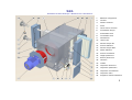
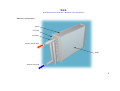
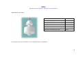
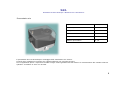
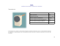
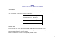
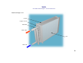
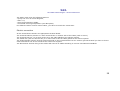
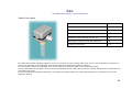
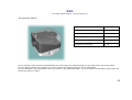
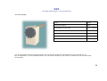
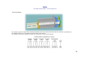
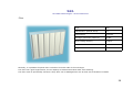
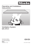
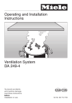
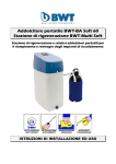
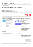
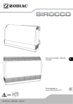
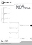
1 MAH0501 R.G.R. Scambiatori di calore Aria-Acqua – Manuale di uso e manutenzione 1. Batteria refrigerante 2. Girante 3. Motore elettrico 4. Filtro 5. Interruttore di livello 6. Flussostato acqua 7. Pressostato aria 8. Termostato aria 9. Morsettiera 10. Uscita cavi 11. Attacco acqua IN 12. Scarico batteria 13. Attacco acqua OUT 14. Sfiato batteria 15. Scarico condensa 16. Tappo posteriore 17. Blocco posteriore 18. Cassone 19. Golfari 20. Coperchio anteriore 21. Coperchio posteriore 22. Coperchio morsettiera 23. Coperchio filtro 24. Supporto elettroventilatore 2 R.G.R. Scambiatori di calore Aria-Acqua – Manuale di uso e manutenzione Batteria refrigerante Telaio Curvette Collettori Attacco acqua OUT Alette Attacco acqua IN 3 R.G.R. Scambiatori di calore Aria-Acqua – Manuale di uso e manutenzione Installazione Lo scambiatore va sollevato tramite gli appositi golfari in lamiera posti ai quattro angoli del cassone dello scambiatore. Evitare assolutamente di sollevare assieme allo scambiatore altri componenti, pena il distacco o la rottura dei golfari. Collegamento meccanico Lo scambiatore è provvisto di 4 o più fori per il fissaggio sul motore da refrigerare. In accordo con il cliente possono essere stati forniti dei raccordi. In tal caso vanno fissati prima questi ultimi sul motore e dopo va montato lo scambiatore. Lo scambiatore non è fonte di vibrazioni rilevanti, ma se queste fossero presenti sul motore, si rende necessario l’utilizzo di rosette elastiche (grower). In ogni caso va utilizzata viteria in acciaio (viti mat. 8.8 e dadi mat. 6S). Tra scambiatore e utilizzazione va interposta una adeguata guarnizione a cellule chiuse, che andrà rinnovata dopo ogni operazione di smontaggio per manutenzione o altro. Collegamento idraulico Lo scambiatore viene fornito con attacchi filettati (nippli) o con flangie avvitate. Il collegamento tra gli attacchi e l’impianto idraulico deve essere elastico, realizzato mediante un tubo flessibile lungo almeno mezzo metro. Il collegamento elastico evita i danni alla batteria refrigerante dovuti a: deformazioni o forzature per il collegamento, urti subiti dai tubi dell’impianto idraulico, vibrazioni dell’impianto idraulico, correnti galvaniche. La batteria è adatta al funzionamento con una pressione max di 5 bar. Evitare pertanto la formazione di pressioni istantanee elevate (colpo d’ariete) dovute a repentine chiusure o aperture del flusso d’acqua. La batteria va riempita lentamente avendo cura di evitare sacche d’aria in qualche ramo del refrigerante e installando (se non già presente) uno sfiato d’aria sul circuito idraulico. 4 R.G.R. Scambiatori di calore Aria-Acqua – Manuale di uso e manutenzione L’acqua deve avere le seguenti caratteristiche: • durezza non superiore ai 15 gradi francesi, • PH da 6 a 8, • esente da corpi estranei, • temperatura di ingresso controllata (vedi targa). In caso di valori diversi consultare sempre il costruttore. Collegamento elettrico Tutti i terminali sono cablati in una apposita morsettiera. La morsettiera può trovarsi in una cassetta morsettiera o in un vano sul fianco dello scambiatore. La cassetta morsettiera è dotata di 1 o 2 difese in lamiera per il fissaggio dei pressacavi. Il vano morsettiera è dotato di 2 o più fori per il fissaggio dei pressacavi. Per la messa a terra, oltre al morsetto di terra sulla morsettiera, utilizzare anche una delle viti della flangia dell’elettroventilatore. Per il dimensionamento ed il fissaggio di conduttori vanno seguite le normative vigenti. 5 R.G.R. Scambiatori di calore Aria-Acqua – Manuale di uso e manutenzione Interruttore di livello Tipo ILSP.S.2 Grado di protezione IP68 Temperatura di funzionamento -25 ÷ +100°C Tensione di commutazione max 220Vca Corrente di commutazione max 1A Potenza di commutazione max 60VA L’interruttore di livello è già tarato e non necessita di alcuna regolazione. 6 R.G.R. Scambiatori di calore Aria-Acqua – Manuale di uso e manutenzione Flussostato acqua Tipo FF81 Grado di protezione IP54 Temperatura del fluido -20 ÷ +110°C Tensione nominale di isolamento Ui 380Vca Corrente nominale di servizio continuativo Ith 7A Corrente nominale di impiego a 380Vca Ie 2A Attacco idraulico G1 Il flussostato acqua segnala la presenza o meno del flusso d’acqua, ma non è in grado di verificarne la corretta portata. La taratura va effettuata con l’impianto idraulico in funzione. Prima di ogni regolazione verificare che l’apparecchiatura non sia sotto tensione. Per la regolazione aprire il coperchio superiore ed agire sulla vite (rossa) che regola il contrasto del microswitch con la paletta. In presenza di forte turbolenza idraulica il flussostato va smontato e riposizionato su un tratto rettilineo dell’impianto. 7 R.G.R. Scambiatori di calore Aria-Acqua – Manuale di uso e manutenzione Pressostato aria Tipo DG6B / DG10B Grado di protezione IP54 Temperatura del fluido -15 ÷ +70°C Tensione di funzionamento 30 ÷ 240V Portata max dei contatti 5A Attacco pneumatico G 1/4 Il pressostato aria va tarato dopo il montaggio dello scambiatore sul motore. Prima di ogni regolazione verificare che l’apparecchiatura non sia sotto tensione. Per la regolazione aprire il coperchio frontale ed agire rotella graduata fino ad ottenere la commutazione del contatto elettrico quando il ventilatore si avvia o si arresta. 8 R.G.R. Scambiatori di calore Aria-Acqua – Manuale di uso e manutenzione Termostato aria Tipo CO3A Grado di protezione IP40 Temperatura del fluido +10 ÷ +90°C Tensione nominale di isolamento Ui 380Vca Corrente nominale di servizio continuativo Ith 15A Corrente nominale di impiego a 380Vca Ie 1.5A Attacco idraulico G 1/2 Il termostato aria va tarato in funzione della temperatura massima ammessa per l’aria in uscita dall’elettroventilatore. La regolazione si effettua agendo sulla rotella graduata frontale sulla quale è indicata la temperatura di intervento del termostato. 9 R.G.R. Scambiatori di calore Aria-Acqua – Manuale di uso e manutenzione Morsettiera La quantità e la numerazione dei morsetti può variare in funzione dei controlli collegati e dalle richieste del cliente. Lo schema sottostante rappresenta una morsettiera standard ed è assolutamente indicativo. Lo schema effettivo di collegamento viene inserito nella scatola o nel vano morsettiera dello scambiatore. 10 R.G.R. Scambiatori di calore Aria-Acqua – Manuale di uso e manutenzione Filtro Tipo A40 Classificazione (EN779:2002) G4 Composizione Poliestere Arrestanza gravimetrica media 90.8% Capacità accumulo polveri 575g/m2 Comportamento alla fiamma F1 – DIN 53438 Rigenerabilità Sì Il filtro a pannello può generalmente essere estratto da entrambi i lati dello scambiatore. Il materiale filtrante è rigenerabile ma la sua efficacia filtrante decade dopo alcuni lavaggi. Lo stato del filtro va verificato periodicamente. Un filtro troppo sporco potrebbe danneggiarsi e diventare inutilizzabile. 11 R.G.R. Scambiatori di calore Aria-Acqua – Manuale di uso e manutenzione Avvertenze per il corretto funzionamento Durante il funzionamento a regime verificare il salto termico dell’acqua. Se questo fosse inferiore a quanto indicato in targa, sarà possibile ridurre la portata d’acqua. Per questa operazione NON vanno assolutamente utilizzate le valvole a sfera eventualmente i dotazione con lo scambiatore. Se la temperatura di ingresso acqua è inferiore a 20°C è possibile la formazione interna di condensa. La temperatura va pertanto innalzata mediante preriscaldo o miscelazione con l’acqua in uscita. Quando viene fermato l’impianto utilizzatore non è consigliabile far circolare l’acqua nella batteria ancora a lungo perché potrebbe favorire il formarsi di condensa. È consentito invece continuare a far funzionare l’elettroventilatore. In caso di scarsa resistenza offerta all’elettroventilatore da parte dell’installazione collegata, è possibile che il motore trifase assorba più corrente di quanto indicato in targa. In questo caso va creata una caduta di pressione sul circuito aria mediante una strozzatura adeguata della bocca lato opposto ventilatore. Sullo scambiatore sono generalmente presenti a cavallo del filtro, 2 manicotti filettati (muffe) per l’applicazione di altri accessori o per la misurazione della pressione differenziale per il controllo dell’intasamento filtro. 12 R.G.R. Scambiatori di calore Aria-Acqua – Manuale di uso e manutenzione Manutenzione Gli intervalli di manutenzione variano a seconda dell’ambiente di installazione e della qualità dei fluidi in circolazione all’interno dello scambiatore. Nell’elenco sottostante sono indicati alcuni intervalli tipici consigliati. L’installatore provvederà, a seconda di casi e dei risultati delle prime ispezioni, a restringerne o ad ampliarne l’intervallo. Controllo filtro Ogni 15 giorni Pulizia alette batteria Ogni 6 mesi Controllo guarnizioni Ogni 30 giorni Controllo condensa Ogni 30 giorni Controllo ventilatore Ogni anno Pulizia generale Ogni 2 anni Controllo filtro Per l’estrazione del filtro aprire il coperchio filtro svitando i dadi relativi sul lato opposto alle cerniere. Estrarre il filtro utilizzando i forellini presenti sul telaio. Qualora il filtro fosse sporco è possibile rigenerarlo mediante lavaggio con acqua o detersivi non aggressivi e con relativa asciugatura con aria compressa in controcorrente. Dopo alcuni lavaggi va sostituito il materiale filtrante. Il telaio filtro è apribile per permettere la sostituzione del materiale filtrante. Prima di rimontare il filtro e chiudere il relativo coperchio, verificare lo stato delle guarnizioni e al caso sostituirle. 13 R.G.R. Scambiatori di calore Aria-Acqua – Manuale di uso e manutenzione Batteria refrigerante Per l’estrazione della batteria refrigerante è necessario eseguire questa sequenza di operazioni: • chiudere l’impianto idraulico, • verificare che lo scambiatore sia staccato dall’alimentazione elettrica generale, • vuotare la batteria refrigerante, • aprire il coperchietto del flussostato acqua e staccare i cavi ad esso collegati, • rimuovere la guaina ed il relativo raccordo dal flussostato acqua, • svitare i gruppi di attacco idraulico di ingresso e uscita acqua, • togliere il coperchio anteriore, • togliere il coperchio posteriore, • allentare o rimuovere i blocchi posteriori della batteria, • svitare i dadi che bloccano la batteria sul cassone (in qualche modello è necessario rimuovere anche l’interruttore di livello), • estrarre la batteria refrigerante. Durante questa ultima fase agire sempre sul telaio della batteria facendo attenzione a non danneggiare, spingendo o tirando, i collettori e le curvette in rame. Per la pulizia della batteria è sufficiente un soffio di aria compressa tra le alette insieme ad una spazzolatura mediante una spazzola a setole non metalliche. Per la pulizia interna dei tubetti, far scorrere acqua pulita con prodotti sgrassanti o decalcificanti, a seconda della qualità dell’acqua refrigerante. Si raccomanda di non utilizzare in nessun caso Idrazina o prodotti aggressivi per il rame. Per il montaggio della batteria, eseguire le stesse operazioni in senso inverso, sempre prestando la massima attenzione ai tubetti di rame, ai collettori e alle curvette. Prima di rimontare i coperchi verificare lo stato delle guarnizioni e, se rovinate o usurate, sostituirle. 14 R.G.R. Scambiatori di calore Aria-Acqua – Manuale di uso e manutenzione Controllo guarnizioni Le guarnizioni non devono presentare intagli o abrasioni e devono mantenere la loro elasticità. La compressione della guarnizione deve essere circa il 25% dello spessore della guarnizione stessa. Le guarnizioni, col tempo, perdono elasticità e rimangono efficienti solo se non vengono staccate dalle superfici di appoggio. Pertanto dopo ogni operazione di manutenzione verificare il grado di elasticità e, se necessario, sostituire le guarnizioni. Per gli scambiatori standard il tipo di guarnizione è N-SBR o NBR mousse a cellule chiuse. È consentito l’utilizzo di EPDM (Dutral). Controllo condensa Lo scambiatore è dotato di un interruttore di livello in grado di segnalare un accumulo pericoloso di condensa. In ogni caso è buona norma controllare periodicamente la quantità di condensa aprendo il rubinetto di scarico condensa posto sul coperchio anteriore. Vi è la possibilità che, con scambiatore in funzione, pur essendo presente un accumulo di condensa, questa non fuoriesca dal rubinetto. Ciò si verifica a causa della depressione interna creata dall’elettroventilatore. In questo caso si può scaricare la condensa svitando il relativo tappo presente sul coperchio posteriore o il rubinetto di scarico condensa. Controllo elettroventilatore La flangia ventilatore supporta il motore trifase sul quale è direttamente calettata la girante. Smontando la flangia si riesce a sfilare tutto il gruppo elettroventilatore. La pulizia della girante va effettuata mediante aria compressa e una spazzola a setole non metalliche. Si raccomanda di non rimuovere o spostare eventuali graffette o contrappesi di bilanciamento della girante. Se la girante presentasse qualche pala danneggiata o non rigidamente fissata sostituire immediatamente la girante. Pulizia generale Per effettuarla vanno smontati tutti i componenti dal cassone scambiatore. Vanno rimossi tutti i depositi di materiale estraneo che potrebbero influire sul buon funzionamento dello scambiatore. Va inoltre verificato lo stato delle saldature interne di diaframmi, convogliatori o altro che potrebbero aver risentito di eventuali vibrazioni. 15 R.G.R. Scambiatori di calore Aria-Acqua – Manuale di uso e manutenzione Problemi Problema Probabile causa Scarso scambio termico. L’aria non viene refrigerata Portata acqua troppo bassa. Aria nella batteria refigerante. Tubetti batteria sporchi. Circolazione batteria invertita. Sbagliato il senso di rotazione girante. Scarso flusso d’aria Strozzatura nel circuito d’aria. Filtro sporco. Sbagliato il senso di rotazione girante. Presenza di acqua nello scambiatore Perdita della batteria refrigerante. Condensa dovuta a bassa temperatura acqua. Condensa dovuta a fermo impianto. Riscaldamento del motore trifase Sbagliato il senso di rotazione girante. Alimentazione elettrica sbagliata. Eccessivo assorbimento di corrente. Vibrazioni Girante sporca. Girante sbilanciata o danneggiata. Rumorosità Eccessiva portata d’aria. Cuscinetti motore trifase difettosi. Strisciamento della ventola sul boccaglio. 16 R.G.R. Air to Water heatexchangers – Use and maintenance 1. Heatexhanger unit 2. Wheel 3. Electric motor 4. Filter 5. Water leak detector 6. Water flow switch 7. Air pressure switch 8. Air thermostat 9. Terminal Board 10. Cable holes 11. Water Inlet 12. Water discharge plug 13. Water Outlet 14. Air discharge plug 15. Drain valve 16. Rear plug 17. Rear lock 18. Frame 19. Hooks or eyebolts 20. Front cover 21. Rear cover 22. Terminal box cover 23. Filter cover 24. Electric fan support 17 R.G.R. Air to Water heatexchangers – Use and maintenance Heatexchanger unit Frame Copper curves Manifolds Water OUT Fins Water IN 18 R.G.R. Air to Water heatexchangers – Use and maintenance Installation The heatexchanger be lifted by means of the appropriate eyebolts or hooks, that are situated at the four corners of the frame. Do not lift with the exchanger other components. It is very dangerous because you can break or detach the eyebolts. Mechanical connection The heatexchanger as 4 or more holes thet are needful for the fixing on the motor that will be cooled. Yet, it is possible that some clients might have been supplied with some unions. In that case those unions should be fixed on the motor before the mounting of the heatexchanger. The heatexchanger doesn’t cause any considerable vibrations. Anyway, you can avoid further vibrations on the motor by means of a fixing with spring washer (grower). However you must always use steel bolts (screws mat. 8.8 – nuts mat. 6S). Between heatexchanger and motor must be interposed a suitable gasket, that will be renewed after any removal of the heatexchanger, due to maintenance or other operations. Hydraulic connection The heatexchanger is supplied with threaded connections (nippels) or screwed flanges. The necessary elasticity of the connection between the connections and the hydraulic system is possible thanks to an at least 0.5m flexible hose. That kind of linking can avoid serious damages to the cooling unit due to: • deformations or forced connection, • shocks and hits of the tubes in the hydraulic system, • vibrations of the hydraulic system, • gavanic currents. The heatexchanger unit can work at the highest pressure of 5 bar, avoiding istantaneous high pressure (water hammer) caused by sudden turning off or on of the water flow. The unit must be filled slowly (if present, open the air discharge plug), first of all avoiding the creation of air pockets in some pipe of the unit, and then installing an air bleed on the hydraulic circuit. 19 R.G.R. Air to Water heatexchangers – Use and maintenance The water must have the following features: • purity not over 15 French Degrees, • PH 6 ÷ 8, • free from extraneous solids, • controlled entering temperature (see data plate). For different values or other kind of water, you have to consult the constructor. Electric connection All the terminals are wired in an appropriate terminal board. The terminal board is present in a steel terminal box or inside a side of the frame (with its cover). The terminal box has 1 or 2 steel covers to fix the cable glands to the electric system. The frame has (near the electric fan) 2 or more holes to fix the cable glands to the electric system. The heatexchanger has an internal ground terminal on the terminal board. For an exterior ground terminal you have to fix the cable terminal to one of the screws of the electric fan support. The dimensions and the fixing of the cables will have to be made according to current international standards. 20 R.G.R. Air to Water heatexchangers – Use and maintenance Water leak detector Type ILSP.S.2 Protection degree IP68 Operating temperature -25 ÷ +100°C Max switching voltage 220Vca Max switching current 1A Max switching power 60VA The water leak detector is already calibrated and there is no need of any other adjustment. 21 R.G.R. Air to Water heatexchangers – Use and maintenance Water flow switch Type FF81 Protection degree IP54 Temperature of the fluid -20 ÷ +110°C Nominal insulation tension Ui 380Vca Continuous duty nominal current Ith 7A Operating nominal current with 380Vca Ie 2A Hydraulic connection G1 The water flow switch indicates whatever there is or if there isn’t the cooling water flow, but it is not to be able to measure or record the right flow. The calibration must be done when the hydraulic system is working. For your safety, before any operation turn off or remove the electric supply to the water flow switch. For the calibration lift the upper cover ad turn the calibration screw (red), which sets the contrast between the microswitch and the blade in the pipe. If there should be an hydraulic turbolence, the water flow switch had to be removed and placed in a rectilinear zone of the hydraulic system. 22 R.G.R. Air to Water heatexchangers – Use and maintenance Air pressure switch Type DG6B / DG10B Protection degree IP54 Temperature of the fluid -15 ÷ +70°C Switching voltage 30 ÷ 240V Switching capacity 5A Pneumatic connection G 1/4 The air pressure witch must be calibrated after the mounting of the heatexchanger on the motor which has to be cooled. For your safety, before any operation turn off or remove the electric supply to the air flow switch. For the calibration, open the plastic front cover and turn the graduated collar. You must find the commutation point when the electric fan starts or stops. 23 R.G.R. Air to Water heatexchangers – Use and maintenance Air thermostat Type CO3A Protection degree IP40 Temperature of the fluid +10 ÷ +90°C Nominal insulation tension Ui 380Vca Continuous duty nominal current Ith 15A Operating nominal current with 380Vca Ie 1.5A Hydraulic connection G 1/2 The air thermostat needs setting according to the maximum temperature admitted of the fan’s coming out air. For the calibration, turn the graduated collar. You can choose directly by the collar the temperature of the thermostat commutation. 24 R.G.R. Air to Water heatexchangers – Use and maintenance Terminal board The quantity and the initials of the terminals depends from the connected devices and the customer’s specifications. The diagram below it’s our standard terminal board (only sample). The effective connection diagram is inside the terminal box of the heatexchanger. 25 R.G.R. Air to Water heatexchangers – Use and maintenance Filter Type A40 Classification (EN779:2002) G4 Composition Polyester Average gravimetric efficiency 90.8% Dust holding capacity 575g/m2 Flame resistance F1 – DIN 53438 Regeneration Yes Normally, it is possible the panel filter extraction from each side of the exchanger. The filter has a good regeneration, but its capacity of filtration decreases after each washing. The filter must be periodically checked. A dirty filter can be damaged from the air flow and it becames unusable. 26 R.G.R. Air to Water heatexchangers – Use and maintenance Note During the working check the ∆t (difference between in – out temperature) of the water. If it should be lower than the values indicated on the data plate you could decrease the water flow. For this kind of operation you must NOT use the ball valve possibly supplied with the heatexchanger. The inlet water temperature could be below 20°C, creating internal condensate. In that case it is necessary to increase the temperature by preheating or mixing with the hot outlet water ((by a four-way valve or other). When the main motor (or plant) is stopped don’t get the water to flow in the battery, it could form some condensate. It is not necessary to stop the electric fan. If the connected main motor gives a scant pressure drop to the blower, the blower motor might absorb more quantity of current than that indicated on its data plate. In this case it must be created a pressure drop in the air circuit, limiting the area of the air opening on the opposite side of the fan (hot air opening). In the our standard construction there are on the heat exchanger, near the filter cover, 2 pipe couplings that need to install other devices or to measure the differential pressure in the exchanger. 27 R.G.R. Air to Water heatexchangers – Use and maintenance Maintenance The intervals of maintenance vary according to the installation enviroment ant the type of the fluids flowing inside the heatexchanger. The scheme below shows some advised intervals. The customer or the installer will enlarge or shorten the intervals, depending on the specific case or after the first check. Filter checking Every 15 days Exchanger unit fins cleaning Every 6 months Gaskets checking Every 30 days Water leak checking Every 30 days Fan wheel checking Every 1 year Global cleaning Every 2 years Filter cheking The filter can be removed by unscrewing the nuts situated on the filter cover and opening the cover. Then it can be taken out from the cooler frame by the two holes placed on the filter frame. In case the filter is dirty, it can be regenerated, washing it with water or soft detergents and then using a compressing air drying procedure. The filtering tissue has to be changed after some washing. You can open a corner of the filter frame for the tissue removing and changing. Before assembling the filter again, inspect the condition of the gasket and, if necessary, change them. 28 R.G.R. Air to Water heatexchangers – Use and maintenance Heatexchanger unit Remove the heatexchanger unit in the manner of followings: • close the hydraulic flow, • off the electric supply, • empty the unit, • open the cover of water flow switch and unplug the connected cables, • remove the cable gland from the water flow switch, • unscrew and remove the hydraulic connection groups (water inlet and water outlet), • remove the front cover, • remove the rear cover, • remove the rear locks, • loosen all the screw that fix the unit (in some models it is necessary to remove the water leak detector too), • take the unit out from the side of connections. Be very careful not to damage, by pushing or pulling, the manifolds, the collectors and the copper curves. You must pull or push only on the frame of the heatexchanger unit. Compressed air to the fins and a brushing with not metallic bristles brush are sufficient in order to clean the unit. As for the cleaning of the tubes, make clean water flow mixing it with degreasing and anti-calcium products, according to the quality of the cooling water. Never use Hydrazine or products that can be aggessive or harmful to copper. Reverse the above procedures to assemble the unit, ever being particulary careful with the copper curves and manifolds. Before mounting the covers, always inpect the conditions of the gaskets. 29 R.G.R. Air to Water heatexchangers – Use and maintenance Gasket checking The gaskets must not have any nicks or abrasions. The height of the compressed gasket must be 25% less than the height of the free gasket. The gaskets can become less elastic and can mantain the original efficiency only if they are not removed by their supporting surfaces. Therefore, after every maintenance, check the degree of elasticity and, if necessary, change the gaskets. The standard heatexchanger has closed cell rubber foam gaskets (N-SBR or NBR mousse). You can use an equivalent EPDM too. Condensation checking A leak level switch in the heatexchanger indicates when there is a dangerous accumulation of condensation. Anyway it is advisable to check the level of condensation periodically, opening the drain valve placed at the bottom of the front cover. While the heatexchanger is working it is also possible that, although there is too much condensation, it will not come out of the drain valve. That’s why the fan has been created to much depression inside the exchanger. So You hate to loosen the drain valve and/or the plug placed at the bottom of the rear cover. Electric fan checking The flange on the frame supports the three-phases motor and it supports the fan wheel. Taking the flange apart you manage to remove all the electric fan unit. The fan wheel has to be cleaned by using compressed air and a not metallic brush. Be careful not to move or remove possible clips for fan wheel balancy. If the fan wheel has any blade damaged it is necessary to change the fan wheel immediately. Global cleaning For a global cleaning take apart all the components of the heatexchanger. Remove all the extraneous materials that could cause bad working of the heatexchanger. Inspect also the conditions of the internal welding of brattices or conveyors or other parts that could have been damaged by eventual vibrations. 30 R.G.R. Air to Water heatexchangers – Use and maintenance Problem Probable causes Scant thermal efficiency. The air is not cooled Water flow too low. Air in the exchanger unit. Dirty exchanger unit tubes. Inverted water circulation. Inverted sense of rotation of the fan. Scant air flow Impediment in the air circuit. Dirty filter. Inverted sense of rotation of the fan. Water in the heatexchanger frame Water leak from a tube of the exchanger unit. Condensate due to low temperature of the water. Condensate due to plant stopped. Eletric fan motor is heating Inverted sense of rotation of the fan. Wrong electric supply. Working without pressure drop. Vibrations Dirty wheel. Damaged or unbalanced wheel. Excessive noise Working without pressure drop. Faulty bearing in the electric fan motor. The wheel is touching the cone. 31 R.G.R. Scambiatori di calore Aria-Acqua – Manuale di uso e manutenzione Air to Water heatexchanger – Use and maintenance Pagina Page 2 Scambiatore di calore Aria-Acqua 17 Air to Water heatexchanger 3 Batteria refrigerante 18 Heatexchanger unit 4 Installazione 19 Installation 4 Collegamento meccanico 19 Mechanical connection 4 Collegamento idraulico 19 Hydraulic connection 5 Collegamento elettrico 20 Electric connection 6 Interruttore di livello 21 Water leak detector 7 Flussostato acqua 22 Water flow switch 8 Pressostato aria 23 Air pressare switch 9 Termostato aria 24 Air thermostat 10 Morsettiera 25 Terminal board 11 Filtro 26 Filter 12 Avvertenze 27 Note 13 Manutenzione 28 Maintenance 13 Controllo filtro 28 Filter checking 14 Manutenzione batteria refrigerante 29 Heatexchanger unit checking 15 Controllo guarnizioni 30 Gasket checking 15 Controllo condensa 30 Condensation checking 15 Controllo elettroventilatore 30 Electric fan checking 15 Pulizia generale 30 Global cleaning 16 Problemi 31 Problems