1
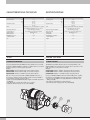
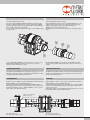
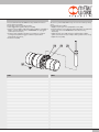
DZAK-2
USE AND MAINTENANCE
DZAK-2
USO E MANUTENZIONE
I
GB
CARATTERISTICHE TECNICHE
DATI TECNICI
Pressione d’esercizio
Temperatura d’esercizio
Fluido
Smorzamento di finecorsa
Controllo di finecorsa
Angolo di rotazione
Diametro del pistone
Ripetibilità (su 100 corse a
condizioni costanti)
Peso
DZAK-2
bar
MPa
psi
°C
°F
2÷7
0.2 ÷ 0.7
29 ÷ 101
-10 ÷ 80
14 ÷ 176
Aria filtrata 20 µm con o senza lubrificazione. Se si utilizza
aria lubrificata la lubrificazione deve essere continua.
Colonna d’aria agente come molla.
Sensori induttivi, sensori nella versione magnetica.
°
Regolabile da 0 ÷ 90
mm
32
≤ 0.05
°
kg
0.21
TECHNICAL DATA
Operating pressure
Temperature range
Fluid
End position stop shock-absorption
End-position control
Rotation angle
Piston diameter
Repeatability (on 100 strokes at
constant conditions)
Weight
USO
HOW TO USE
POSIZIONE DI MONTAGGIO
ASSEMBLY POSITION
DZAK-2
bar
MPa
psi
°C
°F
2 to 7
0.2 to 0.7
29 to101
-10 to 80
14 to 176
Lubricated or unlubricated 20 μm fi ltered air. If lubricated
air is used, lubrication must be continuous.
Air column acting as a spring.
Inductive sensors, sensors in the magnetic version
°
Adjustable from 0 to 90
mm
32
°
≤ 0.05
kg
0.21
L’accessorio Battuta intermedia DZAK-2 ha la possibilità di essere montato
di default sul DAPK-2/DAPIK-2 scegliendo in codifica l’opzione 3 posizioni
a destra, 3 posizioni a sinistra oppure 4 posizioni.
Esempio:
The DZAK-2 intermediate abutment can be mounted by default on the
DAPK-2/DAPIK-2 by specifying in the code the option “3 positions” to the
right, “3 positions” or “4 positions” to the left.
Example:
Nel caso si avesse invece acquistato un DAPK-2/DAPIK-2 privo di 3° e
4° posizione, sarebbe comunque possibile montare l’accessorio DZAK-2
successivamente seguendo questa procedura:
•Svitare il coperchio (100) dal tubo (80) e togliere il fondello comprensivo
di OR (90);
•Fare attenzione a non far entrare dello sporco nel tubo;
•Lubrificare l’interno del tubo con olio cod. 9910490;
If you buy a DAPK-2/DAPIK-2 without the 3rd and 4th position, it will be
possible to mount the DZAK-2 at a later stage by proceeding as follows:
•Unscrew the cap (100) from the pipe (80) and remove the base and
O-Ring seal (90);
•Be careful to prevent dirt from entering the pipe;
•Lubricate the inside of the pipe with oil code 9910490;
K202S303000K DAPK-2 + DZAK-2 (SX) con fermi elastici magnetico
K202D303000K DAPK-2 + DZAK-2 (DX) con fermi elastici magnetico
K2020403000K DAPK-2 + n°2 DZAK-2 con fermi elastici magnetico
2
SPECIFICATIONS
K202S303000K DAPK-2 + DZAK-2 (SX) magnetic with spring retainers
K202D303000K DAPK-2 + DZAK-2 (DX) magnetic with spring retainers
K2020403000K DAPK-2 + n°2 DZAK-2 magnetic with spring retainers
•Avvitare il DZAK-2 (110) sul tubo;
•Mount the DZAK-2 (110) on the pipe;
Una volta montato il DZAK-2 sul DAPK-2/DAPIK-2 è possibile regolare
la posizione angolare della sede sensore (130) e degli ingressi dell’aria
svitando leggermente la ghiera di bloccaggio (120) e ruotando il DZAK-2
fino a portarlo nella posizione desiderata.
A questo punto, avvitando la ghiera di bloccaggio, si fissa il DZAK-2 nella
nuova posizione.
Once the DZAK-2 has been mounted on the DAPK-2/DAPIK-2, you can
adjust the angle position of the sensor seat (130) and the air inlets by
slightly unscrewing the locking sleeve (120) and rotating the
DZAK-2 until it reaches the desired position.
The DZAK-2 is then secured in the new position by screwing the locking
sleeve.
Su un singolo DAPK-2/DAPIK-2 è possibile montare uno o due accessori
Battuta intermedia DZAK-2 ottenendo così una terza e una quarta
posizione di lavoro dell’attuatore rotante.
On each DAPK-2/DAPIK-2 you can mount two DZAK-2intermediate
abutments, thus providing a third and fourth work position of the rotary
actuator.
ALIMENTAZIONE D’ARIA
COMPRESSED AIR SUPPLY
La battuta intermedia DZAK-2 ha due filetti M5 di ingresso (come si vede
dal disegno seguente) che fungono da alimentazione dell’attuatore rotante
e da alimentazione della battuta intermedia stessa.
FUNZIONAMENTO
The DZAK-2 intermediate abutment comes with two M5 threaded inlet ports
(as shown in the diagram below), which supply air to the rotary actuator
and the intermediate abutment.
OPERATION
Quando l’accessorio DZAK-2 è montato, l’alimentazione dell’unità rotativa
DAPK-1/DAPIK-2 avviene tramite il filetto M5 (P1).
Per attivare la battuta intermedia basta alimentare il DZAK-2 tramite il
filetto M5 (P2); la terza posizione rimane attiva fino a che P2 ha pressione.
Togliendo l’alimentazione in P2, si disattiva il DZAK-2 e il ciclo successivo
verrà eseguito senza battuta intermedia.
With the DZAK-2 in place, compressed air is supplied to the rotary drive
DAPK-2/DAPIK-2 via the M5 threaded port (P1).
To activate the intermediate abutment, you only need to supply the DZAK-2
with air via the M5 threaded port (P2). The third position remains active
until P2 is pressurised.
Cutting off the supply to P2, the DZAK-2 is disabled and the next cycle will
be performed without an intermediate abutment.
Sede per sensore induttivo
Inductive sensor slot
P1 = Alimentazione aria
P2 = Alimentazione battuta intermedia
P1 = Compressed air supply
P2 = Intermediate abutment supply
3
REGOLAZIONE CORSA BATTUTA INTERMEDIA (3° e 4° posizione)
ADJUSTING THE INTERMEDIATE ABUTMENT STROKE (3rd and 4th position)
3 posizioni regolabili con 1 DZAK-2 / 3 adjustable positions with 1 DZAK-2
4 posizioni regolabili con 2 DZAK-2 / 4 adjustable positions with 2 DZAK-2
a = DAPK sinistra / left
b = DZAK destra / right
c = DAPK destra / right
a = DAPK sinistra / left
b = DZAK sinistra / left
c = DZAK destra / right
d = DAPK destra / right
φ = Angolo di rotazione DAPK: 0—180° in continuo / Angle of rotation DAPK: 0—180° continuous
ψ = Angolo di rotazione DZAK: 0—90° in continuo / Angle of rotation DZAK: 0—90° continuous
La regolazione della corsa della battuta intermedia DZAK-2 (3° e 4°
posizione) deve essere eseguita quando il rotante DAPK-2/DAPIK-2 è
montato in sede e con i DZAK-2 montati sul rotante.
La procedura di regolazione è la seguente:
•Alimentare il DZAK-2 da regolare con pressione 2 bar (ingresso aria
alimentazione battuta intermedia);
•Alimentare ingresso aria DAPK-2 opposto al DZAK-2 da regolare con
pressione 2 bar;
•Smontare il tappo (140) dal corpo del DZAK-2;
•Sbloccare senza svitare completamente le due viti M3x6 (150);
•Svitare (o avvitare) il piattello di bloccaggio ghiera (160) e la ghiera di
regolazione corsa (170) utilizzando l’apposita chiave fino a raggiungere
la posizione di regolazione desiderata;
•Serrare le due viti M2.5x5 sul piattello di bloccaggio ghiera;
•Chiudere il dispositivo riavvitando il tappo.
4
The stroke of the DZAK-2 intermediate abutment (3rd and 4th position) can
be adjusted when the DAPK-2/DAPIK-2 rotating shaft is mounted in place
and with the DZAK-2 abutments fitted to the rotating shaft.
The adjusting procedure is as follows:
•Supply air to the DZAK-2 to be adjusted at a pressure of 2 bar
(intermediate abutment air inlet);
•Supply air to the DAPK-2 opposite to the DZAK-2 to be adjusted at a
pressure of 2 bar;
•Remove the cap (140) from the body of the DZAK-2;
•Release without unscrewing the two M2.5x5 screws completely M2,5x5
(150);
•Unscrew (or screw) the plate of the locking sleeve (160) and the stroke
adjusting sleeve (170), using the wrench provided until the desired
position is reached;
•Tighten the two M2.5x5 screws on the locking sleeve plate;
•Screw in the cap to close the device.
MONTAGGIO SENSORE INDUTTIVO
L’accessorio Battuta intermedia DZAK-2 ha la possibilità di montare un
sensore di finecorsa induttivo.
Per il fissaggio seguire la seguente procedura:
•Svitare leggermente il grano (150) e la vite (140);
•Inserire il sensore induttivo (160) nella piastrina (130) fino a mandarlo in
battuta sul fondo della sede sensore. ATTENZIONE: solo appoggiare senza forzare verso il basso;
•Avvitare il grano (150) fino in battuta e poi avvitare per un ulteriore
1/4 di giro (un’avvitatura maggiore rischia di compromettere il
funzionamento del sensore);
•Avvitare la vite (140).
NOTE
HOW TO INSTALL THE INDUCTIVE SENSOR
The accessory intermediate DZAK-2 stop can mount an inductive proximity
sensor.
Proceed as follows to install it:
•Slightly loosen the grub screw (150) and the screw (140);
•Insert the inductive sensor (160) in the plate (140) until it rests against the
bottom of the sensor slot. IMPORTANT: insert it without forcing downwards;
•Tighten the grub screw (150) until it goes and then tighten a further
quarter of a turn (excess torque is likely to affect operation of the sensor);
•Tighten the screw (140).
NOTES
5
NOTE
6
www.metalwork.eu
NOTES
ZRCVK0004 - IM01_12/2014