1
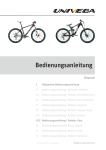
RAYSTAT-ECO-10
Energy-saving freeze protection
controller
Energiesparendes Steuergerät
für Frostschutzanwendungen
Régulateur économique pour
la mise hors gel
Unità di controllo antigelo
a risparmio energetico
Thermal BUILDING solutions
ML-RaychemRAYSTATECO10-IM-INST196
Rev9
English
Table of contents ..................................................................................... 2
Description & Technical data ................................................................... 6
Functional description ............................................................................. 7
Display ...................................................................................................... 7
Installation description ............................................................................ 8
Operational description ........................................................................... 11
Testing, commissioning and maintenance .............................................. 14
Wiring diagrams ...................................................................................... 42
Commissioning sheet .............................................................................. 45
Deutsch
Inhaltsverzeichnis ................................................................................... 2
Beschreibung und technische Daten ...................................................... 15
Funktionsbeschreibung ........................................................................... 16
Display ...................................................................................................... 17
Montage ................................................................................................... 18
Programmierung ..................................................................................... 20
Test, Inbetriebnahme und Wartung ......................................................... 23
Anschlussdiagramme .............................................................................. 42
Inbetriebnahmeprotokoll ......................................................................... 45
FRANçAIS
Table des matières .................................................................................. 2
Description & caractéristiques techniques ............................................. 24
Fonctionnement ....................................................................................... 25
Afficheur ................................................................................................... 26
Installation ............................................................................................... 27
Paramétrage ............................................................................................ 29
Test, mise en service et entretien ........................................................... 32
Schémas électriques ............................................................................... 42
Fiche de mise en service ......................................................................... 45
Italiano
Sommario ................................................................................................ 2
Descrizione e dati tecnici ......................................................................... 32
Descrizione funzionale ............................................................................ 33
Display ...................................................................................................... 33
Procedura di installazione ....................................................................... 34
Descrizione operativa .............................................................................. 38
Collaudo, messa in servizio e manutenzione .......................................... 41
Schemi elettrici ........................................................................................ 42
Scheda di messa in servizio ..................................................................... 45
2
A
1
9a
9b
V
DE
8
5
2
3
4
6
3
B
1.
4.
4
2.
5.
3.
6.
English
A1.Thermostat enclosure
2, 3, 4, 5. Cable entries
(2 x M25, 1 x M20, 1 x M16)
6.Temperature sensor Pt 100
7.Sensor cable
8.Push buttons
9.Digital display
DEutsch
A1.Thermostatgehäuse
2, 3, 4, 5. Einführungen
(2 x M25, 1 x M20, 1 x M16)
6.Temperatursensor Pt 100
7.Sensorkabel
8.Steuerungstasten
9.Digitales Display
français
A 1.Boîtier du thermostat
2, 3, 4, 5. Entrées de câbles
(2 x M25, 1 x M20, 1 x M16)
6.Sonde de température
Pt 100
7.Câble de la sonde
8.Touches de programmation
9.Afficheur numérique
Italiano
A1.Involucro del termostato
2, 3, 4, 5. Ingressi dei cavi
(2 x M25, 1 x M20, 1 x M16)
6.Sensore di temperatura
Pt 100
7.Cavo del sensore
8.Tasti
9.Display digitale
B1.Terminal screwdriver 3 mm
2.Posi-drive screwdriver
5 mm
3.Trimming knife
4, 5, 6. Spanners
(27 mm, 24 mm, 19 mm)
B1.Schraubendreher 3 mm,
Längsschlitz
2.Schraubendreher 5 mm,
Kreuzschlitz
3.Kabelmesser
4, 5, 6. Schraubenschlüssel
(27 mm, 24 mm, 19 mm)
B1.Tournevis 3 mm
2.Tournevis 5 mm
3.Cutter
4, 5, 6. Clés
(27 mm, 24 mm, 19 mm)
B1.Cacciavite per morsetti
3 mm
2.Cacciavite 5 mm
3.Taglierino
4, 5, 6. Chiavi
(27 mm, 24 mm, 19 mm)
5
Description
RAYSTAT-ECO-10 is an electronic controller with display, advanced alarm
facilities and the capability of switching large currents.
The RAYSTAT-ECO-10 is designed to control heating cable systems.
Heating cable can be controlled either directly by the RAYSTAT-ECO-10 or
via a contactor.
Direct switching of heating cables is possible for heating loads up to 25 A.
For heating loads greater than 25 A indirect switching via a suitably rated
contactor controlled by a RAYSTAT-ECO-10 is necessary. Installation
and all wiring must be in accordance with applicable regulations. The
device must be installed in non hazardous areas only. Pentair Thermal
Management offers other controls for use in hazardous areas.
Technical data
Supply voltage:230 Vac. +10%/–10%, 50/60 Hz
(6V leakproof maintenance-free nonrechargeable battery incl. for programming
without power supply)
Main relay:
max. 25 A, 250 Vac. Resistive
Heater operation on sensor error:
programmable: ON or OFF
Set point T range:
0°C to + 30°C
Accuracy:
±0,5 K at 5°C
Operatingtemperature:–30°C (–20°C, VDE approved) to +40°C
ambient
User interface:4 x 7 segment digital display
4 push buttons
alarm relay, max. 2 A, 250 Vac.
(Potential free)
Power terminals: 3 x 0,75 mm² to 4 mm²
Alarm terminals:
(3 + ) x 0,75 mm² to 2,5 m²
Sensor terminals: (3 + ) x 0,75 mm² to 2,5 mm²
Heater terminals:
(2 + ) x 0,75 mm² to 4 mm²
Enclosure
Exposure Temperature: –40°C to +80°C
Ingress Protection:
IP 65
Entries:
2 x M25, 1 x M20, 1 x M16
Size: 120 x 160 x 90 mm
Weight:
approx. 800 gr.
Material:
polycarbonate
Mounting:on a wall or directly on the pipe using
support brackets, SB-100 / SB-101
6
T sensor
Type:
Sensor head: 3-wire Pt 100 according to IEC Class B
50 mm x Ø 6 mm
* An external Pt 100 sensor can be connected, the sensor cable can be
extended with a 3-core shielded cable of 20 Ω max. per conductor (e.g. up
to 150 m with a 3 x 1.5 mm² cable)
Functional description
The Raystat-ECO-10 Controller is used to control heat-tracing freeze
protection systems based on ambient temperature. The controller adjusts
the power of the heating cable by energizing the circuit for a percentage
of a complete cycle. This percentage is determined based on the
ambient temperature, the set point, and the minimum expected ambient
temperature. The full cycle time is influenced by pipe diameter.
For example, if the ambient temperature is halfway between the
minimum expected ambient temperature and the set point, the heating
cable will be energized for 5 minutes and be off for 5 minutes (for the
smallest pipe size selected). The actual duty-cycle periods and ratios
vary, depending on the ambient temperature and the above mentioned
parameters. This algorithm is called Proportional Ambient Sensing
Control (PASC).
If you are unsure about the min. expected ambient setting, set it to a
higher rather than a lower value to prevent freeze-ups.
In the event of an error, the alarm relay switches and an error code shows
on the display. It is possible to program the status of the heating cable
(ON or OFF) in case of a sensor error.
The unit is fitted with a battery so that programming can be done on
the bench prior to mounting in the working location (see Operational
description, page 11).
Display
RAYSTAT-ECO-10 has a digital display. The three left hand digits 9a are
the value display and the right hand digit 9b is the status display.
7
There are 4 different display modes possible:
1.In the normal operation mode (no error condition), the measured
temperature or the set point temperature value are displayed in the
value display (alternating).
During the time that the actual measured temperatures is shown,
the TA LED in the status display lights up. At the moment that the set
point temperature is shown, the WT LED in the status display lights up.
Also during normal operation, the middle horizontal LED in the status
display lights up when the PASC algorithm is active.For example:
means –5°C measured temperature and PASC is active;
means set point temperature 5°C and PASC is active.
2.In case an error is detected, the value display shows “
” (flashing)
and the status display indicates the error number (see Errors).
3.Programming is done by means of the push buttons (see Operational
description). In the programming mode, the status display will indicate
the code of the parameter that is selected. The value display indicates
the value for the parameter.
4.When power is initially applied, all display segments will illuminate for
a short period. This will also occur if no mains power is available and
the battery button is pressed. Do not push the battery button when the
unit is powered, as this will shorten battery life.
Installation description
1. Installation of heating cable
For design and selection of heating cables in sanitary applications, follow
the Technical Handbook.
For selection of industrial heating cables, follow the Selection Guide for
Industrial Trace-Heating Systems or use the latest version of TraceCalc
or contact Pentair Thermal Management.
Follow the design guidelines and install the system in accordance with
the system specifications.
Follow the “Product Safety Notice” supplied with the heating cable.
Residual current device (RCD 30 mA) is required.
The RAYSTAT-ECO-10 is a sensitive electronic device, and should be
installed taking care of common guidelines for EMC interference.
8
2. Mounting of the enclosure
The RAYSTAT-ECO-10 can be installed indoor or outdoor.
Do not install the thermostat under the thermal insulation.
A.Wall mounting
Mount the enclosure using wall fasteners (screws) via the four, 4
mm Ø holes.
B.Mounting on a pipe
Pentair Thermal Management offers different support brackets
(not included) to mount the RAYSTAT-ECO-10 on a pipe: SB-100 or
SB-101.
3. Wiring
Remove the terminal protection cover to access the terminals.
Power cable
Enter a single phase (230 Vac.) power cable through the M25 gland 2
(see drawing A ) and wire according to the wiring diagram (page 33).
Wiring the heating cable can be done either:
A.Via junction box or contactor or when using RayClic with the cold
cable through the M25 gland 3 .
B.Directly into RAYSTAT-ECO-10.
In this case, the M25 gland 3 , which is delivered pre-mounted to
the RAYSTAT-ECO-10, is to be replaced by an appropriate kit.
Follow instructions supplied with the kit for installation.
Important: For Voltage Free Operation, the wire links (W1) and (W2) need
to be removed. Failure to remove the wire links can result in damage to
the unit or to other connected equipment. Wiring of RAYSTAT-ECO-10 to
a remote alarm is optional through the M20 gland 4 . Pentair Thermal
Management strongly recommends the use of a remote alarm for critical
operations (e.g. when extreme low temperatures (lower than –25°C) can
be expected or for critical processes).
9
4. Installation of the sensor
Location of the sensor
Mount the sensor in a position exposed to normal weather conditions but
shielded from direct sunlight. The sensor should not be located against
surfaces that are heated from within or may be heated by sunlight. If the
RAYSTAT-ECO-10 is located outdoors, the sensor cable may be shatened
and the sensor may be mounted directly to the bottom of the housing,
but make sure that at least 35 - 40 mm of the sensor extends beyond the
gland fitting and that the sensor is not in contact with other cables.
Warning: Do not install sensor at ambient temperatures below –20°C. Do
not bend sensor, keep it straight under all circumstances.
Wiring sensor to RAYSTAT-ECO-10
Enter the sensor cable through the indicated M16 gland 5 and wire as
shown in the wiring diagram (page 33). Please pay attention to color
coding of the wiring.
Remark: The sensor cable can be extended up to 150 m when a cross
section of 3 x 1.5 mm² is used (max. 20 Ω per conductor).
The connection between sensor cable and sensor extension can be made
in junction box JB-86 or equivalent. Use a shielded cable for extension to
avoid interference. The shielding braid is to be earthed in the thermostat.
5. Complete installation
Put the terminal protection cover back in place.
If RAYSTAT-ECO-10 is not yet programmed, please do so as described in
Operational description (page 11) and onwards.
Close the lid of the unit.
10
Operational description
1. Introduction
The RAYSTAT-ECO-10 parameters are configured via a menu system.
The unit is delivered with a battery so that the operating parameters can
be set up without any need for the power supply to be connected. This is
useful for setting units on the bench prior to mounting in their working
location or on site when power isn’t available.
) must not be pressed whilst
Please note that the Battery key (
the unit has the power supply connected. It will cause the battery to
discharge immediately. The battery will be disconnected automatically
when the last para-meter has been set.
Once programmed, the settings will be retained even in case of power
loss.
2. Activating and navigating the Menu in Set-Up mode
In order to activate the Set-up mode when the unit is not connected to a
) for about 2 sec.
mains power supply, press the Battery key (
This action will immediately light up all segments of the display, so
correct functioning of the display can be verified. The display will then
shortly show
, and switch to the first parameter to be changed.
In order to activate the Set-up mode when the unit is connected to a
mains power supply (the display alternates between the setpoint and
actual measured temperature), press the MENU key for about 2 sec. The
display will shortly show
, and switch to the first parameter to be
changed.
Stepping through the complete parameter list can be done by
successively pressing the MENU key. When the last parameter has
been set, the display will show
, and return to normal operation.
In case the unit is not connected to a power supply, the battery will be
disconnected.
If the unit is in Set-up mode, but no keys are activated, it will return to the
normal operation (or switch the battery off when the battery is used) after
about 30 sec.
To alter any parameter shown in the display, press the + or – keys. This
will allow the parameter to be raised or lowered to the maximum or the
minimum in integer steps.
If you require to reset all parameters to their default value, press the +
and – keys together for about 2 sec. If this is succesful, the display will
show
.
11
3. Parameters
The first parameter to show up during Set-up mode is the Set Point.
Other parameters, their default, minimum and maximum values are
shown in the below table:
Parameter
Set Point (°C)
Default
value
Displayed
Code
Min.
Max.
3
0
30
-20
-30
0
Pipe Size2
1
1
3
Heater Operation if Sensor Error
1
0 (OFF) 1 (ON)
Voltage Free Operation
0
0 (NO)
Min. Expected Ambient1 (°C)
1 Min.
1 (YES)
Expected Ambient Temp. is the temperature whereby the heating
cable is energized for 100%.
Min. Expected Ambient Temp. can only be set in steps of 10 K.
Min. Expected Ambient = Low Temp. Alarm.
2 Select Pipe Size Diameter:
3 for pipes ≥ 2 inch.
2 for pipes ≥ 1 inch.
1 for pipes < 1 inch.
12
4. Errors
RAYSTAT-ECO-10 can differentiate between 5 errors. The error is
displayed as soon as the error condition is detected. The alarm relay
switches at the same moment. The value display indicates “ ” (flashing)
and the status display indicates the error number.
1
2
Error Code
Description
Remedy
Short Circuit Sensor
(or very low resistance)
Replace sensor
Open Circuit Sensor
Connect sensor cable
or replace sensor
Temperature below
Min. Expected Ambient
Verify appropriateness
of setting
Output Voltage Error1
Relay or triac
malfunction/replace
unit
Supply below 207 Vac.2
Verify supply voltage
Detection of this error is disabled in Voltage Free Mode.
Unit is not active when supply voltage is below approx. 190 Vac.
All alarms are on the same alarm relay.
An alarm will clear automatically as soon as the error condition is gone.
There is no need to reset; all settings are maintained.
If multiple alarms are active, the alarms are shown with the following
priority:
(Highest),
,
,
,
(Lowest)
Note:
is not applicable to RAYSTAT-ECO-10.
13
Testing, commissioning and maintenance
Test heating cable when thermostat installation is complete as
directed in the instructions applicable for the heating cable. Fill out the
commisioning sheet (page 3514).
Maintain thermostat during normal plant maintenance.
Check:
• Mounting is firm
• Exposed sensor cable is not damaged
• Glands are tightened firmly
• Thermostat operation is correct (no error code displayed)
• Thermostat settings suits application
• Lid is closed firmly. Cladding is sealed with sealant.
Disposal of Waste batteries
(Applicable regulations for the European Union)
The crossed out dustbin on the product and/or packaging indicates that
the battery contained in the product shall not be disposable as part of
normal household waste.
The batteries must be disposed of responsibly to avoid potentially
negative consequences to the environment and/or human health.
The recycling of the materials can also help conserve natural resources.
For more information on battery disposal, please contact your local civic
office or your domestic waste disposal service.
14
Beschreibung
Das elektronische Steuergerät RAYSTAT-ECO-10 ist mit einem
digitalen Display und umfassenden Alarmfunktionen ausgestattet. Es
wurde speziell für die Begleitheizsysteme entwickelt und ist für hohe
Belastungen ausgelegt.
Das Heizband kann entweder direkt über das Steuergerät oder einen
Leistungsschütz geschaltet werden. Bei einem Schaltstrom von max. 25
A ist eine Schaltung über den Thermostaten zu empfehlen. Sollen mehr
als 25 A geschaltet werden, 50 ist ein Leistungsschütz zu verwenden.
Die Installation und der Anschluss des Steuergerätes müssen
entsprechend den örtlich geltenden Bestimmungen erfolgen.
Das Steuergerät RAYSTAT-ECO-10 darf nicht in explosionsgefährdeten
Bereichen installiert werden. Für explosionsgefährdete Bereiche bietet
Pentair Thermal Management spezielle Steuergeräte an.
Technische Daten
Betriebsspannung:AC 230V, +10%/–10%, 50/60 Hz
(inkl. einem auslaufgeschützten, wartungs-
freien, nicht-wiederaufladbaren 6 V-Akku)
Nennstrom: max. 25 A bei AC 230 V, ohmsche Last
Begleitheizung bei Programmierbar: EIN oder AUS
Sensorfehler:
Temperaturbereich:
0°C bis +30°C
Schaltpunktgenauigkeit: ±0,5 K bei 5°C
Umgebungstemperatur –30°C (–20°C, VDE zertifiziert) bis +40°C
bereich:
Benutzerschnittstelle:Digitales Display
4 Tasten zur Programmierung
Alarmrelais, Wechsler potentialfrei,
max. 2 A, AC 230 V
Stromanschluss:
3 Anschlussklemmen für 0,75 bis 4 mm2
Alarmrelais-Anschluss:3 Anschlussklemmen (+ ) für 0,75 mm2
bis 2,5 mm2
Sensorkabel-Anschluss:3 Anschlussklemmen (+ ) für 0,75 mm2
bis 2,5 mm2
Steuerrelais-Anschluss:2 Anschlussklemmen (+ ) für 0,75 mm2
bis 4 mm2
15
Gehäuse
Umgebungstemperatur-
bereich:
–40°C bis +80°C
Schutzart:
IP65
Bohrungen:
2 x M25, 1 x M20, 1 x M16
Abmessungen:
120 x 160 x 90 mm
Gewicht:
ca. 800 g
Material:
Graues Polycarbonat
Deckelbefestigung:4 x M6, Zylinderkpfschrauben - rostfreier
Stahl
Montage:Wandmontage oder auf Befestigungswinkel
SB-100/SB-101
Temperatursensor
Typ:
Sensor:
in 3-leitertechnik Pt 100 (IEC Class B)
50 mm x Ø 6 mm
* Es kann ein externer Pt 100-Sensor angeschlossen werden. Das
Sensorkabel kann mit einem 3-adrigen abgeschirmten Kabel, max. 20
W je Leiter, verlängert werden (bis zu 150 m bei einem Leiterquerschnitt
von 3 x 1,5 mm²)
Funktionsbeschreibung
Das Steuergerät RAYSTAT-ECO-10 wird zur Steuerung, unter Erfassung
der Umgebungstemperatur, von selbstregelnden Frostschutzsystemen
eingesetzt. Das Steuergerät passt die Ausgangsleistung des Heizbandes
durch eine prozentuale Energieversorgung des Heizkreises in Bezug
auf eine Zykluszeit an. Der Prozentsatz wird durch die gemessene
Umgebungstemperatur, die Haltetemperatur und die minimal zu
erwartende Umgebungstemperatur bestimmt. Die volle Zykluszeit wird
festgelegt durch den Rohrdurchmesser.
Beispiel: Liegt die gemessene Umgebungstemperatur genau
zwischen der minimal zu erwartenden Umgebungstemperatur und
der eingestellten Haltetemperatur, so wird das Heizband für 5 min
eingeschaltet und für 5 min abgeschaltet ( bei 1 Zoll Rohrnennweite).
Periodendauer und -verhältnis hängen von den zuvor erwähnten
Parametern ab. Diese Art der Steuerung wird umgebungstemperaturproportionale Steuerung bezeichnet.
Wenn Sie nicht sicher sind, welchen Wert Sie bei der minimalen
Umgebungstemperatur eingeben sollen, so wählen Sie einen etwas
höheren Wert um Frostschäden zu vermeiden.
16
Bei einer Störung schaltet das Alarmrelais, und in der Anzeige
erscheint eine Fehlermeldung. Sie können außerdem eingeben, ob das
Begleitheizsystem bei einem Sensorausfall abschalten oder weiter in
Betrieb bleiben soll (EIN oder AUS).
Das Steuergerät ist zusätzlich mit einer Batterie (im Lieferumfang)
ausgestattet, so dass die Programmierung auch ohne
Netzspannungsanschluss vorgenommen werden kann (siehe
„Programmierung“ auf Seite 20).
Display
Das Steuergerät RAYSTAT-ECO-10 ist mit einem digitalen Display
ausgestattet. Das dreistellige Display links 9a gibt die Messwerte an, die
Anzeige rechts 9b den Status.
Die Anzeige rechts gibt an, in welchen Betriebszustand sich die
Begleitheizung befindet:
1.Bei normalem Betrieb werden die aktuelle Umgebungstemperatur
oder der Sollwert für die Haltetemperatur links im Display
abwechselnd angezeigt.. Solange die aktuelle Umgebungstemperatur
angezeigt wird, leuchtet die LED TA in der Statusanzeige rechts. Wenn
die Haltetemperatur im linken Display angezeigt wird, leuchtet die LED
WT in der Statusanzeige. Im Normalbetrieb leuchtet auch die LED in
der Mitte. Sie zeigt an, dass der PASC-Algorithmus aktiviert ist.
Beispiel:
bedeutet, es werden aktuell –5°C gemessen, und
der PASC-Algorithmus ist aktiv.
bedeutet, die Haltetemperatur
beträgt 5°C, und der PASC-Algorithmus ist aktiviert.
2.Im Falle einer Störung blinkt in der linken Anzeige die Meldung „
“, und in der Statusanzeige erscheint ein Fehlercode (siehe
„Fehlermeldungen“).
3.Die Programmierung erfolgt mit Hilfe der Bedientasten (siehe
„Funktionsbeschreibung“). Während der Programmierung erscheint
in der Statusanzeige der Code für den Parameter, der gerade
programmiert wird. Im linken Display wird gleichzeitig der jeweilige
Wert angezeigt.
4.Wird die Spannungsversorgung eingeschaltet, so leuchten alle
Segmente im Display kurzzeitig auf. Dies geschieht auch, wenn
keine Spannungsversorgung angeschlossen ist und die BatterieTaste gedrückt wird. Drücken Sie die Batterie-Taste niemals, wenn
eine Spannungsversorgung angeschlossen ist, da sich sonst die
Lebensdauer der Batterie verkürzt.
17
Montage
1. Heizbandmontage
Informationen zur Auswahl und Auslegung von Frostschutzsystemen in
der Bautechnik finden Sie in unserem Technischen Handbuch.
Eine detaillierte Auswahlhilfe für industrielle Begleitheizsysteme
von Pentair Thermal Management finden Sie in unserer
Projektierungsanleitung für industrielle Begleitheizsysteme, bzw. in
unserer speziell entwickelten Planungssoftware „TraceCalc“. Für Fragen
zu Ihrer individuellen Anwendung wenden Sie sich bitte direkt an Ihre
Pentair Thermal Management-Vertretung.
Um die ordnungsgemäße Funktion des Systems sicherzustellen, müssen
die Auslegungsvorschriften und die Montageanleitung exakt befolgt
werden. Beachten Sie bitte auch das mitgelieferte Sicherheitsdatenblatt.
Hinweis: Es ist ein Fehlerstromschutzschalter (30mA) erforderlich.
Der RAYSTAT-ECO-10 ist ein empfindliches elektronisches Gerät
und sollte unter Berücksichtigung der allgemeinen Richtlinien zur
elektromagnetischen Verträglichkeit (EMV) installiert werden.
2. Gehäusemontage
Das Steuergerät RAYSTAT-ECO-10 kann im Freien oder innerhalb von
Gebäuden montiert werden. Montieren Sie das Gerät nicht unter der
Wärmedämmung!
A.Wandmontage
Für die Wandmontage sind vier Löcher für M4-Schrauben im
Gehäuse.
B.Montage auf der Rohrleitung
Pentair Thermal Management bietet auch Befestigungswinkel (nicht
im Lieferumfang enthalten) für die Montage des Steuergerätes auf
der Rohrleitung an: SB-100 oder SB-101.
3. Anschluss
Entfernen Sie zuerst die Gehäuseabdeckung.
Anschlusskabel
Führen Sie ein 3-adriges Anschlußkabel (AC 230V) durch die dafür
vorgesehene M25-Verschraubung 2 (siehe Zeichnung A ) und schließen
Sie das Kabel entsprechend dem Anschlußdiagramm auf Seite 33 an.
18
Heizbandanschluss
A.Das Heizband kann über einen Anschlußkasten, ein Leistungsschütz
oder RayClic mit dem Kaltende des Anschlußmoduls direkt durch
die M25-Verschraubung 3 angeschlossen werden.
B.Das Heizband kann auch direkt im Steuergerät angeschlossen
werden. In diesem Fall muss die M25-Verschraubung 3 , die bei
der Lieferung bereits am Steuergerät montiert ist, durch eine
entsprechende Anschlussgarnitur ersetzt werden (siehe Tabelle
S. 20). Montieren Sie die Anschlussgarnitur entsprechend der
mitgelieferten Montageanleitung.
Hinweis: Für potentialfreien Betrieb müssen die Verbindungskabel (W1
und W2) entfernt werden, da sonst das Steuergerät oder andere, daran
angeschlossene Komponenten beschädigt werden können. Über die
M20-Verschraubung (4) kann das Steuergerät RAYSTAT-ECO-10 auch
an eine externe Alarmeinheit angeschlossen werden. Für Anwendungen
mit speziellen Anforderungen empfiehlt Pentair Thermal Management
den Einsatz einer externen Alarmeinheit (z.B. bei extrem niedrigen
Umgebungstemperaturen (unter –25°C) oder kritischen Prozessen).
4. Sensormontage
Montageort des Sensors
Montieren Sie den Sensor an einer Stelle, wo er normalen
Wetterbedingungen, jedoch nicht direkter Sonneneinstrahlung
ausgesetzt ist. Der Sensor sollte ebenfalls nicht auf Oberflächen
montiert werden, die indirekt von der Sonne erwärmt werden. Wenn
das Steuergerät RAYSTAT-ECO-10 im Freien montiert wird, kann das
Sensorkabel gekürzt und der Sensor direkt am Gehäuseboden montiert
werden. In diesem Fall sollten Sie jedoch sicherstellen, dass der Sensor
mindestens 35–40 mm über die Verschraubung hinausragt und nicht in
Kontakt mit anderen Kabel kommt.
Warnung: Montieren Sie den Sensor nicht bei Umgebungstemperaturen
unter –20°C. Verbiegen Sie den Sensor auf keinen Fall.
Anschluss des Sensors an das Steuergerät
Führen Sie das Sensorkabel durch die dafür vorgesehene M16Verschraubung 5 und schließen Sie es entsprechend dem
Anschlussdiagramm auf Seite 37 an. Bitte beachten Sie die
Farbcodierung der einzelnen Adern!
Hinweis: Das Sensorkabel kann mit einem 3-adrigen abgeschirmten
Kabel, max. 20 Ω je Leiter, verlängert werden (bis zu 150 m bei
einem Leiterquerschnitt von 3 x 1,5 mm2). Die Verbindung zwischen
Sensorkabel und Verlängerungskabel kann in einem Anschlusskasten
vom Typ JB-86 (oder gleichwertig) erfolgen. Verwenden Sie ein
geschirmtes Kabel, um Interferenzen zu vermeiden. Das Schutzgeflecht
muss im Thermostat geerdet werden.
19
5. Fertigstellung der Montage
Bringen Sie die Gehäuseabdeckung wieder an. Wenn Sie das Steuergerät
RAYSTAT-ECO-10 noch nicht programmiert haben, folgen Sie nun den
Hinweisen im Kapitel „Programmierung“ auf Seite 20. Schließen Sie den
Deckel des Gehäuses.
Funktionsbeschreibung
1. Einleitung
Die RAYSTAT-ECO-10 Parameter sind über ein System-Menü einstellbar.
Das Steuergerät ist zusätzlich mit einer Batterie ausgestattet, so dass die
Programmierung auch ohne Netzspannungsanschluss erfolgen kann.
) nur gedrückt werden
Bitte beachten Sie, dass die Batterie-Taste (
darf, wenn das Steuergerät nicht unter Spannung steht, da sich die
Batterie ansonsten sofort entlädt. Der Batteriebetrieb wird nach Eingabe
des letzten Parameters automatisch beendet.
Die Programmierung bleibt auch nach einem Spannungsausfall erhalten.
2. Programmierung
Um den Programmiermodus ohne Spannungsversorgung zu aktivieren,
drücken sie die Batterie-Taste für ca. 2 Sekunden. Alle Segmente im
Display leuchten sofort kurzzeitig auf. Auf diese Weise können Sie
feststellen, ob das Display fehlerfrei funktioniert. Im Display erscheint
kurz
und anschließend der erste einstellbare Parameter.
Um den Programmiermodus bei Netzbetrieb zu aktivieren (im Display
erscheint abwechselnd Haltetemperatur oder aktuelle gemessene
Temperatur), drücken Sie die Menü-Taste für ca. 2 Sekunden. Im
Display erscheint kurz
und anschließend der erste einstellbare
Parameter.
Die einstellbaren Parameter können schrittweise durch drücken
der Menü-Taste aufgerufen werden. Nach Eingabe des letzten
Parameters erscheint
im Display und das Gerät arbeitet wieder im
Normalbetrieb.
Im Fall, daß das Steuergerät nicht an die Netzspannung angeschlossen
ist, wird der Batteriebetrieb beendet.
Befindet sich das Gerät im Programmiermodus und es werden keine
Tasten betätigt, so schaltet das Steuergerät nach 30 Sekunden in den
Normalbetrieb zurück (bei Batteriebetrieb wird diese abgeschaltet).
Die im Display erscheinenden Parameter lassen sich schrittweise mit
den Taste + und – verändern.
20
Wenn das Steuergerät auf seine Werkseinstellungen zurückgesetzt
werden soll, dann drücken Sie gleichzeitig die Tasten + und – für ca. 2
Sekunden.
Im Display erscheint anschließend
(Default).
3. Parameter
Der erste angezeigte Parameter im Display während des
Programmiermodus ist die Haltetemperatur. Andere Parameter,
Werkseinstellungen, Minimum- und Maximumwerte können aus der
folgenden Tabelle entnommen werden.
Parameter
Haltetemperatur (°C)
Min. Umgebungstemperatur1
(°C)
Werkseitige
Einstellung
Code
Min.
Max.
3
0
30
-20
-30
0
1
3
Rohrnennweite2
1
Abschalten bei Sensorausfall
1
0 (AUS) 1 (EIN)
Potentialfreier Betrieb
0
0 (NEIN)
1 (JA)
1
enn die minimale Umgebungstemperatur erreicht ist, schaltet das
W
Begleitheizsystem auf Dauerbetrieb.
Die minimale Umgebungstemperatur kann nur in 10 K-Schritten
angepasst werden.
Min. Umgebungstemperatur = Untertemperaturalarm
2 Geben Sie die Rohrnennweite ein:
3 für Rohre ≥ 2 Zoll
2 für Rohre ≥ 1 Zoll
1 für Rohre < 1 Zoll
4. Fehler
Das Steuergerät RAYSTAT-ECO-10 kann fünf verschiedene Arten von
Störungen unterscheiden. Wenn eine Störung vorliegt, erscheint eine
entsprechende Meldung im Display. Gleichzeitig schaltet das Alarmrelais.
Im linken Display erscheint die Meldung „
“ (blinkend), und in der
Statusanzeige wird der entsprechende Fehlercode angezeigt.
21
1
2
Fehlercode
Beschreibung
Abhilfe
Sensorkurzschluss
(oder sehr geringer
Widerstand)
Sensor ersetzen
Sensorverbindung
unterbrochen
Sensorkabel
anschliessen oder
Sensor ersetzen
Gemessene
Temperatur
liegt unter min.
Umgebungstemperatur
Messwert überprüfen
Relaiskontakt schließt1
nicht mehr
Relais defekt/Einheit
ersetzen
Versorgungsspannung
unter AC 207V2
Spannung überprüfen
Bei potentialfreiem Betrieb wird diese Störung nicht gemeldet.
Das Steuergerät schaltet ab, wenn die Versorgungsspannung unter
AC 190V fällt.
Alle Alarme werden über das selbe Relais weitergemeldet.
Der Alarm wird automatisch zurückgesetzt, sobald der Fehler behoben
ist. Es ist nicht erforderlich, das Steuergerät neu zu programmieren; alle
Einstellungen bleiben erhalten.
Treten mehrere Fehler gleichzeitig auf, so werden diese in folgender
Priorität zur Anzeige gebracht:
(höchste),
,
,
,
(kleinste).
Hinweis: Fehlercode 4 ist bei diesem Steuergerät nicht belegt.
22
Test, Inbetriebnahme und Wartung
Nachdem Sie das Steuergerät montiert haben, prüfen Sie, ob das
Heizband ordnungsgemäß funktioniert. Hinweise zur Überprüfung
finden Sie in der Montageanleitung des Heizbandes. Nun füllen Sie das
Inbetriebnahmeprotokoll aus (Seite 35).
Das Steuergerät sollte in regelmäßigen Abständen gewartet werden.
Prüfen Sie, ob
• das Steuergerät fest montiert ist
• das Sensorkabel beschädigt wurde
• alle Verschraubungen fest angezogen sind
• das Steuergerät korrekt arbeitet (keine Fehlermeldung im Display)
• die Einstellungen den Anforderungen entsprechen
• der Gehäusedeckel fest verschlossen ist
• die Wärmedämmung abgedichtet ist.
Entsorgung alter Batterien
(geltende Bestimmunen für die Europäische Union)
Das Symbol der durchgestrichenen Mülltonne auf dem Produkt und/
oder seiner Verpackung weist darauf hin, dass die im Produkt enthaltene
Batterie nicht im normalen Haushaltsmüll entsorgt werden darf.
Die Batterien müssen verantwortungsbewusst entsorgt werden, um
negative Folgen für Gesundheit und Umwelt zu vermeiden.
Das Recycling der Werkstoffe kann darüber hinaus zur Schonung
natürlicher Ressourcen beitragen.
Weitere Informationen zur Entsorgung von Batterien erhalten Sie von
Ihren Stadtwerken oder dem örtlichen Müllentsorgungsdienst.
23
Description
Le RAYSTAT-ECO-10 est un régulateur électronique avec un afficheur, des
fonctions d’alarme avancées et la capacité de commuter des courants
importants.
Il est conçu pour réguler les systèmes de traçage électrique.
Le ruban chauffant est commandé soit directement par le RAYSTATECO-10 soit par le biais d’un contacteur.
La mise sous tension directe du circuit est possible pour des charges
jusqu’à 25 A. Pour des puissances supérieures, il faut une commutation
indirecte par un contacteur de calibre suffisant commandé par le
RAYSTAT-ECO-10.
Installation et câblage doivent être conformes aux réglementations en
vigueur. Le régulateur est prévu pour une installation en zone ordinaire
uniquement. La gamme Pentair Thermal Management comprend
d’autres dispositifs de régulation pour les zones explosibles.
Caractéristiques techniques
Tension d’alimentation: 230 Vca +10%/–10%, 50/60 Hz
(pile 6 V étanche non rechargeable pour
programmation sans alimentation secteur)
Relais de commande:
25 A, 250 Vca, résistif
Mode sécurité pour défaut sonde: programmable: circuit ON ou OFF
Plage de réglage de température: 0°C à + 30°C
Précision: 0,5 K à 5°C
Température de
fonctionnnement:–30°C (–20°C, certifié VDE) à +40°C
ambiante
Interface utilisateur:afficheur numérique 4 x 7 segments
4 touches de commande
relais d’alarme, max. 2 A, 250 Vca
(sans potentiel)
Bornes d’alimentation: 3 x 0,75 mm2 - 4 mm2
Connexion relais d’alarme: (3 + ) x 0,75 mm2 - 2,5 mm2
Connexion sonde de température: (3 + ) x 0,75 mm2 - 2,5 mm2
Connexion circuit de traçage: (2 + ) x 0,75 mm2 - 4 mm2
24
Boîtier
Température de service:
Protection: Entrées:
Dimensions: Poids approx.: Matériau: Montage: –40°C à +80°C
IP 65
2 x M25, 1 x M20, 1 x M16
20 x 160 x 90 mm
800 g
polycarbonate
sur paroi ou support du fixation
sur la tuyauterie SB-100 / SB-101
Sonde de température
Type: Sonde Pt 100 à 3 fils selon classe B de
l’IEC
Tête: 50 mm x Ø 6 mm
Une sonde PT 100 externe peut être connectée. Son câble peut être
prolongé par un câble 3 conducteurs tressé de 20 Ω max. par conducteur
(par exemple 150 m max. avec un câble 3 x 1,5 mm2).
Fonctionnement
Le régulateur RAYSTAT-ECO-10 est utilisé dans les systèmes de
protection contre le gel qui s’appuient sur la température ambiante. Le
régulateur adapte la puissance du ruban chauffant en commandant sur
un cycle complet, un pourcentage de mise sous tension du circuit de
traçage.
Ce pourcentage est déterminé à partir de la température ambiante, du
point de consigne et de la température minimale ambiante prévue. La
durée d’un cycle complet est aussi fonction du diamètre de la tuyauterie.
Par exemple, si la température ambiante est à mi-chemin entre la valeur
minimale prévue et le point de consigne ( = 5°C par ex.), le ruban
chauffant sera activé puis désactivé pour des périodes de 5 minutes
chacune (pour la plus petite tuyauterie sélectionnée). La longueur réelle
des cycles et leur durée relative varient en fonction de la température
ambiante et des paramètres mentionnés ci-dessus; c’est la régulation
proportionnelle selon la température ambiante ou PASC.
La température ambiante minimale ( ) doit être réglée sur la base des
spécifications de l’étude. Ce n’est que lorsque ce seuil minimal est atteint
que le ruban chauffant est à 100 % sous tension.
25
En cas d’hésitation à propos du réglage adéquat, il vaut mieux choisir
une valeur trop élevée que trop basse pour éviter tout risque de gel des
conduites.
En cas d’erreur, le relais d’alarme est sollicité et un code d’erreur est
donné par l’afficheur. Il est possible de programmer l’état que prendra le
ruban chauffant en situation d’erreur (sous ou hors tension).
L’appareil est équipé d’une pile qui permet une programmation préalable
avant montage et raccordement sur place (voir Paramétrage, page 29).
Afficheur
Le RAYSTAT-ECO-10 est équipé d’un afficheur numérique. Les trois
chiffres de gauche 9a correspondent à la valeur mesurée et le chiffre de
droite 9b est un affichage d’état.
Quatre modes d’affichage sont possibles:
1.En fonctionnement normal (absence d’erreur), la température
mesurée et la température de consigne s’affichent alternativement
dans la partie gauche de l’afficheur. Lorsque la température mesurée
est affichée, la diode TA s’allume à droite, lorsque la consigne est
affichée, c’est la diode WT qui s’allume. La diode du milieu s’allume
également en fonctionnement normal lorsque l’algorithme PASC est
actif. Par exemple,
indique que la température mesurée est de
-5°C et que PASC est actif ;
indique que la valeur de consigne
programmée est de 5°C et que PASC est actif.
2.Lorsqu’une erreur est détectée, l’affichage de gauche clignote en
montrant “
” et l’affichage d’état donne un numéro permettant
d’identifier le problème (voir Erreurs).
3.Les touches servent à la programmation (voir Paramétrage). En mode
de programmation, l’affichage d’état indiquera le code du paramètre
sélectionné et la valeur de ce paramètre s’affichera à gauche.
4.Lors de la mise sous tension initiale, tous les éléments d’affichage
s’allument simultanément pendant une courte durée. Cela se produit
aussi lorsqu’il n’y a pas d’alimentation principale et que la touche Pile
est appuyée (ne pas appuyer sur la touche Pile lorsque l’appareil est
sous tension car cela réduit la durée de vie de la pile).
26
Installation
1. Pose du ruban chauffant
Pour l’étude et la sélection des rubans chauffants dans les applications
bâtiment, voir le Manuel Technique.
Pour les rubans chauffants destinés à l’industrie, voir le Guide de
sélection industrie, utiliser la dernière version du logiciel TraceCalc ou
encore prendre contact avec votre agent Pentair Thermal Management.
Respecter la marche à suivre et procéder à l’installation en conformité
avec les caractéristiques du système.
Suivre les recommandations de la fiche de sécurité fournie avec les
rubans. Disjoncteur différentiel (30 mA) est indispensable.
Le RAYSTAT-ECO-10 est un appareil électronique sensible. Il doit donc
être installé en prenant en compte les règles classiques de protection
aux interférences EMC.
2. Montage du boîtier
Le RAYSTAT-ECO-10 peut s’installer à l’intérieur comme à l’extérieur. Ne
pas installer le régulateur sous le calorifuge.
A.Montage mural
Fixer le boîtier au mur au moyen des vis insérées dans les quatre
trous de fixation de 4 mm.
B. Installation sur tuyauterie
Pentair Thermal Management propose différents supports (non
inclus dans la fourniture) pour monter le RAYSTAT-ECO-10 sur la
tuyauterie: SB-100 / SB-101 / SB-110.
27
3. Câblage
Ôter le capot du terminal pour accéder aux bornes de connexion.
Alimentation:
Faire passer un câble monophasé (230 Vca) dans le presse-étoupe 2 ,
taille M25 (schéma A ) et raccorder selon le schéma électrique de la
page 37.
Raccordement du ruban chauffant:
A.Via une boîte de jonction ou un contacteur, ou en utilisant RayClic,
avec le câble froid dans le presse-étoupe 3 (M25).
B.Directement sur le RAYSTAT-ECO-10.
Dans ce cas, le presse-étoupe 3 (livré prémonté sur l’appareil), doit
être remplacé par un kit approprié.
Suivre les instructions d’installations fournies avec le kit.
Important: En fonctionnement contact sec (contacteur), les cavaliers (W1)
et (W2) doivent impérativement être enlevés sous peine d’endommager
l’appareil ou un autre équipement connecté. Le raccordement du
RAYSTAT-ECO-10 à une alarme à distance est une option qui utilise le
presse-étoupe 4 (M20). Pentair Thermal Management recommande
vivement une alarme distante pour les applications critiques, lorsque des
températures basses extrêmes sont à envisager (inférieures à –25°C) ou
pour des procédés thermosensibles.
4. Installation de la sonde
Emplacement
Installer la sonde dans un endroit soumis à des conditions
météorologiques normales mais abrité du soleil. Elle ne doit pas se
trouver contre des surfaces réchauffées de l’intérieur ou par les rayons
du soleil. Si le RAYSTAT-ECO-10 est monté à l’extérieur, le câble de la
sonde peut être escamoté et la sonde montée directement sur la base
du boîtier mais il faut s’assurer qu’au moins 35–40 mm de la sonde sort
au-delà du presse-étoupe et que la sonde n’est pas en contact avec
d’autres câbles.
Attention: ne pas installer la sonde lorsque la température ambiante est
inférieure à –20°C. Ne pas plier la sonde, elle doit rester droite en toutes
circonstances.
Raccordement de la sonde au RAYSTAT-ECO-10
Faire passer le câble de la sonde dans le presse-étoupe 5 (M16) et
raccorder selon le schéma électrique de la page 33.
Les codes couleur du câblage doivent être respectés.
28
Remarque: le câble de la sonde peut être prolongé jusqu’à 150 m avec
un câble de section 3 x 1,5 mm2. Raccorder cette prolongation dans une
boîte de jonction JB-86 ou dispositif équivalent. Utiliser un câble blindé
pour éviter les interférences. La tresse de blindage doit être reliée à la
prise de terre du régulateur.
5. Fin de l’installation
Remettre le capot de protection du bloc de connexion en place.
Si ce n’est pas encore fait, programmer le RAYSTAT-ECO-10 en suivant
les instructions relatives au Paramétrage, voir ci-dessous.
Fermer le couvercle de l’appareil.
Paramétrage
1. Introduction
Les paramètres du RAYSTAT-ECO-10 se programment grâce à un
système de menu.
L’appareil est fourni avec une pile, ce qui permet de régler les
paramètres d’exploitation sans branchement à l’alimentation réseau. Les
thermostats peuvent ainsi être réglés en atelier avant leur installation
sur le lieu d’utilisation mais aussi sur site quand l’alimentation électrique
n’est pas disponible.
) pendant que
Attention: ne pas appuyer sur la touche de la pile (
l’appareil est raccordé à l’alimentation électrique. La pile se déchargerait
immédiatement. La pile sera automatiquement déconnectée après le
réglage du dernier paramètre.
Les réglages programmés sont conservés même en cas de panne de
courant secteur.
2. Mode paramétrage: Initialisation et navigation dans le
menu
Pour mettre le thermostat en mode de paramétrage lorsque l’appareil
n’est pas raccordé à l’alimentation électrique, appuyer sur la touche Pile
(
 ) pendant 2 secondes environ. Tous les segments de l’afficheur
s’allument brièvement pour permettre le contrôle du fonctionnement
de l’affichage. L’afficheur indique ensuite
et passe au premier
paramètre à définir.
29
Pour mettre le thermostat en mode de paramétrage lorsque l’appareil est
raccordé à l’alimentation électrique (l’afficheur indique alternativement
le point de consigne et la valeur de température mesurée), appuyer sur la
touche MENU pendant 2 secondes environ.
Parcourir la liste complète des paramètres effectués en appuyant
successivement sur la touche Menu. Quand le dernier paramètre est
reglé, l’afficheur indique
, et retourne au mode de fonctionnement
normal. Dans le cas où l’appareil n’est pas raccordé à l’alimentation
électrique, la pile sera déconnectée.
Si l’appareil est en mode de paramétrage, mais qu’aucune touche
n’est appuyée, il retourne en mode de fonctionnement normal (et
déconnecte la pile) après environ 30 secondes. Pour modifier n’importe
quel paramètre indiqué sur l’afficheur, appuyer sur les touches Plus
+ où Moins – . Cela permet d’augmenter ou de diminuer la valeur du
paramètre aux valeurs maximum ou minimum par nombres entiers.
Si vous désirez réinitialiser tous les paramètres à leur valeur par
défaut, appuyer simultanément sur les deux touches Plus + et Moins –
pendant environ 2 secondes. Si cela est positif, l’afficheur indique
.
3. Paramètres
Le premier paramètre indiqué pendant le mode paramétrage est le point
de consigne. Les autres paramètres, leurs valeurs par défaut, minimum
et maximum sont indiqués dans le tableau suivant.
Paramètre
Code
affiché
Min.
Max.
3
0
30
-20
-30
0
Diam. tuyauterie
1
1
3
Etat ruban si erreur de sonde
1
0 (OFF)
1 (ON)
Fonctionnement sans
alimentation
0
0 (NON) 1 (OUI)
Consigne (°C)
Temp. ambiente min. (K)
1
Valeur par
défaut
a temp. ambiante min. est la température à laquelle le ruban chauffant
L
est sous tension à 100 %.
Elle se règle en pas de 10 K.
La temp. ambiante min. équivaut à l’alarme temp. basse.
30
2
pécifier le diamètre de tuyauterie:
S
3 pour diam. ≥ 2 pouces
2 pour diam. ≥ 1 pouce
1 pour diam. < 1 pouce
4. Erreurs
Le RAYSTAT-ECO-10 est capable d’identifier 5 erreurs. Il affiche l’erreur
dès que le problème est détecté, en même temps que s’enclenche le
relais d’alarme. L’afficheur côté valeur indique en clignotant “
” et le
code d’erreur correspondant est indiqué à droite.
1
2
Code d’erreur
Description
Remède
Court-circuit sonde (ou
résistance très faible)
Remplacer la sonde
Circuit ouvert sonde
Raccorder câble sonde
ou remplacer sonde
Température inférieure
à ambiante min.
Vérifier adéquation du
réglage
Erreur tension de
sortie1
Défaillance du relais ou
triac/remplacer
Alimentation <
Contrôler la tension
d’alimentation
207 Vca2
Détection inopérante en mode contact sec (contacteur).
L’appareil cesse de fonctionner quand la tension est inférieure à 190 Vca
environ.
Toutes les alarmes sont sur le même relais.
L’alarme est automatiquement annulée avec la fin du signal d’erreur.
Il n’est pas nécessaire de réinitialiser, tous les réglages sont conservés.
Si plusieurs alarmes sont activées, les alarmes sont affichées dans
l’ordre
de priorité suivant:
(la plus haute),
,
,
,
(la plus basse).
Remarque: l’erreur 4 n’est pas applicable au RAYSTAT-ECO-10.
31
Test, mise en service et entretien
Procéder à l’essai du ruban chauffant à la fin de l’installation du
régulateur conformément aux instructions de Pentair Thermal
Management concernant le ruban chauffant. Compléter la fiche de mise
en service (page 35).
Vérifier et entretenir le régulateur lors de la maintenance régulière des
installations.
Contrôles:
• Solidité du montage.
• État du câble de la sonde.
• Presse-étoupe bien serrés.
• Fonctionnement correct du régulateur (pas de code d’erreur).
• Réglages du régulateur adaptés à l’application.
• Fermeture du couvercle.
• Calorifuge étanche.
Collecte et recyclage de piles usagées
(directives applicables dans l’Union européenne)
Le sigle de la poubelle barrée figurant sur le produit et/ou son emballage
indique que les piles contenues dans ce produit ne doivent pas être
déposées avec les autres ordures ménagères.
Les piles doivent être recyclées de manière responsable pour éviter toute
conséquence potentiellement négative pour l’environnement et/ou la
santé humaine.
Le recyclage des matériaux peut également favoriser la préservation des
ressources naturelles.
Pour plus d’informations sur la collecte et le recyclage des piles, veuillez
contacter le service concerné de votre municipalité ou le service national
de traitement des déchets.
32
Descrizione
RAYSTAT-ECO-10 è un controllore elettronico dotato di display, funzioni di
allarme avanzate e la capacità di commutare correnti elevate.
RAYSTAT-ECO-10 è progettato per controllare sistemi di tracciatura elettrica.
I cavi scaldanti possono essere controllati direttamente dall’unità RAYSTATECO-10 o attraverso un contattore.
La commutazione diretta dei cavi scaldanti è possibile con valori di carico
non superiori a 25 A. Per valori di carico superiori a 25 A è necessaria una
commutazione indiretta mediante un contattore opportunamente dimensionato,
controllato da un’unità RAYSTAT-ECO-10. L’installazione e i collegamenti
elettrici devono essere eseguiti in conformità alle norme applicabili. Il dispositivo
può essere installato solo in aree non pericolose. Pentair Thermal Management
offre altre unità di controllo idonee all’utilizzo in zone pericolose.
Dati tecnici
Tensione di alimentazione:230 Vca +10%/–10%, 50/60 Hz
(con batteria stagna non ricaricabile
da 6V, esente da manutenzione, per la
programmazione senza rete di alimentazione)
Relè principale:max. 25 A, 250 Vca, resistivo
Modalità di funzionamento
in caso di errore del sensore: programmabile: ON o OFF
Temperatura impostata
(setpoint): Da 0°C a + 30°C
Precisione:
±0,5 K a 5°C
Temperatura di esercizio:Temperatura ambiente da -30°C (-20°C,
omologazione VDE) a +40°C
Interfaccia utente:Display digitale a 4 x 7 segmenti
4 tasti
relè di allarme, max. 2 A, 250 Vca
(senza potenziale)
Connettori di potenza: 3 x 0,75 mm² - 4 mm²
Connettori di allarme:
(3 + ) x 0,75 mm² - 2,5 m²
Connettori dei sensori: (3 + ) x 0,75 mm² - 2,5 mm²
Connettori cavi scaldanti: (2 + ) x 0,75 mm² - 4 mm²
Involucro
Temperatura di esposizione: Da -40°C a +80°C
Classe di protezione IP:
IP 65
Ingressi:
2 x M25, 1 x M20, 1 x M16
Dimensioni: 120 x 160 x 90 mm
Peso:
ca. 800 g
Materiale:
policarbonato
Montaggio:a parete o direttamente sulla tubazione
mediante staffe di supporto, SB-100 / SB-101
33
Sensore di temperatura
Tipo:
Testa del sensore: Pt 100 a 3 fili, conforme alla norma IEC Classe B
50 mm x Ø 6 mm
* È possibile collegare un sensore Pt 100 esterno; il cavo del sensore può essere
prolungato con un cavo schermato a 3 conduttori da 20 Ω max. per conduttore
(es. fino a 150 m con un cavo da 3 x 1,5 mm²)
Descrizione funzionale
L’unità di controllo Raystat-ECO-10 permette di controllare i sistemi di
tracciamento elettrico con funzione antigelo sulla base della temperatura
ambiente. Il controllore regola la potenza del cavo scaldante alimentando il
circuito in modalità ciclica. Le fasi del ciclo vengono determinate in base alla
temperatura ambiente misurata, al setpoint e alla temperatura ambiente
minima prevista. La durata del ciclo completo dipende dal diametro della
tubazione.
Se ad esempio la temperatura ambiente corrisponde ad un valore intermedio
tra la temperatura minima prevista e il setpoint, il cavo scaldante sarà
alimentato per 5 minuti e quindi disattivato per 5 minuti (per la tubazione più
piccola selezionata). La durata e i rapporti dei cicli di funzionamento variano in
base alla temperatura ambiente e ai parametri sopra indicati. Questo algoritmo
è denominato PASC (Proportional Ambient Sensing Control).
Se non si è certi del valore minimo della temparatura prevista, è preferibile
approssimare il valore per eccesso piuttosto che per difetto per evitare rischi di
congelamento.
In caso di errore, il relè di allarme viene attivato e sul display compare un codice
di errore. È possibile programmare lo stato operativo del cavo scaldante (ON o
OFF) in caso di errore del sensore.
L’unità è dotata di una batteria interna, perciò la programmazione può essere
eseguita prima di procedere all’installazione nella posizione di lavoro (vedere
Descrizione operativa, pag. 11).
Display
RAYSTAT-ECO-10 dispone di un display digitale. Le tre cifre a sinistra 9a
indicano il valore misurato, mentre la cifra a destra 9b è un’indicazione di stato.
34
Il display può operare in quattro modalità:
1. In modalità di funzionamento normale (senza condizioni di errore), la parte
sinistra del display mostra a fasi alterne la temperatura misurata e il
setpoint.
Quando è visualizzata la temperatura misurata, nella parte destra del
display si accende il LED TA. Quando è visualizzata la temperatura impostata
(setpoint), nella parte destra del display si accende il LED WT. Sempre in
modalità di funzionamento normale, il LED orizzontale centrale nella parte
destra del display si accende quando è attivo l’algoritmo PASC. Ad esempio:
Indica che la temperatura misurata è di -5°C e che l’algoritmo PASC
è attivo;
indica che il setpoint è di 5°C e che l’algoritmo PASC è attivo.
2. In caso di errore, nella parte sinistra del display lampeggia l’indicazione
“
” e nella parte destra viene indicato il numero di identificazione
dell’errore (vedere Errori).
3. La programmazione deve essere effettuata mediante i tasti (vedere
Descrizione operativa). In modalità di programmazione, la parte destra del
display mostra il codice del parametro selezionato. A sinistra viene indicato il
valore di quel parametro.
4. Alla prima accensione, tutti i segmenti del display si accendono per pochi
istanti. Questo accade anche se l’alimentazione elettrica non è disponibile
e viene premuto il tasto della batteria. Non premere il tasto della batteria
quando l’unità è accesa, perché questo abbrevierebbe la vita utile delle
batterie.
Procedura di installazione
1. Installazione del cavo scaldante
Per la progettazione e la selezione dei cavi scaldanti da utilizzare in applicazioni
sanitarie, seguire le indicazioni del manuale tecnico.
Per la selezione dei cavi scaldanti da utilizzare in applicazioni industriali, seguire
la guida alla selezione dei sistemi di tracciamento elettrico industriali o usare
l’ultima versione di TraceCalc, oppure contattare Pentair Thermal Management.
Seguire le linee guida per la progettazione e installare il sistema attenendosi
alle specifiche riportate.
Seguire le “avvertenze di sicurezza del prodotto” allegate al cavo scaldante.
È obbligatorio l’uso di un interruttore differenziale (RCD 30 mA).
L’unità RAYSTAT-ECO-10 è un dispositivo elettronico, e dovrebbe
essere installata seguendo le linee guida generali per le interferenze
elettromagnetiche.
35
2. Montaggio dell’involucro
L’unità RAYSTAT-ECO-10 può essere installata in ambienti chiusi
o all’aperto.
Non installare il termostato sotto l’isolamento termico.
A.Montaggio a parete
Montare l’involucro mediante tasselli (a vite) usando i quattro fori
con Ø 4 mm.
B.Installazione su tubazioni
Pentair Thermal Management offre diverse staffe di supporto (non
incluse) per l’installazione dell’unità RAYSTAT-ECO-10 su una
tubazione: SB-100 o SB-101.
3. Cablaggio
Rimuovere la copertura di protezione dei terminali.
Cavo di alimentazione
Introdurre un cavo di alimentazione monofase (230 Vca) nel pressacavo
M25 2 (vedere il disegno A ) ed eseguire i collegamenti seguendo lo
schema elettrico (pag. 33).
Il collegamento del cavo scaldante può essere effettuato:
A.Mediante una cassetta di giunzione o un contattore; oppure, se si
utilizza un’unità RayClic, facendo passare il cavo freddo attraverso il
pressacavo M25 3 .
B.Direttamente nell’unità RAYSTAT-ECO-10.
In questo caso il pressacavo M25 3 , che viene consegnato
preinstallato nell’unità RAYSTAT-ECO-10, deve essere sostituito con
un kit appropriato.
Per l’installazione, seguire le istruzioni incluse nel kit.
Importante: per l’utilizzo del termostato con contatto libero da tensione,
è necessario rimuovere i ponticelli (W1) e (W2). La mancata rimozione dei
ponticelli può determinare un danno all’unità o ad altre apparecchiature
connesse. Il collegamento opzionale dell’unità RAYSTAT-ECO-10 a un
allarme remoto può essere effettuato attraverso il pressacavo M20 4 .
Pentair Thermal Management raccomanda l’utilizzo di un allarme remoto
per le applicazioni di natura critica (ad esempio, quando la temperatura
ambiente può raggiungere valori estremamente bassi (al di sotto di
-25°C) oppure per processi particolarmente critici).
36
4. Installazione del sensore
Posizione del sensore
Installare il sensore in una posizione esposta a condizioni atmosferiche
normali ma al riparo dalla luce diretta del sole. Il sensore non deve
essere collocato contro superfici che siano riscaldate dall’interno o che
possano essere riscaldate dalla luce solare. Se l’unità RAYSTAT-ECO-10
è installata all’esterno, il cavo del sensore può essere posizionato
all’interno della scatola e il sensore può essere montato direttamente sul
fondo dell’involucro; occorre tuttavia che almeno 35-40 mm del sensore
si estendano oltre il pressacavo e che il sensore non sia a contatto con
altri cavi.
Avvertenza: non installare il sensore a temperature ambiente inferiori
a -20°C. Il sensore deve restare diritto e non deve essere piegato in
nessuna circostanza.
Collegamento del sensore all’unità RAYSTAT-ECO-10
Inserire il cavo del sensore attraverso il pressacavo M16 5 ed eseguire
il collegamento come mostrato nello schema elettrico (pag. 33). Prestare
attenzione ai colori identificativi dei cavi.
Nota: Il cavo del sensore può essere prolungato fino a 150 m se si utilizza
una sezione di 3 x 1,5 mm² (max. 20 Ω per conduttore).
Il collegamento tra il cavo del sensore e la relativa estensione può essere
realizzato nella cassetta di giunzione JB-86 o in un’unità equivalente. Per
l’estensione, usare un cavo schermato per evitare interferenze. La calza
schermante deve essere collegata a terra nel termostato.
5. Completamento dell’installazione
Riapplicare la copertura di protezione dei terminali.
Se l’unità RAYSTAT-ECO-10 non è ancora stata programmata, procedere
come indicato nella descrizione operativa (pag. 11) e nelle sezioni
successive.
Chiudere il coperchio dell’unità.
37
Descrizione operativa
1. Introduzione
I parametri dell’unità RAYSTAT-ECO-10 devono essere configurati
attraverso un sistema a menu.
Il dispositivo è provvisto di una batteria interna, che consente di
configurare i parametri operativi senza bisogno di collegare l’unità
all’alimentazione elettrica. Questo è particolarmente utile per configurare
le unità prima del montaggio nella posizione di lavoro o in luoghi in cui
non è disponibile una fonte di alimentazione elettrica.
) quando l’unità è collegata
Nota: non premere il tasto della batteria (
alla rete elettrica. Così facendo si produrrebbe un rapido esaurimento
della batteria. La batteria si disconnette automaticamente una volta
terminata l’impostazione dell’ultimo parametro.
Le impostazioni, una volta programmate, saranno mantenute anche in
caso di interruzione della rete di alimentazione.
2. Attivazione della modalità di configurazione
Per attivare la modalità di configurazione quando l’unità non è collegata
) per circa
all’alimentazione elettrica, premere il tasto della batteria (
2 secondi.
Si accenderanno tutti i segmenti del display, consentendo di verificare
il suo corretto funzionamento. Sul display comparirà per pochi istanti
l’indicazione
, quindi verrà mostrato il primo parametro da
modificare.
Per attivare la modalità di configurazione quando l’unità è collegata
all’alimentazione elettrica (il display mostra in sequenza il setpoint e
la temperatura misurata), premere il tasto MENU per circa 2 secondi.
Sul display comparirà brevemente l’indicazione
, quindi verrà
mostrato il primo parametro da modificare.
Per scorrere l’elenco dei parametri, premere ripetutamente il tasto
MENU. Dopo l’impostazione dell’ultimo parametro, il display mostra
l’indicazione
e quindi torna alla modalità normale. Se l’unità non è
collegata alla rete elettrica, la batteria si disattiva automaticamente.
Se l’unità è in modalità di configurazione ma non viene premuto nessun
tasto, essa ritorna automaticamente alla modalità normale (o, in caso di
funzionamento a batteria, quest’ultima si disattiva) dopo circa 30 secondi.
Per modificare i parametri mostrati sul display, premere i tasti + o – .
I valori dei parametri potranno essere aumentati o diminuiti di un’unità
fino alle rispettive impostazioni massime e minime.
Se si desidera ripristinare tutti i parametri predefiniti, premere insieme
i tasti + e – per circa 2 secondi. Se l’operazione viene eseguita
correttamente, sul display compare l’indicazione
.
38
3. Parametri
Il primo parametro che compare quando si attiva la modalità di
configurazione è il setpoint. La tabella qui sotto mostra gli altri
parametri, i rispettivi valori predefiniti e le impostazioni minime e
massime consentite:
Parametro
Setpoint
Valore
Codice
predefinito visualizzato
Min.
Max.
3
0
30
-20
-30
0
Diametro tubazione2
1
1
3
Funzionamento del circuito
scaldante in caso di errore del
sensore
1
0
(OFF)
1 (ON)
Funzionamento con contatto libero
da tensione
0
0 (NO)
1 (SÌ)
Temp. ambiente min. prevista1 (°C)
1 La
temperatura ambiente minima prevista è la temperatura alla quale il
cavo scaldante viene alimentato per il 100% del ciclo di lavoro.
La temperatura ambiente minima prevista può essere impostata a
incrementi di 10 K.
La temperatura ambiente minima equivale all’allarme di bassa
temperatura.
2 Selezionare il diametro della tubazione:
3 per tubazioni ≥ 2 pollici
2 per tubazioni ≥ 1 pollice
1 per tubazioni < 1 pollice
39
4. Errori
L’unità RAYSTAT-ECO-10 riconosce cinque tipi di errore. L’errore
viene visualizzato non appena l’unità rileva la condizione anomala
corrispondente, e allo stesso tempo viene attivato il relè di allarme. Nella
parte sinistra del display lampeggia l’indicazione “ ” e nella parte destra
viene visualizzato il numero di errore.
Codice di errore
Descrizione
Rimedio
Sensore in
cortocircuito (o
resistenza molto
bassa)
Sostituire il sensore
Sensore con circuito
aperto
Collegare il cavo del
sensore o sostituire il
sensore
Temperatura inferiore
alla temperatura
ambiente minima
prevista
Verificare la correttezza
dell’impostazione
Anomalia tensione in
uscita1
Malfunzionamento
del relè o del triac/
sostituire l’unità
Alimentazione inferiore
a 207 Vca2
Verificare la tensione di
alimentazione
1
Nella modalità di funzionamento con contatto libero da tensione, il
rilevamento di questo errore è disabilitato.
L’unità non si attiva se la tensione di alimentazione è inferiore a circa
190 Vca.
2
Tutti gli allarmi vengono segnalati attraverso lo stesso relè.
Gli allarmi si disattivano automaticamente non appena le relative
condizioni di errore vengono risolte. Non è necessario eseguire un reset
dell’unità, e tutte le impostazioni vengono mantenute.
Se sono attivi più allarmi, essi vengono mostrati con la seguente priorità:
(massima),
,
,
,
(minima)
Nota:
40
non è applicabile all’unità RAYSTAT-ECO-10.
Collaudo, messa in servizio e manutenzione
Dopo l’installazione del termostato, collaudare il cavo scaldante come
descritto nelle istruzioni del prodotto. Compilare la scheda di messa in
servizio (pag. 3541).
Eseguire la manutenzione del termostato durante la normale
manutenzione dell’impianto.
Controllare:
• La solidità dell’installazione
• L’integrità del cavo del sensore
• Il serraggio dei pressacavo
• Il corretto funzionamento del termostato (nessun codice di
errore sul display)
• La corretta regolazione del termostato per il tipo di
applicazione
• La corretta chiusura del coperchio. La tenuta stagna del
rivestimento.
Smaltimento delle batterie usate
(norme applicabili per l’Unione Europea)
Il simbolo con la croce sul bidone riportato sul prodotto e/o
sull’imballaggio indica che la batteria contenuta nel prodotto non deve
essere smaltita insieme ai normali rifiuti domestici.
Le batterie devono essere smaltite responsabilmente per evitare possibili
conseguenze negative sull’ambiente e/o sulla salute umana.
Il riciclaggio dei materiali può inoltre contribuire alla conservazione delle
risorse naturali.
Per maggiori informazioni sullo smaltimento delle batterie, contattare le
autorità locali competenti o il servizio di smaltimento dei rifiuti operante
nella propria zona.
41
A. Wiring Diagrams
Anschlussdiagramm
Schémas électriques
Schemi elettrici
L1
N
Max.
C 25 A
30 mA
RAYSTAT-ECO-10
A B C
5 L L 8 N N
W/B
W1
R R
*
W2
alarm*
2A max.
R: Same colour
R: d
ie gleiche Farbe
R: l a même couleur
R: Stesso colore
Heating cable
Heizband
Ruban chauffant
Cavo scaldante
42
Temp. sensor Pt 100
Temp.Sensor Pt 100
Sonde de température
Sensore di temperatura Pt 100
* Optional
* Optional
* Option
* Opzionale
B. Voltage free operation: Remove links W1 and W2 and change “U” parameter in set up
mode from “0” (not volt free) to “1” (volt free) as explained on page 13 of this manual.
Potentialfreier Berieb: Entfermen Sie die Brücken W1 und W2 und ändern Sie
die den Parameter für potentialfreien Betrieb “U” von “0” (potentialbehaftet)
auf “1” (potentialfrei) wie auf Seite 23 in der Montage- und Bedienungsanleitung
beschrieben.
Fonctionnement hors potentiel : enlever les cavaliers W1 et W2 et changer dans
le mode de configuration le paramètre “U” : de la position “O” (sous potentiel) à la
position “1” (hors potentiel) (voir explications page 34 du manuel technique)
Funzionamento con contatto libero da tensione: Rimuovere i ponticelli W1 e W2,
quindi accedere alla modalità di configurazione e cambiare il parametro “U” da “0”
(con tensione) a “1” (senza tensione) come descritto a pag. 13 del manuale.
Heating cable
Heizband
Ruban chauffant
Cavo scaldante
External contactor
and power supply
Externes Leistungsschütz und
Spannungsversorgung
Alimentation et
contacteur externe
Contattore esterno
ed alimentazione
*** Optional
*** Optional
*** Option
*** Opzionale
Temp. Pt 100 sensor
Temp.Sensor Pt 100
Sonde de température
Sensore di temp. Pt 100
R: Same colour
R: die gleiche Farbe
R: la même couleur
R: Stesso colore
* Electrical protection by circuit-breaker may be needed for local circumstances, standards and regulations.
** Depending on the application, one- or three-pole circuit-breakers or contactors may be used.
* Örtliche Gegebenheiten, Normen und Vorschriften können zwei- bzw. vierpolige Abschaltung durch
Leitungsschutzschalter erforderlich machen.
** In Abhängigkeit von der Anwendung sind sowohl einals auch dreipolige Leitungsschutzschalter bzw.
Schütze möglich.
* Les conditions locales ainsi que la réglementation et la législation en vigueur peuvent rendre
nécessaire une protection électrique par disjoncteur.
** Selon le type d’application, on utilisera des disjoncteurs ou contacteurs monopolaires ou tripolaires.
* Condizioni specifiche di installazione, norme e regolamenti locali possono richiedere una protezione
elettrica mediante interruttore.
** A seconda dell’applicazione, possono essere utilizzati interruttori o contattori unipolari o tripolari.
43
CB / Sicherung / Disjoncteur / Interruttore:................... A Type: ............... RCD / FI-Schutzschalter / Disj. Différentiel / RCD: ������������������� mA
Heater / Heizband / Ruban / Cavo scaldante: .................... Length / Länge / Longueur / Lunghezza : �������������������������������������������������������������� m
Sensor / Sensor / Sonde / Sensore: ................................... Length / Länge / Longueur / Lunghezza: ��������������������������������������������������������������� m
Voltage (Free Operation) / Potentialfreier Betrieb /
Fonctionnement contact sec / Tensione (senza tensione):
Heater Operation if Sensor Error / Abschalten bei Sensorausfall /
État circuit si erreur de sonde / Modalità in caso di errore del sensore:
Pipe Size / Rohrnennweite / Diam. tuyauterie / Diam. tubazione:
Min. Exp. Ambient / Min. Umgebungstemp. / Temp. ambiante min. (K) / Temp. ambiente min.:
Set Point / Haltetemperatur / Consigne / Setpoint:
Setting / Einstellung / Réglage / Impostazione
Batch No. / Los Nr / Lot n° / Lotto n.: ......................... Display / Display / Afficheur / Indicazione
Date / Datum / Date / Data: �����������������������������������������������������������������
Parameter / Parameter / Paramètre / Parametro
Ref. / Ref. / Réf. / Rif.: ���������������������������������������������������������������������������
Location / Ort / Location / Luogo: �������������������������������������������������������
RAYSTAT-ECO-10
Commissioning / Inbetriebnahme / Mise en service / Messa in servizio
België / Belgique
Italia
РОССИЯ
Bulgaria
Lietuva/Latvija/Eesti
Serbia and Montenegro
Česká Republika
Tel. +420 241 009 215
Fax +420 241 009 219
[email protected]
Magyarország
Schweiz / Suisse
Danmark
Nederland
Suomi
Deutschland
Norge
Sverige
España
Tel. 34 902 125 307
Fax 34 91 640 29 90
[email protected]
Österreich
Türkiye
France
Polska
United Kingdom
Tel. +32 16 21 35 02
Fax +32 16 21 36 04
[email protected]
Tel./fax +359 56 86 68 86
fax +359 56 86 68 86
[email protected]
Tel. +45 70 11 04 00
Fax +45 70 11 04 01
[email protected]
Tel. 0800 1818205
Fax 0800 1818204
[email protected]
Tél. 0800 906045
Fax 0800 906003
[email protected]
Hrvatska
Tel. +385 1 605 01 88
Fax +385 1 605 01 88
[email protected]
Tel. +39 02 577 61 51
Fax +39 02 577 61 55 28
[email protected]
Tel. +370 5 2136633
Fax +370 5 2330084
[email protected]
Tel. +36 1 253 7617
Fax +36 1 253 7618
[email protected]
Tel. 0800 0224978
Fax 0800 0224993
[email protected]
Тел. +7 495 926 18 85
Факс +7 495 926 18 86
[email protected]
Tel. +381 230 401 770
Fax +381 230 401 770
[email protected]
Tel. 0800 551308
Fax 0800 551309
[email protected]
Puh. 0800 11 67 99
Telekopio 0800 11 86 74
[email protected]
Tel. +47 66 81 79 90
Fax +47 66 80 83 92
[email protected]
Tel. 0800 297410
Fax 0800 297409
[email protected]
Tel. +48 22 331 29 50
Fax +48 22 331 29 51
[email protected]
Tel. 46 31 335 58 00
Fax 46 31 335 58 99
[email protected]
Tel. +90 530 977 64 67
Fax +32 16 21 36 04
[email protected]
Tel. 0800 969013
Fax 0800 968624
[email protected]
Republic of Kazakhstan
Tel. +7 495 926 18 85
Fax +7 495 926 18 86
[email protected]
www.pentairthermal.com
Pentair and RAYSTAT are owned by Pentair or its global affiliates. All other trademarks are the property of
their respective owners. Pentair reserves the right to change specifications without prior notice.
© 2015 Pentair.
Thermal BUILDING solutions
ML-RaychemRAYSTATECO10-IM-INST196 Rev9
PCN 815150-000