1
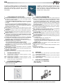
CH
manuale tecnico ventilconvettori a cassette CH
CH water cassette technical manual
VENTILCONVETTORI
FAN COIL UNITS
I
GB
CH
INDEX
INDICE
1
Caratteristiche costruttive ................................................. 3
1
Constructive features .......................................................... 3
2
Versioni costruttive ............................................................ 3
2
Versions ............................................................................... 3
3
Accessori disponibili .......................................................... 3
3
Available accessories ......................................................... 3
4
Caratteristiche tecniche nominali .................................... 4
4
Rated technical data .......................................................... 4
5
Livelli sonori ....................................................................... 5
5
Sound levels ....................................................................... 5
6
Resa raffreddamento ....................................................... 6 - 7
6
Cooling capacity .............................................................. 6 - 7
7
Resa riscaldamento ......................................................... 8 - 9
7
Heating capacity .............................................................. 8 - 9
8
Dimensioni di ingombro ................................................ 10 - 13
8
Overall dimensions ........................................................ 10 - 13
9
Schemi elettrici di collegamento ................................. 14 - 19
9
Wiring diagrams ............................................................. 14 - 19
I dati tecnici e dimensionali riportati nella presente documentazione
possono subire variazioni orientate al miglioramento del prodotto.
SY6600078 - 00
The technical and dimensional data reported in this manual may be modified
in view of any product improvement.
2
È severamente vietata la riproduzione anche parziale di questo manuale / All copying, even partial, of this manual is strictly forbidden
CH
Prodotti in 6 modelli ad 1 batteria e 4 modelli a 2 batterie
i ventilconvettori a cassetta serie CH sono caratterizzati
dalla modu larità 60x60 e 60x120 che si adatta
perfettamente alle pannellature standard dei
controsoffitti.
1
Available in 6 models with one heat exchanger and 4
models with two heat exchangers, the CH series
recess-mounted fan coils are characterised by their
60x60 and 60x120 modularity that perfectly suits
standard false ceiling panels.
CARATTERISTICHE COSTRUTTIVE
1
Batteria di scambio termico in tubo di rame ed alette in alluminio ad
alta efficienza complete di sfiato aria con tubo di drenaggio collegato
alla vasca di raccolta condensa.
Una bacinella raccoglicondensa ausiliaria, fornita di serie, provvede
a raccogliere la condensa generata dalla valvola di regolazione
sull’acqua.
Le macchine vengono fornite di valvola di regolazione a 3 vie / 4
attacchi motorizzate ON/OFF che intercettano acqua fredda e calda su
chiamata del termostato; le valvole sono complete di kit idraulico di
installazione alla batteria di scambio.
Motori elettrici a 3 velocità (1 motore nei modelli 10-20-30, 2 motori
nei modelli 40-50-60) con protettore termico degli avvolgimenti, a basso
numero di giri.
Ventilatore: centrifugo a pale rovesce, estremamente silenzioso,
bilanciato staticamente e dinamicamente, direttamente accoppiato al un
motore a 3 velocità.
Struttura: rivestita esternamente con coibentazione termica e acustica.
L’unità base è predisposta (fori pretranciati) per effettuare una ripresa
di aria esterna e la canalizzazione dell’aria trattata dall’unità ricavati
sul perimetro della struttura portante.
Pompa di scarico condensa: completa di interruttore a galleggiante
per evaquare la condensa dalla bacinella di raccolta e interrompere la
ventilazione in caso di malfunzionamento della pompa stessa.
Componenti elettrici: sono alloggiati in una scatola posta sull’esterno
della struttura portante e sono completi di:
- relè di funzionamento della pompa di scarico condensa
- relè di funzionamento dei ventilatori (modelli 40-50-60)
- morsettiera per la connessione al pannello di comando a parete
MICROPROD che permette la gestione automatica del ventilconvettore
e della valvola di regolazione
Alette deflettrici: l’inclinazione dei deflettori in uscita aria è regolabile
manualmente in tutti i modelli.
Filtro: rigenerabile in materiale sintetico facilmente raggiungibile per le
operazioni di pulizia periodica.
Accessorio obbligatorio
Valvola a 3 vie con kit idraulico per batteria fredda e/o batteria calda.
2
2
VERSIONI COSTRUTTIVE:
water cassette with 1 heat exchanger (2 pipe system) arranged
for MICROPROD controller
CHDF water cassette with 2 heat exchangers (4 pipe system) arranged
for MICROPROD controller
CH R water cassette with 1 heat exchanger (2 pipe system) with
infrared controller
ventilconvettori a cassetta ad 1 batteria (impianto a 2 tubi),
comando a filo in accessorio
CHDF ventilconvettori a cassetta a 2 batteria (impianto a 4 tubi),
comando a filo in accessorio
CH R ventilconvettori a cassetta ad 1 batteria (impianto a 2 tubi)
complete di comando a raggi infrarossi
ACCESSORI DISPONIBILI
-
Pannello di comando a parete MICROPROD
Sonda temperatura acqua SW
Interfaccia di potenza KP
VERSIONS:
CH
CH
3
CONSTRUCTIVE FEATURES
High efficiency heat exchanger made with copper piping and
aluminium fins complete with air release with drainage tube connected
to drip tray. An auxiliary drip tray, fitted as a standard feature, collects
any condensation generated by the water regulation valve. The units
are fitted with motorised ON/OFF 3-way - four connector regulation
valves that intercept cold and hot water as commanded by the
thermostat; the valves are complete with plumbing kits for installation
on the heat exchanger.
Three-speed electric motors (single motor in the 10-20-30 models,
2 motors in the 40-50-60 models) with thermal protector for windings,
with a low number of revolutions.
Fan: centrifugal fan with backward vanes, driven by a three-speed
motor, statically and dynamically balanced, low noise.
Structure: external sound and heat insulation layer. The base unit
has pre-punched holes for fresh air intake and it is arranged for
branch duct flange.
Condensate drainage pump: complete with float switch for draining
the condensate from the drip tray and interrupting ventilation in the event
of a pump malfunction.
Electrical components: housed in a box outside the bearing structure
and complete with:
- condensate drainage pump operation relay
- fun operation relay (models 40-50-60)
- terminal board for connection to the MICROPROD wall- mounted
control panel that allows automatic management of the fan coil and
regulation valve.
Adjustable louvres: the inclination of the air outlet buffles can be
adjusted manually on all models.
Filter: washable, in synthetic material and easily accessible for routine
cleaning.
Obligatory accessory
3-way valve with hydraulic kit for heat-exchanger
3
-
MICROPROD
AVAILABLE ACCESSORIES
Wall mounted control panel MICROPROD
Water probe SW
power interface KP
VK
3
SY6600078 - 00
È severamente vietata la riproduzione anche parziale di questo manuale / All copying, even partial, of this manual is strictly forbidden
CH
4
CARATTERISTICHE TECNICHE NOMINALI
4
RATED TECHNICAL FEATURES
CH
CH10
CH20
CH30
CH40
CH50
Resa totale raffrescamento
Total cooling capacity
max
kW
2,83
3,35
4,81
6,06
7,60
8,48
Resa Raffreddamento Sensibile
Sensible cooloing capacity
max
kW
2,28
2,73
3,69
4,99
6,10
6,38
1448
Portata acqua
Water flow
Perdite di carico lato acqua
Water pressure drop
Resa riscaldamento
Heating capacity
max
CH60
l/h
492
576
830
1034
1312
kPa
12
15
11
13
13
12
kW
6,05
7,09
9,40
12,13
15,71
17,04
1465
Portata acqua
Water flow
l/h
520
610
809
1058
1350
Perdite di carico lato acqua
Water pressure drop
kPa
13
17
12
15
15
13
Contenuto acqua batteria
heat exchanger water content
dm3
1,1
1,5
2,5
2,9
4,2
5,2
Potenza assorbita
Power input
max
W
66
97
143
190
277
277
Corrente assorbita
Current absorbed
max
A
0,30
0,43
0,65
0,83
1,23
1,23
Prevalenza pompa condensa
drain pump head
max
m
0,50
0,50
0,50
0,50
0,50
0,50
Attacchi idraulici
Water connection
mm
22
22
22
22
22
22
max
m3/h
474
570
744
1278
1374
1530
med
m3/h
360
420
564
1020
1206
1062
min
m3/h
318
348
462
930
1020
960
max
dB(A)
57
61
68
64
69
69
med
dB(A)
50
53
59
56
61
61
min
dB(A)
47
47
52
47
56
56
Portata aria
Potenza sonora
Air flow
Sound power
Altezza unità
Unit height
mm
213
263
341
313
313
363
Lunghezza unità
Unit lenght
mm
584
584
584
1089
1089
1089
584
Larghezza unità
Unit width
mm
584
584
584
584
584
Altezza pannello
Panel height
mm
27
27
27
27
27
27
Lunghezza pannello
Panel lenght
mm
625
625
625
1250
1250
1250
Larghezza pannello
Panel width
mm
625
625
625
700
700
700
Peso indicativo
Approx. weight
kg
23
25
27
43
45
48
CH DF
CH20DF
CH30DF
CH40DF
Resa totale raffrescamento
Total cooling capacity
max
kW
2,67
3,93
5,11
CH60DF
6,09
Resa Raffreddamento Sensibile
Sensible cooling capacity
max
kW
2,38
3,30
4,29
4,99
l/h
1031
Portata acqua
Water flow
460
687
868
Perdite di carico lato acqua
Water pressure drop
kPa
9
7
6
10
Contenuto acqua batteria fredda
Cooling coil water content
dm3
1,1
1,8
2,7
3,9
Resa riscaldamento
Heating capcity
kW
3,47
6,24
6,49
8,95
Portata acqua
Water flow
l/h
298
537
558
770
Perdite di carico lato acqua
Water pressure drop
kPa
16
14
17
10
Contenuto acqua batteria calda
heating coil water content
dm3
0,4
0,7
0,9
1,5
Potenza assorbita
Power input
max
W
66
97
143
190
Corrente assorbita
Current absorbed
max
A
0,30
0,43
0,65
0,83
Prevalenza pompa condensa
Drain pump available head
max
m
0,50
0,50
0,50
0,50
Attacchi idraulici
Water connection
-
mm
22
22
22
22
max
m3/h
648
750
1044
1476
med
m3/h
456
528
738
960
min
m3/h
330
402
552
720
max
dB(A)
61
68
64
69
med
dB(A)
53
59
56
60
min
dB(A)
47
52
47
55
Portata aria
Potenza sonora
max
Air flow
Sound power
Altezza unità
Unit height
mm
263
341
313
363
Lunghezza unità
Unit lenght
mm
584
584
1089
1089
Larghezza unità
Unit width
mm
584
584
584
584
Altezza pannello
Panel height
mm
27
27
27
27
Lunghezza pannello
Panel lenght
mm
625
625
1250
1250
Larghezza pannello
Panel width
mm
625
625
700
700
Peso indicativo
Approx. weight
kg
25
29
38
51
Raffreddamento: velocità massima ventilatore, temperatura acqua 7-12°C, temperatura aria 27°C bulbo secco e 19°C bulbo umido
Riscaldamento: velocità massima ventilatore, temperatura acqua 70-60°C, temperatura aria 20°C
SY6600078 - 00
4
È severamente vietata la riproduzione anche parziale di questo manuale / All copying, even partial, of this manual is strictly forbidden
CH
5
LIVELLI SONORI
5
SOUND LEVELS
Vr
Velocità di ventilazione:
3 = massima
2 = media
1 = minima
Livello di potenza sonora per banda di ottava, non ponderato
Livello globale di potenza sonora ponderato A
Livello globale di pressione sonora ponderato A, calcolato alla distanza
di 1,5 m con fattore di direzionalità 2
Vr
Fan speed:
3 = maximum
2 = medium
1 = minimum
Octave band sound power level
A - weighted sound power level
A - weighted sound pressure level (1,5 m distance, 2 directional factor)
Lw
LwA
Lp A
Lw
LwA
Lp A
Lw
Vr
125 Hz
dB
250 Hz
dB
500 Hz
dB
1000 Hz
dB
2000 Hz
dB
4000 Hz
dB
8000 Hz
dB
Lw A
dB/A
Lp A
dB/A
CH 10
3
2
1
52,1
44,9
34,7
57,2
49,5
41,6
55,7
51,1
50,3
52,6
42,9
31,2
48,6
37,3
23,8
41,3
28,0
16,3
30,5
18,6
16,9
57
50
47
45,5
38,5
35,5
CH 20
3
2
1
60,3
53,8
48,0
62,7
54,7
51,1
59,5
52,4
45,7
56,2
48,4
40,7
53,2
43,0
32,3
46,8
34,3
23,5
35,9
22,0
18,1
61
53
47
49,5
41,5
35,5
CH 30
3
2
1
61,5
54,9
54,4
67,1
58,1
53,0
66,9
59,5
51,8
64,2
54,0
47,0
57,6
47,2
39,8
52,6
41,7
32,5
45,0
31,9
21,8
68
59
52
56,5
47,5
40,5
CH 40
3
2
1
62,0
58,1
50,7
64,1
55,0
46,8
63,9
56,2
48,6
59,1
49,5
40,3
55,4
45,1
33,5
50,2
37,8
27,0
41,2
26,2
18,9
64
56
47
52,5
44,5
35,5
CH 50
3
2
1
65,8
59,4
55,4
67,9
60,2
56,7
67,4
59,8
55,5
65,4
56,2
50,9
60,8
51,6
43,7
55,4
45,3
35,9
46,6
34,9
24,3
69
61
56
57,5
49,5
44,5
CH 60
3
2
1
66,8
59,3
55,3
69,2
61,4
54,6
68,6
60,5
54,6
65,0
54,9
49,4
59,6
50,6
44,2
55,1
44,4
36,6
46,1
34,5
24,7
69
61
56
57,5
49,5
44,5
Vr
125 Hz
dB
250 Hz
dB
500 Hz
dB
1000 Hz
dB
2000 Hz
dB
4000 Hz
dB
8000 Hz
dB
Lw A
dB/A
Lp A
dB/A
CH 20 DF
3
2
1
60,4
53,5
48,4
62,0
55,9
49,4
59,1
53,1
46,4
57,4
48,7
38,9
53,6
43,8
32,3
47,0
34,7
21,7
35,8
22,5
18,1
61
53
47
49,5
41,5
35,5
CH 30 DF
3
2
1
62,1
55,1
49,4
69,1
57,6
52,7
68,9
60,9
55,1
66,7
54,8
46,4
57,6
47,5
40,8
52,1
40,4
31,4
43,5
30,5
20,6
68
59
52
56,5
47,5
40,5
CH 40 DF
3
2
1
60,8
55,7
49,9
64,6
56,7
49,8
66,6
67,3
57,3
60,5
52,1
44,0
56,1
47,1
37,8
50,4
38,0
27,5
39,5
25,2
18,7
64
56
47
52,5
44,5
35,5
CH 40 DF
3
2
1
66,6
59,3
58,2
70,9
61,0
54,3
68,4
61,2
58,1
64,9
54,9
48,1
60,1
50,3
42,8
54,9
43,9
34,8
45,8
33,6
23,0
70
61
56
58,5
49,5
44,5
Lw
5
SY6600078 - 00
È severamente vietata la riproduzione anche parziale di questo manuale / All copying, even partial, of this manual is strictly forbidden
CH
6
RESE IN RAFFREDDAMENTO
6
Legenda:
Tbs1
Temperatura ingresso aria bulbo secco
Tbu1
Temperatura ingresso aria bulbo umido
Tw1
Temperatura ingresso acqua
Tw2
Temperatura uscita acqua
Vr
Velocità di ventilazione:
3
massima
2
media
1
minima
PFT
Potenzialità raffreddamento totale
PFS
Potenzialità raffreddamento sensibile
Qw
Portata acqua
' pw
Perdita di carico lato acqua
COOLING CAPACITY
Legend:
Inlet air temperature dry bulb
Tbs1
Tbu1
Inlet air temperature wet bulb
Tw1
Inlet water temperature
Tw2
Outlet water temperature
Vr
Fan speed:
3
high
2
medium
1
low
PFT
Total cooling capacity
PFS
Sensible cooling capacity
Qw
Water flow rate
' pw
Pressure drop on water side
Tbs1 / Tbu1 (UR1)
25°C / 18°C (51%)
Tw1 / Tw2
6 / 11°C
7°C / 12°C
8°C / 13°C
9°C / 14°C
Vr
PFT
W
PFS
W
Qw
l/h
' pw
kPa
PFT
W
PFS
W
Qw
l/h
' pw
kPa
PFT
W
PFS
W
Qw
l/h
' pw
kPa
PFT
W
PFS
W
Qw
l/h
' pw
kPa
CH 10
3
2
1
2680
2070
1780
2080
1590
1380
0,128
0,099
0,085
11
7
5
2210
1680
1590
1890
1430
1310
0,105
0,08
0,076
8
5
4
1710
1480
1410
1710
1360
1240
0,082
0,071
0,067
5
4
3
1590
1360
1260
1590
1360
1260
0,076
0,065
0,06
4
3
3
CH 20
3
2
1
3210
2550
2180
2500
1920
1610
0,153
0,122
0,104
14
10
7
2790
2190
1850
2330
1770
1470
0,133
0,105
0,088
11
7
5
2310
1740
1580
2150
1590
1370
0,11
0,083
0,075
8
5
4
1840
1500
1370
1840
1500
1290
0,088
0,072
0,066
5
4
3
CH 30
3
2
1
4610
3700
3280
3430
2680
2360
0,22
0,176
0,156
10
7
6
4020
3190
2820
3190
2470
2170
0,192
0,152
0,135
8
5
4
3340
2690
2520
2920
2270
2040
0,159
0,128
0,12
6
4
4
2640
2340
2200
2640
2130
1920
0,126
0,112
0,105
4
3
3
CH 40
3
2
1
5770
4930
4590
4610
3870
3590
0,275
0,235
0,219
12
9
8
4910
4100
3750
4280
3550
3260
0,234
0,196
0,179
9
7
6
3580
3210
3250
3580
3210
3070
0,171
0,153
0,155
5
4
4
3330
2990
2860
3330
2990
2860
0,159
0,143
0,136
5
4
4
CH 50
3
2
1
7110
5840
5570
5600
4490
4200
0,339
0,278
0,266
12
8
8
5850
5260
5030
5100
4260
3980
0,279
0,251
0,24
8
7
6
5170
4670
4470
4850
4030
3750
0,247
0,222
0,213
7
5
5
4630
4050
3890
4630
3800
3530
0,221
0,193
0,185
5
4
4
CH 60
3
2
1
7860
6820
6290
5830
4990
4490
0,374
0,325
0,3
11
8
7
6800
6150
5680
5420
4710
4240
0,324
0,293
0,271
8
7
6
6020
5460
5060
5120
4440
3990
0,287
0,26
0,241
7
6
5
5220
4750
4410
4820
4170
3740
0,249
0,226
0,21
5
4
4
Tbs1 / Tbu1 (UR1)
27°C / 19°C (47%)
Tw1 / Tw2
6 / 11°C
7°C / 12°C
8°C / 13°C
9°C / 14°C
Vr
PFT
W
PFS
W
Qw
l/h
' pw
kPa
PFT
W
PFS
W
Qw
l/h
' pw
kPa
PFT
W
PFS
W
Qw
l/h
' pw
kPa
PFT
W
PFS
W
Qw
l/h
' pw
kPa
CH 10
3
2
1
3230
2560
2280
2410
1870
1660
0,154
0,122
0,109
15
10
8
2830
2210
1950
2250
1730
1520
0,135
0,106
0,093
12
8
6
2370
1760
1620
2070
1550
1400
0,113
0,084
0,077
9
5
4
1910
1550
1440
1910
1550
1330
0,091
0,074
0,069
6
4
4
CH 20
3
2
1
3740
3000
2580
2850
2190
1850
0,178
0,143
0,123
19
13
10
3350
2670
2290
2690
2060
1740
0,16
0,127
0,109
15
10
8
2920
2320
1970
2530
1920
1600
0,139
0,11
0,094
12
8
6
2190
1890
1610
2190
1760
1470
0,104
0,09
0,077
7
6
4
CH 30
3
2
1
5360
4320
3860
3900
3060
2710
0,255
0,206
0,184
14
9
8
4810
3870
3440
3680
2870
2530
0,229
0,184
0,164
11
8
6
4220
3360
2970
3440
2670
2340
0,201
0,16
0,141
9
6
5
3540
2750
2570
3180
2430
2180
0,169
0,131
0,123
6
4
4
CH 40
3
2
1
6840
5900
5530
5290
4460
4150
0,326
0,281
0,263
17
13
12
6060
5200
4860
4990
4190
3890
0,289
0,248
0,232
13
10
9
5200
4410
4080
4670
3890
3590
0,248
0,21
0,194
10
8
7
3990
3420
3260
3990
3420
3260
0,19
0,163
0,155
6
5
4
CH 50
3
2
1
8760
6990
6310
6560
5190
4710
0,417
0,333
0,301
17
11
9
7600
5960
5690
6100
4780
4460
0,362
0,284
0,271
13
8
8
6090
5370
5130
5530
4550
4240
0,29
0,256
0,245
9
7
6
5270
4760
4560
5270
4320
4020
0,251
0,227
0,217
7
6
5
CH 60
3
2
1
9850
7920
7030
6920
5670
5000
0,469
0,377
0,335
16
11
9
8480
6970
6420
6380
5290
4760
0,404
0,332
0,306
12
9
8
6940
6280
5800
5790
5020
4510
0,331
0,299
0,277
9
7
6
6140
5570
5160
5500
4760
4260
0,293
0,266
0,246
7
6
5
SY6600078 - 00
6
È severamente vietata la riproduzione anche parziale di questo manuale / All copying, even partial, of this manual is strictly forbidden
CH
6
RESE IN RAFFREDDAMENTO
6
COOLING CAPACITY
Legend:
Tbs1
Inlet air temperature dry bulb
Tbu1
Inlet air temperature wet bulb
Tw1
Inlet water temperature
Tw2
Outlet water temperature
Vr
Fan speed:
3
high
2
medium
1
low
PFT
Total cooling capacity
PFS
Sensible cooling capacity
Qw
Water flow rate
' pw
Pressure drop on water side
Legenda:
Tbs1
Temperatura ingresso aria bulbo secco
Tbu1
Temperatura ingresso aria bulbo umido
Tw1
Temperatura ingresso acqua
Tw2
Temperatura uscita acqua
Vr
Velocità di ventilazione:
3
massima
2
media
1
minima
PFT
Potenzialità raffreddamento totale
PFS
Potenzialità raffreddamento sensibile
Qw
Portata acqua
' pw
Perdita di carico lato acqua
Tbs1 / Tbu1 (UR1)
25°C / 18°C (51%)
Tw1 / Tw2
6 / 11°C
7°C / 12°C
8°C / 13°C
9°C / 14°C
Vr
PFT
W
PFS
W
Qw
l/h
' pw
kPa
PFT
W
PFS
W
Qw
l/h
' pw
kPa
PFT
W
PFS
W
Qw
l/h
' pw
kPa
PFT
W
PFS
W
Qw
l/h
' pw
kPa
CH 20 DF
3
2
1
2510
1870
1590
2180
1620
1280
0,12
0,089
0,076
9
5
4
1800
1610
1430
1800
1520
1220
0,086
0,077
0,068
5
4
3
1660
1420
1270
1660
1420
1160
0,079
0,067
0,06
4
3
3
1540
1320
1120
1540
1320
1120
0,074
0,063
0,053
4
3
2
CH 30 DF
3
2
1
3700
2530
2460
3030
1910
1820
0,176
0,121
0,117
6
3
3
2890
2290
2220
2720
1810
1730
0,138
0,109
0,106
4
3
2
2530
2030
1970
2530
1710
1630
0,12
0,097
0,094
3
2
2
2360
1770
1720
2360
1600
1530
0,113
0,084
0,082
3
2
2
CH 40 DF
3
2
1
4810
4170
3610
3940
3150
2590
0,229
0,199
0,172
5
4
3
4310
3750
3270
3740
2990
2440
0,205
0,179
0,156
4
3
3
3800
3330
2910
3550
2820
2300
0,181
0,159
0,139
3
3
2
3580
2890
2540
3580
2650
2150
0,171
0,138
0,121
3
2
2
CH 60 DF
3
2
1
5680
4450
3930
4560
3450
2900
0,271
0,212
0,187
9
6
5
4660
4000
3550
4180
3270
2750
0,222
0,191
0,169
6
5
4
4010
3540
3150
4010
3100
2590
0,191
0,169
0,15
5
4
3
3740
3040
2740
3740
3040
2440
0,178
0,145
0,131
4
3
2
Tbs1 / Tbu1 (UR1)
27°C / 19°C (47%)
Tw1 / Tw2
6 / 11°C
7°C / 12°C
8°C / 13°C
9°C / 14°C
Vr
PFT
W
PFS
W
Qw
l/h
' pw
kPa
PFT
W
PFS
W
Qw
l/h
' pw
kPa
PFT
W
PFS
W
Qw
l/h
' pw
kPa
PFT
W
PFS
W
Qw
l/h
' pw
kPa
CH 20 DF
3
2
1
3080
2410
1820
2540
1920
1450
0,147
0,115
0,087
12
8
5
2670
2040
1630
2380
1780
1370
0,127
0,097
0,078
9
6
4
2000
1600
1460
2000
1600
1310
0,096
0,076
0,07
6
4
3
1850
1510
1270
1850
1510
1270
0,088
0,072
0,061
5
3
3
CH 30 DF
3
2
1
4530
2840
2750
3530
2130
2030
0,216
0,135
0,131
8
4
3
3930
2590
2510
3300
2030
1930
0,187
0,123
0,12
7
3
3
3210
2330
2270
3030
1930
1840
0,153
0,111
0,108
5
3
2
2690
2070
2010
2690
1830
1740
0,128
0,099
0,096
3
2
2
CH 40 DF
3
2
1
6370
4670
4040
4780
3510
2880
0,303
0,222
0,192
9
5
4
5110
4250
3690
4290
3350
2740
0,243
0,203
0,176
6
4
3
4380
3820
3340
4020
3180
2590
0,209
0,182
0,159
4
3
3
4070
3390
2970
4070
3020
2450
0,194
0,162
0,142
4
3
2
CH 60 DF
3
2
1
7070
5060
4400
5360
3880
3230
0,337
0,241
0,21
13
7
6
6090
4550
4020
4990
3680
3080
0,29
0,217
0,192
10
6
5
4800
4090
3620
4530
3510
2930
0,229
0,195
0,173
7
5
4
4270
3620
3220
4270
3340
2780
0,204
0,173
0,154
5
4
3
7
SY6600078 - 00
È severamente vietata la riproduzione anche parziale di questo manuale / All copying, even partial, of this manual is strictly forbidden
CH
7
RESA RISCALDAMENTO
7
HEATING CAPACITY
Legenda:
Tbs1
Temperatura ingresso aria bulbo secco
Tw1
Temperatura ingresso acqua
Tw2
Temperatura uscita acqua
Vr
Velocità di ventilazione:
3
massima
2
media
1
minima
PT
Potenzialità termica resa
Qw
Portata acqua
' pw
Perdita di carico lato acqua
Legend:
Inlet air temperature dry bulb
Tbs1
Tw1
Inlet water temperature
Tw2
Outlet water temperature
Vr
Fan speed:
3
high
2
medium
1
low
PT
Heating capacity
Qw
Water flow rate
' pw
Pressure drop on water side
Le resa termica dei ventilconvettori con ventilatore fermo è da considerare, con buona
approssimazione, pari al 10% della resa termica di progetto.
The fan coil heating capacity with fan switched off has to be considered equal to
about 10% of the theoretical design heating capacity, with good approximation.
Tbs1
22°C
Tw1 / Tw2
45 / 40°C
60°C / 50°C
70°C / 60°C
90°C / 70°C
Vr
PT
W
Qw
l/h
' pw
kPa
PT
W
Qw
l/h
' pw
kPa
PT
W
Qw
l/h
' pw
kPa
PT
W
Qw
l/h
' pw
kPa
CH 10
3
2
1
3050
2490
2250
0,147
0,12
0,109
10
7
6
4770
3900
3540
0,116
0,095
0,086
6
4
4
6170
5040
4580
0,15
0,123
0,112
10
7
6
8290
6800
6190
0,102
0,083
0,076
5
3
3
CH 20
3
2
1
3560
2870
2480
0,172
0,138
0,12
15
10
8
5580
4500
3900
0,135
0,109
0,095
9
6
5
7200
5780
5010
0,175
0,141
0,122
14
9
7
9670
7820
6800
0,119
0,096
0,083
7
5
4
CH 30
3
2
1
4670
3830
3450
0,226
0,185
0,167
9
7
6
7320
6010
5430
0,178
0,146
0,132
6
4
3
9430
7740
6990
0,23
0,189
0,17
9
6
5
12690
10470
9460
0,156
0,128
0,116
4
3
3
CH 40
3
2
1
6140
5390
5090
0,297
0,26
0,246
13
10
9
9570
8400
7940
0,232
0,204
0,193
8
6
6
12420
10900
10300
0,303
0,266
0,251
12
10
9
16540
14560
13780
0,203
0,179
0,169
6
5
4
CH 50
3
2
1
7850
6600
6150
0,379
0,319
0,297
13
10
8
12260
10320
9630
0,298
0,25
0,234
8
6
5
15950
13440
12540
0,389
0,328
0,306
12
9
8
21320
17990
16810
0,262
0,221
0,206
6
4
4
CH 60
3
2
1
8470
7260
6460
0,409
0,35
0,312
10
8
6
13210
11330
10100
0,321
0,275
0,245
6
5
4
17240
14790
13170
0,42
0,361
0,321
10
8
6
22990
19750
17630
0,282
0,242
0,216
5
4
3
Tbs1
22°C
Tw1 / Tw2
45 / 40°C
60°C / 50°C
70°C / 60°C
90°C / 70°C
Vr
PT
W
Qw
l/h
' pw
kPa
PT
W
Qw
l/h
' pw
kPa
PT
W
Qw
l/h
' pw
kPa
PT
W
Qw
l/h
' pw
kPa
CH 10
3
2
1
2760
2250
2040
0,133
0,109
0,099
9
6
5
4480
3650
3320
0,109
0,089
0,081
6
4
3
5880
4800
4360
0,143
0,117
0,106
9
6
5
7980
6550
5950
0,098
0,08
0,073
4
3
3
CH 20
3
2
1
3230
2600
2250
0,156
0,126
0,109
12
8
7
5240
4230
3660
0,127
0,103
0,089
8
6
4
6850
5510
4770
0,167
0,134
0,116
13
9
7
9320
7530
6550
0,114
0,092
0,08
6
4
3
CH 30
3
2
1
4240
3470
3130
0,205
0,168
0,151
8
6
5
6870
5650
5100
0,167
0,137
0,124
5
4
3
8980
7380
6660
0,219
0,18
0,162
8
6
5
12230
10080
9110
0,15
0,124
0,112
4
3
2
CH 40
3
2
1
5570
4880
4610
0,269
0,236
0,223
11
9
8
8980
7880
7450
0,218
0,191
0,181
7
6
5
11830
10380
9820
0,288
0,253
0,239
11
9
8
15940
14030
13280
0,195
0,172
0,163
5
4
4
CH 50
3
2
1
7100
5970
5560
0,343
0,288
0,269
11
8
7
11490
9670
9020
0,279
0,235
0,219
7
5
5
15180
12790
11930
0,37
0,312
0,291
11
8
7
20530
17310
16160
0,252
0,212
0,198
6
4
4
CH 60
3
2
1
7660
6550
5830
0,37
0,317
0,282
9
7
5
12380
10610
9450
0,3
0,257
0,229
6
4
4
16430
14070
12530
0,4
0,343
0,305
9
7
6
22130
19000
16960
0,271
0,233
0,208
4
3
3
SY6600078 - 00
8
È severamente vietata la riproduzione anche parziale di questo manuale / All copying, even partial, of this manual is strictly forbidden
CH
7
RESA RISCALDAMENTO
7
HEATING CAPACITY
Legenda:
Tbs1
Temperatura ingresso aria bulbo secco
Tw1
Temperatura ingresso acqua
Tw2
Temperatura uscita acqua
Vr
Velocità di ventilazione:
3
massima
2
media
1
minima
PT
Potenzialità termica resa
Qw
Portata acqua
' pw
Perdita di carico lato acqua
Legend:
Inlet air temperature dry bulb
Tbs1
Tw1
Inlet water temperature
Tw2
Outlet water temperature
Vr
Fan speed:
3
high
2
medium
1
low
PT
Heating capacity
Qw
Water flow rate
' pw
Pressure drop on water side
Le resa termica dei ventilconvettori con ventilatore fermo è da considerare, con buona
approssimazione, pari al 10% della resa termica di progetto.
The fan coil heating capacity with fan switched off has to be considered equal to
about 10% of the theoretical design heating capacity, with good approximation.
Tbs1
22°C
Tw1 / Tw2
45 / 40°C
60°C / 50°C
70°C / 60°C
90°C / 70°C
Vr
PT
W
Qw
l/h
' pw
kPa
PT
W
Qw
l/h
' pw
kPa
PT
W
Qw
l/h
' pw
kPa
PT
W
Qw
l/h
' pw
kPa
CH 20 DF
3
2
1
1710
1460
1260
0,082
0,071
0,061
17
13
10
2640
2270
1950
0,064
0,055
0,047
10
8
6
3470
2980
2560
0,085
0,073
0,062
16
12
9
4550
3920
3370
0,056
0,048
0,041
7
6
4
CH 30 DF
3
2
1
3070
2550
2180
0,148
0,123
0,105
15
11
8
4770
3970
3400
0,116
0,096
0,082
9
7
5
6240
5180
4410
0,152
0,126
0,108
14
10
8
8250
6870
5880
0,101
0,084
0,072
7
5
4
CH 40 DF
3
2
1
3190
2720
2360
0,154
0,132
0,114
17
13
10
4930
4220
3660
0,12
0,102
0,089
11
8
6
6490
5540
4790
0,158
0,135
0,117
17
13
10
8520
7300
6340
0,104
0,089
0,078
8
6
5
CH 60 DF
3
2
1
4420
3630
3140
0,213
0,175
0,152
10
7
6
6850
5640
4870
0,166
0,137
0,118
6
5
3
8950
7360
6380
0,218
0,179
0,155
10
7
5
11810
9750
8460
0,145
0,12
0,104
5
3
3
Tbs1
22°C
Tw1 / Tw2
45 / 40°C
60°C / 50°C
70°C / 60°C
90°C / 70°C
Vr
PT
W
Qw
l/h
' pw
kPa
PT
W
Qw
l/h
' pw
kPa
PT
W
Qw
l/h
' pw
kPa
PT
W
Qw
l/h
' pw
kPa
CH 20 DF
3
2
1
1540
1330
1140
0,074
0,064
0,055
14
11
8
2470
2130
1830
0,06
0,052
0,044
9
7
5
3300
2830
2430
0,08
0,069
0,059
15
11
9
4380
3770
3250
0,054
0,046
0,04
7
5
4
CH 30 DF
3
2
1
2780
2310
1970
0,134
0,112
0,095
12
9
7
4480
3730
3190
0,109
0,09
0,077
8
6
4
5940
4930
4200
0,145
0,12
0,102
13
9
7
7940
6620
5670
0,097
0,081
0,069
6
4
3
CH 40 DF
3
2
1
2880
2460
2130
0,139
0,119
0,103
15
11
9
4620
3960
3430
0,112
0,096
0,083
9
7
6
6170
5270
4560
0,15
0,128
0,111
15
12
9
8200
7020
6100
0,101
0,086
0,075
7
6
4
CH 60 DF
3
2
1
4000
3280
2830
0,193
0,159
0,137
9
6
5
6430
5280
4570
0,156
0,128
0,111
6
4
3
8530
7010
6070
0,208
0,171
0,148
9
6
5
11380
9400
8140
0,139
0,115
0,1
4
3
2
9
SY6600078 - 00
È severamente vietata la riproduzione anche parziale di questo manuale / All copying, even partial, of this manual is strictly forbidden
CH
8
DIMENSIONI DI INGOMBRO
8
Legenda
1
ingresso acqua
2
uscita acqua
3
scarico condensa
4
scatola collegamento elettrici
5
canalizzazione aria trattata
6
ingresso aria esterna
OVERALL DIMENSIONS
Legenda
1
water inlet
2
water outlet
3
drain pipe
4
eletrical box
5
branch duct conneciton
6
fresh air inlet
CH 10
36
27
241
4
100
3
2
111
52
5
1
21
21
625
3
2
36
92
5
133
52
CH 20
39
291
4
27
1
CH 30
2
3
118
211
36
52
5
27
1
39
369
4
CH 10 - 20 - 30
99
427
99
OPEN
=
OPEN
554
625
=
6
SY6600078 - 00
10
È severamente vietata la riproduzione anche parziale di questo manuale / All copying, even partial, of this manual is strictly forbidden
CH
DIMENSIONI DI INGOMBRO
8
Legenda
1
ingresso acqua
2
uscita acqua
3
scarico condensa
4
scatola collegamento elettrici
5
canalizzazione aria trattata
6
ingresso aria esterna
OVERALL DIMENSIONS
Legenda
1
water inlet
2
water outlet
3
drain pipe
4
eletrical box
5
branch duct conneciton
6
fresh air inlet
3
1
5
4
105
2
27
30
133
263
53
5
35
CH 40
80
1090
80
3
1
5
4
53
162
2
27
30
313
183
5
35
CH 40 - 50 - 60
80
1090
80
CH 40 - 50 - 60
1250
136
978
136
6
45
151
OPEN
OPEN
OPEN
302
535
625
172
= 45
6
OPEN
8
585
50
600
600
11
SY6600078 - 00
È severamente vietata la riproduzione anche parziale di questo manuale / All copying, even partial, of this manual is strictly forbidden
CH
8
DIMENSIONI DI INGOMBRO
8
Legenda
1
ingresso acqua batteria acqua fredda
1DF
ingresso acqua batteria acqua calda
2
uscita acqua batteria acqua fredda
2DF
uscita acqua batteria acqua calda
3
scarico condensa
4
scatola collegamento elettrici
5
canalizzazione aria trattata
6
ingresso aria esterna
OVERALL DIMENSIONS
Legend
1
chilled water inlet
1DF
hot water inlet
2
chilled water outlet
2DF
hot water outlet
3
drain pipe
4
eletrical box
5
branch duct conneciton
6
fresh air inlet
2
3
36
27
291
4
156
2DF
105
5
133
52
CH DF 20
1
25
1DF
25
625
3
2
133
27
291
4
156
2DF
105
5
36
52
CH DF 30
1
1DF
CH DF 20 - 30
99
427
99
OPEN
=
OPEN
554
625
=
6
SY6600078 - 00
12
È severamente vietata la riproduzione anche parziale di questo manuale / All copying, even partial, of this manual is strictly forbidden
CH
DIMENSIONI DI INGOMBRO
8
Legenda
1
ingresso acqua batteria acqua fredda
1DF
ingresso acqua batteria acqua calda
2
uscita acqua batteria acqua fredda
2DF
uscita acqua batteria acqua calda
3
scarico condensa
4
scatola collegamento elettrici
5
canalizzazione aria trattata
6
ingresso aria esterna
OVERALL DIMENSIONS
Legend
1
chilled water inlet
1DF
hot water inlet
2
chilled water outlet
2DF
hot water outlet
3
drain pipe
4
eletrical box
5
branch duct conneciton
6
fresh air inlet
CH DF 40
2DF
5
5
4
105
35
53
1
27
30
133
263
2
3
1DF
80
1090
80
2DF
5
2
3
53
162
4
27
30
363
183
5
1
1DF
35
CH DF 60
80
1090
80
CH DF 40 - 60
1250
136
978
136
6
45
151
OPEN
OPEN
OPEN
302
535
625
172
= 45
6
OPEN
8
585
50
600
600
13
SY6600078 - 00
È severamente vietata la riproduzione anche parziale di questo manuale / All copying, even partial, of this manual is strictly forbidden
CH
9
SCHEMI ELETTRICI DI COLLEGAMENTO
9
WIRING DIAGRAMS
CH 10 - 20 - 30
CH 10 - 20 - 30
Legend
WH
BK
BU
RD
PK
GY
GP
R
PC
MV
T
CH
F
Bianco
Nero
Blu
Rosso
Rosa
Grigio
Galleggiante pompa di scarico condensa
Relè
pompa di scarico condensa
motore ventilatore
trasformatore 230V - 24V
morsettiera cassetta
fusibile di protezione
White
Black
Blue
Red
Pink
Grey
Condensate drainage pump float
Relay
Condensate drainage pump
Fan motor
230V - 24V transformer
cassette terminal board
protection fuse
SY6600078 - 00
5
3
R1
6
4
R1
6
BK
5
4
GY
RD
3
2
BU
BK
1
PK
L
N
WH
F
220V.
T
WH
WH
24V.
2
R1
GP
6
7
R1
BK
8
PC
WH
BN
MV
Legenda
WH
BK
BU
RD
PK
GY
GP
R
PC
MV
T
CH
F
14
È severamente vietata la riproduzione anche parziale di questo manuale / All copying, even partial, of this manual is strictly forbidden
CH
SCHEMI ELETTRICI DI COLLEGAMENTO
9
WIRING DIAGRAMS
CH 40 - 50 - 60
CH 40 - 50 - 60
Legend
WH
BK
BU
RD
PK
GY
GP
R
PC
MV
T
CH
F
White
Black
Blue
Red
Pink
Grey
Condensate drainage pump float
Relay
Condensate drainage pump
Fan motor
230V - 24V transformer
cassette terminal board
protection fuse
5
R1
6
4
R1
R1
2
24V.
9
14
13
R4
14
R3
13
15
6
5
BK
GY
4
RD
3
2
BU
BK
1
PK
L
WH
F
13
R2
14
220V.
5
5
T
R4
9
WH
RD
BU
R3
5
R2
9
BK
WH
GP
6
7
BK
R1
8
PC
WH
BN
BN
WH
MV
MV
Bianco
Nero
Blu
Rosso
Rosa
Grigio
Galleggiante pompa di scarico condensa
Relè
pompa di scarico condensa
motore ventilatore
trasformatore 230V - 24V
morsettiera cassetta
fusibile di protezione
N
Legenda
WH
BK
BU
RD
PK
GY
GP
R
PC
MV
T
CH
F
3
9
SY6600078 - 00
È severamente vietata la riproduzione anche parziale di questo manuale / All copying, even partial, of this manual is strictly forbidden
CH
9
SCHEMI ELETTRICI DI COLLEGAMENTO
9
WIRING DIAGRAMS
CH + MICROPROD + VK
CH + MICROPROD + VK
Legenda
WH
BK
BU
RD
PK
GY
GP
R
PC
MV
T
CH
VK
MICROPROD
SW
F
IL
Legend
WH
BK
BU
RD
PK
GY
GP
R
PC
MV
T
CH
VK
MICROPROD
SW
F
IL
Bianco
Nero
Blu
Rosso
Rosa
Grigio
Galleggiante pompa di scarico condensa
Relè
pompa di scarico condensa
motore ventilatore
trasformatore 230V - 24V
morsettiera cassetta
valvola motorizzata 3 vie/4 attacchi
pannello di comando a parete
sonda temperatura acqua
fusibile di protezione
interruttore di linea
230/1/50
White
Black
Blue
Red
Pink
Grey
Condensate drainage pump float
Relay
Condensate drainage pump
Fan motor
230V - 24V transformer
cassette terminal board
3-way motor driven valve, 4 connections
wall-mounted control panel
water temperature probe
protection fuse
main switch
N
F
L
MICROPRO-D
N
V3
L
V2
1
V1
L
2
PE
3
N
N
RE
4
V
RM
SA
5
RM
EX
6
EX
SW
SY6600078 - 00
VK
16
È severamente vietata la riproduzione anche parziale di questo manuale / All copying, even partial, of this manual is strictly forbidden
CH
9
SCHEMI ELETTRICI DI COLLEGAMENTO
9
WIRING DIAGRAMS
CHDF + MICROPROD + VK
CHDF + MICROPROD + VK
Legenda
WH
BK
BU
RD
PK
GY
GP
R
PC
MV
T
CH
MICROPROD
SW
F
IL
VKC
VKH
Legend
WH
BK
BU
RD
PK
GY
GP
R
PC
MV
T
CH
MICROPROD
SW
F
IL
VKC
VKH
Bianco
Nero
Blu
Rosso
Rosa
Grigio
Galleggiante pompa di scarico condensa
Relè
pompa di scarico condensa
motore ventilatore
trasformatore 230V - 24V
morsettiera cassetta
pannello di comando a parete
sonda temperatura acqua
fusibile di protezione
interruttore di linea
valvola fredda
valvola calda
White
Black
Blue
Red
Pink
Grey
Condensate drainage pump float
Relay
Condensate drainage pump
Fan motor
230V - 24V transformer
cassette terminal board
wall-mounted control panel
water temperature probe
protection fuse
main switch
cold water valve
hot water valve
N
230/1/50
F
L
CHDF
MICROPRO-D
N
V3
L
V2
1
V1
L
2
PE
3
N
N
RE
4
V
RM
SA
5
RM
EX
6
EX
VKC
VKH
SW
17
SY6600078 - 00
È severamente vietata la riproduzione anche parziale di questo manuale / All copying, even partial, of this manual is strictly forbidden
CH
Legend
WH
BK
BU
RD
PK
GY
GP
R
PC
MV
T
CH
VK
KVK
MICROPROD
SW
EXT
F
IL
RHC
KP
6
4
5
VK
K-VK
1
2
3
L
N
6
VK
K-VK
1
2
3
4
5
CH
White
Black
Blue
Red
Pink
Grey
Condensate drainage pump float
Relay
Condensate drainage pump
Fan motor
230V - 24V transformer
cassette terminal board
3-way motor driven valve, 4 connections
valve relay
wall-mounted control panel
water temperature probe
external auxiliary contact
protection fuse
main switch
remote manual summer/winter selecting switch
power interface
CH
L
N
6
4
5
L
N
L
N
K-VK
RM
RM
2
3
4
5
13
14
15
16
C
1
2
3
KP
3A 250V
RELE' DI POTENZA
POWER RELAY
1
2
30
27
28
29
3A 250V
3
RELE' DI POTENZA
POWER RELAY
3A 250V
RELE' DI POTENZA
POWER RELAY
4
26
23
24
25
VK
K-VK
1
2
3
6
L
N
4
5
22
19
20
21
VK
K-VK
1
2
3
WIRING DIAGRAMS
nr. 4 CH + KP + MICROPROD + VK
CH
Bianco
Nero
Blu
Rosso
Rosa
Grigio
Galleggiante pompa di scarico condensa
Relè
pompa di scarico condensa
motore ventilatore
trasformatore 230V - 24V
morsettiera cassetta
valvola motorizzata 3 vie/4 attacchi
relè valvola
pannello di comando a parete
sonda temperatura acqua
contatto ausiliario esterno
fusibile di protezione
interruttore di linea
selettore stagionale manuale remoto
interfaccia di potenza
CH
Legenda
WH
BK
BU
RD
PK
GY
GP
R
PC
MV
T
CH
VK
KVK
MICROPROD
SW
EXT
F
IL
RHC
KP
9
L
N
SCHEMI ELETTRICI DI COLLEGAMENTO
n° 4 CH + KP + MICROPROD + VK
34
31
32
33
9
RM
RM
EXT
MICROPROD
MICROPRO
230V 1 50Hz
IL
230V 1 50Hz
CRHC
SW
N
L
L
N
SA
MICROPROD
IL
V3
V2
V1
L
PE
N
N
N
RE
V
RM
RM
EX
EX
F
F
RHC
SY6600078 - 00
18
È severamente vietata la riproduzione anche parziale di questo manuale / All copying, even partial, of this manual is strictly forbidden
CH
SCHEMI ELETTRICI DI COLLEGAMENTO
9
WIRING DIAGRAMS
nr. 4 CHDF + KP + MICROPROD + VK
Legend
WH
BK
BU
RD
PK
GY
GP
R
PC
MV
T
CH
MICROPROD
SW
EXT
F
IL
RHC
KP
KVH
KVC
VC
VH
CH
6
VH
K-VH
4
5
VC
K-VC
1
2
3
6
VH
K-VH
VC
L
N
L
N
RM
RM
EXT
MICROPROD
K-VH
RM
RM
K-VC
2
3
4
5
13
14
15
16
C
1
2
3
KP
3A 250V
RELE' DI POTENZA
POWER RELAY
1
2
34
31
32
33
VH
K-VC
1
2
3
4
5
CH
White
Black
Blue
Red
Pink
Grey
Condensate drainage pump float
Relay
Condensate drainage pump
Fan motor
230V - 24V transformer
cassette terminal board
wall-mounted control panel
water temperature probe
external auxiliary contact
protection fuse
main switch
remote manual summer/winter selecting switch
power interface
hot water valve relay
cold water valve relay
cold water valve
hot water valve
CH
6
L
N
4
5
K-VH
30
27
28
29
3A 250V
3A 250V
RELE' DI POTENZA
POWER RELAY
3
26
23
24
25
VC
K-VC
1
2
3
L
N
6
RELE' DI POTENZA
POWER RELAY
4
22
19
20
21
VH
K-VH
4
5
VC
K-VC
1
2
3
CH
Bianco
Nero
Blu
Rosso
Rosa
Grigio
Galleggiante pompa di scarico condensa
Relè
pompa di scarico condensa
motore ventilatore
trasformatore 230V - 24V
morsettiera cassetta
pannello di comando a parete
sonda temperatura acqua
contatto ausiliario esterno
fusibile di protezione
interruttore di linea
selettore stagionale manuale remoto
interfaccia di potenza
relè valvola calda
relè valvola fredda
valvola fredda
valvola calda
L
N
n° 4 CHDF + KP + MICROPROD + VK
Legenda
WH
BK
BU
RD
PK
GY
GP
R
PC
MV
T
CH
MICROPROD
SW
EXT
F
IL
RHC
KP
KVH
KVC
VC
VH
L
N
MICROPRO
IL
230V 1 50Hz
CRHC
SW
19
N
L
L
N
SA
MICROPROD
IL
V3
V2
V1
L
PE
N
N
N
RE
V
RM
RM
EX
EX
F
F
RHC
230V 1 50Hz
9
SY6600078 - 00
È severamente vietata la riproduzione anche parziale di questo manuale / All copying, even partial, of this manual is strictly forbidden
40010 Bentivoglio (BO)
Via Romagnoli, 12/a
Tel. 051/8908111
Fax 051/8908122
www.galletti.it