1
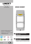
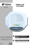
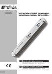
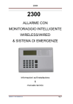
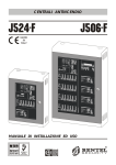
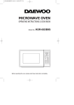
8014-ISR010
8072-ISR054
ART. / ITEM:
8014-ISR010
8072-ISR054
IT
RIVELATORE DA INTERNO IN DOPPIA
TECNOLOGIA VIA RADIO
Manuale di installazione, uso e manutenzione
EN
DUAL TECHNOLOGY WIRELESS DETECTOR FOR
INDOOR USE
Installation, operation and maintenance manual
MADE IN ITALY
ITALIANA SENSORI S.A.s
- Istruzioni originali -
- Translation of the original instructions (original instructions in Italian) -
INDICE
CONTENTS
1. CARATTERISTICEH GENERALI....................................................................... 2
2. CARATTERISTICHE TECNICHE....................................................................... 3
3.AVVERTENZE.................................................................................................... 3
4. IDENTIFICAZIONE DELLE PARTI.................................................................... 3
5.INSTALLAZIONE............................................................................................... 4
5.1 CON SNODO.......................................................................................... 4
5.2 SENZA SNODO...................................................................................... 4
6. MEMORIZZAZIONE ......................................................................................... 5
7. FUNZIONE TEST............................................................................................... 5
8.SUPERVISIONE................................................................................................. 5
9. INIBIZIONE......................................................................................................... 6
10. GRAFICO DI COPERTURA............................................................................... 6
11. MANUTENZIONE E VERIFICHE PERIODICHE................................................ 7
11.1 PULIZIA ESTERNA DEL RILEVATORE.................................................. 7
12. SMALTIMENTO E ROTTAMAZIONE................................................................. 7
12.1DISINSTALLAZIONE............................................................................... 7
1. GENERAL FEATURES...................................................................................... 2
2. TECHNICAL FEATURES................................................................................... 3
3.NOTICES ........................................................................................................... 3
4. PARTS IDENTIFICATION................................................................................... 3
5.INSTALLATION.................................................................................................. 4
5.1 WITH BRACKET..................................................................................... 4
5.2 WITHOUT BRACKET.............................................................................. 4
6.STORAGE.......................................................................................................... 5
7. TEST FUNCTION............................................................................................... 5
8.MONITORING..................................................................................................... 5
9. STADN-BY MODE.............................................................................................. 6
10. COVERED AREA PATTERN.............................................................................. 6
11. MAINTENANCE AND PERIODIC CHECKS...................................................... 7
11.1 CLEANING THE EXTERNAL PART OF THE DETECTOR..................... 7
12. DISPOSAL AND SCRAPPING........................................................................... 7
12.1DISMANTLING........................................................................................ 7
Le informazioni riportate in questo manuale sono state compilate
con cura, tuttavia Italiana Sensori non può essere ritenuta
responsabile per eventuali errori e/o omissioni. Italiana Sensori si
riserva il diritto di apportare in ogni momento, e senza preavviso,
miglioramenti e/o modifiche ai prodotti descritti nel presente
manuale.
Italiana Sensori pone particolare attenzione al rispetto
dell’ambiente. Tutti i prodotti ed i processi produttivi sono
progettati con criteri di eco-compatibilità. Il presente articolo è
stato prodotto in Italia.
The informations in this manual have been issued with care,
anyway Italiana Sensori will not be responsible for any errors
or omissions. Italiana Sensori reserves the rights to improve or
modify the products described in this manual at any times and
without advance notice.
Italiana Sensori pays particular attention to environment respect.
Each product and each process have been designed with ecocompatibility criteria.
This product has been made in Italy.
1. CARATTERISTICHE GENERALI
1. GENERAL FEATURES
•
•
•
•
•
•
•
•
•
•
•
•
•
Doppia trasmissione dell’evento “DTE”;
Funzionamento in abbinamento al ricevitore universale
8012-ISA001
Basso consumo di corrente, alimentazione con batteria al
litio;
Circuito di rilevazione batteria scarica;
Sensore dual PIR + microonda a 10,525 GHz;
Lente di Fresnel anti UV;
Funzione TEST della durata di 4 minuti durante i quali il
rilevatore effettua una trasmissione ad ogni rilevazione
senza andare in inibizione;
Microinterruttore antisabotaggio a protezione del coperchio
con lente;
Tre tipi di trasmissione radio: ALLARME, SABOTAGGIO E
BATTERIA SCARICA;
Codice digitale a 72 bit.
2. CARATTERISTICHE TECNICHE
8014-ISR010
•
•
•
2. TECHNICAL FEATURES
8014-ISR010
8072-ISR054
8072-ISR054
Batteria al litio AA 3,6 V
(codice 001510/00206AA)
Power supply
AA Lithium battery 3,6 V
(item: 001510/00206AA)
Corrente nominale
13 uA
Rated current
13 uA
Corrente massima
25 mA
Maximum current
Alimentazione
Frequenza MW
10,525 GHz
MW frequency
Frequenza TX
868,3 MHz
TX frequency
Portata Radio (aria libera)
100 m
Wireless range (free air)
Portata di rilevazione
12 m
Detection range
Copertura orizzontale
Temperatura di eserzio
Peso (solo rilevatore)
2
•
•
•
•
•
“DTE” Double Transmission of Event
Working in conjunction with the universal receiver 8012ISA001
Low power consumption, powered by lithium battery;
Low battery detection circuit;
Dual PIR sensor + Microwave at 10.525 GHz;
Fresnel lens, anti UV;
TEST function lasting 4 minutes during which the detector
makes a transmission for every detection without going
inhibition;
Anti-tamper micro-switch to protect cover with lens;
Three types of wireless transmissions: ALARM, TAMPER
AND LOW BATTERY;
72-bit digital code.
90°
6°
Horizontal coverage
25 mA
10,525 GHz
868,3 MHz
100 m
12 m
90°
6°
5°÷ 40°C
Operating temperature
5°÷ 40°C
110 g
Weight (only detector)
110 g
ITALIANA SENSORI S.A.s
3.AVVERTENZE
•
•
•
•
•
E’ buona norma prima di installare il rilevatore fare un’attenta
valutazione dell’area da proteggere evitando zone cieche
nell’area di rilevazione (mobili, scaffalature, etc…).
Evitare che oggetti in movimento invadano l’area da
proteggere (tende finestre, etc…).
Evitare la presenza di animali nell’area protetta.
Installare il rilevatore su un supporto stabile e privo di
vibrazioni.
Non installare il sensore all’esterno.
4. IDENTIFICAZIONE DELLE PARTI
Part.
3.NOTICES
•
•
•
•
•
It is good practice to carefully assess the area to be protected
before installing the detector, avoiding any blind spots in the
area surveyed (furniture, shelves, etc ...).
Prevent moving objects from invading the area to be
protected (curtains windows, etc ...).
Prevent animals from entering the protected area.
Install the detector on a stable and vibration free support.
Do not install the sensor outside.
4. PARTS IDENTIFICATION
Identificazione
Ref.
Identification
A
Gambo dello snodo
A
Bracket arm
B
Collare in alluminio
B
Aluminum collar
C
Viti M3 per fissaggio snodo
C
M3 bracket mounting screws
D
Fondo del rilevatore
D
Detector base
E
Scheda elettronica
E
Electronic board
F
Microinterruttore antiapertura
F
Anti-tamper micro-switch
G
Trimmer regolazione sensibilità della microonda
G
Microwave sensitivity adjustment Trimmer
H
Viti parker fissaggio scheda elettronica
H
Board mounting screws
I
Frontale con lente di Fresnel
I
Front panel with Fresnel lens
A
A
D
B
G
C
I
H
F
E
Fig. 1
3
ITALIANA SENSORI S.A.s
P
P
R
N
N
P
P
Fig. 2
5.INSTALLAZIONE
5.INSTALLATION
Per il montaggio a parete si consiglia un’altezza di installazione
compresa tra 2,1 m e 2,3 m. Lo snodo del rilevatore permette
installazioni a soffitto e/o ad altezze superiori a quelle consigliate;
in questi casi occorre inclinare opportunamente il rilevatore per
adattare al meglio il campo di copertura alle effettive necessità.
For wall mounting the recommended height is between 2.1 m
and 2.3 m. The detector bracket means that it can be installed
on the ceiling and/or at heights above those recommended; in
these cases the detector should be tilted in a suitable manner
to adapt the field of coverage to actual needs.
5.1
5.1
•
•
•
•
•
5.2
•
SENZA SNODO
Aprire il rilevatore facendo leva sugli agganci elastici
presenti sul frontale con lente;
Svitare le due viti parker (I) ed asportare la scheda
elettronica (E);
Inserire il tappo copriforo (R) sulla parte posteriore del fondo
del rilevatore;
Per fissare il rilevatore, sfondare le predisposizioni (N)
per montaggio a parete o (P) per montaggio ad angolo,
utilizzando uno strumento appuntito (può essere sufficiente
un cacciavite a croce);
Collegare la batteria (vedi capitolo memorizzazione) e
chiudere il rlevatore facendo attenzione che gli scatti
automatici siano incastrati.
CON SNODO
Fissare il gambo dello snodo (fig. 1 A) sul muro o sul soffitto
utilizzando il tassello in dotazione;
• Aprire il rilevatore facendo leva sugli agganci elastici (H);
• Svitare le due viti parker (I) ed asportare la scheda elettronica
(E);
• Inserire il gambo dello snodo (A) nel collare di alluminio (B), far
aderire il tutto con la parte posteriore del fondo del rilevatore
(D) quindi fissare a pacchetto i tre particolari, utilizzando le due
viti metriche (C);
• Orientare il rilevatore nella direzione che garantisca la
copertura desiderata;
• Terminato l’orientamento, bloccare il movimento dello snodo
serrando le due viti (C);
• Rimontare la scheda elettronica (E) fissandola con le viti
parker (I);
• Inserire la batteria (vedi capitolo relativo alla memorizzazione).
9. inibizone
4
•
•
•
•
•
5.2
•
•
•
•
•
•
•
•
•
WITHOUT BRACKET
Open the detector by levering the elastic hooks on the front
panel with lens
Remove the two screws (I) and take out the electronic
board (E)
Insert the plug cover (R) on the rear of the detector base
To fix the detector, break through the points provided
(N) for wall mounting or (P) for corner mounting, using a
pointed tool (a Phillips screwdriver may be sufficient);
Connect the battery (see chapter on Storage) and close
the detector, making sure that the automatic snap-on
elements are in place.
WITH BRACKET
Fasten the arm of the bracket (fig. 1 A) to the wall or ceiling
using the plug provided
Open the detector by levering the elastic hooks (H)
Remove the two screws (I) and take out the electronic
board (E)
Insert the arm of the bracket (A) into the aluminum collar
(B), ensure that everything adheres to the rear of the
detector base (D) then secure the three parts in a pack,
using the two metric screws (C).
Turn the detector in the direction that ensures the desired
coverage
After adjusting the direction, block movement of the
bracket by locking the two screws (C)
Mount the electronic board (E) using the screws (I)
Insert the battery (see the chapter on storage)
Close the detector by inserting the cover with Fresnel lens
ITALIANA SENSORI S.A.s
6. MEMORIZZAZIONE
6. STORAGE
Per la procedura di memorizzazione, inserire la pila quando
richiesto dal manuale della ricevente utilizzata.
For the storage procedure, place the battery when required by
manual of the uesed receiver.
7. FUNZIONE TEST
7. TEST FUNCTION
Tale funzione è stata implementata per facilitare la configurazione
del rilevatore. Si può attivare togliendo il coperchio (la
successiva chiusura non provoca cambiamenti di stato);
entro un minuto la funzione verrà attivata. In questa condizione i
LED si attiveranno ed avranno il seguente significato:
• LED Rosso: si accende ad ogni trasmissione radio sia essa
un sabotaggio che una rilevazione di allarme
• LED Giallo: si accende ogni qualvolta la microonda rileva
un movimento
• LED Verde: si accende ogni qualvolta il PIR rileva un
movimento
Dopo circa 4 minuti il rilevatore esce automaticamente dalla
modalità test, i LED vengono disattivati e viene attivata la
funzione di inibizione (vedi capitolo 8 in seguito).
This function was implemented to facilitate configuration of
the detector. This can be activated by removing the cover
(closing it again will not cause any change in state); within
one minute the function will be activated. In this condition, the
LEDs will light up and will have the following meanings:
NOTE:
1. i LED saranno attivi esclusivamente quando il rilevatore è
in modalità test;
2. Al termine del test i LED saranno in modalità sempre
spento, per riattivarli al fine di verificare il funzionamento del
rilevatore, occorre aprire e richiudere la copertura con lente
(apertura e chiusura dell’antisabotaggio).
3. Per provare la zona di copertura del rilevatore è importante
che il sensore sia chiuso e con la copertura con lente di
Fresnel inserita.
4. Una volta effettuate le prove di rilevazione e copertura radio
il rilevatore è pronto per il funzionamento, al termine della
fase di test il funzionamento del rielvatore potrà essere
verificato in accordo con il sistema radio al quale è collegato.
NOTE:
1. the LEDs will only light up when the detector is in test mode;
2. When the test is completed the LEDs will be in permanent
off mode, to turn them on in order to check that the detector
is working you must open and re-close the cover with lens
(open and close anti-tampering device).
3. To test the detector coverage area it is important that the
sensor be closed and the cover with Fresnel lens be inserted.
4. Once the detection and wireless range tests are completed
the sensor is ready to operate. At the end of testing,
operation of the detector can be checked according to the
wireless system to which it is connected.
8. SUPERVISIONE
8. MONITORING
La supervisione è utile per aumentare il livello di sicurezza
dell’impianto; i rilevatori con tale funzione attivata inviano, ad
intervalli regolari, un breve segnale di esistenza in vita alla
ricevente. Di default la funzione di supervisione non è attiva sul
rivelatore; per attivarla occorre effettuare una procedura durante
la fase di “self-test” iniziale.
Il lampeggio dei LED nel “self- test” iniziale avviene nel seguente
modo (supervisione disattiva):
• 1 lampeggio LED rosso,
• 1 lampeggio LED verde,
• 1 lampeggio LED giallo.
Per attivare la supervisione premere velocemente tre volte
il microswitch di antisabotaggio entro i 30 secondi di self- test
iniziale (F – Fig 1) e verificare che i tre LED lampeggino nel
seguente modo:
• 2 lampeggi LED rosso,
• 2 lampeggi LED verde,
• 2 lampeggi LED giallo.
Per disattivare la supervisione, eseguire la stessa azione
utilizzata per attivarla.
Monitoring is usefull to improve the security system; the
detectors with this function activated send, at regulars intevals,
a short signal of “ existence in life” to the receveir. By default
the monitoring function is not active on the detector; for activate
the function is necessary follow a sequence during the power-on
self-test phase.
The LEDs flashing during the power-on self-test takes place in
the following way (monitoring disabled):
•
1 flash of the red LED,
•
1 flash of the green LED,
•
1 fash of the yellow LED.
NOTE:
1. Le impostazioni della supervisione rimangono memorizzate
anche se la pila viene rimossa.
2. per verificare lo stato della funzione servirsi delle
segnalazioni dei LED durante la fase di self-test.
3. per attivare la fase di self-test, successivamente alla
prima attivazione del rilevatore, togliere la pila per qualche
secondo e re-inserirla.
4. é necessario attivare la supervisione sulla ricevente facendo
riferimento al relativo manuale.
NOTES:
1. The monitoring settings are kept in the device memory even
in case of battery removal.
2. To verify if the function status, use the LEDs signals of the
power-on self test.
3. To activate again the self-test after the first activation of the
device, remove the battery for a few seconds and insert it
again.
4. It is mandatory to activate the monitoring function referring
to the product manual.
•
Red LED: lights up with each wireless transmission,
whether it involve tampering or alarm detection.
• Yellow LED: lights up each time the microwave detects a
movement
• Green LED: lights up each time the PIR detects a movement
After about 4 minutes the detector will automatically exit the test
mode, the LEDs are turned off and stand-by mode is activated
(see chapter 8 below).
To activate the monitoring function press quickly three times the
tamper during the 30 seconds of power-on self-test (F- Fig. 1)
and verify that the three LEDs flashing as follow:
•
2 flashes of the red LED,
•
2 flashes of the green LED,
•
2 flashes of the yellow LED.
For disabling the monitoring function, carry out the same action
used for activate it.
5
ITALIANA SENSORI S.A.s
9 INIBIZIONE
9 STAND-BY MODE
Nel funzionamento normale (LED spenti) il rilevatore attiva
automaticamente la funzione INIBIZIONE per risparmiare
batteria, questo comporta che, se l’ambiente è frequentato,
il rilevatore rimanga inibito fino a quando non sussisteranno
almeno 3 minuti di quiete (nessuna rilevazione).
Questa importante funzione evita che il rilevatore trasmetta di
continuo situazioni di allarme ad ogni passaggio di persone.
Per verificare il funzionamento del rilevatore quindi occorre
attendere almeno tre minuti senza alcuna rilevazione.
In normal operating mode (LEDs off) the detector automatically
switches to STAND-BY to save on battery, this means that, if
the area is in use, the sensor will remain in stand-by mode until
there is at least 3 minutes of quiet (no detection).
This important feature ensures that the detector does not send
out a continuous alarm each time a person passes. To test the
detector it is therefore necessary to wait at least three minutes
without any movement being detected.
10. GRAFICO DI COPERTURA
10. COVERED AREA PATTERN
8014-ISR010
8072-ISR054
VISTA IN PIANTA / PLAN VIEW
VISTA LATERALE / SIDE VIEW
Fig. 3
6
ITALIANA SENSORI S.A.s
11.MANUTENZIONE E VERIFICHE PERIODICHE
11.
MAINTENANCE
CHECKS
11.1 PULIZIA ESTERNA DEL RILEVATORE
11.1 CLEANING THE EXTERNAL PART OF THE DETECTOR
Per assicurare il corretto funzionamento del rilevatore è necessario che la lente venga mantenuta pulita. Una lente non
perfettamente pulita può causare problemi di rivelazioni e/o
problemi alla funzione antimask.
AND
PERIODIC
Keep the lens clean to guarantee proper operation of the
detector.
A lens which is not perfectly clean may cause detection problems and/or problems to the anti-mask function.
Periodicità: quando necessario o in condizione di sporcizia evidente.
Materiale da utilizzare: panno - acqua senza additivi.
Procedura di pulizia:
Frequency: when necessary or when clearly dirty.
Material to be used: cloth - water with no additives.
Cleaning procedure:
IMPORTANT!
Do NOT use chlorine-based or abrasive products or
alcohol to remove particularly noticeable dirt.
ATTENZIONE! Per rimuovere sporcizie particolarmente evidenti NON utilizzare prodotti a base di cloro, prodotti abrasivi oppure alcool.
1.Pulire il coperchio e la lente con un panno inumidito con acqua.
2. Ripassare con un panno asciutto.
1. Clean the lid and the lens with a cloth dampened with water.
2. 2. Wipe with a dry cloth.
12.SMALTIMENTO E ROTTAMAZIONE
12.DISPOSAL AND SCRAPPING
12.1DISINSTALLAZIONE
12.1DISMANTLING
ATTENZIONE!
Non disperdere nell’ambiente i componenti ed ogni
altro materiale del prodotto.
Rivolgersi a consorzi abilitati allo smaltimento ed al riciclaggio dei materiali.
IMPORTANT!
Do not dispose of the components or any other product material in the environment.
Seek the assistance of companies authorised to dispose of
and recycle waste materials.
1. Rimuovere il coperchio frontale
2. Rimuovere la pila.
3. Dividere le parti in base alla loro tipologia e smaltirle in accordo con le leggi vigenti.
1. Remove the front lid.
2. Disconnect the battery.
3.Divide the parts by type and dispose of them in accordance
with applicable laws.
7
001530/00321SD
Italiana Sensori S.a.s.
Via Pordenone, 2
00100 Roma (RM)
tel. +39 06 92928252
fax +39 06 92942586
[email protected]
www.italianasensori.it