1
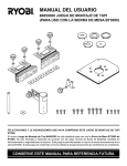
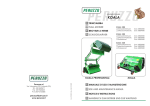
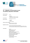
manuale di installazione, uso e manutenzione
MANUALE DI
INSTALLAZIONE
USO E
MANUTENZIONE
REGOLATORE ELETTRONICO DIGITALE DI VELOCITA’ CON MICROPROCESSORE
ELECTRONIC DIGITAL SPEED CONTROLLER WITH MICROPROCESSOR
REGULATEUR ELECTRONIQUE DE VITESSE DIGITAL AVEC MICROPROCESSEUR
ELEKTRONISCHER DIGITALE DREHZAHLREGLER MIT MIKROPROZESSOR
RE600
Pagina 1 di 5
manuale di installazione, uso e manutenzione
Indicatore valore velocità aspiratore da 1 a 9
Display ventilator’s speed value from 1 to 9
Vitesse de ventilateur variable 1 a 9
Anzeiger - Display Geschwindigkeit von 1 bis 9
Pulsanti per selezione massima velocità
Push botton for selection of tha max. speed
Bouton pour la vitesse maximum
Taste fuer der max. Geschwindigkeit
Interruttore lampada
Light switch
Interrupteur de lumiere
Schalter fuer Lampe
Pulsanti regolazione velocità aspiratore
Push buttons regulation of ventilator’s speed
Règlage vitesse ventilateur
Geschwindigkeit Regulierungs-Taste
Interruttore aspiratore
Ventilator switch
Interrupteur ventilateur
Schalter fuer Ventilator
ISTRUZIONI DI COLLEGAMENTO
Morsetto 3
collegare i cavi di terra
Morsetto 5 -6
collegare il motore
Morsetti 7 - 8
collegare la lampada
Morsetti 9 -10
collegare elettrovalvola del gas (se presente)
Morsetto 2
cavo di terra della linea di alimentazione
Morsetti 1 - 4
cavi di alimentazione 230Vac
Morsettiera gruppo comandi
Control unit terminal board
Domino du variateur de vitesse
Klemmbrett der Steuerungengruppe
CONNECTING INSTRUCTIONS
Terminal 3
connect the earthing cables
Terminal 5 - 6
connect the motor
Terminals 7 - 8
connect the lamp
Terminals 9 -10
connect the gas electric valve (if present)
Terminal 2
earthing cable of the alimentation line
Terminals 1 - 4
alimentation cables 230Vac
INTRUCTIONS GENERALES
Etrier 3
raccorder les cables de terre
Etrier 5 - 6
fixer le cable de ventilateur
Etriers 7- 8
raccordement le cable de lumiere
Etriers 9-10
raccordement electrovanne de gaz (si necessaire)
Etrier 2
ligne cable de terre (courant)
Etriers 1 - 4
alimentation générale de courant 230Vac
VERBINDUNGSANWEISUNGEN
Klemme 3
verbinden Sie die Erdungskabels
Klemme 5 - 6
verbinden Sie den Ventilator
Klemme 7 - 8
verbinden Sie die Lampe
Klemme 9 - 10
verbinden Sie das Elektroventil des Gas (wenn es gibt)
Klemme 2
Erdungskabel der Speisungsleitung
Klemme 1 - 4
230Vac Speisungskabels
1 2
3
4
5 6
7
8
9 10
230 Vac
M
Gas
Pagina 2 di 5
manuale di installazione, uso e manutenzione
DATI TECNICI
TECHNICAL DATA
DATES TECHNIQUE
TECHNISCHE DATEN
Alimentazione
Current supply
Alimentation
Speisung
Potenza nominale
Nominal power
Puissance nominale
Nominale Leistung
Corrente in servizio continuo
Continuous service current
Courant de service continu
Dauernder Strom
Corrente massima di spunto
Max. current
Courant maxi
Max. Strom
Fusibile di protezione
Protection fuse
Fusible de protection
Schmelzsicherungschutz
Circuito di controllo
Checking circuit
Circuit de controle
Kontrollschaltung
Pre-taratura minima velocità
Pre-calibration min. speed
Pre controle minimum de vitesse
Voreichung der min. Geschwindigkeit
Regolazione minima velocità
Adjustment range of the minimum speed
Reglage de vitesse mini
Regelung der min. Geschwindigkeit
Regolazione della massima velocità
Adjustment range of the maximum speed
Reglage de vitesse maxi
Regelung der max. Geschwindigkeit
Protezione sovratensione
Extra current protection
Protection extra courent
Extrastromschutz
Interrruttore lampada
Light switch
Interrupteur lumiere
Schalter fuer Lampe
Grado di protezione del contenitore
Protection degree of the box
Degrè de protection de la boite
Schutzgrad des Behaelters
Dimensioni
Dimensions
Dimensions
Groesse
230 / 50 / 1
2000W
8A
13A
10A (ritardato)
Microprocessore
50% (della massima)
Automatica
80% - 100% in 2 steps
Varistore
Unipolare
IP 55
162x119x73 mm
ISTRUZIONI DI FUNZIONAMENTO
Premere il pulsante di accensione dell’aspiratore
Pagina 3 di 5
manuale di installazione, uso e manutenzione
In tal modo l’aspiratore inizia ad operare alla massima velocità impostata ,come indicato dalla cifra “9” sul display, per portasi dopo circa 10
secondi al valore regolato nella precedente accensione.
Se necessario, è possibile a questo punto agire sui pulsanti “+” e “-” per variare la velocità dell’aspiratore.
Trascorsi 20 secondi dall’accensione dell’aspiratore viene comandata l’apertura della valvola del gas (se collegata)
OPERATING INSTRUCTIONS
Push the button of the ventilator’s start.
In this case the ventilator starts to work at the max. selected speed, as indicated by the digit “9” on the display.In 10 seconds will the ventilator’s start go
on the value regulated in the previous starting.In case it is necessary, it is possible at this step to act on the buttons (+ or -) in order to change the
ventilator’s speed.
After 20 seconds from the ventilator’s starting, the opening of the gas valve will be commanded. (when connected)
INSTRUCTIONS SPECIFIQUES
Appuyer le buoton de ventilateur, suite le ventilateur il marche a la maximum vitesse, sur le display il va a sortie le numero “9”, aprers 10 secondes
retourne a la vitesse dejàen memorie.
Ce necessarie est possible changer la vitesse de ventilateur sur le bouton (+ et -)
Après 20 secondes, ouvertures automatique de la electrovanne du gas.
FUNKTIONSANWEISUNGEN
Druecken Sie die - ein - Drucktaste des Ventilators um den Drehzahlregler in Betrieb zu nehmen.
Nach dem Einschalten schaltet sich der Ventilator auf seine maximale Stellung, lesbar am Display ( Zahl “9”).
Nach gegen 10 Sekunden wird der Ventilator sich auf den zuletzt eingeschalteten Wert schalten
Sie koennen je nach Bedarf mit der (+) Taste die Geschwindigkeit erhoehen und mit der (-) Taste die Geschwindigkeit verringern, lesbar am Display.
20 Sekunden nach dem Einschalten ist die Oeffung des Elektroventil des Gas geoeffnet (wenn es abgeschlossen ist).
ISTRUZIONI PER L’IMPOSTAZIONE DELLA MASSIMA VELOCITA’
Dare tensione al regolatore: il display indicherà il valore “0”
Tenere premuto per 25 secondi circa il tasto “0” dell’interruttore luce.
Trascorso questo periodo il display mostrerà un punto decimale.
- Agendo ora sul tasto “+” il display mostrerà il numero “9” indicante la massima velocità pari al 100% di quella raggiungibile.
- Agendo invece sul tasto “-” il display mostrerà il numero “8” indicante la massima velocità pari al 80% di quella raggiungibile
Premere il tasto “0” dell’interruttore luce per confermare la scelta effettuata.
Premere il tasto “1” dell’interruttore luce per uscire dalla procedura di impostazione della massima velocità.
INSTRUCTIONS FOR THE SELECTION OF THE MAX. SPEED
Give tension to the speed controller: the display will indicate the value “0”
Push the button “0” of the light switch for 25 seconds
After this period of time the display will show you a decimal point.
- When you push the button “+”, the display will show you the number “9” indicating the max speed same as to the 100% of the achievable.
- At the contrary when you push the button “-”, the display will show you the number “8” indicating the max speed same as to the 80% of the achievable
Push the button “0” of the light switch to confirm your choice
Push the button “1” of the light switch to go out from the max. speed selection’s procedure.
INSTRUCTION POUR LA VITESSE MAXIMUM
Donnez courant a le variateur le display valeur “0”
Appuyer pour 25 seconds le bouton “0” de la lumiere, apres le period sur le display une point decimale
- sur le bouton “+” le display numero”9” pour la maximum vitesse pair au 100%.
- sur le bouton “-” le display numero”8” pour la maximum vitesse pair au 80%.
Appuyer le bouton “0” de la lumiere pour confimez la vitesse.
Appuyer le bouton “1” de la lumiere pour sortie da la impostation de la maximun vitesse.
STELLUNGSANWEISUNGEN DER MAX. GESCHWINDIGKEIT
Geben Sie Spannung auf den Regler: Zahl “0” lesbar am Display.
Druecken Sie fuer gegen 25 Sekunden den Schalter fuer Lampe “0”: einen Dezimalspunkt wird am Display lesbar sein.
- Wenn Sie jetzt die Taste “+” druecken, wird am Display die Zahl “9” lesbar sein: es zeigt die max. Geschwindigkeit gleich als 100% der erreichbar
- Wenn Sie dagegen die Taste “-” druecken, wird am Display die Zahl “8” lesbar sein: es zeigt die max. Geschwindigkeit gleich als 80% der erreichbar
- Druecken Sie den Schalter fuer Lampe “0”, um Ihre Auswahl zu bestaetigen.
- Druecken Sie den Schalter fuer Lampe “1”, um aus der max. Geschwindigkeit zu gehen.
AVVERTENZE E LIMITI DI UTILIZZO
Verificare che i dati della rete di alimentazione ed il carico da applicare rientri nei parametri di targa del regolatore
Assicurarsi che le viti dei morsetti di collegamento siano serrate.
Verificare che le viti di chiusura della scatola ed i passacavi siano ben serrati
Limiti di utilizzo: temperatura max. 70°C
Pagina 4 di 5
manuale di installazione, uso e manutenzione
CAUTIONS AND USE LIMITS
Check that the datas of the current supply net and the load (current)to apply are within the parameters of the speed controller plate.
Check that the screws of the connecting terminals are locked.
Check that the closing screws of the box and the cable’s rings are well locked..
Use limits: 70°C temperature
INSTRUCTIONS SPECIFIQUE
Verifier que la portèe electrique de l’installation et de la prise de courant corresponde a la puissance max de l’appareil indiquè sur la plaquette du
ventilateur.
Functionament a temperature ambiante max 70°C
HINWEISEN UND GEBRAUCHSBEGRENGUNGEN
Pruefen Sie, dass die Daten des Speisungsnetz und die Leistung zu setzen in der Parameter des Schild des Reglers hineingehoeren sind.
Pruefen Sie, dass die Schrauben der Verbindungsklemmen geschlossen sind.
Pruefen Sie, dass die Schluss-schrauben der Schachtel und die Kabelsringen gut geschlossen sind.
Gebrauchsbegrebgungen: max. Temperatur 70° C
ATTENZIONE
•
•
•
•
•
E’ OBBLIGATORIO PORRE UN’INTERRUTORE DI SICUREZZA BIPOLARE A MONTE DEL REGOLATORE
L’INSTALLAZIONE DEVE ESSERE EFFETTUATI DA PERSONALE QUALIFICATO PROFESSIONALMENTE NEL SETTORE DEI COMPONENTI
ELETTRICI AD USO CIVILE ED INDUSTRIALE
QUESTO APPARECCHIO DEVE ESSERE DESTINATO SOLO ALL’USO PER IL QUALE È STATO ESPRESSAMENTE PREVISTO.
E’ PERTANTO ESCLUSA QUALUNQUE RESPONSABILITÀ’ DEL COSTRUTTORE PER DANNI CAUSATI DA UN USO IMPROPRIO
QUESTO LIBRETTO COSTITUISCE PARTE INTEGRANTE ED ESSENZIALE DEL PRODOTTO
ATTENTION
•
•
•
•
•
IT IS COMPULSORY TO PLACE A BIPOLAR SAFETY SWITCH IN THE CURRENT SUPPLY LINE BEFORE THE SPEED CONTROLLER
(SWITCH - SPEED CONTROLLER - VENTILATOR/LAMP)
THE INSTALLATION MUST BE CARRIED OUT BY QUALIFIED PROFESSIONAL PERSONNEL WITH TECHNICAL EXPERTISE IN THE FIELD
OF THE ELECTRIC COMPONENTS FOR CIVIL AND INDUSTRIAL USE
THIS DEVICE MUST BE DESTINATED TO THE USE IT HAS BEEN FORESEEN FOR.
SO THE MANUFACTURER DECLINES ANY RESPONSABILITY FOR DAMAGES CAUSED BY AN INCORRECT USE
THIS BOOKLET IS AN ESSENTIAL AND INTEGRATE PART OF THE PRODUCT
ATTENTION
•
•
•
•
•
OBBLIGATOIRE UNE INTERRUPTEUR DE SECURITE’ BIPOLAIRE
L’INSTALLATION DEVRA ETRE EFFECTUEE EXCLUSIVEMENT PAR PERSONNEL QUALIFIE’, AVEC COMPETENCE TECHNIQUE
SPECIFIQUE DANS LE DOMAINE DES ELECTRIQUES A’ EMPLOI CIVIL ET INDUSTRIEL
CET APPAREIL DEVRA ETRE DESTINE’ SEULEMENT A’ L’EMPLOI POUR LEQUEL IL A ETE’ PREVU
LE CONSTRUCTEUR DECLINE TOUTE RESPONSABILITE’ POUR LES DOMMAGES CAUSES PAR DES FAUTES D’ EMPLOI
CE DOSSIER CONSTITUE UNE PARTIE INTEGRANTE ET ESSENTIELLE DU PRODUIT
ACHTUNG
•
•
•
•
•
ES IST VORGESCHRIEBEN DIE INSTALLATION EINEN ZWEIPOLARE SICHEREITSSCHALTER VOR DES REGLERS IN DER
SPEISUNGSLEITUNG (SICHEREITSSCHALTER - REGLER - VENTILATOR/LAMPE)
DIE INSTALLIERUNG MUSS DURCH QUALIFIZIERTES PERSONAL, MIT SPEZIFISCHEN TECHNISCHE KOMPETENZ IM BEREICH DER
ELEKTRISCHEN ELEMENTE FUER ZIVILE UND INDUSTRIELLE ZWECKE, ERFOLGEN
DIESES GERAET IST NUR FUER BESTIMMTE ZWECKE VORGESEHEN
DADURCH UEBERNIMMT DER HERSTELLER KEINE VERANTWORTUNG FUER SCHAEDEN, DIE DURCH NICHT KORREKTEN GEBRAUCH
ENTSTEHEN
DIESES BUCH INTEGRIERT EINEN WESENTLICHEN TEIL DES PRODUKTES
Pagina 5 di 5