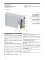
1
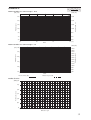
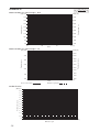
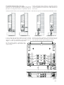
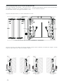
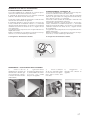
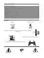
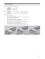
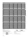
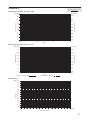
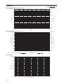
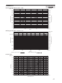
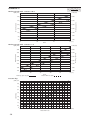
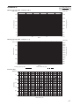
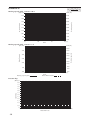
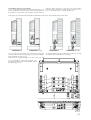
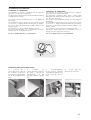
MANUALE UNICO
B O O K L E T
TERMOCONVETTORE
THERMOCONVECTOR
CLIMAFON
ISO 9001 - Cert. n° 0128/4
sostituisce:
6181400_01P 0602
ICLIMAFONUW
0706
P R E L I M I N A R E 6181400_02P
INDICE
Trasporto • Simboli di sicurezza
Informazioni generali • Descrizione dell’unità
Caratteristiche di CLIMAFON
Componenti principali • Descrizione dei componenti
Versioni disponibili
Dati tecnici
Dati dimensionali • Limiti di funzionamento • Imballo
Potenza termica resa • Perdite di carico
Installazione dell'unità
Installazione dell'unità in un nuovo impianto
Installazione dell'unità per sostituzione dei radiatori
Versione con aletta automatica
Manutenzione • Problemi e soluzioni
Servizio Assistenza Tecnica Italia
3
4
5
6
7
8
9
10
22
23
26
27
28
31
TRASPORTO
NON bagnare
NON calpestare
Sovrapponibilità: controllare sull’imballo la posizione della freccia per conoscere il
numero di macchine impilabili
6
5
4
3
2
1
NON lasciare gli imballi sciolti durante il trasporto
NON trasportare la macchina da soli se il suo peso supera i 35 Kg.
35 Kg
SIMBOLI DI SICUREZZA
Pericolo:
Tensione
Pericolo:
Organi in movimento
Pericolo!!!
3
Termoconvettore CLIMAFON
Desideriamo complimentarci con Voi per la scelta del termoconvettore “CLIMAFON” Aermec.
Realizzato con materiali di qualità superiore e tecnologie innovative, nel rigoroso rispetto delle
più avanzate e severe normative di sicurezza, CLIMAFON sostituisce con facilità il tradizionale
radiatore, superandone i noti limiti.
Il termoconvettore “CLIMAFON” Aermec è un corpo scaldante per impianti ad acqua calda
per il riscaldamento degli ambienti.
DESCRIZIONE DELL’UNITÀ
Il termoconvettore CLIMAFON concentra elevate caratteristiche tecnologiche e funzionali che ne
fanno il terminale ideale per il riscaldamento di ogni
ambiente.
CLIMAFON non necessita di collegamento elettrico.
L’erogazione di calore avviene per convezione naturale, grazie ad un esclusivo scambiatore alettato.
L’erogazione di calore è immediata e distribuita in
modo uniforme in tutto il locale; CLIMAFON genera
calore se inserito in un impianto termico alimentato
con caldaia, teleriscaldamento o pompa di calore.
La chiusura del deflettore superiore interrompe
quasi totalmente l’erogazione di calore e, nei periodi
in cui non è necessario il riscaldamento, impedisce
alla polvere e a corpi estranei di penetrare all’interno.
Idoneità a sostituire radiatori pre-esistenti con inte-
rasse compreso tra 480 e 630 mm. Pieno rispetto delle
norme antinfortunistiche e di sicurezza.
CLIMAFON è disponibile in quattro taglie, su ognuna delle quali è possibile inserire una batteria singola
(2 file di tubi), doppia (4 file di tubi) o tripla (6 file di
tubi).
Il mobile di copertura è stato studiato per ottimizzare il flusso dell'aria calda pur non superando la temperatura esterna di 43°C (alla temperatura nominale di
esercizio), inoltre la forma arrotondata e senza spigoli
garantiscono la massima sicurezza possibile.
Mobile metallico con trattamento anticorrosivo e
verniciatura con polveri poliestere è di colore bianco RAL9002, testata in materiale plastico è di colore
RAL7044
OSSERVAZIONI
Questo manuale descrive la macchina qui rappresentata.
Conservare il manuale in luogo asciutto, per evitare il deterioramento, per almeno 10 anni per eventuali riferimenti futuri.
Leggere attentamente e completamente tutte le informazioni contenute in questo manuale. Prestare particolarmente
attenzione alle norme d’uso accompagnate dalle scritte “PERICOLO” o “ATTENZIONE” in quanto, se non osservate, possono causare danno alla macchina e/o a persone e cose.
ATTENZIONE: i collegamenti elettrici, l'installazione dei ventilconvettori e dei loro accessori devono essere eseguiti
solo da soggetti in possesso dei requisiti tecnico-professionali di abilitazione all'installazione, alla trasformazione,
all'ampliamento e alla manutenzione degli impianti ed in grado di verificare gli stessi ai fini della sicurezza e della funzionalità (in questo manuale saranno indicati con il termine generico “personale provvisto di specifica competenza tecnica”).
In particolare per i collegamenti elettrici si richiedono le verifiche relative a :
- Misura della resistenza di isolamento dell'impianto elettrico.
- Prova della continuità dei conduttori di protezione.
Per anomalie non contemplate da questo manuale, interpellare tempestivamente il Servizio Assistenza di zona.
AERMEC S.p.A. declina ogni responsabilità per qualsiasi danno dovuto ad un uso improprio della macchina, ad una lettura
parziale o superficiale delle informazioni contenute in questo manuale.
Il numero di pagine di questo manuale è: 32.
4
CARATTERISTICHE DI "CLIMAFON"
Il termoconvettore “CLIMAFON” Aermec è un corpo
scaldante per impianti ad acqua calda per il riscaldamento degli ambienti.
CLIMAFON nasce dalla lunga esperienza in materia
di scambio termico maturata all’interno del Giordano
Riello International Group, gruppo di cui Aermec è
l’azienda principale.
Maggiore rapidità nella messa a regime: CLIMAFON
ha un ridottissimo contenuto d’acqua. Questo gli consente di essere velocissimo nei tempi di riscaldamento
e di poter essere usato solo dove e quando serve. La
rapidità di messa a regime di CLIMAFON è stata verificata dal TÜV (leader mondiale in campo di valutazione
e verifica dei prodotti).
Il termoconvettore CLIMAFON concentra elevate caratteristiche tecnologiche e funzionali che ne
fanno il terminale ideale per il riscaldamento di ogni
ambiente, “CLIMAFON” funziona in base al principio
della convezione naturale (effetto camino) e può essere inserito agevolmente in qualsiasi impianto; non ha
bisogno di collegamento elettrico.
Installazione più facile e più rapida: CLIMAFON è
molto più leggero rispetto ad un radiatore di pari potenza; basta una persona per trasportarlo ed installarlo con
facilità e rapidità su ogni tipo di parete. CLIMAFON è
corredato di una dima di installazione che permette di
completare il montaggio dell’unità in una fase successiva ai lavori di cantiere. Si evitano le onerose opere
murarie tipiche dell’installazione dei radiatori: bastano
quattro tasselli per fissare rapidamente CLIMAFON alla
parete.
Efficiente ed elegante, è stato disegnato per integrarsi
armoniosamente in ogni ambiente, coniugando la più
elevata sicurezza per le persone nel pieno rispetto delle
norme antinfortunistiche e di sicurezza: non ha spigoli
vivi ed il mobile di copertura ha una temperatura che
non supera mai i 43°C impedendo così l’eventualità di
pericolose ustioni.
Il termoconvettore CLIMAFON è adatto sia ai nuovi
impianti che agli impianti già esistenti in sostituzione
dei vecchi termosifoni, superandone i noti limiti e
consentendo così di ammodernare la casa con molteplici vantaggi:
Maggiore Comfort: CLIMAFON riscalda gli ambienti
in modo rapido e naturale in quanto basa il suo funzionamento sul movimento dell’aria innescato dalla
semplice convezione. L’utilizzo di CLIMAFON con
sistemi di riscaldamento a bassa temperatura (pompa
di calore, caldaia a condensazione, geotermico, solare
…) fa si che il riscaldamento degli ambienti avvenga
senza seccare l’aria. Ne deriva una gradevole sensazione di benessere che aiuta a superare in totale relax
anche gli inverni più lunghi e più rigidi.
Migliore qualità dell’aria che respiriamo: la temperatura dell’aria in uscita da CLIMAFON è tale da non
consentire la “tostatura” della polvere presente nell’ambiente. Il risultato è aria sana e pulita. Oltre alla
nostra salute ne guadagnerà anche l’aspetto delle pareti della nostra casa (con CLIMAFON è scongiurato
il fenomeno dell’annerimento delle pareti tipico degli
impianti a radiatori).
Risparmio energetico: l’innovativo scambiatore alettato assicura elevata efficienza energetica grazie alla
possibilità di efficace utilizzo con basse temperature
dell’acqua calda di alimentazione, consente rese termiche e confort ambientale elevati anche con acqua
alla temperatura media di 55 °C, invece dei 70 °C dei
normali termosifoni
Idoneità a sostituire radiatori pre-esistenti con interasse compreso tra 480 e 630 mm.
Regolazione elettronica: CLIMAFON, nella sua versione completa, incorpora a bordo un termostato integrato con temperatura regolabile dall’utente. Il termostato comanda un motorino interno che apre o chiude
il deflettore, interrompendo l’erogazione di calore.
Tale sistema è alimentato da una normale batteria da 9
volt (durata fino a 3 anni di funzionamento prima della sostituzione) che rende CLIMAFON completamente
autonomo senza necessità di allacciamento alla rete
elettrica.
CLIMAFON è disponibile oltre che nella versione con
aletta motorizzata, anche con aletta manuale e con griglia fissa.
La chiusura del deflettore superiore interrompe quasi
totalmente l’erogazione di calore e, nei periodi in cui
non è necessario il riscaldamento, impedisce alla polvere e a corpi estranei di penetrare all’interno.
La possibilità di rimuovere con facilità il leggero
mobile di copertura consente di eseguire una pulizia
accurata delle parti interne, condizione necessaria
per l’installazione in luoghi molto affollati o che
richiedono uno standard elevato di igiene. Facilità di
installazione con attacchi idraulici reversibili in fase di
installazione.
Pieno rispetto delle norme antinfortunistiche e di sicurezza.
5
COMPONENTI PRINCIPALI
1
2
3
4
Mobile di copertura
Batteria di scambio termico (reversibile)
Schienale posteriore di fissaggio a parete
Collettore ingresso acqua
5
6
7
8
Collettore uscita acqua
Testata con deflettore ad apertura regolabile (o griglia)
Valvola sfiato aria
Convogliatore di flusso d’aria
CLIMAFON
x3
x2
x1
DESCRIZIONE DEI COMPONENTI
1 MOBILE DI COPERTURA
La sua forma arrotondata moderna ed elegante conferisce
a CLIMAFON una notevole gradevolezza estetica che ne
permette l’integrazione in ogni tipo di arredamento, sia classico che contemporaneo. Il mobile di copertura in colore
RAL9002, è realizzato in lamiera verniciata a caldo con polveri poliestere dopo trattamento di passivazione per garantire alta resistenza e durata nel tempo.
Sicurezza: la superficie esterna di CLIMAFON raggiunge al
massimo una temperatura di 43°C, valore assolutamente innocuo per il nostro corpo (è nullo il rischio di scottature). La
sua forma arrotondata e senza spigoli rende gli ambienti più
sicuri, soprattutto per i bambini.
2 BATTERIA DI SCAMBIO TERMICO
Progettata e studiata per esaltare al massimo l’effetto convettivo naturale assicura elevata efficienza energetica grazie
alla possibilità di efficace utilizzo con basse temperature
dell’acqua calda di alimentazione.
La batteria di scambio termico CLIMAFON ha un ridottissimo contenuto d’acqua. Questo gli consente di essere velocissimo nei tempi di riscaldamento e di poter essere usato
solo dove e quando serve. La rapidità di messa a regime di
CLIMAFON è stata verificata dal TÜV (leader mondiale in
campo di valutazione e verifica dei prodotti).
La batteria è realizzata con tubi di rame ed alettatura speciale in alluminio bloccata mediante espansione meccanica
dei tubi. La batteria di scambio termico è reversibile, ossia è
possibile il collegamento idraulico a destra oppure a sinistra.
Per ogni grandezza di CLIMAFON sono disponibili 3 batterie, sin-
6
gola (2 file di tubi), doppia (3 file di tubi) o tripla (6 file di tubi).
3 SCHIENALE DI FISSAGGIO POSTERIORE
È realizzato in lamiera zincata di forte spessore, ed è dotato
dei fori per il fissaggio al muro e d’apposite sezioni (pretranciate) per il passaggio delle tubazioni idrauliche, su
entrambi i lati.
Le zone di passaggio tubi (pre-tranciate) poste sulla parte
superiore, consentono la sostituzione di radiatori con interasse compreso tra 480 fino a 630 mm.
Lo schienale una volta installato permette di completare
rapidamente il montaggio dell’unità in una fase successiva
ai lavori di cantiere.
4-5 COLLEGAMENTI IDRAULICI
I collegamenti sono ad attacco femmina ½”. Data la possibilità di ruotare la batteria, è possibile prevederne la disposizione alla destra oppure alla sinistra.
6 TESTATA
Realizzata in materiale termoplastico ad elevata resistenza,
è disponibile con griglia metallica fissa (G) oppure con pala
di apertura/chiusura sia manuale (M) che motorizzata (A).
Nella versione (A) con pala motorizzata, l’apertura della
pala viene comandata dal consenso del termostato a corredo dell’unità, a seconda del valore di temperatura impostato
dall’utente. Colore: RAL 7044.
7 VALVOLA SFIATO ARIA
Posta sul collettore superiore della batteria. Permette lo sfiato dell’aria dalla batteria.
8 CONVOGLIATORE DI FLUSSO D’ARIA
Ottimizza il flusso d’aria ascendente, esaltando l’effetto convettivo naturale.
VERSIONI DISPONIBILI
I termoconvettori della serie CLIMAFON sono disponibili in 4 grandezze, ognuna può essere allestita con 3 tipi di
batteria per un totale di 12 modelli, ogni modello è disponibile in 4 versioni.
Grandezze:
CLIMAFON 1x (11 - 12 - 13)
CLIMAFON 2x (21 - 22 - 23)
CLIMAFON 3x (31 - 32 - 33)
CLIMAFON 4x (41 - 42 - 43)
Modelli:
CLIMAFON x1 (11 - 21 - 31 - 41)
batteria singola (2 file di tubi)
CLIMAFON x2 (12 - 22 - 32 - 42)
batteria doppia (4 file di tubi)
CLIMAFON x3 (13 - 23 - 33 - 43)
batteria tripla (6 file di tubi)
Versioni:
G
Con griglia fissa.
Non necessita di collegamenti elettrici.
Mobile colore bianco RAL9002, testata colore RAL7044.
M
Con deflettore ad apertura/chiusura manuale.
Non necessita di collegamenti elettrici.
Mobile colore bianco RAL9002, testata colore RAL7044.
A
Con deflettore automatico e termostato incorporato.
Non necessita di collegamenti elettrici, alimentato con pila 9V(6LR61).
Mobile colore bianco RAL9002, testata colore RAL7044.
R
Con deflettore automatico e termostato remoto.
Non necessita di collegamenti elettrici, alimentato con pila 9V(6LR61).
Mobile colore bianco RAL9002, testata colore RAL7044.
CLIMAFON xx G
CLIMAFON xx M
CLIMAFON xx A
CLIMAFON xx R
7
DATI TECNICI
Mod.
CLIMAFON
11
12
13
Resa termica (q1)
[W]
700
910
1005
Portata acqua
[l/h]
60
78
87
Perdite di carico acqua
[kPa]
0,18
0,22
0,26
Esponente **
[n]
1,31
1,31
1,28
Contenuto acqua
[l]
0,4
0,5
0,6
Attacchi batteria
ø
1/2” F
1/2” F
1/2” F
Lunghezza scambiatore termico
[mm]
425
425
425
Peso netto
[kg]
11,6
12,1
12,5
Mod.
CLIMAFON
21
22
23
Resa termica
[W]
1010
1350
1540
Portata acqua
[l/h]
87
116
135
Perdite di carico acqua
[kPa]
0,24
0,50
0,72
Esponente **
[n]
1,31
1,31
1,28
Contenuto acqua
[l]
0,5
0,8
1,1
Attacchi batteria
ø
1/2” F
1/2” F
1/2” F
Lunghezza scambiatore termico
[mm]
625
625
625
Peso netto
[kg]
14,2
14,9
15,6
Mod.
CLIMAFON
31
32
33
Resa termica
[W]
1400
1750
2000
Portata acqua
[l/h]
120
150
176
Perdite di carico acqua
[kPa]
0,35
0,95
1,36
Esponente **
[n]
1,31
1,31
1,28
Contenuto acqua
[l]
0,6
1,0
1,4
Attacchi batteria
ø
1/2” F
1/2” F
1/2” F
Lunghezza scambiatore termico
[mm]
825
825
825
Peso netto
[kg]
17,1
18,0
18,7
Mod.
CLIMAFON
41
42
43
Resa termica
[W]
1810
2205
2515
Portata acqua
[l/h]
156
190
221
Perdite di carico acqua
[kPa]
0,52
1,31
1,91
Esponente **
[n]
1,31
1,31
1,28
Contenuto acqua
[l]
0,7
1,1
1,6
Attacchi batteria
ø
1/2” F
1/2” F
1/2” F
Lunghezza scambiatore termico
[mm]
1025
1025
1025
Peso netto
[kg]
19,9
21,0
21,9
Le prestazioni sono riferite alle seguenti condizioni:
tensione di alimentazione 1 ~ 230 V 50 Hz ;
* UNI EN 442
riscaldamento:
temperatura ingresso acqua: Tiw = 75 °C ;
temperatura uscita acqua: Tuw = 65 °C ;
temperatura aria ambiente: Ta = 20 °C (∆T0=50°C) ;
pressione massima di esercizio: 8 bar
temperatura massima ingresso acqua= 90 °C ;
DT=
(Tiw + Tuw ) - T
2
a
∆To nelle condizioni di riferimento si ricava con:
DT0=
8
(75 + 65) - 20 = 50
2
** Per ∆T1 diverso da ∆T0=50°C, la potenza q1 è:
( )
q1 = q 0
DTm n
DT0
DTm=
(Tiw + Tuw )
2
- Ta
Esempio di calcolo: Si debba calcolare la resa termica q1
del modello TF 43 alle seguenti condizioni:
Tiw = 60 °C ;
Tuw = 50 °C ;
Ta = 20 °C
∆T1 = (60 + 50)/2 – 20 = 35
q1 = 2515 x (35/50) 1,28 = 1593 W
DIMENSIONI [mm]
CLIMAFON
A
B
C
11
600
675
140
12
600
675
140
13
600
675
140
21
800
675
140
22
800
675
140
23
800
675
140
31
1000
675
140
32
1000
675
140
33
1000
675
140
41
1200
675
140
42
1200
675
140
43
1200
675
140
LIMITI DI FUNZIONAMENTO
Massima temperatura ingresso acqua........................ 90 °C
Massima pressione d’esercizio ................................... 8 bar
IMBALLO
I ventilconvettori vengono spediti con imballo standard costituito da gusci di protezione e cartone.
9
CLIMAFON 11
DTm=
Potenza termica resa con DT acqua = 10°C
700
60
600
50
500
40
400
30
300
20
35
40
DTm
200
50 [°C]
45
Potenza termica resa con DT acqua = 5°C
800 [W]
[l/h] 170
150
700
130
600
110
500
90
400
70
300
50
200
30
30
35
40
DTm
Portata acqua [l/h]
Resa termica [W]
100
50 [°C]
45
Perdite di carico
kPa 1,0
0,9
0,8
Perdita di carico
0,7
0,6
0,5
0,4
0,3
0,2
0,1
0
25
10
35
45
55
Potenza termica
70
65
75
85
Portata acqua
95
105
115
125
135 [l/h]
Potenza termica
Portata acqua
2
800 [W]
[l/h] 80
Portata acqua
(Tiw + Tuw )
- Ta
CLIMAFON 12
DTm=
Potenza termica resa con DT acqua = 10°C
2
900
80
700
60
600
50
500
40
Potenza termica
800
70
30
- Ta
1000 [W]
[l/h] 90
Portata acqua
(Tiw + Tuw )
400
35
40
300
50 [°C]
45
DTm
Potenza termica resa con DT acqua = 5°C
[l/h] 190
1000 [W]
180
900
170
800
150
140
700
130
120
600
110
Potenza termica
Portata acqua
160
100
90
500
80
70
30
35
40
DTm
Portata acqua [l/h]
Resa termica [W]
400
50 [°C]
45
Perdite di carico
[kPa] 1,0
0,9
0,8
Perdita di carico
0,7
0,6
0,5
0,4
0,3
0,2
0,1
0
35
45
55
65
75
85
95
105
Portata acqua
115
125
135
145
155 [l/h]
11
CLIMAFON 13
DTm=
Potenza termica resa con DT acqua = 10°C
95
950
85
850
75
750
65
650
55
550
45
450
35
40
350
50 [°C]
45
DTm
Potenza termica resa con DT acqua = 5°C
1050 [W]
[l/h] 210
190
950
170
850
150
750
130
650
110
550
90
450
70
25
30
35
40
350
50 [°C]
45
DTm
Portata acqua [l/h]
Resa termica [W]
Perdite di carico
[kPa] 1,4
1,2
Perdita di carico
1,0
0,8
0,6
0,4
0,2
0
30
12
50
70
Potenza termica
1050 [W]
35
Portata acqua
2
90
110
130
Portata acqua
150
170
190 [l/h]
Potenza termica
Portata acqua
[l/h] 105
(Tiw + Tuw )
- Ta
CLIMAFON 21
DTm=
Potenza termica resa con DT acqua = 10°C
2
- Ta
1100 [W]
[l/h] 110
1000
100
800
80
700
70
600
60
500
50
400
40
300
30
35
40
DTm
Potenza termica
900
90
Portata acqua
(Tiw + Tuw )
200
50 [°C]
45
Potenza termica resa con DT acqua = 5°C
1100 [W]
210
1000
190
900
170
800
150
700
130
600
110
500
90
400
70
30
35
Resa termica [W]
40
DTm
Portata acqua [l/h]
45
Potenza termica
Portata acqua
[l/h] 230
300
50 [°C]
Perdite di carico
[kPa ] 1,2
1,1
1,0
0,9
Perdita di carico
0,8
0,7
0,6
0,5
0,4
0,3
0,2
0,1
0
40
50
60
70
80
90 100 110 120 130 140 150 160 170 180 190 200 [l/h]
Portata acqua
13
CLIMAFON 22
DTm=
Potenza termica resa con DT acqua = 10°C
1300
120
1200
110
1100
100
1000
90
900
80
800
70
700
60
600
35
40
DTm
500
50 [°C]
45
Potenza termica resa con DT acqua = 5°C
1500 [W]
[l/h] 300
280
1400
260
1300
240
1200
220
1100
200
1000
180
900
160
800
140
700
120
600
100
30
35
40
DTm
Portata acqua [l/h]
Resa termica [W]
500
50 [°C]
45
Perdite di carico
[kPa] 2,6
2,4
2,2
2,0
1,8
Perdita di carico
1,6
1,4
1,2
1,0
0,8
0,6
0,4
0,2
0
60
14
80
100
120
Potenza termica
1400 [W]
130
50
Portata acqua
2
140
160
180
Portata acqua
200
220
240
260 [l/h]
Potenza termica
Portata acqua
[l/h] 140
(Tiw + Tuw )
- Ta
CLIMAFON 23
DTm=
Potenza termica resa con DT acqua = 10°C
(Tiw + Tuw )
- Ta
150
1500
130
1300
110
1100
90
900
70
700
50
35
40
500
50 [°C]
45
DTm
Potenza termica
1700 [W]
[l/h] 170
Portata acqua
2
Potenza termica resa con DT acqua = 5°C
1700 [W]
320
1500
280
1300
240
1100
200
900
160
700
120
25
30
35
Resa termica [W]
40
DTm
Portata acqua [l/h]
Potenza termica
Portata acqua
[l/h] 360
500
50 [°C]
45
Perdite di carico
[kPa] 3,2
2,8
2,4
Perdita di carico
2,0
1,6
1,2
0,8
0,4
0
50
70
90
110
130
150
170 190
Portata acqua
210
230
250
270 [l/h]
15
CLIMAFON 31
DTm=
Potenza termica resa con DT acqua = 10°C
1300
130
1100
110
900
90
700
70
500
50
35
45
40
DTm
300
50 [°C]
45
Potenza termica resa con DT acqua = 5°C
1600 [W]
[l/h] 310
290
1500
270
1400
250
1300
230
1200
210
1100
190
1000
170
900
150
800
130
700
110
30
45
40
DTm
Portata acqua [l/h]
Resa termica [W]
600
50 [°C]
35
Perdite di carico
[kPa] 1,6
1,4
1,2
Perdita di carico
1,0
0,8
0,6
0,4
0,2
0
16
40
60
80
100
Potenza termica
150
120
140
160
Portata acqua
180
200
220
240
260 [l/h]
Potenza termica
Portata acqua
2
1600 [W]
[l/h] 170
Portata acqua
(Tiw + Tuw )
- Ta
CLIMAFON 32
DTm=
Potenza termica resa con DT acqua = 10°C
2
1700
160
1600
150
1500
140
1400
130
1300
120
1200
110
1100
100
1000
90
900
80
800
35
40
Potenza termica
170
70
- Ta
1800 [W]
[l/h] 180
Portata acqua
(Tiw + Tuw )
700
50 [°C]
45
DTm
Potenza termica resa con DT acqua = 5°C
2000 [W]
1900
[l/h] 350
1800
1600
300
1500
1400
1300
250
1200
Potenza termica
Portata acqua
1700
1100
200
1000
900
150
30
35
Resa termica [W]
40
DTm
Portata acqua [l/h]
45
800
50 [°C]
Perdite di carico
[kPa] 4,5
4,0
3,5
Perdita di carico
3,0
2,5
2,0
1,5
1,0
0,5
0
50
70
90
110 130 150 170 190 210 230 250 270 290 310 330 [l/h]
Portata acqua
17
CLIMAFON 33
DTm=
Potenza termica resa con DT acqua = 10°C
1900
170
1700
150
1500
130
1300
110
1100
90
900
700
50 [°C]
70
35
40
45
DTm
Potenza termica resa con DT acqua = 5°C
2100 [W]
[l/h] 420
380
1900
340
1700
300
1500
260
1300
220
1100
180
900
700
50 [°C]
140
25
30
35
Resa termica [W]
40
DTm
Portata acqua [l/h]
45
Perdite di carico
[kPa] 6,8
6,0
5,2
Perdita di carico
4,4
3,6
2,8
2,0
1,2
0,4
0
18
80
120
160
200
Potenza termica
190
240
280
Portata acqua
320
360
400
440 [l/h]
Potenza termica
Portata acqua
2
2100 [W]
[l/h] 210
Portata acqua
(Tiw + Tuw )
- Ta
CLIMAFON 41
Potenza termica resa con DT acqua = 10°C
[l/h] 190
2
- Ta
1900 [W]
170
1700
150
1500
130
1300
110
1100
90
900
70
700
50
35
40
DTm
Potenza termica
Portata acqua
(Tiw + Tuw )
DTm=
500
50 [°C]
45
Potenza termica resa con DT acqua = 5°C
2000 [W]
[l/h] 380
1900
Portata acqua
1700
1600
1500
280
1400
1300
230
1200
1100
1000
900
180
130
Potenza termica
1800
330
30
35
40
DTm
Portata acqua [l/h]
Resa termica [W]
45
50
800
700
Perdite di carico
[kPa]3,0
2,5
Perdita di carico
2,0
1,5
1,0
0,5
0
50
90
130
170
210
Portata acqua
250
290
330 [l/h]
19
CLIMAFON 42
DTm=
Potenza termica resa con DT acqua = 10°C
2400 [W]
220
2200
200
2000
180
1800
160
1600
140
1400
120
1200
100
1000
80
800
60
35
40
DTm
45
Potenza termica
Portata acqua
[l/h] 240
(Tiw + Tuw )
600
50 [°C]
Potenza termica resa con DT acqua = 5°C
2500 [W]
[l/h] 440
2300
2100
1900
340
1700
1500
290
1300
240
1100
900
190
140
Potenza termica
Portata acqua
390
700
30
Resa termica [W]
35
40
45
DTm
Portata acqua [l/h]
500
50 [°C]
Perdite di carico
[kPa]6,5
6,0
5,5
5,0
4,5
Perdita di carico
4,0
3,5
3,0
2,5
2,0
1,5
1,0
0,5
0
20
50 70 90 110 130 150 170 190 210 230 250 270 290 310 330 350 370 390 [l/h]
Portata acqua
2
- Ta
CLIMAFON 43
DTm=
Potenza termica resa con DT acqua = 10°C
240
2300
220
2100
200
1900
180
1700
160
1500
140
1300
120
1100
100
900
35
40
DTm
Potenza termica
2500
700
50 [°C]
45
Potenza termica resa con DT acqua = 5°C
2700 [W]
[l/h] 460
2500
420
2300
2100
380
1900
340
1700
1500
300
Potenza termica
Portata acqua
260
80
Portata acqua
2
2700 [W]
[l/h] 280
1300
260
1100
220
180
(Tiw + Tuw )
900
30
Resa termica [W]
35
40
45
DTm
Portata acqua [l/h]
700
50 [°C]
Perdite di carico
[kPA] 6,5
6,0
5,5
5,0
4,5
Perdita di carico
4,0
3,5
3,0
2,5
2,0
1,5
1,0
0,5
0
80 100 120 140 160 180 200 220 240 260 280 300 320 340 360 380 400 420 440 [l/h]
Portata acqua
- Ta
INSTALLAZIONE DELL’UNITÀ
ATTENZIONE: prima di effettuare qualsiasi intervento
munirsi di opportuni dispositivi di protezione individuale.
ATTENZIONE: l’installazione dei convettori e dei loro
accessori devono essere eseguiti solo da soggetti in possesso dei requisiti tecnico-professionali di abilitazione
all'installazione, alla trasformazione, all'ampliamento e alla
manutenzione degli impianti ed in grado di verificare gli
stessi ai fini della sicurezza e della funzionalità (in questo
manuale saranno indicati con il termine generico “personale provvisto di specifica competenza tecnica”).
Il convettore deve essere installato in posizione perfettamente orizzontale e tale da consentire facilmente la manutenzione ordinaria e straordinaria, nonchè l’accesso alla valvola di
sfiato dell’aria sulla fiancata del telaio (lato attacchi); si raccomanda inoltre di non installare il convettore sopra oggetti
che temono l’umidità in quanto guasti all'impianto idraulico
porterebbero al riversamento di acqua.
Prima del montaggio stabilire il tipo
Il luogo di montaggio deve essere scelto in modo che il limite di temperatura ambiente massimo e minimo venga rispettato 0÷45°C (<85% U.R.).
Prima del montaggio stabilire il tipo di installazione (allacciamenti idraulici a parete o a pavimento) e definire il lato
degli attacchi idraulici (a destra o a sinistra).
La successione delle fasi di installazione è:
1) Fissaggio dello schienale posteriore (dima) alla parete.
2) Fissaggio dello scambiatore e dei convogliatori allo schienale.
3) Aggancio del mantello di chiusura allo schienale.
2
1
3
ATTENZIONE! UTILIZZARE ADEGUATI DISPOSITIVI DI PROTEZIONE INDIVIDUALE
22
Per installare l’unità procedere come segue:
1) Utilizzare la dima prestampata sull’imballo o lo schienale
posteriore (nel caso di installazione a parete) per definire la
posizione dei collegamenti idraulici, rispettando l’altezza
minima consigliata da terra (100 mm - consigliato 130 mm)
e la minima distanza dal lato superiore dello schienale nel
caso di installazione in nicchia (ad es. sotto davanzale di
una finestra).
Nella figura sono illustrate le diverse possibilità di installazione e sono indicati l’ingresso e l’uscita del fluido termovettore (acqua):
CLIMAFON x1
CLIMAFON x2 / x3
2) Nel caso di allacciamento idraulico a parete, definito
il lato del collegamento di ingresso acqua (IN) al circuito
idraulico e il tipo di scambiatore (pacco singolo o pacco
doppio), si elimini il pretranciato corrispondente.
CLIMAFON x1
CLIMAFON x2 / x3
Chiudere con i tappi a corredo (2), rispettivamente l’ingresso
non utilizzato del collettore superiore e l’uscita non utilizzata del collettore inferiore dello scambiatore di calore.
Per allacciamenti idraulici a pavimento, utilizzare le quote riportate nel lato inferiore della
seguente figura:
xx3
IN
xx3
xx2
IN
xx2
IN
xx3
xx2
xx3
OUT
xx1
xx2
xx3
97
xx1
72
IN
112
148
167 (xx1)
203 (xx1)
xx2
423 (xx3)
387 (xx3)
xx1
130
OUT
xx1
313 (xx2)
277 (xx2)
xx1
43
80
23
INSTALLAZIONE DELL'UNITÀ IN UN NUOVO IMPIANTO
Collegamenti idraulici: schema di riferimento per installazione versioni CLIMAFON x1.
(batteria a pacco singolo – CLIMAFON 11, 21, 31, 41)
Posizione di collocamento della
valvola termostatica (versione G)
Posizione di collocamento della
valvola termostatica (versione G)
Collegamenti idraulici: schema di riferimento per installazione versioni CLIMAFON x2 e CLIMAFON x3.
(batteria a pacco doppio e triplo - CLIMAFON 12, 22, 32, 42 e CLIMAFON 13, 23, 33, 43)
Posizione di collocamento della
valvola termostatica (versione G)
24
Posizione di collocamento della
valvola termostatica (versione G)
3) Fissate lo schienale alla parete mediante 4 tasselli di fissaggio (Ø 8 mm).
Min 100 mm
D
A
612 mm
475 mm
172 mm
(Min 142 mm)
130 mm
(Min 110 mm)
4) Effettuate il fissaggio dello scambiatore allo schienale
utilizzando i 2 perni di aggancio (Frecce in neretto). Fissate
poi, tramite le 2 viti a corredo e gli appositi incastri sulle
CLIMAFON
A
D
11
596
270
12
596
270
13
596
270
21
796
470
22
796
470
23
796
470
31
996
670
32
996
670
33
996
670
41
1196
870
42
1196
870
43
1196
870
spalle dello scambiatore, i 2 convogliatori di flusso (Frecce
in grigio). Effettuate gli allacciamenti idraulici.
5) Agganciate il mantello di copertura allo schienale in corrispondenza ai 4 perni posti ai lati.
25
INSTALLAZIONE PER SOSTITUZIONE DEI RADIATORI
Nella figura sottostante sono riportati i valori degli interassi
dei radiatori che possono essere sostituiti. Eliminate il pretranciato dallo schienale di fissaggio di thermofon in corri-
spondenza della tubazione superiore di allacciamento idraulico del radiatore da sostituire.
Rispettare la distanza minima, nel caso di installazione in nicchia.
Min 90
Min 115 mm
623 **
600 **
623 **
600 **
540
540
480
480
623 **
600 **
623 **
600 **
540
540
480
450
480
230
340
640 **
640 **
640 **
0
640 **
0
41.5
41.5
58.5
58.5
** sostituzione possible solo con modelli CLIMAFON M e CLIMAFON G
Utilizzare l’ingresso acqua rivolto verso l’alto del collettore superiore dello scambiatore, chiudendo con il tappo a corredo
l’ingresso acqua rivolto verso il basso del collettore superiore.
IN
OUT
26
IN
IN
OUT
OUT
IN
OUT
VERSIONI CON ALETTA AUTOMATICA
FUNZIONAMENTO CLIMAFON “A”
La versione CLIMAFON “A” è dotata di un sistema di apertura/chiusura automatico dell’aletta della testata.
Il comando di apertura/chiusura viene dato dal termostato
ambiente collocato all’interno della testata.
FUNZIONAMENTO CLIMAFON “R”
L’elemento sensibile (bulbo del termostato) è collocato nella
zona inferiore del mantello di copertura.
Il termostato comanda il sistema di apertura e chiusura dell’aletta, azionato da un motorino elettrico a c.c. alimentato
da pila Transistor da 9V (6LR61), che garantisce nelle normali
condizioni d’utilizzo una durata di circa 3 stagioni annuali
di riscaldamento.
La regolazione della temperatura avviene operando sulla manopola della testata.
Ruotare la manopola in senso orario per aumentare la temperatura di set, in senso antiorario per diminuirla.
La versione CLIMAFON “R” è dotata di un sistema di apertura/chiusura automatico dell’aletta della testata.
Il comando di apertura/chiusura viene dato dal termostato
ambiente di tipo remoto con collegamento standard all’apparecchio con cavo di 3 m e connettori.
L’elemento sensibile (bulbo del termostato) è collocato nella
zona inferiore del mantello di copertura.
Il termostato comanda il sistema di apertura e chiusura dell’aletta, azionato da un motorino elettrico a c.c. alimentato
da pila Transistor da 9V (6LR61), che garantisce nelle normali
condizioni d’utilizzo una durata di circa 3 stagioni annuali
di riscaldamento.
La regolazione della temperatura avviene operando sulla manopola della testata.
Ruotare la manopola in senso orario per aumentare la temperatura di set, in senso antiorario per diminuirla.
Si consiglia l'uso di una batteria alcalina.
Si consiglia l'uso di una batteria alcalina.
-
+
°C
INSERIMENTO / SOSTITUZIONE DELLA BATTERIA
1)
Svitare le due viti
autofilettanti di fissaggio del
mantello allo schienale (poste rispettivamente a destra e
a sinistra nella zona inferiore
di thermofon).
2)
Sganciare il mantello di copertura dallo schienale, sollevandolo verticalmente per circa 3 cm, e sfilarlo
dai perni di supporto.
3)
Inserire la batteria
da 9V nel connettore posto
nel lato destro (vista posteriore) sotto la testata della
macchina.
4)
Riagganciate
il
mantello allo schienale di
supporto.
27
PROBLEMI E SOLUZIONI
Poca aria in uscita
PROBABILE CAUSA
Ostruzione del flusso d’aria (entrata e/o uscita)
SOLUZIONE
Rimuovere l’ostruzione
Non fa caldo
Mancanza di acqua calda
Controllare la caldaia
Impostazione errata del pannello comandi
Impostare il pannello comandi
PROBLEMA
Per anomalie non contemplate, interpellare tempestivamente il Servizio Assistenza.
MANUTENZIONE
Il convettore AERMEC è costruito con tecnologie moderne
che ne assicurano l’efficenza ed il funzionamento nel tempo.
Pertanto l’unica manutenzione che necessita è la pulizia stagionale della batteria.
PER PULIRE L’UNITÀ:
Non indirizzare getti d’acqua sull’unità. Può danneggiare
l’unità.
Non usare acqua calda, sostanze abrasive o solventi; per pulire l’unità usare un panno soffice.
La batteria interna deve essere pulita con un aspiratore.
Le versioni con termostato richiedono la sostituzione della
batteria
28
29
30
TABLE OF CONTENTS
Transport • Safety symbols
General information • Description of the unit
Characteristics of CLIMAFON
Main components • Description of components
Available versions
Technical data
Size data • Operating limits • Package
Heating capacity • Pressure drops
Installation of the unit
Installation of the unit in a new system
Installation of the unit to replace radiators
Version with automatic fin
Maintenance • Troubleshooting
31
32
33
34
35
36
37
38
50
52
54
55
56
TRANSPORT
KEEP DRY
DO NOT step on unit
Stackability: check next to the arrow marking on the box for the maximum number of
stackable units
6
5
4
3
2
1
DO NOT leave boxes unsecured during transport
DO NOT carry the equipment alone if weight exceeds 35 Kg.
35 Kg
SAFETY SYMBOLS
Danger:
Voltage Moving Parts
Danger:
Danger!!!
31
THERMOCONVECTOR CLIMAFON
Congratulations on your purchase of Aermec CLIMAFON thermoconvector.
Made from high-quality materials and innovative technology, in strict compliance with state
of the art and rigorous safety rules, CLIMAFON easily replaces a traditional heat exchanger,
overtaking its known limits.
Aermec “CLIMAFON” thermoconvector is a heater for hot water systems designed for
residential heating.
DESCRIPTION OF THE UNIT
CLIMAFON thermoconvector concentrates high
technological and operational characteristics that
make it the ideal unit for any kind of residential
heating.
CLIMAFON does not need electric connection.
The heat distribution is due to natural convection
by using an exclusive finned heat exchanger. The heat
supply is immediate and distributed throughout the
room. CLIMAFON generates heat when inserted in
heating systems with a boiler, district heating or a heat
pump.
When the vent is closed, the heat distribution is
almost completely interrupted and, in seasons when
heating is not required, it prevents dust and other
objects from entering the unit.
The device is suitable to replace existing radiators,
with a distance from “water-in pipe” to “water-out
pipe” varying from 480 to 630 mm. It is fully compiant
with the accident preventing and safety regulations.
Four sizes of CLIMAFON are available, on each of
them it is possible to insert a single coil (2 pipelines),
a double one (4 pipelines) or a triple one (6 pipelines).
The cabinet housing has been designed to
optimize the hot air flow, though not exceeding an
outer temperature of 43°C (at nominal operating
temperature), moreover, a round shape, without edges
assure the utmost possible safety.
It is a metallic housing made with a rust-proof
treatment and coated with polyester powder, with a
white RAL9002 colour, the heading is made of plastic
material, colour RAL7044
OBSERVATIONS
This manual describes the equipment shown herewith.
Keep the manual in a dry place to avoid deterioration, for at least ten years for any future reference.
Carefully and thoroughly read all the information referred to in this manual. Pay particular attention to the usage
regulations accompanied by the words “DANGER” or “WARNING” because, if they are not complied with, damage can
be caused to the machine and/or injury to persons or damage to property may result.
WARNING: the electrical connections, the installation of the fan coils and relevant accessories should be performed
by a technician who has the necessary technical and professional expertise to install, modify, extend and maintain
systems, and who is able to check the systems for the purposes of safety and correct operation (in this manual they will be
indicated with the general term "persons with specific technical skills").
In the specific case of electrical wirings, the following must be checked:
- Measurement of the electrical system insulation strength.
- Continuity test of the protection wires.
If any malfunctions are not included in this manual, contact the local After Sales Service immediately.
AERMEC S.p.A. declines all liability for any damage due to improper use of the machine, or the partial or superficial reading
of the information contained in this manual.
This manual contains the following number of pages: 32.
32
CHARACTERISTICS OF CLIMAFON
Aermec “CLIMAFON” thermoconvector is a heater
for hot water systems designed for residential heating.
CLIMAFON is born from long experience in the heat
exchange field gained within the Giordano Riello
International Group, a group in which Aermec is the
leading company.
The Climafon radiator-convector combines advanced
technical and operational characteristics, which
make it the ideal unit for the heating of every room.
“CLIMAFON” operates according to the principle
of natural convection (flue effect) and can be easily
inserted in any system; it does not need electric
connection.
Efficient and elegant, it has been designed to
harmoniously integrate in any room, adding the highest
safety for people and fully compying with accident
prevention and safety rules: it has no cutting edges and
the temperature of its cabinet housing never exceeds
43 °C, thus avoiding dangerous burns.
CLIMAFON thermoconvector fits new systems as
well as already existing ones replacing old radiators,
overtaking their known limits and allowing a house
modernization with lots of benefits:
• Enhanced Comfort: CLIMAFON heats rooms
quickly and naturally because it bases its operation
on air moved by simple convection. The use of
CLIMAFON with low temperature heating systems
(heat pump, condensation boiler, geothermal and
solar...) ensures that the rooms are heated without
drying the air. It causes a pleasant sensation of wellbeing that helps to survive even the longest and
harshest winters in total relaxation.
• Best quality of the air we breath: the air temperature
of the air leaving CLIMAFON is such as not to allow the
toasting of the powder in the environment. The result
is healthy, clean air. In addition to our health, winners
also include the walls of our house (CLIMAFON spells
the end to the blackening of walls typical of radiator
systems).
Energy saving: the innovative finned exchanger
assures high energy efficiency due to the possibility of
an effective use at a low temperature of the hot inlet
water, allows high heating capacities and environmental
comfort also with an average temperature of 55 °C,
instead of the 70 °C of normal radiators
• Operation at full capacity achieved more quickly:
CLIMAFON has much smaller water content. This
enables it to be very fast in heating times and permits
it to be used only where it is useful. The speed it takes
CLIMAFON to reach full capacity operation has been
checked by TÜV (world leader in product assessment
and verification).
Easier and faster installation: CLIMAFON is much
lighter than a radiator with the same capacity; just one
person is needed to handle and install it quickly and
easily on all types of wall. CLIMAFON is fitted with
an installation template that means the unit can be
assembled after the building work has been completed.
Costly masonry work typical of radiator installation
is avoided: just four blocks are required for fixing
CLIMAFON to the wall.
The device is suitable to replace existing radiators
with a distance from “water-in pipe” to “water-out
pipe” varying from 480 to 630 mm.
Electronic regulation: CLIMAFON, in its complete
version, has a built-in thermostat whose temperature
can be regulated by the user. The thermostat controls
an interior motor that opens and closes the deflector
interrupting the supply of heat. This system is powered
by a normal 9 volt battery (a life of up to three years
operation before replacement is necessary) that makes
CLIMAFON completely autonomous without the need
for connection to the mains.
In addition to the powered fin version, CLIMAFON is
available with manual fin and fixed grid as well.
When the vent is closed, the heat distribution is
almost completely interrupted and, in the seasons
when heating is not required, it prevents dust and
other objects from entering the unit.
The removable and light cabinet housing ensures
thorough cleaning of the unit, essential for installations
in venues subject to crowding or in those with special
hygienic requirements. Easy installation with reversible
hydraulic connections during installation.
Full compliance with accident prevention and safety
regulations.
33
MAIN COMPONENTS
1
2
3
4
Cabinet housing
Heat exchange coil (reversible)
Rear frame for mounting against the wall
Inlet water connection
5
6
7
8
Outlet water connection
Air distribution heading with adjustable slat (or fixed grid)
Air bleeder
Air conveyor
CLIMAFON
x3
x2
x1
DESCRIPTION OF COMPONENTS
3 REAR BEARING FRAME
1 CABINET HOUSING
The frame is made from suitably thick sheet metal, it has
holes for wall mounting and pre-blanked holes on both sides
to allow the passage of the hydraulic pipes.
The pre-blanked holes in the upper side allow the
replacement of existing radiators with a distance from
“water-in pipe” to “water-out pipe” varying from 480 to 630
mm.
Once installed the frame allows a quick assembly of the unit
after the building work has been completed.
The rounded cabinet elegant aesthetic appeal allows its
integration in any kind of furnishing. Available in RAL9002
colour, it is made of hot painted steel panels with polyester
powder after passivation treatment to warrant high resistance
and duration.
Safety system: CLIMAFON's outer surface reaches a top
temperature of 43°C, a value that is totally harmless for our
body (the risk of burning is nil). Its rounded form without
sharp edges makes the room a safer environment especially
for children.
2 HEAT EXCHANGE COIL
Designed and studied in order to exalt the natural convective
heat exchange, the coil assures a high energy efficiency due
to an effective use with low temperatures of the hot inlet
water.
CLIMAFON heat exchange coil has a very low water
content. This enables it to be very fast in heating times and
permits it to be used only where it is useful. The speed it
takes CLIMAFON to reach full capacity operation has been
checked by TÜV (world leader in product assessment and
verification).
The heat exchange coil has been made with copper
pipes with special aluminium fins mechanically fitted by
expansion of the pipes. The coil can be reversed on site, that
is to say, a hydraulic connection is possible on the right or
on the left hand side.
Three coils are available for any CLIMAFON size, single (2
pipelines), double (3 pipelines) or triple (6 pipelines).
34
4 -5 PLUMBING CONNECTIONS
Connections are provided with ½” female joints. Since it’s
concurred to reverse the heat exchanger, it is possible to
connect them on the right side or on the left side.
6 HEADING
Made of strong thermoplastic material, it is available with
fixed steel metal grid (G) or with adjustable vents, both
manual (M) and automatic (A). In the (A) version with
automatic vent, the opening/closing input is given from an
on-board thermostat, according to the temperature value set
by the user. Colour: RAL 7044.
7 AIR BLEEDER
It is positioned at the top of the heat exchanger coil. It allows
the air discharge from the coil.
8 AIR CONVEYOR
It optimises the ascending airflow, maximizing the natural
convective heat flow.
VERSIONS AVAILABLE
4 sizes of CLIMAFON thermoconvectors are available, each of them can be equipped with 3 coil types, for a total of
12 models, each model available in 4 versions.
Sizes:
CLIMAFON 1x (11 - 12 - 13)
CLIMAFON 2x (21 - 22 - 23)
CLIMAFON 3x (31 - 32 - 33)
CLIMAFON 4x (41 - 42 - 43)
Models:
CLIMAFON x1 (11 - 21 - 31 - 41)
single coil (2 pipelines)
CLIMAFON x2 (12 - 22 - 32 - 42)
double coil (4 pipelines)
CLIMAFON x3 (13 - 23 - 33 - 43)
triple coil (6 pipelines)
Versions:
G
with fixed grid.
No need of electrical wirings.
Cabinet housing, colour white RAL9002, heading, colour RAL7044.
M
with manual opening/closing vent.
No need of electrical wirings.
Cabinet housing, colour white RAL9002, heading, colour RAL7044.
A
With automatic vent and built in thermostat.
No need of electrical wirings, powered by 9V battery (6LR61).
Cabinet housing, colour white RAL9002, heading, colour RAL7044.
A
With automatic vent and remote thermostat.
No need of electrical wirings, powered by 9V battery (6LR61).
Cabinet housing, colour white RAL9002, heading, colour RAL7044.
CLIMAFON xx G
CLIMAFON xx M
CLIMAFON xx A
CLIMAFON xx R
35
TECHNICAL DATA
MOD.
CLIMAFON
11
12
13
Heating capacity (q1)
[W]
700
910
1005
Water flow rate
[l/h]
60
78
87
Water pressure drop
[kPa]
0,18
0,22
0,26
Exponent **
[n]
1,31
1,31
1,28
Water contents
[l]
0,4
0,5
0,6
Coil connections
diam
1/2” F
1/2” F
1/2” F
Coil length
[mm]
425
425
425
Net weight
[kg]
11,6
12,1
12,5
MOD.
CLIMAFON
21
22
23
Heating capacity
[W]
1010
1350
1540
Water flow rate
[l/h]
87
116
135
Water pressure drop
[kPa]
0,24
0,50
0,72
Exponent **
[n]
1,31
1,31
1,28
Water contents
[l]
0,5
0,8
1,1
Coil connections
diam
1/2” F
1/2” F
1/2” F
Coil length
[mm]
625
625
625
Net weight
[kg]
14,2
14,9
15,6
MOD.
CLIMAFON
31
32
33
Heating capacity
[W]
1400
1750
2000
Water flow rate
[l/h]
120
150
176
Water pressure drop
[kPa]
0,35
0.95
1,36
Exponent **
[n]
1,31
1,31
1,28
Water contents
[l]
0,6
1,0
1,4
Coil connections
diam.
1/2” F
1/2” F
1/2” F
Coil length
[mm]
825
825
825
Net weight
[kg]
17,1
18,0
18,7
MOD.
CLIMAFON
41
42
43
Heating capacity
[W]
1810
2205
2515
Water flow rate
[l/h]
156
190
221
Water pressure drop
[kPa]
0,52
1,31
1,91
Exponent **
[n]
1,31
1,31
1,28
Water contents
[l]
0,7
1,1
1,6
Coil connections
diam.
1/2” F
1/2” F
1/2” F
Coil length
[mm]
1025
1025
1025
Net weight
[kg]
19,9
21,0
21,9
Performance vaules refer to the following conditions:
• Supply voltage 1~230V 50 Hz.
* UNI EN 442
heating:
water input temperature Tiw = 75 °C;
water output temperature Tuw = 65 °C;
room air temperature Ta = 20 °C (∆T0=50°C);
maximum operating pressure:8 bar
maximum water input temperature 90°C
DT=
(Tiw + Tuw ) - T
2
a
In the reference conditions ∆To is calculated with:
DT0=
36
(75 + 65) - 20 = 50
2
** With ∆T1 different from ∆T0=50°C, the capacity q1 is:
( )
q1 = q 0
DTm n
DT0
DTm=
(Tiw + Tuw )
2
- Ta
Calculation example: Calculate the heat capacity q1 of the
model TF 43 at the following conditions:
Tiw = 60 °C;
Tuw = 50 °C;
Ta = 20 °C
∆T1 = (60 + 50)/2 – 20 = 35
q1 = 2515 x (35/50) 1,28 = 1593 W
DIMENSIONS [MM]
A
B
C
11
600
675
140
12
600
675
140
13
600
675
140
21
800
675
140
22
800
675
140
23
800
675
140
31
1000
675
140
32
1000
675
140
33
1000
675
140
41
1200
675
140
42
1200
675
140
43
1200
675
140
OPERATING LIMITS
Maximum water input temperature ........................... 90°C
Maximum operating pressure ..................................... 8 bar
PACKAGING
The fancoils are sent with standard packaging consisting of protective shells and boxes.
37
CLIMAFON 11
DTm=
Heating capacity with water ∆T = 10°C
700
60
600
50
500
40
400
30
300
20
35
40
∆Tm
Heating capacity with water ∆T = 5°C
200
50 [°C]
45
800 [W]
[l/h] 170
150
700
130
600
110
500
90
400
70
300
50
200
30
30
35
40
DTm
Water flow rate [l/h]
Heating capacity [W]
100
50 [°C]
45
Pressure drop
kPa 1,0
0,9
0,8
0,7
Load drop
0,6
0,5
0,4
0,3
0,2
0,1
0
25
38
35
45
Heating capacity
70
55
65
75
85
Water flow rate
95
105
115
125
135 [l/h]
Heating capacity
Water flow rate
2
800 [W]
[l/h] 80
Water flow rate
(Tiw + Tuw )
- Ta
CLIMAFON 12
DTm=
Heating capacity with water ∆T = 10°C
2
900
80
700
60
600
50
500
40
Heating capacity
800
70
30
- Ta
1000 [W]
[l/h] 90
Water flow rate
(Tiw + Tuw )
400
35
40
Heating capacity with water ∆T = 5°C
∆Tm
300
50 [°C]
45
[l/h] 190
1000 [W]
180
900
170
800
150
140
700
130
120
600
110
Heating capacity
Water flow rate
160
100
90
500
80
70
30
35
40
∆Tm
Water flow rate [l/h]
Heating capacity [W]
400
50 [°C]
45
Pressure drop
[kPa] 1,0
0,9
0,8
0,7
Load drop
0,6
0,5
0,4
0,3
0,2
0,1
0
35
45
55
65
75
85
95
105
Water flow rate
115
125
135
145
155 [l/h]
39
CLIMAFON 13
DTm=
Heating capacity with water ∆T = 10°C
95
950
85
850
75
750
65
650
55
550
45
450
35
40
350
50 [°C]
45
∆Tm
Heating capacity with water ∆T = 5°C
1050 [W]
[l/h] 210
190
950
170
850
150
750
130
650
110
550
90
450
70
25
30
35
Heating capacity [W]
40
350
50 [°C]
45
∆Tm
Water flow rate [l/h]
Pressure drop
[kPa] 1,4
1,2
1,0
Load drop
0,8
0,6
0,4
0,2
0
30
40
50
70
Heating capacity
1050 [W]
35
Water flow rate
2
90
110
130
Water flow rate
150
170
190 [l/h]
Heating capacity
Water flow rate
[l/h] 105
(Tiw + Tuw )
- Ta
CLIMAFON 21
DTm=
Heating capacity with ∆T water = 10°C
800
80
700
70
600
60
500
50
400
40
300
35
40
Heating capacity with water ∆T = 5°C
∆Tm
Heating capacity
900
90
30
200
50 [°C]
45
1100 [W]
[l/h] 230
1000
190
900
170
800
150
700
130
600
110
500
90
400
30
35
Heating capacity [W]
40
∆Tm
Water flow rate [l/h]
45
Heating capacity
210
70
- Ta
1000
100
Water flow rate
2
1100 [W]
[l/h] 110
Water flow rate
(Tiw + Tuw )
300
50 [°C]
Pressure drop
[kPa ] 1,2
1,1
1,0
0,9
0,8
Load drop
0,7
0,6
0,5
0,4
0,3
0,2
0,1
0
40
50
60
70
80
90 100 110 120 130 140 150 160 170 180 190 200 [l/h]
Water flow rate
41
CLIMAFON 22
DTm=
Heating capacity with ∆T water = 10°C
1300
120
1200
110
1100
100
1000
90
900
80
800
70
700
60
600
35
40
Heating capacity with ∆T water = 5°C
∆Tm
500
50 [°C]
45
1500 [W]
[l/h] 300
280
1400
260
1300
240
1200
220
1100
200
1000
180
900
160
800
140
700
120
600
100
30
35
40
∆Tm
Water flow rate [l/h]
Heating capacity [W]
500
50 [°C]
45
Pressure drop
[kPa] 2,6
2,4
2,2
2,0
1,8
Load drop
1,6
1,4
1,2
1,0
0,8
0,6
0,4
0,2
0
60
42
80
100
Heating capacity
1400 [W]
130
50
Water flow rate
2
120
140
160
180
Water flow rate
200
220
240
260 [l/h]
Heating capacity
Water flow rate
[l/h] 140
(Tiw + Tuw )
- Ta
CLIMAFON 23
DTm=
Heating capacity with ∆T water = 10°C
(Tiw + Tuw )
130
1300
110
1100
90
900
70
700
35
40
500
50 [°C]
45
∆Tm
Heating capacity with ∆T water = 5°C
[l/h] 360
1700 [W]
320
1500
280
1300
240
1100
200
900
160
700
120
25
Heating capacity
1500
30
35
Heating capacity [W]
40
∆Tm
Water flow rate [l/h]
Heating capacity
Water flow rate
150
50
- Ta
1700 [W]
[l/h] 170
Water flow rate
2
500
50 [°C]
45
Pressure drop
[kPa] 3,2
2,8
2,4
Load drop
2,0
1,6
1,2
0,8
0,4
0
50
70
90
110
130
150
170 190
Water flow rate
210
230
250
270 [l/h]
43
CLIMAFON 31
DTm=
Heating capacity with ∆T water = 10°C
1300
130
1100
110
900
90
700
70
500
50
35
45
40
∆Tm
Heating capacity with ∆T water = 5°C
300
50 [°C]
45
1600 [W]
[l/h] 310
290
1500
270
1400
250
1300
230
1200
210
1100
190
1000
170
900
150
800
130
700
110
30
45
40
∆Tm
Water flow rate [l/h]
Heating capacity [W]
600
50 [°C]
35
Pressure drop
[kPa] 1,6
1,4
1,2
Load drop
1,0
0,8
0,6
0,4
0,2
0
44
40
60
80
100
Heating capacity
150
120
140
160
Water flow rate
180
200
220
240
260 [l/h]
Heating capacity
Water flow rate
2
1600 [W]
[l/h] 170
Water flow rate
(Tiw + Tuw )
- Ta
CLIMAFON 32
DTm=
Heating capacity with ∆T water = 10°C
2
1700
160
1600
150
1500
140
1400
130
1300
120
1200
110
1100
100
1000
90
900
80
800
35
40
Heating capacity with ∆T water = 5°C
∆Tm
Heating capacity
170
70
- Ta
1800 [W]
[l/h] 180
Water flow rate
(Tiw + Tuw )
700
50 [°C]
45
2000 [W]
1900
[l/h] 350
1800
1600
300
1500
1400
1300
250
1200
Heating capacity
Water flow rate
1700
1100
200
1000
900
150
30
35
Heating capacity [W]
40
∆Tm
Water flow rate [l/h]
45
800
50 [°C]
Pressure drop
[kPa] 4,5
4,0
3,5
3,0
Load drop
2,5
2,0
1,5
1,0
0,5
0
50
70
90
110 130 150 170 190 210 230 250 270 290 310 330 [l/h]
Water flow rate
45
CLIMAFON 33
DTm=
Heating capacity with ∆T water = 10°C
1900
170
1700
150
1500
130
1300
110
1100
90
900
700
50 [°C]
70
35
40
45
∆Tm
Heating capacity with ∆T water = 5°C
2100 [W]
[l/h] 420
380
1900
340
1700
300
1500
260
1300
220
1100
180
900
700
50 [°C]
140
25
30
35
Heating capacity [W]
40
∆Tm
Water flow rate [l/h]
45
Pressure drop
[kPa] 6,8
6,0
5,2
Load drop
4,4
3,6
2,8
2,0
1,2
0,4
0
46
80
120
160
Heating capacity
190
200
240
280
Water flow rate
320
360
400
440 [l/h]
Heating capacity
Water flow rate
2
2100 [W]
[l/h] 210
Water flow rate
(Tiw + Tuw )
- Ta
CLIMAFON 41
Heating capacity with ∆T water = 10°C
[l/h] 190
2
1900 [W]
170
1700
150
1500
130
1300
110
1100
90
900
70
700
50
35
- Ta
40
∆Tm
Heating capacity with ∆T water = 5°C
Heating capacity
Water flow rate
(Tiw + Tuw )
DTm=
500
50 [°C]
45
2000 [W]
[l/h] 380
1900
Water flow rate
1700
1600
1500
280
1400
1300
230
1200
1100
1000
900
180
130
Heating capacity
1800
330
30
35
Heating capacity [W]
40
45
∆Tm
50
800
700
Water flow rate [l/h]
Pressure drop
[kPa]3,0
2,5
Load drop
2,0
1,5
1,0
0,5
0
50
90
130
170
210
Water flow rate
250
290
330 [l/h]
47
CLIMAFON 42
DTm=
Heating capacity with ∆T water = 10°C
220
2200
200
2000
180
1800
160
1600
140
1400
120
1200
100
1000
80
800
60
35
40
Heating capacity with ∆T water = 5°C
∆Tm
45
2300
390
Water flow rate
600
50 [°C]
2500 [W]
[l/h] 440
2100
1900
340
1700
1500
290
1300
240
1100
900
190
140
Heating capacity
2400 [W]
Heating capacity
Water flow rate
[l/h] 240
(Tiw + Tuw )
700
30
Heating capacity [W]
35
40
45
∆Tm
Water flow rate [l/h]
500
50 [°C]
Pressure drop
[kPa]6,5
6,0
5,5
5,0
4,5
Load drop
4,0
3,5
3,0
2,5
2,0
1,5
1,0
0,5
0
48
50 70 90 110 130 150 170 190 210 230 250 270 290 310 330 350 370 390 [l/h]
Water flow rate
2
- Ta
CLIMAFON 43
DTm=
Heating capacity with ∆T water = 10°C
240
2300
220
2100
200
1900
180
1700
160
1500
140
1300
120
1100
100
900
700
50 [°C]
80
40
∆Tm
Heating capacity with ∆T water = 5°C
45
2700 [W]
[l/h] 460
2500
420
2300
2100
380
Water flow rate
Heating capacity
2500
1900
340
1700
1500
300
1300
260
Heating capacity
Water flow rate
260
1100
220
180
2
2700 [W]
[l/h] 280
35
(Tiw + Tuw )
900
30
Heating capacity [W]
35
40
45
∆Tm
Water flow rate [l/h]
700
50 [°C]
Pressure drop
[kPA] 6,5
6,0
5,5
5,0
4,5
Load drop
4,0
3,5
3,0
2,5
2,0
1,5
1,0
0,5
0
80 100 120 140 160 180 200 220 240 260 280 300 320 340 360 380 400 420 440 [l/h]
Water flow rate
- Ta
INSTALLATION OF THE UNIT
WARNING:before carrying out any work, put the proper
individual protection devices on.
WARNING:the installation of the units and their
accessories must be carried out only by by a technician
who has the necessary technical and professional expertise
to install, modify, extend and maintain systems, and who
is able to check the systems for the purposes of safety
and correct operation (in this manual these people will be
referred to generically as “persons with specific technical
competence”).
The coil should be installed in a perfectly horizontal position
to facilitate routine and special maintenance operations,
as well as access to the air breather valve on the side of
the unit frame (connector side). Do not install the coil on
objects that suffer from damp or wet, as hydraulic system‘s
failures could cause spilling of water.
Determine the type before assemblying
The assembly site must be chosen in such a way that the
maximum and minimum ambient temperature limits are
respected 0÷45°C (<85% U.R.).
Before the assembly determine the installation type (wall
or floor hydraulic connections) and define the hydraulic
connections‘side (right or left).
The installation steps sequence is:
1) Fixing the rear frame (template) to the wall.
2) Fixing the heat exchanger and the conveyors to the rear
frame.
3) Hitching the cabinet at the rear-frame.
2
1
WARNING! USE ADEQUATE PERSONAL SAFETY DEVICES
50
3
To install the unit, proceed as follows:
1) Use the pre-printed template on the packaging or the rear
frame (installation to wall) in order to define the position of
the hydraulic connections, respecting the minimal distance
from the floor (100 mm - suggested 130 mm) and the
minimal distance from the top side of the rear frame in case
of recess installation (for ex.: under window sill).
In the picture are shown the different kinds of installation and the water inlet and water outlet connections:
CLIMAFON x1
CLIMAFON x2 / x3
2) In case of wall connection, once defined the water inlet
side (IN) and the heat exchanger type (single pack or double
pack) push-out the correct slice.
Close with the equipped stoppers (2), the water inlet not
CLIMAFON x1
CLIMAFON x2 / x3
used of the upper collector and the water outlet not used of
the inferior collector of the heat exchanger.
In case of hydraulic connections to floor, refer
to the dimensions shown on the bottom side of
the following picture:
xx3
IN
xx3
xx2
IN
xx2
IN
xx3
xx2
xx3
OUT
xx1
xx2
xx3
97
xx1
72
IN
112
148
167 (xx1)
203 (xx1)
xx2
423 (xx3)
387 (xx3)
xx1
130
OUT
xx1
313 (xx2)
277 (xx2)
xx1
43
80
51
INSTALLATION OF THE UNIT IN A NEW SYSTEM
Hydraulic connections : installation’s scheme of CLIMAFON x1 version.
(single pack heat exchanger – CLIMAFON 11, 21, 31, 41)
Thermostatic
positioning
(G
valve
version)
Thermostatic
positioning
(G
valve
version)
Hydraulic connections: installation’s scheme of CLIMAFON x2 and CLIMAFON x3 versions.
(double and triple pack heat exchanger - CLIMAFON 12, 22, 32, 42 and CLIMAFON 13, 23, 33, 43)
Thermostatic
positioning
52
(G
valve
version)
Thermostatic
positioning
(G
valve
version)
3) Fix the rear frame to the wall with 4 nails (Ø 8 mm).
Min 100 mm
D
A
612 mm
475 mm
172 mm
(Min 142 mm)
130 mm
(Min 110 mm)
4) Fix the heat exchanger coil to the rear frame using
the 2 coupling pins (black arrows). Then fix the two flow
conveyors, with the 2 screws supplied and the 2 screws
CLIMAFON
A
D
11
596
270
12
596
270
13
596
270
21
796
470
22
796
470
23
796
470
31
996
670
32
996
670
33
996
670
41
1196
870
42
1196
870
43
1196
870
on the top (grey arrow). Connect the water pipes to the
hydraulic connections of the heat exchanger.
5) Hitch the cabinet at the rear frame, by inserting the 4 holes on the both sides in the 4 hinges of the rear-frame.
53
INSTALLATION TO REPLACE THE RADIATORS
In the figure below are shown the values of the distance
between inlet pipe and outlet pipe of the radiators that can
be replaced. Push-out the correct slice on the top of the
thermofon rear frame near the upper piping of the water
connections in the radiator to replace.
Respect the minimal distance from the top side of the rear frame in case of installation in niche.
Min 90
Min 115 mm
623 **
600 **
623 **
600 **
540
540
480
480
623 **
600 **
623 **
600 **
540
540
480
450
480
230
340
640 **
640 **
640 **
0
640 **
0
41.5
41.5
58.5
58.5
** replacement possible only with CLIMAFON M and CLIMAFON G models.
Connect the water inlet pipe to the upper connection on the superior collector of the heat exchanger closing with the
equipped stopper the lower connection of the superior collector.
IN
OUT
54
IN
IN
OUT
OUT
IN
OUT
AUTOMATIC FIN VERSIONS
CLIMAFON “A” OPERATION
The Climafon “A” version is equipped with an automatic
open/close system for the heading fin.
The open/close command comes from the room thermostat,
assembled in the heading.
CLIMAFON “R” OPERATION
The sensible element (thermostat bulb) is in the bottom of
the housing.
The thermostat leads the open/close system of the fin with
an electrical c.c. motor fed with a 9V Transistor cell (6LR61),
this ensures, in the normal working conditions, about 3 years
heating seasons.
The temperature is adjusted by the handle on the top.
Turning the handle right, the set temperature increases,
turning it left, the temperature decreases.
The Climafon “R” version is equipped with an automatic
open/close system for the heading fin.
The open/close command comes from a remote room
thermostat with standard connection to the device through a
3m cable and connectors.
The sensible element (thermostat bulb) is in the bottom of
the housing.
The thermostat leads the open/close system of the fin with
an electrical c.c. motor fed with a 9V Transistor cell (6LR61),
this ensures, in the normal working conditions, about 3 years
heating seasons.
The temperature is adjusted by the handle on the top.
Turning the handle right, the set temperature increases,
turning it left, the temperature decreases.
The use of alkaline batteries is recommended.
The use of alkaline batteries is recommended.
-
+
°C
INSERTING/REPLACING THE BATTERY
1)
Unscrew the 2
screws that fix the cover to
the rear-frame (respectively
located at the right and at the
left of the thermofon lower
part).
2)
Uncouple
the
cabinet from the rear-frame,
by raising it vertically for
approximately 3 cm, and
parading it from the support
pins.
3)
Insert the 9V battery
to the electrical connector
situated on the right side (rear
view), under the device‘s
head.
4)
Hitch again the
cabinet at the rear-frame.
55
TROUBLESHOOTING
PROBABLE CAUSE
Insufficient air flow at Obstructed air flow (inlet and/or outlet)
outlet
PROBLEM
SOLUTION
Remove the obstacle
No hot water
Check the heater
Incorrect control panel setting
Set the control panel
Unit does not heat
For any problems not listed, contact the After Sales Service immediately.
MAINTENANCE
TO CLEAN THE UNIT:
Versions with thermostat require the coil replacement
The built-in coil must be cleaned with a vacuum cleaner.
AERMEC convector is manufactured with modern
technologies assuring its efficiency and operation length.
Thus, the only required maintenance is the periodical coil
cleaning.
56
Do not splash water on the unit. This can damage the
device.
Do not use hot water, polishing cleaners or solvents; use a
soft cloth to clean the unit.
SERVIZIO ASSISTENZA TECNICA ITALIA
VALLE D’AOSTA
AOSTA
FREDDO SYSTEM di Andrea Ghiraldini
Corso Battaglione Aosta, 189 - 11100 Aosta
Tel. 0165 361946 - Fax 0165 361946
PIEMONTE
ALESSANDRIA - ASTI - CUNEO
BELLISI s.r.l. - Corso Savona, 245 - 14100 Asti
Tel. 0141 556 268 - [email protected]
BIELLA - VERCELLI
LOMBARDI SERVICES s.r.l.
Via delle Industrie - 13856 Vigliano Biellese (BI) Tel. 015 811 382 - [email protected]
NOVARA - VERBANIA (tutta la gamma esclusi split system)
AIR CLIMA SERVICE di Frascati Paolo & C. snc
Via Pertini, 9 - 21021 Angera (VA) Tel. 0331 932 110 - [email protected]
NOVARA - VERBANIA (split system)
CI. Elle Clima snc di Benvegnù L.
Via S. Anna, 6 - 21018 Sesto Calende (VA)
Tel. 0331 914 186 - [email protected]
TORINO
AERSAT TORINO snc di Borioli Secondino & C.
Via Peschiera, 20 - 10024 Moncalieri (TO)
Tel. 011 6829555 - Fax 011 6829555 - [email protected]
D.AIR di Squaiella D. & Bidoggia C. s.n.c.
Via Chambery 79/7 - 10142 Torino
Tel. 011 7708 112 - [email protected]
LIGURIA
GENOVA
BRINZO ANDREA e Figli s.n.c.
Via Del Commercio, 27/C2 - 16167 Genova
Tel. 010 3 298 314 - [email protected]
IMPERIA
AERFRIGO di A. Amborno e C. s.n.c .
Via Z. Massa, 152/154 18038 Sanremo (IM)
Tel. 0184 575 257 - [email protected]
LA SPEZIA
TECNOFRIGO di Veracini Nandino
Via Lunense, 59 - 54036 Marina di Carrara (MS)
Tel. 0585 631 831 - [email protected]
SAVONA
CLIMA COLD di Pignataro D.
Via Risorgimento, 11 - 17031 Albenga (SV)
Tel. 0182 51 176 - [email protected]
LOMBARDIA
BERGAMO
ESSEBI di Sironi Bruno e C. s.a.s. - Via Pacinotti, 98 - 24100 Bergamo
Tel. 035 4 536 670 - [email protected]
BRESCIA
TERMOTEC. di Vitali G. & C. s.n.c.
Via G. Galilei - Trav. I°, 2 25010 S. Zeno S. Naviglio (BS)
Tel. 030 2 160 812- [email protected]
COMO - SONDRIO - LECCO
PROGIELT di Libeccio & C. s.r.l.
Via Rigamonti, 21 - 22020 San Fermo della Battaglia (CO)
Tel. 031 536 423 - [email protected]
CREMONA
MORETTI ALBANO & C. s.n.c. - Via Manini, 2/C - 26100 Cremona
Tel. 0372 461 935 - [email protected]
MANTOVA
F.LLI COBELLI di Cobelli Davide & C. s.n.c.
Via Tezze, 1 - 46040 Cavriana (MN)
Tel. 0376 826 174 - [email protected]
MILANO - LODI - Zona cremasca
CLIMA CONFORT di O. Mazzoleni
Via A. Moro, 113 - 20097 S. Donato Milanese (MI)
Tel. 02 51 621 813 - [email protected]
CLIMA LODI di Sali Cristian
Via Felice Cavallotti, 29 - 26900 Lodi
Tel. 0371 549 304 - [email protected]
CRIO SERVICE s.r.l. - Via Gallarate, 353 - 20151 Milano
Tel. 02 33 498 280 - [email protected]
S.A.T.I.C. di Lovato Dario
Via G. Galilei, 2 int. A/2 - 20060 Cassina dè Pecchi (MI)
Tel. 02 95 299 034 - [email protected]
PAVIA
BATTISTON GIAN LUIGI - Via Liguria, 4/A - 27058 Voghera (PV)
Tel. 0383 62 253 - [email protected]
VARESE (tutta la gamma esclusi split system)
AIR CLIMA SERVICE di Frascati Paolo & C. s.n.c.
Via Pertini, 9 - 21021 Angera (VA)
Tel. 0331 932 110 - [email protected]
VARESE (split system)
CI. Elle Clima s.n.c. di Benvegnù L.
Via S. Anna, 6 - 21018 Sesto Calende (VA)
Tel. 0331 914 186 - [email protected]
TRENTINO ALTO ADIGE
BOLZANO - TRENTO
SESTER F. s.n.c. di Sester A. & C. - Via E. Fermi, 12 - 38100 Trento
Tel. 0461 920 179 - [email protected]
FRIULI VENEZIA GIULIA
PORDENONE
CENTRO TECNICO Menegazzo s.r.l.
Via Conegliano, 94/A - 31058 Susegana (TV)
Tel. 0438 450 271 - [email protected]
TRIESTE - GORIZIA
LA CLIMATIZZAZIONE TRIESTE s.r.l.
Strada della Rosandra, 269 - 34018 San Dorligo della Valle (TS)
Tel. 040 828 080 - [email protected]
UDINE
S.A.R.E. di Musso Dino - Corso S. Valentino, 4
33050 Fraforeano (UD) - Tel. 0432 699 810 - [email protected]
VENETO
BELLUNO
FONTANA SOFFIRO FRIGORIFERI s.n.c.
Via Sampoi, 68 - 32020 Limana (BL)
Tel. 0437 970 042 - [email protected]
LEGNAGO
DE TOGNI STEFANO - Via De Nicoli, 2 - 37045 Legnago (VR)
Tel. 0442 20 327 - [email protected]
PADOVA
CLIMAIR di F. Cavestro & C. s.r.l.
Via Austria, 21 - 35127 Padova
Tel. 049 772 324 - [email protected]
ROVIGO
FORNASINI MAURO
Via Sammartina, 18/A - 44040 Chiesuol del Fosso (FE)
Tel. 0532 978 450 - [email protected]
TREVISO
CENTRO TECNICO Menegazzo s.r.l.
Via Conegliano, 94/A - 31058 Susegana (TV)
Tel. 0438 450 269 - [email protected]
VENEZIA (zona centro città)
SIMIONATO GIANNI - Via Trento, 29 - 30174 Mestre (VE)
Tel. 041 959 888 - [email protected]
VENEZIA (provincia escluso il centro città)
S.M. s.n.c. di Spolaore Andrea e Musner Maurizio
Via Fapanni 41/D - 30030 Martellago (VE)
Tel. 041 5 402 047 - [email protected]
VERONA (escluso LEGNAGO)
ALBERTI S.a.s. di Alberti Francesco & C.
Via Tombetta, 82 - 37135 Verona
Tel. 045 509 410 - [email protected]
VICENZA
BIANCHINI GIOVANNI & IVAN s.n.c.
Via G. Galilei, 1Z - Loc. Nogarazza - 36057 Arcugnano (VI)
Tel. 0444 569 481 - [email protected]
EMILIA ROMAGNA
BOLOGNA (tutta la gamma esclusi split system)
EFFEPI CLIMA s.r.l.
Via I° Maggio, 13/8 - 40044 Pontecchio Marconi (BO)
Tel. 0516 781 146 - [email protected]
BOLOGNA (split system)
MAG IMPIANTI di Giaculli Matteo
Via Moglio, 9 - 40044 Borgonuovo di Sasso Marconi (BO)
Tel. 051 6784349 - [email protected]
FERRARA
FORNASINI MAURO
Via Sammartina, 18/A - 44040 Chiesuol del Fosso (FE)
Tel. 0532 978 450 - [email protected]
FORLÌ - RAVENNA - RIMINI
ALPI GIUSEPPE - Via N. Copernico, 100 - 47100 Forlì
Tel. 0543 725 589 - [email protected]
MODENA (zona Modena Sud)
AERSAT s.n.c. di Leggio M. & Lolli S.
Piazza Beccadori, 19 - 41057 Spilamberto (MO)
Tel. 059 782 908 - [email protected]
MODENA (zona Modena Nord)
CLIMASERVICE di Golinelli Stefano, Galliera Luca e C. s.n.c.
Via Per Modena, 18/F - 41034 Finale Emilia (MO)
Tel. 0535 92 156 - [email protected]
PARMA (tutta la gamma esclusi split system)
ALFATERMICA s.n.c. Galbano & Biondo
Via Mantova, 161 - 43100 Parma
Tel. 0521 776 771 - [email protected]
PARMA (split system)
BENASSI GRAZIANO - Via Paisello, 8 - 43100 Parma
Tel. 0521 460 744 - [email protected]
PIACENZA
MORETTI ALBANO & C. s.n.c. - Via Manini, 2/C - 26100 Cremona
Tel. 0372 461 935 - [email protected]
REGGIO EMILIA
ECOCLIMA S.r.l. - Via Maestri del lavoro, 14 - 42100 Reggio Emilia
Tel. 0522 558 709 - [email protected]
TOSCANA
AREZZO
CLIMA SERVICE ETRURIA s.n.c.
Via G. Caboto, 69/71/73/75 - 52100 Arezzo
Tel. 0575 900 700 - [email protected]
FIRENZE - PRATO
S.E.A.T. SERVIZI TECNICI s.r.l.
Via Aldo Moro, 25 - 50019 Sesto Fiorentino (FI)
Tel. 055 4 255 721 - [email protected]
GROSSETO
ACQUA e ARIA SERVICE s.r.l.
Via D. Lazzaretti, 8A - 58100 Grosseto
Tel. 0564 410 579 - [email protected]
LIVORNO - PISA
SEA s.n.c. di Rocchi R. & C.
Via dell’Artigianato, Loc. Picchianti - 57121 Livorno
Tel. 0586 426 471 - [email protected]
LUCCA - PISTOIA
FRIGOTECNICA s.n.c. di -Benedetti Giovanni & Marco
Via Enrico Mattei, 721 - Z.I. Mugnano - 55100 Lucca
Tel. 0583 491 089- [email protected]
MASSA CARRARA
TECNOFRIGO di Veracini Nandino
Via Lunense, 59 - 54036 Marina di Carrara (MS)
Tel. 0585 631 831 - [email protected]
SIENA
FRIGOTECNICA SENESE s.n.c. di B. & C.
Strada di Cerchiaia, 42 - Z.A. 53100 Siena
Tel. 0577 284 330 - [email protected]
MARCHE
ANCONA - PESARO
AERSAT s.n.c. di Marchetti S. & Sisti F.
Via M. Ricci, 16/A - 60020 Palombina (AN)
Tel. 071 889 435 - [email protected]
MACERATA - ASCOLI PICENO
CAST s.n.c. di Antinori-Cardinali & R.
Via D. Alighieri, 68 - 62010 Morrovalle (MC)
Tel. 0733 865 271 - [email protected]
UMBRIA
PERUGIA
A.I.T. s.r.l. - Via dell’industria, Z.I. Molinaccio
06154 Ponte S. Giovanni (PG) - Tel. 075 5 990 564 - [email protected]
TERNI
CAPOCCETTI OTELLO - Via G. Medici, 14 - 05100 Terni
Tel. 0744 277 169 - [email protected]
ABRUZZO
CHIETI - PESCARA - TERAMO - L’AQUILA
PETRONGOLO ARIAN
Via Torremontanara, 46 - 66010 Torre Vecchia Teatina (CH)
Tel. 0871 360 311 - [email protected]
LAZIO
FROSINONE - LATINA
MASTROGIACOMO AIR SERVICE - M. C.
P.zza Berardi, 16 - 03023 Ceccano (FR)
Tel. 0775 601 403 - [email protected]
RIETI
CAPOCCETTI OTELLO - Via G. Medici, 14 - 05100 Terni
Tel. 0744 277 169 - [email protected]
ROMA (tutta la gamma esclusi gli split system)
TAGLIAFERRI 2001 s.r.l.
Via Guidonia Montecelio snc - 00191 Roma
Tel. 06 3 331 234 - [email protected]
ROMA (split system)
DUEG CLIMA di Giulio Giornalista
Via Chitignano, 12B - 00138 Roma
Tel. 06 8 813 020 - [email protected]
MARCHIONNI MARCO
P.zza dei Bossi, 16 - 00172 Centocelle (RM)
Tel. 06 23 248 850
VITERBO
AIR FRIGO di Massimo Piacentini
Via Montegrappa, 44 - 00053 Civitavecchia (RM)
Tel. 0766 220650 - [email protected]
CAMPANIA
AVELLINO - SALERNO
SAIT s.r.l. - Via G. Deledda, 10 - 84010 San Marzano sul Sarno (SA)
Tel. 081 5 178 451- [email protected]
CAPRI
CATALDO COSTANZO - Via Tiberio, 7/F - 80073 Capri (NA)
Tel. 081 8 378 479 - [email protected]
NAPOLI - CASERTA - BENEVENTO
AERCLIMA Sud s.n.c. di Fisciano Carmelo & C.
Via Nuova Toscanella, 34/c - 80145 Napoli
Tel. 081 5 456 465 - [email protected]
NAPOLI (Isole d’Ischia e di Procida)
SIKURTERMOELETTRIK di Francesco Agnese
Via Cufa,18 - 80070 Barani d’Ischia (NA) - Tel. 080 901483
PUGLIA
BARI
KLIMAFRIGO s.r.l. - Via Vallone, 81 - 70121 Bari
Tel. 080 5 538 044 - [email protected]
FOGGIA
CLIMACENTER di Nardella Amedeo
Via Celenza, 29/A- 71016 San Severo (FG)
Tel. 339 6 522 443 - [email protected]
LECCE - BRINDISI
GRASSO VINCENZO
Zona P.I.P. - Lotto n. 38 - 73052 Parabita (LE)
Tel. 0833 595 267 - [email protected]
TARANTO
ORLANDO PASQUALE
Via Vespucci, 5 - 74023 Grottaglie (TA)
Tel. 099 5 639 823 - [email protected]
BASILICATA
MATERA - POTENZA
AERLUCANA di A. Scalcione
Via Dei Peucezi, 23 - 75100 Matera
Tel. 0835 381 467 - [email protected]
MOLISE
CAMPOBASSO - ISERNIA
PETRONGOLO ARIAN
Via Torremontanara, 46 - 66010 Torre Vecchia Teatina (CH)
Tel. 0871 360 311 - [email protected]
CALABRIA
CATANZARO - COSENZA - CROTONE
A.E.C. di Ranieri Annarita
Via B. Miraglia, 72 - 88100 Catanzaro
Tel. 0961 771 123 - [email protected]
REGGIO CALABRIA
REPACI ANTONINO - Via Feudo, 41 - 89053 Catona (RC)
Tel. 0965 301 431 - [email protected]
REGGIO CALABRIA - VIBO VALENTIA
MANUTENSUD di Antonio Amato
Via Gullo, 7 - 88060 Guardavalle Marina (CZ)
Tel. 0967 86 516 - [email protected]
SICILIA
CATANIA - MESSINA
GIUFFRIDA GIUSEPPE - Via Mandrà, 15/A - 95124 Catania
Tel. 095 351 485 - [email protected]
ENNA - CALTANISSETTA - AGRIGENTO
FONTI FILIPPO - Viale Aldo Moro, 141 - 93019 Sommatino (CL)
Tel. 0922 871 333 - [email protected]
PALERMO - TRAPANI
S.E.A.T. di A. Parisi & C. s.n.c. - Via T. Marcellini, 7 - 90135 Palermo
Tel. 091 591 707 - [email protected]
SIRACUSA - RAGUSA
FINOCCHIARO s.r.l. - Via Paternò, 81 - 96100 Siracusa
Tel. 0931 756 911 - [email protected]
SARDEGNA
CAGLIARI - ORISTANO
MUREDDU L. di Mureddu Pasquale
Via Garigliano, 13 - 09122 Cagliari
Tel. 070 284 652 - [email protected]
SASSARI - NUORO
POSADINU SALVATORE IGNAZIO
Z.I. Predda Niedda - Sud - Strada 40 - 07100 Sassari
Tel. 079 261 234 - [email protected]
GARANZIA DI 3 ANNI
La garanzia è valida solo se l’apparecchio è venduto ed installato sul territorio italiano. Il periodo decorre dalla data d’acquisto comprovata
da un documento che abbia validità fiscale (fattura o ricevuta) e che riporti la sigla commerciale dell’apparecchio. Il documento dovrà essere
esibito, al momento dell’intervento, al tecnico del Servizio Assistenza Aermec di zona.
Il diritto alla garanzia decade in caso di:
– interventi di riparazione effettuati sull’apparecchiatura da tecnici non autorizzati;
– guasti conseguenti ad azioni volontarie o accidentali che non derivino da difetti originari dei materiali di fabbricazione.
Aermec Spa effettuerà la riparazione o la sostituzione gratuita, a sua scelta, delle parti di apparecchiatura che dovessero presentare difetti dei
materiali o di fabbricazione tali da impedirne il normale funzionamento.
Gli eventuali interventi di riparazione o sostituzione di parti dell’apparecchio, non modificano la data di decorrenza e la durata del periodo di
garanzia.
Le parti difettose sostituite resteranno di proprietà della Aermec Spa.
Non è prevista in alcun caso la sostituzione dell’apparecchio. La garanzia non copre le parti dell’apparecchio che risultassero difettose a causa
del mancato rispetto delle istruzioni d’uso, di un’errata installazione o manutenzione, di danneggiamenti dovuti al trasporto, di difetti dell’impianto (es: scarichi di condensa non efficienti).
Non sono coperte, infine, le normali operazioni di manutenzione periodica (es: la pulizia dei filtri d’aria) e la sostituzione delle parti di normale
consumo (es: i filtri d’aria).
Le agenzie di Vendita Aermec ed i Servizi di Assistenza Tecnica Aermec della vostra provincia sono negli Elenchi telefonici dei capoluoghi di
provincia - vedi “Aermec” - e nelle Pagine Gialle alla voce “Condizionatori d’aria - Commercio”.
Aermec partecipa al Programma di
Certificazione EUROVENT.
I prodotti interessati figurano nella
Guida EUROVENT dei Prodotti
I dati tecnici riportati nella presente documentazione non sono impegnativi.
Aermec S.p.A. si riserva la facoltà di apportare in qualsiasi momento tutte le
modifiche ritenute necessarie per il miglioramento del prodotto.
AERMEC S.p.A.
I-37040 Bevilacqua (VR) - Italia
Via Roma, 44 - Tel. (+39) 0442 633111
Telefax (+39) 0442 93730 - (+39) 0442 93566
www.aermec.com
Aermec is partecipating in the
EUROVENT Certification Program.
Products are as listed in the EUROVENT
Directory of Certified Products.
Technical data shown in this booklet are not binding.
Aermec S.p.A. shall have the right to introduce at any time whatever modifications deemed necessary to the improvement of the product.