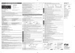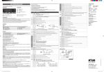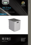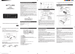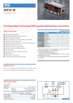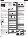
1
Thank you for having chosen an LAE electronic product. Before installing the instrument, please read this instruction booklet
carefully in order to ensure safe installation and optimum performance.
INDICATIONS
Defrost output
Activation of 2nd parameter set
Alarm
Fig.1 — Front panel
Info / Setpoint button.
Increase / manual activation button.
Manual defrost / Decrease button.
Exit / Stand-by button.
Insert the controller through a hole measuring 71x29 mm.
Make sure that electrical connections comply with the paragraph “wiring diagrams”. To reduce the effects of electromagnetic
disturbance, keep the sensor and signal cables well separate from the power wires.
Fix the controller to the panel by means of the suitable clips, by pressingly gently; if fitted, check that the rubber gasket
adheres to the panel perfectly, in order to prevent debris and moisture infiltration to the back of the instrument.
Place the probe T1 inside the room in a point that truly represents the temperature of the stored product.
Place the probe T2 on the evaporator where there is the maximum formation of frost.
The function of probe T3 is determined by the parameter T3. With T3=DSP the probe measures the temperature to be
displayed. With T3=CND the probe measures the condenser temperature, it must therefore be placed between the fins of the
condensing unit. With T3=2EU the probe measures the temperature of the second evaporator and it must therefore be placed
where there is the maximum formation of frost. With T3=NON, the third probe is disabled.
ON
OFF
DLI
To get access to the parameter configuration menu, press button X + for 5 seconds.
With button or select the parameter to be modified.
Press button to display the value.
By keeping button pressed, use button or
to set the desired value.
When button is released, the newly programmed value is stored and the following parameter is displayed.
To exit from the setup, press button X or wait for 30 seconds.
PAR
RANGE
SCL
1°C;
2°C;
°F
SP-ALR
During normal operation, the display shows either the temperature measured or one of the following indications:
HP
HI
LO
E1
E2
E3
Condenser high pressure alarm
Room high temperature alarm
Room low temperature alarm
Probe T1 failure
Probe T2 failure
Probe T3 failure
SPL
SPH
SP
C-H
HYS
Setpoint (value to be maintained in the room).
REF; HEA
Refrigerating (REF) or Heating (HEA) control mode
1...10°
INFO MENU
The information available in this menu is:
TLO Minimum probe 1 temperature recorded
CND Compressor working weeks
LOC Keypad state lock
Access to menu and information displayed.
Press and immediately release button .
With button or select the data to be displayed.
Press button to display value.
To exit from the menu, press button X or wait for 10 seconds.
Reset of THI, TLO, CND recordings
With button or select the data to be reset.
Display the value with button .
While keeping button pressed, use button X .
SETPOINT (display and modification of desired temperature value)
press button for at least half second, to display the setpoint value.
By keeping button pressed, use button or to set the desired value (adjustment is within the minimum SPL and the
maximum SPH limit).
When button is released, the new value is stored.
STAND-BY
Button , when pressed for 3 seconds, allows the controller to be put on a standby or output control to be resumed (with
SB=YES only).
Defrost termination. The actual defrost duration is influenced by a series of parameters.
Time termination: T2=NO and T3 different from 2EU: the evaporator temperature is not monitored and defrost will last as
long as time DTO.
OFF
T[°]
SP+HY
SP-HY
SP
T[°]
Compressor rest time. The output is switched on again after CRT minutes have elapsed since the previous
switchover. We recommend to set CRT=03 with HYS<2.0°.
CT1
CT2
0...30min
Thermostat output run when probe T1 is faulty. With CT1=0 the output will always remain OFF.
0...30min
Thermostat output stop when probe T1 is faulty. With CT2=0 and CT1>0 the output will always be ON.
Example: CT1=4, CT2= 6: In case of probe T1 failure, the compressor will cycle 4 minutes ON and 6 minutes OFF.
0..30min
Compressor stop delay after the door has been opened (active only if DS=YES).
0...120sec
Auxiliary compressor start delay. If OAU = 2CU the auxiliary output is switched on with a delay of 2CD seconds after
the main compressor has cut-in. Both compressors are turned off at the same time.
DFM
NON;
TIM;
FRO
Defrost start mode
NON : defrost function is disabled (the following parameter will be FID).
TIM : the defrost time count is increased continously.
FRO : the defrost time count is only increased when the conditions occur for frost to form on the evaporator
(optimised time increase).
DFT
DFB
0...99 hours
CSD
2CD
FID
FDD
FTO
FTC
NO/YES
-50...120°
1...120min
OFF;
ELE;
GAS
Time interval among defrosts. When this time has elapsed since the last defrost, a new defrost cycle is started.
Defrost timer count backup. With DFB=YES, after a power interruption, the timer resumes the count from where it
was left off with ±30 min. approximation. With DFB=NO, after a power interruption, the defrost timer will re-start
to count from zero.
Defrost end temperature.
Maximum defrost duration.
Pause after defrost (evaporator drain down time).
0...60min
Display during defrost. If DDY=0 during defrost the temperature continues to be displayed. If DDY > 0, during defrost
the display shows DEF, when defrost is over REC is displayed during DDY minutes.
NO/YES
Fans active during defrost.
-50...120°
Evaporator fan re-start temperature after defrost.
0...120min
Maximum evaporator fan stop after defrost.
NO/YES
Temperature alarm with relative thresholds,
heating control (ATM=REL, CH=HEA).
Compressor
Evap. fans
Defrost
Auxiliary loads
12(5)A 240Vac
7(2)A 240Vac
7(2)A 240Vac
7(2)A 240Vac
Inputs
Low temperature alarm differential. With ALR=0 the low temperature alarm is excluded.
Measurement Range
0... 12°
High temperature alarm differential. With AHR=0 the high temperature alarm is excluded.
-50…120°C, -55…240°F
-50 / -9.9 … 19.9 / 80°C (NTC10K only)
T1; T2; T3
Probe used for temperature alarm detection.
0... 120min
Delay before alarm temperature warning.
0... 30min
Delay before door open alarm warning.
NON;
ALR;
STP;
<0.5°C within the measurement range
Operating conditions
-10 … +50°C;
EN60730-1; EN60730-2-9;
EN55022 (Class B);
EN50082-1
Condenser periodic cleaning. When the compressor operation time, expressed in weeks, matches the ACC value
programmed, “CL” flashes in the display. With ACC=0 the condenser cleaning warning is disabled.
Front protection
1...5
Controller sensitivity for the automatic switchover from Group 1 to Group 2 (1=minimum, 5=maximum)
IP55
NON;
MAN;
HDD;
DI2
Switchover mode to second parameter set
NON: inhibition to use the second parameter group (the following parameter will be SB).
MAN: button M switches the two parameter groups over.
HDD: automatic switchover to the second parameter group, when heavy duty conditions are detected.
DI2: switchover to the second parameter group when the auxiliary DI2 input makes.
-50...IISH
Minimum limit for IISP setting.
Maximum limit for IISP setting.
IISL... IISH
15%...80% r.H.
CE (Reference Norms)
Condensation temperature alarm.
IISL...120°
LAE part No. SN4...
LAE part No. ST1…
Measurement accuracy
Operation in case of high condenser alarm
NON : high condenser alarm inhibited.
ALR : in case of alarm, “HC” flashes in the display and the buzzer is switched on.
STP : in addition to the alarm symbols displayed, the compressor is stopped and defrosts are suspended.
0...52
weeks
Setpoint in mode 2.
1...10°
OFF/ON differential in mode 2.
NO/YES
Optimised fan control enabling in mode 2.
0...99 hours
Defrost timer set to start a defrost in mode 2.
NO/YES
Stand-by button enabling
NO/YES
Door switch input enabling (closed when door is closed).
.
NON;
HPS;
IISM;
RDS
DI2 digital input operation
NON : digital input 2 not active.
HPS: when contact opens a condensing unit high pressure alarm occurs.
IISM : when contact makes the controller will use group 2 parameters.
RDS : when contact makes a defrost is started (remote control).
LSM
NON;
MAN;
DOR
Light control mode
NON : light output not controlled.
MAN : light ouput controlled through button M (if OAU=LGT).
DOR : light ouput switched on when door is opened (if OAU=LGT).
OAU
NON;
0-1;
LGT;
2CU;
2EU;
AL0;
AL1
AUX output operation
NON : output disabled (always off).
0-1 : the relay contacts follow the on/standby state of controller.
LGT : output enabled for light control.
2CU : output programmed for the control of an auxiliary compressor.
2EU : output enabled for the control of the electrical defrost of a second evaporator.
AL0 : contacts open when an alarm condition occurs.
AL1 : contacts make when an alarm condition occurs.
INP
SN4; ST1
OS1
T2
OS2
T3
-12.5..12.5°C
OS3
-12.5..12.5°C
TLD
SIM
ADR
1...30 min
Temperature sensor selection. With INP = SN4, the probes must be the LAE models SN4..; with INP = ST1, the probes
must be the LAE models ST1...
Probe T1 offset.
NO/YES
Probe T2 enabling (evaporator).
-12.5..12.5°C
Probe T2 offset.
NON;
DSP;
CND;
2EU
Defrost type
OFF: off cycle defrost (Compressor and Heater OFF).
ELE: electric defrost (Compressor OFF and Heater ON).
GAS: hot gas defrost (Compressor and Heater ON).
0...30min
SP+AHR
-12... 0°
Heating control (C-H=HEA)
0...30min
DRN
DDY
Defrost type. Once defrost has started, Compressor and Defrost outputs are controlled according to parameter DTY. If
FID=YES, the evaporator fans are active during defrost.
OFF
CRT
SELECTION OF SECOND PARAMETER GROUP
It’s possible to select control parameters between two different pre-programmed groups, in order for the fundamental control
parameters to be adapted quickly to changing needs.
Changeover from Group I to Group II may take place manually by pressing button M for 2 seconds (with IISM=MAN),
or automatically when heavy duty conditions are detected (with IISM=HDD), or when the auxiliary input DI2 is activated
(IISM=DI2). The activation of Group II is signalled by the lighting up of the relevant LED on the controller display. If IISM=NON,
switchover to group II is inhibited.
for 2 seconds, or defrost may
ON
Refrigerating control (C-H=REF )
DLI
DTO
DTY
Manual or remote defrost start. It’s possible to manually start a defrost, by pressing button
be started remotely, if DI2=RDS, through the making of the auxiliary contact DI2.
ON
SP
KEYPAD LOCK
The keypad lock avoids undesired, potentially dangerous operations, which might be attempted when the controllers is
operating in a public place. In the INFO menu, set parameter LOC=YES to inhibit all functions of the buttons. To resume normal
operation of keypad, adjust setting so that LOC=NO.
DEFROST
Automatic defrost. A defrost is started automatically as soon as the time set with parameter DFT has elapsed.
Timed defrost. With DFM=TIM the timer increment is continuous and defrosts take place at regular intervals. For example,
with DFM=TIM and DFT=06, a defrost will take place every 6 hours.
Optimised defrost. With DFM=FRO the timer is only increased when the conditions occur for frost to form on the evaporator,
until the time set with parameter DFT is matched. If the evaporator works at 0°C, defrost frequency depends on the thermal load
and climatic conditions. With setpoints much lower than 0°C, defrost frequency mainly depends on the refrigerator operating
time.
Defrost time count backup. At the power-up, if DFB=YES, the defrost timer resumes the time count from where it was left
off before the power interruption. Vice versa, with DFB=NO, the time count re-starts from 0. In stand-by, the accumulated time
count is frozen.
OFF/ON thermostat differential
IISL
IISH
IISP
IIHY
IIFT
IIDF
SB
DS
DI2
SP
NTC 10KΩ@25°C,
PTC 1000Ω@25°C,
HDS
IISM
SPL... SPH
SP-HYS-ALR
High temperature alarm threshold.
Readout scale.
1°C (with INP=SN4 only): measuring range -50/-9.9 … 19.9/80°C
2°C : measuring range -50 … 120°C
°F : measuring range -55 … 240°F
Minimum limit for SP setting
SP+HYS+AHR
-50... 120°
DESCRIPTION
Maximum limit for SP setting
Relay outputs
T[°]
Low temperature alarm threshold.
-50...120°
-50..SPH
SP
12Vdc ±10%, 3W
110 - 230Vac±10%, 50/60Hz, 3W
-50... 120°
AHT
ACC
SPL.120°
AD-3…D
AD-3...W
OFF
Temperature alarm with relative thresholds,
refrigerating control (ATM=REL, CH=REF).
Caution: upon changing the SCL value, it is then absolutely necessary to reconfigure the parameters relevant to the
absolute and relative temperatures (SPL, SPH, SP, ALA, AHA, etc..)
DISPLAY
T[°]
OFF
ALA
AHA
ALR
AHR
ATI
ATD
ADO
AHM
Power supply
ON
DEF1
Resuming thermostatic cycle. When defrost is over, if DRN is
ON
greater than 0, all outputs will remain off for DRN minutes, in order for
OFF
DEF2
the ice to melt completely and the resulting water to drain. Moreover, if
START
DRN
probe T2 is active (T2=YES), the fans will re-start when the evaporator
gets to a temperature lower than FDD; Vice versa, if probe T2 is not
active (T2=NO) or after defrost has come to an end, such condition does not occur by end of the time FTO, after FTO minutes
have elapsed the fans will be switched on anyway.
Caution: if DFM=NON or C-H=HEA all defrost functions are inhibited; if DFT=0, automatic defrost functions are excluded. During
a high pressure alarm, defrost is suspended. During defrost, high temperature alarm is bypassed.
OPERATION
ISTR AD3-5 INGLESE/ITALIANO.indd1 1
ON
CONFIGURATION PARAMETERS
INSTALLATION
T1 Instant probe 1 temperature
T2 Instant probe 2 temperature
T3 Instant probe 3 temperature
THI Maximum probe 1 temperature recorded
EVP1
Auxiliary probe T3 operation
NON: probe T3 not fitted.
DSP: temperature T3 to be displayed.
CND: condenser temperature measurement.
2EU: second evaporator temperature measurement.
Probe 3 offset.
Delay for minimum temperature (TLO) and maximum temperature (THI) logging.
0...100
Display slowdown.
1...255
AD3-5 address for PC communication.
WIRING DIAGRAMS
Optimised fan control enabling. With FTC = NO the fans remain on all the time.
CMP ON
CMP OFF
CMP ON
Aux
Switch
12...24Vac
RS485
ON
Door
Switch
Door
Switch
Aux
Switch
RS485
AUX
AUX
OFF
FT1
FT2
FT3
FT2
17 18
DI2
FT3
19
21
20
T1
FT1
FT2
FT3
Fan stop delay after compressor stop. See Fig. 2
0...30min
Timed fan stop. With FT2=0 the fans remain on all the time.
0...30min
Timed fan run. With FT3=0, and FT2 > 0, the fans remain off all the time.
22
T2
17 18
DI2
24
T3
19
21
20
T1
12(5)A 7(2)A 7(2)A
5
115...230Vac
6
23
22
24
T3
T2
AUX
AUX
Fig.2 Optimised fan control (FTC=YES)
0...180sec
23
12(5)A 7(2)A 7(2)A
7(2)A
7(2)A
12A
Fan output
Defrost in progress
Recovery after defrost
Controller in stand-by
Condenser clean warning
Door open alarm
Condenser high temperature alarm
DLI
TECHNICAL DATA
Alarm threshold management.
NON: all temperature alarms are inhibited (the following parameter will be ADO).
ABS: the values programmed in ALA and AHA represent the real alarm thresholds.
REL: the values programmed in ALR and AHR are alarm differentials referred to SP and SP+HY.
EVP2
Thermostat output
DEF
REC
OFF
CL
DO
HC
NON;
ABS;
REL
ATM
ON
OFF
12A
DESCRIPTION
Temperature monitoring of one evaporator: T2=YES and T3 different
from 2EU. In this case, if the sensor T2 measures the temperature DLI
before the time DTO elapses, defrost will be terminated in advance.
Temperature monitoring of two evaporators: T2=YES, T3=2EU,
OAU=2EU. This function is for the control of two independent
evaporators and it switches off the individual heating of the evaporator
which gets to temperature DLI first, waiting for the second evaporator
to get to that temperature before the time DTO elapses (see figure).
3
4
2
1
7
8
AD3-5C24W-BG
5
115...230Vac
6
3
4
2
1
7
8
AD3-5C14W-BG
VIA PADOVA, 25
31046 ODERZO /TV /ITALY
TEL. +39 - 0422 815320
FAX +39 - 0422 814073
www.lae-electronic.com
E-mail: [email protected]
PARTNER VENEZIA • 041 5460713
AD3-5 INSTRUCTIONS FOR USE
13-12-2007 9:53:58
INDICAZIONI
Uscita termostatazione
Uscita ventole
Uscita sbrinamento
Attivazione 2° set di parametri
Allarme
Fig.1 — Pannello frontale
Tasto Info / Setpoint.
Tasto incremento / modalità manuale.
Tasto sbrinamento manuale / decremento.
Tasto uscita / Stand-by.
PARAMETRI DI CONFIGURAZIONE
INSTALLAZIONE
Inserire lo strumento in un foro di dimensioni 71x29 mm;
Eseguire i collegamenti elettrici facendo riferimento al paragrafo “schemi di collegamento”. Per ridurre gli effetti delle
perturbazioni elettromagnetiche, distanziare i cavi delle sonde e di segnale dai conduttori di potenza.
Fissare lo strumento al pannello mediante le apposite staffette, esercitando una corretta pressione; qualora presente, la
guarnizione di gomma dev’essere interposta fra la cornice dello strumento ed il pannello, verificandone la perfetta adesione
per evitare infiltrazioni verso la parte posteriore dello strumento.
Posizionare la sonda T1 in un punto della cella che ben rappresenti la temperatura del prodotto da conservare.
Posizionare la sonda T2 sull’evaporatore nel punto di maggior formazione di brina.
La funzione della sonda T3 è determinata dal parametro T3. Con T3=DSP la sonda misura la temperatura da visualizzare sul
display; con T3=CND la sonda rileva la temperatura del condensatore, va quindi posizionata fra le alette dell’unità condensante;
con T3=2EU la sonda misura la temperatura del secondo evaporatore e va posizionata nel punto di maggior formazione di
brina; con T3=NON si disabilita l’utilizzo della terza sonda.
Per accedere al menù di configurazione dei parametri, premere per 5 secondi i tasti X + .
Con i tasti o selezionare il parametro da modificare.
Premere il tasto per visualizzare il valore.
Mantenendo premuto agire con i tasti
o
per impostare il valore desiderato.
Al rilascio del tasto il nuovo valore viene memorizzato e viene visualizzato il parametro successivo.
Per uscire dal setup premere il tasto X o attendere 30 secondi.
PAR
RANGE
SCL
1°C;
2°C;
°F
FUNZIONAMENTO
In funzionamento normale sul display viene visualizzata la temperatura rilevata oppure una delle indicazioni seguenti:
DEF sbrinamento in corso
REC ristabilimento dopo uno sbrinamento
OFF strumento in stand-by
CL richiesta pulizia condensatore
DO allarme porta aperta
HC allarme alta temperatura sul condensatore
HP
HI
LO
E1
E2
E3
allarme di alta pressione sul condensatore
allarme di alta temperatura in cella
allarme di bassa temperatura in cella
guasto nella sonda T1
guasto nella sonda T2
guasto nella sonda T3
SPL
SPH
SP
scala di lettura.
1°C (solo con INP=SN4): range di misura -50/-9.9 … 19.9/80°C
2°C : range di misura -50 … 120°C
°F : range di misura -55 … 240°F
HDS
IISM
C-H
HYS
-50..SPH
Limite minimo per la regolazione di SP.
Limite massimo per la regolazione di SP.
SPL... SPH
Temperatura di commutazione (valore che si desidera mantenere nella cella).
REF; HEA
Modo di regolazione refrigerazione (REF) o riscaldamento (HEA).
1...10°
Differenziale OFF/ON del termostato
ON
ON
Le informazioni disponibili nel menù info sono:
temperatura istantanea sonda 1
temperatura istantanea sonda 2
temperatura istantanea sonda 3
temp. massima registrata sonda 1
OFF
TLO temperatura minima registrata sonda 1
CND settimane di funzionamento del compressore
LOC stato della tastiera (blocco)
Accesso al menù e visualizzazione informazioni.
Premere e subito rilasciare il tasto .
Con i tasti o selezionare il dato da visualizzare.
Premere il tasto
per visualizzare il valore.
Per uscire dal menù, premere il tasto X o attendere 10 secondi.
Reset delle memorizzazioni THI, TLO, CND
Con i tasti o selezionare il dato da resettare.
Visualizzare il valore con il tasto .
Mantenendo premuto il tasto premere il tasto X .
SETPOINT (visualizzazione e modifica valore di temperatura desiderato)
Premere per almeno mezzo secondo il tasto per visualizzare il valore del setpoint.
Mantenendo premuto agire con i tasti o per impostare il valore desiderato (la regolazione è compresa entro il limite
minimo SPL e massimo SPH).
Al rilascio del tasto il nuovo valore viene memorizzato.
STAND-BY
Il tasto , premuto per 3 secondi, consente di commutare lo stato del regolatore fra operatività delle uscite e standby (solo
con SB=YES).
BLOCCO DELLA TASTIERA
Il blocco dei tasti impedisce operazioni indesiderate, potenzialmente dannose, che possono avvenire qualora il regolatore operi
in ambiente pubblico. Per inibire tutti i comandi da tastiera impostare LOC=YES nel menù INFO; per ripristinare la normale
funzionalità riprogrammare LOC=NO.
SELEZIONE SECONDO GRUPPO DI PARAMETRI
È possibile selezionare i parametri di regolazione fra due diversi gruppi pre-programmati, per adattare in pochi istanti i
parametri fondamentali del regolatore alle diverse esigenze. Il passaggio dal Gruppo I al Gruppo II può avvenire manualmente
premendo per 2 secondi il tasto M con IISM=MAN, automaticamente al rilevamento di condizioni di utilizzo particolarmente
severe con IISM=HDD, alla chiusura dell’ingresso ausiliario DI2 con IISM=DI2. L’attivazione del Gruppo II viene segnalata
dall’accensione dell’apposito LED sul regolatore. Se IISM=NON il passaggio al gruppo II è interdetto.
SBRINAMENTO
Sbrinamento automatico. Uno sbrinamento viene attivato automaticamente quando il timer interno raggiunge il tempo
impostato nel parametro DFT.
Sbrinamento temporizzato: Con DFM=TIM l’incremento del timer è continuo e gli sbrinamenti avvengono ad intervalli
regolari. Ad esempio con DFM=TIM e DFT=06 si avranno cicli di sbrinamento ad una distanza di 6 ore l’uno dall’altro.
Sbrinamento ottimizzato: Con DFM=FRO il timer viene incrementato solo al verificarsi delle condizione per la formazione di
brina sull’evaporatore, fino ad eguagliare il parametro DFT. Se l’evaporatore lavora attorno a 0°C la frequenza degli sbrinamenti
risulta funzione del carico termico e delle condizioni climatiche. Con setpoint molto inferiori a 0°C, la frequenza degli sbrinamenti
dipende principalmente dai tempi di funzionamento del refrigeratore.
Salvataggio conteggio: All’accensione dello strumento se DFB=YES il timer di sbrinamento riprende il conteggio dal tempo
accumulato prima dello spegnimento, altrimenti (DFB=NO) riparte da 0. In modalità stand-by il conteggio accumulato è
bloccato.
Sbrinamento manuale o remoto. È possibile attivare uno sbrinamento manualmente, premendo per 2 secondi il tasto ,
oppure, con DI2=RDS, tramite la chiusura del contatto ausiliario DI2.
Tipo di sbrinamento. Iniziato uno sbrinamento, le uscite Compressore e Sbrinamento sono comandate in conformità al
parametro DTY. Se FID=YES le ventole evaporatore sono attive durante uno sbrinamento.
Termine dello sbrinamento. La durata effettiva dello sbrinamento è influenzata da una serie di parametri.
Terminazione a tempo: T2=NO e T3 diverso da 2EU: la temperatura dell’evaporatore non viene monitorata e lo sbrinamento
avrà sempre durata pari al tempo DTO.
Monitoraggio temperatura su un evaporatore: T2=YES e T3 diverso da 2EU: qualora la sonda T2 raggiunga la temperatura DLI
ISTR AD3-5 INGLESE/ITALIANO.indd2 2
OFF
SP
T[°]
SP+HY
SP-HY
Regolazione in refrigerazione (C-H=REF )
SP
T[°]
Regolazione in riscaldamento (C-H=HEA)
CRT
0...30min
Tempo di fermata del compressore. La riaccensione dell’uscita avviene solo se sono trascorsi CRT minuti dal
precedente spegnimento. Consigliamo CRT=03 con HYS<2.0°.
CT1
CT2
0...30min
Tempo di attivazione dell’uscita termostato durante un’anomalia della sonda T1. Con CT1=0 l’uscita sarà sempre OFF.
0...30min
Tempo di fermata dell’uscita termostato durante un’anomalia della sonda T1. Con CT2=0 e CT1>0 l’uscita sarà sempre ON.
Esempio: CT1=4, CT2= 6: In caso di rottura della sonda T1 il compressore funziona con cicli di 4 minuti ON e 6 minuti OFF .
CSD
2CD
DFM
DFT
DFB
DLI
DTO
DTY
DRN
DDY
FID
FDD
FTO
FTC
0..30min
Ritardo della fermata del compressore in seguito all’apertura della porta (attivo solo se DS = YES).
0...120sec
Ritardo accensione compressore ausiliario. Se OAU=2CU l’uscita ausiliaria si attiva 2CD secondi dopo che il
compressore principale è entrato in funzione. Lo spegnimento rimane sempre simultaneo.
NON;
TIM;
FRO
Modalità di avvio di un ciclo di sbrinamento
NON : la funzione di sbrinamento viene disabilitata (il successivo parametro sarà FID).
TIM : il timer per l’attivazione dello sbrinamento è incrementato in modo continuo.
FRO : il timer viene incrementato solo quando sull’evaporatore si verificano le condizioni per la formazione di brina
(incremento ottimizzato).
0...99 ore
Valore del timer raggiunto il quale si ha l’avvio di un ciclo di sbrinamento.
NO/YES
Memorizzazione del tempo accumulato dal timer di sbrinamento. Con DFB=YES, dopo un’interruzione
dell’alimentazione (blackout) il timer riparte dal valore raggiunto al momento dello spegnimento ± 30 min. Con
DFB=NO, dopo un’interruzione dell’alimentazione, il timer riparte da zero.
-50...120°
Temperatura di fine sbrinamento.
1...120min
Durata massima dello sbrinamento.
OFF;
ELE;
GAS
Tipo di sbrinamento
OFF: sbrinamento a fermata (Compressore e Sbrinatore OFF).
ELE: sbrinamento elettrico (Compressore OFF e Sbrinatore ON).
GAS: sbrinamento a gas caldo (Compressore e Sbrinatore ON).
0...30min
Pausa dopo uno sbrinamento (sgocciolamento dell’evaporatore).
0...60min
Display in sbrinamento. Se DDY=0 durante uno sbrinamento continua ad essere visualizzata la temperatura. Se DDY > 0,
durante uno sbrinamento il display visualizza DEF, e al termine dello sbrinamento visualizza REC per DDY minuti.
NO/YES
Attivazione ventole in sbrinamento.
-50...120°
Temperatura di ripartenza ventole evaporatore dopo uno sbrinamento.
0...120min
Durata massima fermata ventole evaporatore dopo uno sbrinamento.
NO/YES
SP
-50... 120°
Soglia d’allarme di bassa temperatura.
-50... 120°
Soglia d’allarme di alta temperatura.
IISL
IISH
IISP
IIHY
IIFT
IIDF
SB
DS
DI2
T[°]
OFF
SP+HYS+AHR
SP-HYS-ALR
Allarme di temperatura con soglie relative,
controllo in refrigerazione (ATM=REL, C-H=REF).
AHT
ACC
SPL.120°
T[°]
SP-ALR
ALA
AHA
ALR
AHR
ATI
ATD
ADO
AHM
AD3-5
ON
OFF
DESCRIZIONE
MENU INFO
T1
T2
T3
THI
ON
SP
SP+AHR
Allarme di temperatura con soglie relative,
controllo in riscaldamento (ATM=REL, C-H=HEA).
-12... 0°
Differenziale d’allarme di bassa temperatura. Con ALR=0 l’allarme di bassa temperatura viene escluso.
0... 12°
Differenziale d’allarme di alta temperatura. Con AHR=0 l’allarme di alta temperatura viene escluso.
T1; T2; T3
Selezione sonda di riferimento per l’allarme di temperatura.
0... 120min
Ritardo nella segnalazione dell’allarme di temperatura.
0... 30min
Ritardo nella segnalazione dell’allarme di porta aperta.
NON;
ALR;
STP
Modo di funzionamento in caso di allarme del condensatore
NON : inibizione dell’allarme del condensatore.
ALR : in caso di allarme il display lampeggia “HC” e viene attivato il buzzer.
STP : oltre alle visualizzazioni d’allarme si ha l’immediata fermata del compressore e la sospensione degli sbrinamenti.
-50...120°
Temperatura d’allarme condensazione .
0...52
sett.
1...5
Sensibilità del regolatore per il passaggio automatico dal Gruppo 1 al Gruppo 2 (1=minimo, 5=massimo).
Modalità di passaggio al secondo set di parametri
NON: inibizione uso secondo gruppo di parametri (il successivo parametro sarà SB).
MAN: abilitazione tasto M per commutare i due gruppi di parametri.
HDD: passaggio automatico al secondo gruppo di parametri, al rilevamento di condizioni di utilizzo particolarmente severe.
DI2: passaggio al secondo gruppo di parametri alla chiusura dell’ingresso ausiliario DI2.
-50...IISH
Limite minimo per la regolazione di IISP.
IISL...120°
Limite massimo per la regolazione di IISP.
IISL... IISH
Setpoint in modalità 2.
1...10°
VIA PADOVA, 25
31046 ODERZO /TV /ITALY
TEL. +39 - 0422 815320
FAX +39 - 0422 814073
www.lae-electronic.com
E-mail: [email protected]
Differenziale OFF/ON in modalità 2.
NO/YES
Abilitazione controllo ottimizzato ventole in modalità 2.
0...99 ore
Valore del contaore per l’avvio di un ciclo di sbrinamento in modalità 2.
NO/YES
Abilitazione tasto standby
NO/YES
Abilitazione sensore ingresso porta (chiuso con porta chiusa).
.
NON;
HPS;
IISM;
RDS
Funzionamento dell’ingresso digitale DI2
NON : ingresso digitale 2 non attivo.
HPS: all’apertura si genera un allarme di alta pressione nell’unità condensante.
IISM : alla chiusura del contatto il regolatore utilizza come riferimento i parametri del gruppo 2.
RDS : alla chiusura del contatto viene avviato uno sbrinamento (comando remoto).
LSM
NON;
MAN;
DOR
Modalità comando luci
NON : uscita luci non gestita.
MAN : uscita luci controllata tramite il tasto M (se OAU=LGT).
DOR : uscita luci attivata all’apertura della porta (se OAU=LGT).
OAU
NON;
0-1;
LGT;
2CU;
2EU;
AL0;
AL1
Funzionamento dell’uscita ausiliaria AUX
NON : uscita disabilitata (sempre spenta).
0-1 : i contatti del relè seguono lo stato on/standby del regolatore.
LGT : uscita abilitata al controllo delle luci.
2CU : uscita programmata per il comando di un compressore ausiliario.
2EU : uscita abilitata al controllo dello sbrinamento elettrico del secondo evaporatore.
AL0 : apertura dei contatti al presentarsi di una condizione d’allarme.
AL1 : chiusura dei contatti al presentarsi di una condizione d’allarme.
INP
SN4; ST1
OS1
T2
OS2
T3
-12.5..12.5°C
DATI TECNICI
Alimentazione
AD-3…D
AD-3...W
Selezione del sensore di temperatura. Con INP = SN4 le sonde devono corrispondere ai modelli LAE SN4..; con
INP = ST1 devono corrispondere ai modelli LAE ST1...
NO/YES
-12.5..12.5°C
Ingressi
NTC 10KΩ@25°C, codice LAE SN4...
PTC 1000Ω@25°C, codice LAE ST1…
Range di misura
Utilizzo della sonda ausiliaria T3.
NON: sonda T3 non presente.
DSP: visualizzazione della temperatura T3 sul display.
CND: misurazione della temperatura del condensatore.
2EU: misurazione della temperatura del secondo evaporatore.
-50…120°C, -55…240°F
-50 / -9.9 … 19.9 / 80°C (solo NTC10K)
Precisione di misura
<0.5°C nel range di misura
OS3
-12.5..12.5°C
Correzione misura sonda 3.
TLD
SIM
ADR
1...30 min
Ritardo nella memorizzazione delle temperature minime (TLO) e massime (THI) raggiunte.
-10 … +50°C; 15…80% U.R.
0...100
Rallentamento display.
CE (Normative di riferimento)
1...255
Indirizzo di AD3-5 per la comunicazione con PC.
EN60730-1; EN60730-2-9;
EN55022 (Classe B);
EN50082-1
Condizioni operative
Protezione frontale
CMP ON
Interr.
Aux
12...24Vac
RS485
ON
12(5)A 240Vac
7(2)A 240Vac
7(2)A 240Vac
7(2)A 240Vac
Abilitazione della sonda T2 (evaporatore).
SCHEMI DI COLLEGAMENTO
CMP OFF
Compressore
Ventole evp
Sbrinamento
Carichi ausiliari
Correzione misura sonda T1.
Correzione misura sonda T2.
NON;
DSP;
CND;
2EU
12Vdc ±10%, 3W
110 / 230Vac±10%, 50/60Hz, 3W
Uscite relè
Abilitazione controllo ottimizzato ventole. Con FTC = NO le ventole rimangono sempre accese.
CMP ON
INSTRUCTIONS FOR USE
ISTRUZIONI D’USO
Pulizia periodica condensatore. Quando il tempo di funzionamento del compressore, espresso in settimane,
raggiunge il valore ACC, sul display lampeggia “CL”. Con ACC=0 l’indicazione per la pulizia del condensatore è
disabilitata.
NON;
MAN;
HDD;
DI2
Attenzione: cambiando il valore di SCL vanno assolutamente riconfigurati i parametri riguardanti le temperature
assolute e relative (SPL, SPH, SP, ALA, AHA, ecc..).
VISUALIZZAZIONI
Gestione soglie allarme.
NON: Tutti gli allarmi di temperatura sono interdetti. (Il successivo parametro sarà ADO)
ABS: I valori programmati in ALA e AHA rappresentano le reali soglie d’allarme
REL:I valori programmati in ALR e AHR sono i differenziali d’allarme rispetto a SP e SP+HY
Interr.
porta
IP55
Interr.
porta
Interr.
Aux
RS485
AUX
AUX
OFF
FT1
FT2
FT3
FT2
17 18
DI2
FT3
Fig. 2. Controllo ottimizzato ventole (FTC=YES).
FT1
FT2
FT3
0...180sec
Ritardo spegnimento ventole dopo lo spegnimento del compressore. Vedi Fig.2
0...30min
Fermata temporizzata ventole. Con FT2=0 le ventole rimangono sempre in funzione.
0...30min
Corsa temporizzata ventole. Con FT3=0 e FT2 > 0, le ventole rimangono sempre spente.
19
21
20
T1
23
22
T2
17 18
DI2
24
T3
19
21
20
T1
5
115...230Vac
6
23
22
24
T3
T2
AUX
AUX
12(5)A 7(2)A 7(2)A
12(5)A 7(2)A 7(2)A
7(2)A
12A
DESCRIZIONE
NON;
ABS;
REL
ATM
PARTNER VENEZIA • 041 5460713
Vi ringraziamo per la preferenza accordataci scegliendo un prodotto LAE electronic. Prima di procedere all’installazione dello
strumento, leggete attentamente il presente foglio d’istruzioni: solo così potrete ottenere massime prestazioni e sicurezza.
entro il tempo DTO, lo sbrinamento avrà una conclusione anticipata.
ON
Monitoraggio temperatura su due evaporatori: T2=YES, T3=2EU,
OFF
OAU=2EU: questa modalità è destinata al controllo indipendente di due
DLI
evaporatori e prevede lo spegnimento individuale del riscaldamento
EVP1
dell’evaporatore che raggiunge per primo la temperatura DLI in attesa
ON
che, entro il tempo DTO, anche il secondo raggiunga tale temperatura
OFF
(v. figura).
DEF1
DLI
Ristabilimento del ciclo termostatico. Terminato lo sbrinamento, se
EVP2
DRN è maggiore di 0, tutte le uscite rimarranno spente per DRN minuti,
ON
per consentire una completa fusione del ghiaccio e lo smaltimento
OFF
dell’acqua formatasi. Inoltre, qualora la sonda T2 sia attiva (T2=YES),
DEF2
le ventole ripartiranno quando l’evaporatore avrà una temperatura
START
DRN
inferiore a FDD; se però o la sonda T2 non è attiva (T2=NO) o, dopo la
conclusione dello sbrinamento, tale condizione non si verifica entro il
tempo FTO, trascorsi FTO minuti le ventole vengono comunque riavviate.
Attenzione: se DFM=NON o C-H=HEA tutte le funzioni di sbrinamento sono inibite; se DFT=0 vengono escluse le funzioni di
sbrinamento automatico; durante un allarme di Alta Pressione lo sbrinamento è sospeso; durante uno sbrinamento l’allarme
d’alta temperatura è sospeso.
7(2)A
AD3-5
7
INSTRUCTIONS FOR USE
EN
ISTRUZIONI D’USO
IT
12A
AD3-5 ISTRUZIONI D’USO
3
4
2
1
7
8
AD3-5C24W-BG
5
115...230Vac
6
3
4
2
1
8
AD3-5C14W-BG
0LAD3002-05
13-12-2007 9:54:07