1
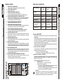
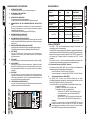
Digital Vertical Array
A.E.B. INDUSTRIALE s.r.l.
Via Brodolini, 8 - 40056 Crespellano (Bo) - ITALIA
Tel. + 39 051 969870 - Fax. + 39 051 969725
Internet: www.dbtechnologies.com
E-mail: [email protected]
MANUALE D’USO
USER MANUAL
BEDIENUNGSANLEITUNG
CARACTERISTIQUES TECHNIQUES
420120118 - Rev 2
1
ATTENZIONE:
"AVIS"
PER RIDURRE IL RISCHIO DI SCOSSA
RISQUE DE CHOC ELECTRIQUE
ELETTRICA, NON TOGLIERE IL
NE PAS OUVRIR
POUR PREVENIR TOUT RISQUE DE FEU
C O P E R C H I O ( O I L PA N N E L L O
REPLACER UN FUSIBLE
DE MÊME CARACTERISTIQUES
POSTERIORE). ALL’INTERNO NON SONO
CET APPAREIL DOIT ÊNTRE RELIÉ A LA TERRE
C O N T E N U T E PA R T I R I PA R A B I L I
DALL’UTENTE; AFFIDARE LE RIPARAZIONI
"CAUTION"
TO PREVENT ELECTRICAL SHOCK
A PERSONALE QUALIFICATO.
DO NOT REMOVE COVER
TO PREVENT RISK OF FIRE
PER RIDURRE IL RISCHIO DI INCENDIO O DI
REPLACE FUSES WITH
SAME TYPE AND RATINGS
SCOSSA ELETTRICA, NON ESPORRE
THIS APPARATUS MUST BE EARTHED
QUESTO APPARECCHIO ALLA PIOGGIA O
ALL’UMIDITÀ.
Questo simbolo, dove compare, ha lo scopo di avvisare l’utente di presenza di
tensione pericolosa all’interno del prodotto che può essere di portata sufficiente a
costituire un rischio di scossa elettrica per le persone.
Questo simbolo, dove appare, ha lo scopo di avvisare l’utente di presenza di
importanti istruzioni d’uso e manutenzione (assistenza) nella documentazione che
accompagna l’apparecchio.
ISTRUZIONI DI SICUREZZA NEL DETTAGLIO:
Leggere queste istruzioni
Tutte le istruzioni di sicurezza e di funzionamento devono essere lette prima di mettere in funzione
l'apparecchio.
Conservare queste istruzioni
Le istruzioni di sicurezza e di funzionamento devono essere conservate per ogni riferimento futuro.
Tenere conto di tutti gli avvertimenti
Tutte le avvertenze sull'apparecchio e le istruzioni di funzionamento devono essere seguite
fedelmente.
Seguire tutte le istruzioni
Tutte le istruzioni di funzionamento e per l'utente devono essere seguite.
Acqua e umidità
L'apparecchio non deve essere usato in prossimità di acqua (per esempio vicino a vasche da bagno,
lavabi, lavelli da cucina, vasche per il bucato, su pavimento bagnato oppure in prossimità di piscine….)
Pulizia
Pulire solo con un panno asciutto. Per la pulizia delle parti esterne evitare l’uso di diluenti, alcool,
benzina o altre sostanze volatili.
Ventilazione
Non ostruire alcuna delle aperture di ventilazione. Installare questo apparecchio in accordo con le
istruzioni fornite dal produttore. L’apparecchio deve essere posto in modo tale che la sua collocazione
o posizione non interferisca con l’adeguata ventilazione.
Calore
Non installare l'apparecchio in prossimita’ di fonti di calore come radiatori, stufe oppure altri apparecchi
(inclusi gli amplificatori) che producono calore.
Messa a terra
Non pregiudicare la polarizzazione o la messa a terra della spina. Per evitare il rischio di shock elettrici
le parti metalliche del diffusore devono essere connesse a terra. Una spina polarizzata ha due poli, di
cui uno più’ largo dell’altro. Una spina con la messa a terra ha due poli ed un terzo polo per la messa a
terra. Il polo più’ largo o il terzo polo sono forniti per la vostra sicurezza. Se la spina non si inserisce
nella vostra presa di rete, rivolgersi ad un elettricista per la sostituzione della presa obsoleta.
L’altoparlante dovrà essere collegato a una presa di alimentazione principale con il collegamento a
terra.
Alimentazione
L'apparecchio deve essere collegato solo al tipo di alimentazione descritto nelle istruzioni d'uso
oppure riportato sull'apparecchio stesso. Per non compromettere la sicurezza del diffusore,
quest’ultimo deve essere connesso alla rete di alimentazione solamente tramite il cavo di
alimentazione fornito a corredo.
L’interruttore principale posto sul retro (DPDT) è usato per sconnettere l’apparecchio.
Cavo di alimentazione
Proteggere il cavo d’alimentazione dalla possibilità’ di essere calpestato o pizzicato, in particolare in
prossimità’ della spina e nel punto in cui si inserisce nell’apparecchio.
Accessori
Utilizzare solo con accessori specificati dal produttore.
Periodi di non utilizzo
Staccare l’apparecchio dalla presa d’alimentazione nel caso di lampi o tuoni o nel caso di un lungo
periodo di non utilizzo.
Ingresso di liquidi e oggetti nell' apparecchio
Assicurarsi che oggetti non cadano sull’apparecchio o che non si versino liquidi attraverso le
aperture.
Danni che richiedono l'assistenza
Per qualunque riparazione rivolgersi a personale qualificato. Un intervento tecnico e’ richiesto
quando:
l’apparecchio e’ stato danneggiato;
il cavo di alimentazione o la presa siano danneggiati;
sono caduti oggetti sull’apparecchio o liquidi siano entrati all’interno
l'apparecchio è stato esposto alla pioggia o all’umidita’:
l'apparecchio non sembra funzionare normalmente oppure ha cambiato le sue prestazioni;
l'apparecchio è caduto.
Manutenzione
L'utente non deve tentare di riparare l'apparecchio al di là di quello descritto nelle istruzioni. Tutte le
altre riparazioni devono essere eseguite da personale qualificato.
IMPORTANTE
Il presente manuale costituisce parte integrante del prodotto e deve accompagnare quest’ultimo
anche nei passaggi di proprietà, per permettere al nuovo proprietario di conoscere le modalità
d’installazione e d’utilizzo e le avvertenze per la sicurezza.
L’installazione errata del diffusore esime la dB Technologies da ogni responsabilità.
Italiano
AVVERTENZA:
Carrelli e sostegni
Utilizzare solo carrelli, basamenti, treppiedi, staffe o sostegni consigliati dal produttore o forniti in
dotazione all’apparecchio. Quando viene utilizzato un carrello, usare cautela durante lo spostamento
dell’apparecchio per evitare infortuni a causa di capovolgimenti.
Manuale d’uso
Manuale d’uso
Italiano
IMPORTANTI ISTRUZIONI DI SICUREZZA
PRECAUZIONI PER L’UTILIZZO
Evitate di far lavorare l’amplificatore interno al diffusore in sovraccarico per lungo tempo.
Non usare la forza sugli organi di comando (tasti, controlli, ecc.).
ATTENZIONE
-
Collocate il diffusore in modo stabile e sicuro, così da evitare qualsiasi condizione di pericolo
per l’incolumità di persone o strutture.
COLLEGAMENTI
ATTENZIONE
-
-
Per il collegamento del diffusore si raccomanda di rivolgersi a personale qualificato ed
addestrato, ossia personale avente conoscenze tecniche o esperienza o istruzioni specifiche
sufficienti per permettergli di realizzare correttamente le connessioni e prevenire i pericoli
dell’elettricità.
Per evitare il rischio di shock elettrici, il diffusore deve essere alimentato dalla tensione di rete
solo dopo aver terminato tutti i collegamenti.
Prima di alimentare il diffusore è buona norma ricontrollare tutte le connessioni.
Tutto l’impianto di sonorizzazione dovrà essere realizzato in conformità con le norme e le leggi
vigenti in materia di impianti elettrici.
AVVERTENZA
-
Per evitare che fenomeni induttivi diano luogo a ronzii, disturbi e compromettano il buon
funzionamento del diffusore, i cavi che trasmettono segnali microfonici o segnali a livello linea
(es. 0 dB/V) devono essere schermati e non devono essere posti in prossimità di:
1)
apparecchiature che producono forti campi magnetici (es. grossi trasformatori di
alimentazione).
2)
conduttori dell’energia elettrica.
3)
linee che alimentano diffusori.
2
2)
3)
Manuale d’uso
4)
5)
6)
7)
8)
9)
10)
11)
12)
INTERRUTTORE ALIMENTAZIONE
L’interruttore permette l’accensione e lo spegnimento del diffusore.
PORTA FUSIBILE “MAINS FUSE”
Alloggio per fusibile di rete.
PRESA DI ALIMENTAZIONE “MAINS INPUT”
Consente la connessione del cavo di alimentazione.
Il connettore utilizzato per il collegamento alla rete è un POWER CON® (blu)
PRESA DI ALIMENTAZIONE RILANCIO “MAINS OUTPUT LINK”
Consente di rilanciare l’alimentazione di rete. L’uscita è connessa in parallelo con
l’ingresso (3) e può essere utilizzata per alimentare un altro diffusore amplificato.
Il connettore utilizzato è un POWER CON® (grigio).
CONNETTORE DI INGRESSO " BALANCED INPUT”
Connettore XLRIngresso bilanciato a livello linea .
CONNETTORE DI USCITA "BALANCED LINK/OUT”
Il connettore “XLR” connesso in parallelo con l’ingresso (5) può essere utilizzato per
inviare il segnale audio in ingresso ad un altro diffusore amplificato.
CONTROLLO SENSIBILITA’ INGRESSO “INPUT SENS”
Questo controllo regola la sensibilità del segnale in ingresso all’amplificatore.
Tale controllo non influisce sul livello dell’uscita “BALANCED LINK/OUT”
INDICATORE LUMINOSO “LIMITER”
Questo indicatore s’illumina di colore rosso per indicare l'intervento del circuito
limitatore interno, il quale evita la distorsione dell'amplificatore e protegge gli
altoparlanti contro sovraccarichi.
INDICATORE LUMINOSO “SIGNAL”
Questo indicatore s'illumina di colore verde per indicare la presenza del segnale
audio (ad un livello di -20dB).
INDICATORE LUMINOSO “MUTE/PROT”
Questo indicatore di colore giallo indica lo stato dell’amplificatore. Nel normale
funzionamento il led è spento; nel caso in cui lampeggi o sia sempre acceso fare
riferimento alla tabella della diagnostica per la verifica dello stato dell’amplificatore.
INDICATORE LUMINOSO “READY”
Questo indicatore s'illumina di colore verde per indicare che la tensione di
alimentazione di rete è corretta. Nel normale funzionamento il led è acceso; nel
caso in cui lampeggi o sia spento fare riferimento alla tabella della diagnostica per la
verifica dello stato dell’amplificatore.
SELETTORE SETTAGGIO EQUALIZZAZIONE “SET-UP MODE”
Questo commutatore rotativo a 10 posizioni permette di selezionare la curva di
equalizzazione più adeguata al tipo di installazione.
Consultare la tabella per la corrispondenza delle curva di equalizzazione.
5
WARNING
HOT SURFACE
BALANCED
INPUT
dB
Digital Vertical Array
BALANCED
LINK / OUT
7
ACTIVE P.F.C.
4
MAINS
LINK
"CAUTION"
+10dB
3
3
TO PREVENT ELECTRICAL SHOCK
DO NOT REMOVE COVER
TO PREVENT RISK OF FIRE
REPLACE FUSES WITH
SAME TYPE AND RATINGS
THIS APPARATUS MUST BE EARTHED
INPUT SENS
8
9
10
11
FULL RANGE MAINS INPUT
50-60Hz
85-265V
500W MAX
TECHNOLOGIES
T4
PUSH
6
1 = GND
2 = HOT
3 = COLD
"AVIS"
RISQUE DE CHOC ELECTRIQUE
NE PAS OUVRIR
POUR PREVENIR TOUT RISQUE DE FEU
REPLACER UN FUSIBLE
DE MÊME CARACTERISTIQUES
CET APPAREIL DOIT ÊNTRE RELIÉ A LA TERRE
+4dB
0dB
LIMITER
SIGNAL
SERIAL N.
READY
9
SET-UP
MODE
0
1
2
8
7
3
6
5
4
WARNING
HOT SURFACE
12
MAINS
FUSE
85-125V (T4A 250V)
200-250V (T2A 250V)
ON
MUTE/PROT
2
1
STATO DEL MODULO
LED ”READY”
(verde)
LED “MUTE/PROT” FUNZIONI
AUDIO
(giallo)
Accensione
Spento
Acceso per 5 sec.
Uso normale
Modifica equalizzazione
Acceso
Spento
Spento
Acceso per 5 sec.
Anomalia parziale
Anomalia totale
Temperatura amplificatore:
superiore 70°C
Acceso
Acceso
Lampeggio lento
Lampeggio lento
Acceso
Lampeggio lento
Acceso
Lampeggio veloce
superiore 80°C
Caricamento dati
In mute per 5 sec.
Complete
Caricamento dati
In mute per 5 sec.
Parziale
In mute
Riduzione volume
in uscita a step
Riduzione volume
in uscita -15dB
Funzione “NOISE GATE”
Il NOISE GATE, o soppressore di rumore di fondo, riduce il soffio del diffusore in assenza
di segnale audio.
Il NOISE GATE interviene dopo qualche secondo di assenza di segnale audio , mettendo
in stato di MUTE l’amplificatore. Lo stato di MUTE è segnalato da un lampeggio veloce,
con cadenza lenta, del led giallo “MUTE/PROT”. Alla rilevazione del segnale audio, il
diffusore uscirà dallo stato di “MUTE” automaticamente.
Questa opzione può essere abilitata o disabilitata a seconda delle esigenze, mediante una
procedura da eseguire sul modulo amplificatore .
Manuale d’uso
Italiano
1)
Italiano
TABELLA DELLA DIAGNOSTICA
COMANDI E FUNZIONI
1) Verificare stato funzione “NOISE GATE”
Lo stato della funzione “ NOISE GATE” viene visualizzata dai led presenti sul pannello
amplififcatore durante l’accensione del modulo.
Funzione attiva = tutti i led accesi per 5-6 secondi
Funzione disattiva = solo il led giallo “MUTE/PROT” acceso per 5-6 secondi
2) Abilitazione/disabilitazione NOISE GATE
L’abilitazione e la disabilitazione del NOISE GATE avviene in maniera sequenziale ad ogni
spegnimento/accensione dell'amplificatore solo con selettore “SET-UP MODE” nella
posizione “9 “(service use only)
Per abilitare/disabilitare il NOISE GATE seguire la procedura:
Amplificatore spento
Selezionare posizione "9" del selettore “SET-UP MODE”
Accendere il modulo e controllare che:
*
Se il led rosso “LIMITER" rimane acceso fisso per qualche secondo
significa che la funzione NOISE GATE è stata disabilitata
*
Se il led rosso "LIMITER" lampeggia velocemente per qualche secondo
significa che la funzione NOISE GATE è stata abilitata
Attenzione!
Dopo l’abilitazione o la disabilitazione della funzione NOISE GATE, spegnere
l'amplificatore, selezionare con il selettore “SET-UP MODE” una posizione
(equalizzazione) che non sia la posizione"9" e riaccendere il sistema.
4
Sensibilità ingresso nominale
Impedenza ingresso Bilanciato
Sbilanciato
Delay totale
Alimentazione
240
Forma diffusore
Dimensioni [LxHxP]
Peso
330
580
5
CAUTION:
WARNING:
TO REDUCE THE RISK OF ELECTRICAL
SHOCK, DO NOT REMOVE THECOVER
(OR BACK). NO USER SERVICEABLE
PARTS INSIDE; REFER SERVICING TO
QUALIFIED PERSONNEL.
TO REDUCE THE RISK OF FIRE OR
ELECTRICAL SHOCK. DO NOT EXPOSE
THIS APPLIANCE TO RAIN OR
MOISTURE.
"CAUTION"
TO PREVENT ELECTRICAL SHOCK
DO NOT REMOVE COVER
TO PREVENT RISK OF FIRE
REPLACE FUSES WITH
SAME TYPE AND RATINGS
THIS APPARATUS MUST BE EARTHED
"AVIS"
RISQUE DE CHOC ELECTRIQUE
NE PAS OUVRIR
POUR PREVENIR TOUT RISQUE DE FEU
REPLACER UN FUSIBLE
DE MÊME CARACTERISTIQUES
CET APPAREIL DOIT ÊNTRE RELIÉ A LA TERRE
This symbol, wherever it appears, alerts you to the presence of uninsulated
dangerous voltage voltage inside the enclosure - voltage that may be sufficient to
constitute a risk of shock.
This symbol wherever it appears, alerts you to important operating and
maintenance instructions in the accompanying literature. Read the manual.
DETAILED SAFETY INSTRUCTIONS:
Read these instructions:
All the safety and operation instructions should be read before the appliance is operated.
Keep these instructions:
The safety and operating instructions should be retained for future reference.
Heed all Warnings:
All warnings on the appliance and in the operating instructions should be adhered to
Follow all instructions:
All operation and user instructions should be followed
Water and Moisture:
Do not use this apparatus near water (e.g. near a bathtub, washbowl, kitchen sink, laundry tub, in a wet
basement, or near a swimming pool etc.)
Cleaning:
Clean only with a dry cloth. Do not use solvents, alcohol, benzene or volatile substances for cleaning
the exterior parts.
Ventilation
Do not block any of the ventilation openings. Install in accordance with the manufacturers instructions.
The appliance should be situated so that its location or position does not interfere with its proper
ventilation.
Heat:
Do not install the appliance near any heat sources such as radiators, heat registers, stoves, or other
appliance (including amplifiers) that produce heat.
Grounding or Polarization:
Do not defeat the safety purpose of the polarized or grounding/type plug. To prevent the risk of
electrical shock, the metallic parts of the speaker must be earthed. A polarized plug has two blades
with one wider than the other. A grounding type plug has two blades and a third grounding prong. The
wide blade or the third prong are provided for your safety. When the provided plug does not fit into your
outlet, consult an electrician for replacement of the obsolete outlet.
Speaker shall be connected to a MAINS socket outlet with a protective earthing connection.
Power Source
The appliance should be connected to a power supply only of the type described in the operating
instructions or as marked on the appliance. In order not to jeopardize the safety of the speaker, it must
only be connected to the mains using the power cable provided.
DPDT Mains Switch is used as the disconnect device located at the rear.
Power Cord Protection:
Protect the power cord from being walked on or pinched particularly at plugs, convenience
receptacles, and the point where they exit from the apparatus.
Accessories:
Only use attachments/accessories specified by the manufacturer.
Carts and stands:
Use only with a cart, stand, tripod, bracket, or table specified by the manufacturer, or sold with tha
apparatus. When a cart is used, use caution when moving the cart-apparatus combination to avoid
injury from tip-over.
user manual
Pressione sonora (SPL)
Componenti
Attivo 3-Amps
Digitale - Classe T
420 W
840 W
80-19.000Hz
420 - 2500Hz
24dB/oct
128 peak
1 woofer 8” - bobina 64mm - neodimio
1 midrange 6,5” - bobina 38mm - neodimio
2 compression driver da 1” - neodimio
0 dBu
20Kohm
10Kohm
1,2mS
full-range con PFC
85-265V~ 50-60Hz
trapezioidale
580x330x240/160mm
13,2Kg
160
Italiano
Manuale d’uso
Sistema
Tipologia amplificatore
Potenza RMS
Potenza musicale
Risposta in frequenza +/-3dB
Crossover
English
IMPORTANT SAFETY INSTRUCTIONS
DATI TECNICI
6
IMPORTANT NOTES
This manual is to be considered an integral part of the product, and must always accompany the
speaker when it changes ownership as a reference for correct installation and operation as well as for
the safety regulations.
dB Technologies will not assume any responsibility for incorrect installation of the speaker.
OPERATING PRECAUTIONS
Do not force the amplifier incorporated in the speaker to work in overload for extended periods
of time.
Never force the control elements (switches, controls, etc.).
CAUTION
-
Make sure that the speaker is positioned in a stable and secure way in order to avoid any
dangerous conditions for persons or objects.
1)
2)
3)
4)
5)
6)
7)
8)
9)
10)
CONNECTION
CAUTION
-
-
For connecting the speaker, use only qualified and experienced personnel having sufficient
technical knowledge or specific instructions for making the connections correctly and thus
preventing electrical dangers.
To prevent the risk of electrical shock, the speaker must only be supplied from the mains after all
connections have been completed.
Before powering up the speaker, it is advisable to re-check all the connections, making sure in
particular that there are no short circuits.
The entire sound system must be designed and installed in compliance with the current
standards and regulations regarding electrical systems.
CAUTION
-
12)
5
WARNING
HOT SURFACE
BALANCED
INPUT
6
dB
Digital Vertical Array
BALANCED
LINK / OUT
7
3
ACTIVE P.F.C.
4
MAINS
LINK
"CAUTION"
TO PREVENT ELECTRICAL SHOCK
DO NOT REMOVE COVER
TO PREVENT RISK OF FIRE
REPLACE FUSES WITH
SAME TYPE AND RATINGS
THIS APPARATUS MUST BE EARTHED
+10dB
INPUT SENS
8
9
10
11
FULL RANGE MAINS INPUT
50-60Hz
85-265V
500W MAX
TECHNOLOGIES
T4
1 = GND
2 = HOT
3 = COLD
PUSH
7
To prevent inductive phenomena from giving rise to hum or disturbance which would jeopardize
efficient
seaker operation, the cables that transmit microphone signals or line level signals
(e.g. 0 dB/V) must be screened and should not be run in the vicinity of:
1)
Equipment that produces strong magnetic fields (e.g. large power supply transformers)
2)
Electrical energy conductors
3)
Lines that supply speakers.
11)
POWER SWITCH
This switch permits turning the speaker on and off.
"MAINS FUSE" FUSE CARRIER
Mains fuse housing.
"MAINS INPUT" POWER SOCKET
For connecting the power cable provided.
The connector used for mains connection is a POWER CON® (blue)
“MAINS OUTPUT LINK” RELAUNCH POWER SOCKET
For relaunching the mains power. The output is connected in parallel with input (3)
and can be used to power another amplified speaker.
The connector uses a POWER CON® (grey)
" BALANCED INPUT” INPUT CONNECTOR
Balanced input at line level. It is able to accept “XLR” sockets.
"BALANCED LINK/OUT ” OUTPUT CONNECTOR
The “XLR” connector connected in parallel with input (5) can be used to send the
input audio signal to another amplified speaker.
“INPUT SENS” INPUT SENSITIVITY CONTROL
This control regulates the sensitivity of the signal amplifier input.
This control does not affect the “BALANCED LINK/OUT” output level
“LIMITER” INDICATOR LIGHT
This indicator comes on red to indicate that the internal limiter circuit has tripped.
This prevents amplifier distortion and protects the speakers against overloads.
“SIGNAL” INDICATOR LIGHT
This indicator comes on green to indicate the presence of the audio signal (at a level
of -20dB).
“MUTE/PROT” INDICATOR LIGHT
This yellow indicator indicates amplifier status. In normal operating conditions, the
LED is off; if it flashes or is always on, refer to the diagnostics table to check amplifier
status.
“READY” INDICATOR LIGHT
This indicator comes on green to indicate that the main power voltage is correct. In
normal operating conditions, the LED is on; if it flashes or is off, refer to the
diagnostics table to check amplifier status.
“SET-UP MODE” EQUALIZATION SWITCH
This 10-position rotating switch permits selection of the equalization curve according
to installation type.
See table for corresponding equalization curve.
"AVIS"
RISQUE DE CHOC ELECTRIQUE
NE PAS OUVRIR
POUR PREVENIR TOUT RISQUE DE FEU
REPLACER UN FUSIBLE
DE MÊME CARACTERISTIQUES
CET APPAREIL DOIT ÊNTRE RELIÉ A LA TERRE
+4dB
0dB
LIMITER
SIGNAL
SERIAL N.
READY
9
SET-UP
MODE
0
1
2
8
7
3
6
5
4
WARNING
HOT SURFACE
12
MAINS
FUSE
85-125V (T4A 250V)
200-250V (T2A 250V)
ON
MUTE/PROT
English
CONTROLS AND FUNCTIONS
user manual
English
user manual
Non-use Periods:
Unplug this apparatus during lightning storms or when unused for long periods of time.
Object and Liquid Entry
Care should be taken so that objects do not fall and liquids are not spilled into the enclosure through
openings.
Damage Requiring Service
Refer all servicing to qualified service personnel. Servicing is required when:
the apparatus has been damaged in any way;
the power supply cord or the plug has been damaged;
Objects have fallen, or liquid had been spilled into the appliance;
The appliance has been exposed to rain or moisture;
The appliance does not appear to operate normally or exhibits a marked change in
performance;
The appliance had been dropped.
Servicing:
The user should not attempt to service the appliance beyond that is described in the Operating
Instructions. All other servicing should be referred to qualified service personnel.
2
1
8
Power ON
Off
On for 5 sec.
Normal use
Equalization changing
On
Off
Off
On for 5 sec.
Teilweise fault
Total fault
Amplifier temperature:
higher 70°C
On
On
Slow flashing
Slow flashing
On
Slow flashing
On
Fast flashing
higher 80°C
Data loading
In mute for 5 sec.
Complete
Data loading
In mute for 5 sec.
teilweise
In mute
Output volume
Reduction step
Output volume
reduction -15dB
“NOISE GATE” function
NOISE GATE, or residual noise suppressor, is a function to reduce noise of the speaker
without input audio signal applied.
NOISE GATE starts to work when there is no audio signal on input, after a few seconds, it
sets the amplifier section in MUTE state . MUTE state is indicated by slow flashing, of
“MUTE/PROT” yellow led. As soon as the audio signal passes he input section, the
speaker is set out of MUTE status automatically.
This option can be enabled and disabled according to the follow procedure on the
amplifier’s module.
1) How to check NOISE GATE status
The NOISE GATE status is visualized by the leds located on the amplifier panel during
switching on the module.
Function enabled =all leds flashes steady for 5-6 second.
Function disabled = only “MUTE/PROT” yellow led flasches steady for 5-6 second
2)
NOISE GATE enabled/disabled
NOISE GATE enabled/disabled can be done each time when switching ON and OFF the
amplifier module with “SET-UP MODE” selector on position “9 “(service use only).
To enable/disable NOISE GATE function follow this procedure:
Amplifier switched OFF
Set “SET-UP MODE” selector in position "9"
Switch ON the amplifier module and check following:
* if “LIMITER" red led steady flashes for a few seconds, the NOISE
GATE is enabled.
* if “LIMITER" red led flashes fast for a few seconds, the NOISE
GATE is disabled
System
Type of amplifier
RMS power
Musical power
Frequency responce +/-3dB
Crossover
Active 3-Amps
Digital - Class T
420 W
840 W
80-19.000Hz
420 - 2500Hz
24dB/oct
128 peak
1 woofer 8” - coil 64mm - neodymium
1 midrange 6,5” - coil 38mm - neodymium
2 compression driver da 1” - neodymium
0 dBu
20Kohm
10Kohm
1,2mS
full-range with PFC
85-265V~ 50-60Hz
trapezioid
580x330x240/160mm
13,2Kg
Sound pressure (SPL)
Component parts
Input sensitivity nominal
Impedence Bilanced
Unbalanced
Delay totale
Power supply
Speaker shape
Dimension [LxHxP]
Weight
user manual
LED “MUTE/PROT” AUDIO
(yellow)
FUNCTIONS
580
330
LED ”READY”
(green)
160
MODULE STATUS
English
TECHNICAL SPECIFICATION
240
user manual
English
DIAGNOSTICS TABLE
Warning!
After enabling or disabling the NOISE GATE function, switch off the amplifier, select
“SET-UP MODE” selector in any equalization position (except of "9" position) and
switch the system ON.
9
10
11
ACHTUNG:
U M S T R O M S C H L A G G E FA H R Z U
VERMEIDEN, DEN DECKEL (UND DIE
RÜCKPLATTE) NICHT ENTFERNEN.
DAS GERÄT ENTHÄLT KEINE TEILE,
DIE DER BENUTZER REPARIEREN
DARF. REPARATUREN STETS VOM
FACHMANN AUSFÜHREN LASSEN.
U M
B R A N D U N D
S T R O M S C H L A G G E FA H R Z U
VERMEIDEN, DAS GERÄT VOR REGEN
UND FEUCHTIGKEIT SCHÜTZEN.
"AVIS"
RISQUE DE CHOC ELECTRIQUE
NE PAS OUVRIR
POUR PREVENIR TOUT RISQUE DE FEU
REPLACER UN FUSIBLE
DE MÊME CARACTERISTIQUES
CET APPAREIL DOIT ÊNTRE RELIÉ A LA TERRE
"CAUTION"
TO PREVENT ELECTRICAL SHOCK
DO NOT REMOVE COVER
TO PREVENT RISK OF FIRE
REPLACE FUSES WITH
SAME TYPE AND RATINGS
THIS APPARATUS MUST BE EARTHED
Dieses Zeichen soll den Benutzer vor Gefahren durch die elektrische Spannung im
Gerät warnen. Diese elektrische Spannung ist so hoch, dass Stromschlaggefahr
besteht.
Dieses Symbol soll den Benutzer auf wichtige Bedienungs- und
Wartungsanweisungen (Kundendienst) in der dem Gerät beiliegenden
Dokumentation hinweisen.
DETAILLIERTE SICHERHEITSHINWEISE:
Lesen Sie diese Anweisungen:
Alle Sicherheitshinweise und Bedienungsanweisungen müssen vor dem Einschalten des Geräts
gelesen werden.
Bewahren Sie diese Anweisungen auf.
Die Sicherheitshinweise und Bedienungsanweisungen müssen sorgfältig aufbewahrt werden, damit
sie auch später zu Rate gezogen werden können.
Beachten Sie alle Warnhinweise.
Alle Warnungen und Bedienungsanweisungen müssen strikt beachtet werden.
Befolgen Sie alle Anweisungen.
Alle Bedienungsanweisungen müssen befolgt werden.
Wasser und Feuchtigkeit
Verwenden Sie dieses Gerät nicht in der Nähe von Wasser (z.B. Badewanne, Waschbecken, Spüle,
nasse Böden, in der Nähe von Schwimmbecken usw.) .
Reinigung
Säubern Sie nur mit einem trockenen Tuch. Für die Außenreinigung des Geräts weder Verdünner,
Alkohol, Benzin noch sonstige flüchtige Substanzen verwenden.
Lüftung
Verdecken Sie keine der Lüftungsöffnungen. Installieren Sie dieses Gerät nach den Anweisungen des
Herstellers. Das Gerät muss so aufgestellt werden, dass seine ausreichende Lüftung gewährleistet
ist.
Wärme
Installieren Sie es nicht in der Nähe von Wärmequellen wie Heizkörpern, Öfen oder sonstigen Geräten
(einschließlich Verstärker), die Wärme erzeugen.
Erdung und Polarität
Verändern Sie nicht die Polung und die Erdung des Steckers. Zur Vermeidung von elektrischen
Schlägen müssen die metallischen Teile der Lautsprecherbox geerdet werden.
Stromversorgung
Das Gerät darf nur an die in der Bedienungsanleitung und auf dem Gerät selbst angegebene
Stromversorgung angeschlossen werden. Um die Sicherheit der Lautsprecherbox nicht zu
beeinträchtigen, darf sie ausschließlich mit dem mitgelieferten Netzkabel an das Stromnetz
angeschlossen werden.
Netzkabel
Schützen Sie das Netzkabel vor allem in der Nähe des Steckers und des Anschlusses am Gerät gegen
Beschädigung durch Quetschen oder Zugbelastung.
Zusatzgeräte
Verwenden Sie nur das vom Hersteller angegebene Zubehör.
Transportmittel und Stative
Verwenden Sie nur Wagen, Untergestelle, Stative, Bügel und Halterungen, die vom Hersteller
empfohlen oder mit dem Gerät geliefert werden. Beim Verfahren des Geräts auf einem Wagen darauf
achten, dass es nicht zu Unfällen kommt, weil das Gerät umkippt.
ACHTUNG
Stellen Sie die Lautsprecherbox stabil und sicher auf, so dass Gefahren für Personen oder
Gegenstände unter allen Umständen vermieden werden.
ANSCHLÜSSE
-
-
-
-
Deutsch
WARNUNG:
Bei längerer Nichtverwendung
Bei Gewitter oder bei längerer Nichtverwendung das Gerät von der Netzsteckdose trennen.
Eindringen von Fremdkörpern oder Flüssigkeiten in das Gerät
Stellen Sie sicher, dass das Gerät vor herabfallenden Gegenständen und vor herabtropfenden
Flüssigkeiten geschützt ist.
Schäden, die den Kundendienst erfordern
Wenden Sie sich für jegliche Reparatur an einen Fachmann. Ein technischer Eingriff ist erforderlich,
wenn
Das Gerät beschädigt wurde;
Das Netzkabel oder der Netzstecker beschädigt wurde.
Ein Fremdkörper oder Flüssigkeit ist in das Innere des Geräts gelangte.
Das Gerät Regen ausgesetzt war.
Das Gerät nicht mehr richtig zu funktionieren scheint oder nicht mehr die ursprüngliche
Leistung bringt.
Das Gerät heruntergefallen ist oder sonst wie beschädigt wurde.
Wartung
Der Benutzer darf nicht versuchen, am Gerät irgendwelche Reparaturen vorzunehmen, die über das
hinausgehen, was in der Anleitung beschrieben ist. Alle anderen Reparaturen müssen vom Fachmann
ausgeführt werden.
WICHTIG
Das vorliegende Handbuch stellt einen integralen Bestandteil des Produktes dar und muss es bei
einem Wechsel des Eigentümers begleiten, damit der neue Eigentümer sich über die Art und Weise
der Installation und Benutzung sowie über die Sicherheitshinweise informieren kann.
Bei einer fehlerhaften Installation oder Anwendung der Lautsprecherbox lehnt dB Technologies
jegliche Haftung ab.
VORSICHTSMASSNAHMEN BEI DER BENUTZUNG
Vermeiden Sie es, den internen Verstärker der Lautsprecherbox über einen längeren Zeitraum
im Überlastbetrieb einzusetzen.
Bewegen Sie die Bedienungselemente (Tasten, Regler usw.) nicht mit Gewalt.
Bedienungsanleitung
Bedienungsanleitung
Deutsch
SICHERHEITSHINWEISE
ACHTUNG
Es wird empfohlen, sich für den Anschluss der Lautsprecherbox an qualifiziertes und
ausgebildetes Personal zu wenden oder aber an Personal, das über eine ausreichende
technische Ausbildung und über die entsprechenden Kenntnisse verfügt, um die Anschlüsse
korrekt auszuführen und die aus der elektrischen Energie hervorgehenden Gefahren zu
vermeiden.
Zur Vermeidung der Gefahr von elektrischen Schlägen dürfen die Lautsprecher erst nach der
Ausführung sämtlicher Anschlussarbeiten an die Netzspannung angeschlossen werden.
Vor dem Anlegen der Netzspannung sollten sämtliche Anschlüsse nochmals kontrolliert
werden und insbesondere muss sichergestellt werden, dass keine versehentlichen
Kurzschlüsse vorhanden sind
Die gesamte Beschallungsanlage muss in Übereinstimmung mit den geltenden
Normbestimmungen und Gesetzen für elektrische Anlagen ausgeführt werden.
HINWEIS
Zur Vermeidung von Induktionsphänomenen, die zu Brummen und Störungen führen und den
ordnungsgemäßen Betrieb der Lautsprecherbox stören, müssen die Kabel, die die
Mikrofonsignale oder Signale mit Linepegel übertragen (zum Beispiel 0 dB/V) abgeschirmt sein
und sie dürfen nicht in der Nähe von:
1)
Geräten, die starke Magnetfelder erzeugen (zum Beispiel Leistungstransformatoren);
2)
elektrischen Leistungskabeln;
3)
Leitungen, die Lautsprecher speisen,
verlegt werden.
SCHUTZVORRICHTUNGEN
Die Lautsprecherbox ist mit dem exklusiven Schutzsystem ausgestattet, das die Lautsprecher der
Lautsprecherbox gegen Überhitzung schützt und bei allen professionellen Anwendungen höchste
Zuverlässigkeit gewährleistet. Die hochwertige Steuerung des Verstärkers umfasst außerdem eine
Begrenzungsschaltung, einen Thermoschutz sowie einen Schutz gegen Kurzschlüsse.
-
12
2)
3)
Bedienungsanleitung
4)
5)
6)
7)
8)
9)
10)
11)
12)
NETZSCHALTER "POWER"
Dieser Schalter dient zum Ein- und Aus- Schalten der Lautsprecher
SICHERUNGSHALTER “MAINS FUSE”
Er enthält die Netzsicherung.
EINBAUSTECKER “MAINS INPUT”
Für den Anschluss des beiliegenden Netzkabels.
Für den Netzanschluss wird ein Stecker POWER CON® (blau) verwendet.
EINBAUKUPPLUNG FÜR DIE POWER-WEITERLEITUNG “MAINS OUTPUT
LINK”
Er dient zum Durchschleifen der Netzspannung. Der Ausgang ist parallel an den
Eingang (3) angeschlossen und kann zum Speisen eines weiteren verstärkten
Lautsprechers verwendet werden.
Der Steckverbinder ist eine Einbaukupplung POWER CON® (grau).
EINGANGSBUCHSE "BALANCED INPUT”
Symmetrischer XLR Eingang für Line-Pegel.
AUSGANGSBUCHSE "BALANCED LINK/OUT”
Der parallel zum Eingang (5) angeschlossene XLR-Anschluss kann dazu verwendet
werden, das ankommende Audiosignal an einen anderen verstärkten Lautsprecher
weiter zu leiten.
EMPFINDLICHKEITSREGLER EINGANG “INPUT SENS”
Dieser Regler dient zum Einstellen der Eingangs-Empfindlichkeit des Verstärkers .
Diese Regelung beeinflusst nicht den Ausgangspegel “BALANCED LINK/OUT”.
LED “LIMITER”
Diese rote LED leuchtet auf, um das Ansprechen der Limiterschaltung zu
signalisieren, die die Verzerrung des Verstärkers verhindert und die Lautsprecher
gegen Überlast schützt.
LED “SIGNAL”
Diese LED leuchtet grün, wenn das Audiosignal anliegt (mit einem Pegel von -20dB).
LED “MUTE/PROT”
Diese gelbe LED zeigt den Zustand des Verstärkers an. Während des normalen
Betriebs ist die LED ausgeschaltet; wenn sie blinkt oder ständig leuchtet, kann man
der Diagnosetabelle Informationen zur Kontrolle des Zustands des Verstärkers
entnehmen.
LED “READY”
Diese LED leuchtet grün, wenn das Gerät an die richtige Netzspannung
angeschlossen ist. Während des normalen Betriebs ist die LED eingeschaltet; wenn
sie blinkt oder ausgeschaltet ist, kann man der Diagnosetabelle Informationen zur
Kontrolle des Zustands des Verstärkers entnehmen.
“SET-UP MODE” EQUALIZATION SWITCH
An diesem 10-Positionen Drehknopf wird die Equalizer-Einstellung für die jeweilige
Installation eingestellt. (Siehe Equalisationstabelle)
5
WARNING
HOT SURFACE
BALANCED
INPUT
dB
Digital Vertical Array
BALANCED
LINK / OUT
7
ACTIVE P.F.C.
4
MAINS
LINK
"CAUTION"
+10dB
13
3
TO PREVENT ELECTRICAL SHOCK
DO NOT REMOVE COVER
TO PREVENT RISK OF FIRE
REPLACE FUSES WITH
SAME TYPE AND RATINGS
THIS APPARATUS MUST BE EARTHED
INPUT SENS
8
9
10
11
FULL RANGE MAINS INPUT
50-60Hz
85-265V
500W MAX
TECHNOLOGIES
T4
PUSH
6
1 = GND
2 = HOT
3 = COLD
"AVIS"
RISQUE DE CHOC ELECTRIQUE
NE PAS OUVRIR
POUR PREVENIR TOUT RISQUE DE FEU
REPLACER UN FUSIBLE
DE MÊME CARACTERISTIQUES
CET APPAREIL DOIT ÊNTRE RELIÉ A LA TERRE
+4dB
0dB
LIMITER
SIGNAL
SERIAL N.
READY
9
SET-UP
MODE
0
1
2
8
7
3
6
5
4
WARNING
HOT SURFACE
12
MAINS
FUSE
85-125V (T4A 250V)
200-250V (T2A 250V)
ON
MUTE/PROT
2
1
ZUSTAND DES
MODULS
LED ”READY” LED “MUTE/PROT” AUDIO
(gelb)
(Grün)
FUNKTIONEN
Einschaltung
AUS
EIN für 5 sec.
Normalbetrieb
Wechsel Equalizer
Einstellung
Fehler Gesamtmenge
Fehler Parzial
Verstärkertemperatur :
zu hoch 70°C
EIN
AUS
AUS
EIN für 5 sec.
EIN
EIN
Langsames Blinken
Langsames Blinken
EIN
Langsames Blinken
EIN
Schnelles Blinken
zu hoch 80°C
Programm wird geladen
Stummgeschaltet für 5 s.
Komplett
Programm wird geladen
Stummgeschaltet für 5 s
Parzial
Stummgeschaltet
Absenkung der LautStärke um Schritt
Absenkung der LautstStärke um -15dB
Funktion “NOISE GATE”
Das NOISE
GATE oder Rauschunterdrückung verringert das Rauschen des
Lautsprechers, wenn kein Tonsignal anliegt.
Das NOISE GATE schaltet sich nach einigen Sekunden ein, wenn kein Tonsignal anliegt,
und der Verstärker wird in die MUTE Stellung gesetzt. Der MUTE Zustand wird von einem
Blinken mit einer langsamen Frequenz der gelben LED “MUTE/PROT” signalisiert. Bei
der Erkennung des Tonsignals verlässt der Lautsprecher den MUTE Zustand
automatisch.
Diese Option kann man je nach den individuellen Bedürfnissen einschalten oder
ausschalten, indem man einer bestimmten Prozedur am Verstärkermodul folgt.
1) Den Zustand der Funktion “NOISE GATE” überprüfen
Der Zustand der Funktion “NOISE GATE” wird von den LEDs auf dem Bedienfeld des
Verstärkers angezeigt, während das Modul eingeschaltet wird.
Zustand “eingeschaltet” = alle LEDs sind an für 5-6 Sekunden
Zustand “ausgeschaltet” = nur die gelbe LED “MUTE/PROT” ist an für 5-6 Sekunden
2)
Bedienungsanleitung
Deutsch
1)
Deutsch
DIAGNOSETABELLE
BEDIENELEMENTE UND FUNKTIONEN
Einschalten/Ausschalten des NOISE GATES
Das NOISE GATE wird nach einer bestimmten Reihenfolge bei jedem
Ausschalten/Einschalten des Verstärkers ein- oder ausgeschaltet, und zwar durch den
Schalter “SET-UP MODE” in der Stellung “9” (service use only)
Um das NOISE GATE ein- oder auszuschalten der nachstehenden Prozedur folgen:
Ausgeschalteter Verstärker
Die Stellung “9” des Schalters “SET-UP MODE” wählen
Die Baugruppe einschalten und folgendes prüfen:
*
Wenn die rote LED “LIMITER” für einige Sekunden an bleibt
ohne zu blinken, heißt es, dass die Funktion NOISE GATE
ausgeschaltet wurde
*
Wenn die rote LED “LIMITER” schnell für einige Sekunden blinkt,
heißt es, dass die Funktion NOISE GATE eingeschaltet wurde.
Achtung!
Nach dem Ein- oder Ausschalten der Funktion NOISE GATE sollte man den
Verstärker ausschalten und mit dem Schalter “SET-UP MODE” eine beliebige
andere Stellung außer der Stellung “9” wählen (so wird das Ein- oder Ausschalten
des NOISE GATES umgangen) und das System wiederanschalten.
14
Schalldruck (SPL)
Lautsprecher
Empfindlichkeit Eingang
Impedanz Eingang Symmetrisch
Ünsymmetrisch
Gesamtmenge verzögert
Netzspannung
330
580
15
AVERTISSEMENTS: AFIN DE LIMITER LES RISQUES DE
D É C H A R G E É L E C T R I Q U E , N E PA S
ENLEVER LE COUVERCLE (OU LE
PANNEAU ARRIÈRE). LES COMPOSANTS
I N T E R N E S N E P E U V E N T PA S Ê T R E
RÉPARÉS PAR L'UTILISATEUR; CONFIER
LES RÉPARATIONS À DU PERSONNEL
QUALIFIÉ.
ATTENTION:
AFIN DE RÉDUIRE LES RISQUES
D'INCENDIE OU DE DÉCHARGE
ÉLECTRIQUE, NE PAS EXPOSER CET
APPAREIL À LA PLUIE OU À L'HUMIDITÉ.
"AVIS"
RISQUE DE CHOC ELECTRIQUE
NE PAS OUVRIR
POUR PREVENIR TOUT RISQUE DE FEU
REPLACER UN FUSIBLE
DE MÊME CARACTERISTIQUES
CET APPAREIL DOIT ÊNTRE RELIÉ A LA TERRE
"CAUTION"
TO PREVENT ELECTRICAL SHOCK
DO NOT REMOVE COVER
TO PREVENT RISK OF FIRE
REPLACE FUSES WITH
SAME TYPE AND RATINGS
THIS APPARATUS MUST BE EARTHED
Ce symbole a la fonction de signaler à l'utilisateur, là où il est apposé, la présence de tension
dangereuse à l'intérieur du produit, avec une valeur suffisante pour représenter un risque de
décharge électrique pour les personnes.
Ce symbole, là où il est reporté, a la fonction de signaler à l'utilisateur la présence d'instructions
d'utilisation et entretien (assistance) importantes dans la documentation qui accompagne
l'appareil.
INSTRUCTIONS DE SÉCURITÉ DÉTAILLÉES:
Lire les instructions suivantes.
Avant de mettre en fonction l'appareil, lire toutes les instructions de sécurité et de fonctionnement.
Conserver ces instructions
Les instructions de sécurité et de fonctionnement doivent être conservées pour toute éventuelle
consultation future.
Tenir compte de tous les avertissements.
Respecter scrupuleusement tous les avertissements présents sur l'appareil et les instructions de
fonctionnement.
Suivre toutes les instructions
Toutes les instructions de fonctionnement et pour l'utilisateur doivent être respectées.
Eau et humidité
Ne pas utiliser cet appareil à proximité de l'eau (par exemple à proximité de baignoires, lavabos,
éviers, lavoirs, sur le sol mouillé ou à proximité de piscines…)
Nettoyage
Nettoyer exclusivement avec un chiffon sec. Pour le nettoyage des parties extérieures, évitez les
diluants, l’alcool, l’essence ou autres substances volatiles.
Ventilation
Ne pas boucher les fentes de ventilation. Installer cet appareil conformément aux instructions fournies
par le fabricant. Ne jamais placer l’appareil dans un endroit qui risque d’empêcher une bonne
ventilation.
Chaleur
Installer l'appareil à l'écart des sources de chaleur comme radiateurs, poêles ou tout autre appareil (y
compris les amplificateurs) qui produit de la chaleur.
Mise à la terre et polarités
Ne pas altérer la polarisation ou la mise à la terre de la fiche. Pour éviter le risque de chocs électriques,
les parties métalliques de l’enceinte doivent être reliées à la terre. Une fiche polarisée comporte deux
broches, l'une étant plus large que l'autre. Une fiche munie de mise à la terre comporte deux broches
plus une troisième broche pour la mise à la terre. La broche plus large ou la troisième broche sont
prévues pour assurer la sécurité. Si l'on n'arrive pas à brancher la fiche dans la prise de réseau,
contacter un électricien pour faire remplacer la prise obsolète.
Alimentation
L'appareil ne doit être branché qu'au type d'alimentation indiqué dans les instructions d'utilisation ou
reporté sur l'appareil.Pour ne pas compromettre la sécurité de l’enceinte, utilisez pour la brancher
exclusivement le câble d’alimentation fourni dans l’emballage.
Cordon d'alimentation
Protéger le cordon d'alimentation afin d'éviter de marcher dessus ou de le pincer, surtout à proximité
de la fiche et dans le point de connexion à l'appareil.
Accessoires
Utiliser uniquement les accessoires indiqués par le fabricant.
Français
Aktive 3-Amps
Digital - Class T
420 W
840 W
80-19.000Hz
420 - 2500Hz
24dB/oct
128 peak
1 woofer 8” - coil 64mm -Neodym
1 midrange 6,5” - coil 38mm - Neodym
2 compression driver 1” - Neodym
0 dBu
20Kohm
10Kohm
1,2ms
full-range mit PFC
85-265V~ 50-60Hz
trapezförmig
580x330x240/160mm
13,2Kg
160
Laufsprecherform
Abmessungen [LxHxT]
Gewicht
INSTRUCTIONS DE SÉCURITÉ
Caracteristiques techniques
System
Verstärker typ
RMS Leistung
Musikleistung
Frequezngang +/-3dB
Crossover
240
Bedienungsanleitung
Deutsch
TECHNISCHE EIGENSCHAFTEN
16
2)
3)
4)
5)
6)
PRÉCAUTIONS
Evitez de faire longtemps travailler en surcharge l’amplificateur à l’intérieur de l’enceinte.
Ne forcez pas les organes de commandes (touches, contrôles, etc.)
8)
9)
ATTENTION
10)
Installez l’enceinte de manière stable et sûre pour éviter tout risque de blessures et/ou dégâts.
BRANCHEMENTS
ATTENTION
-
-
MISE EN GARDE
Pour éviter que des phénomènes inductifs provoquent des bourdonnements, perturbent et
compromettent le bon fonctionnement de l’enceinte, blindez les fils qui transmettent des
signaux microphoniques ou des signaux au niveau de la ligne (0 dB/V) et évitez de les poser à
proximité de :
1) appareils produisant de forts champs magnétiques (gros transformateurs d’alimentation) ;
2) conducteurs de l’énergie électrique.
3) lignes qui alimentent les enceintes.
PROTECTIONS
L’enceinte est équipée de un système exclusif de protection, qui protège les haut-parleurs de
l’enceinte contre les sur-chauffes et qui est capable d’assurer le maximum de fiabilité dans toutes les
applications professionnelles. Un système sophistiqué de gestion de l’amplificateur se charge des
protections “limiteur”, thermique et contre les courts-circuits.
11)
12)
5
WARNING
HOT SURFACE
BALANCED
INPUT
6
dB
Digital Vertical Array
BALANCED
LINK / OUT
7
3
ACTIVE P.F.C.
4
MAINS
LINK
"CAUTION"
TO PREVENT ELECTRICAL SHOCK
DO NOT REMOVE COVER
TO PREVENT RISK OF FIRE
REPLACE FUSES WITH
SAME TYPE AND RATINGS
THIS APPARATUS MUST BE EARTHED
+10dB
INPUT SENS
8
9
10
11
FULL RANGE MAINS INPUT
50-60Hz
85-265V
500W MAX
TECHNOLOGIES
T4
1 = GND
2 = HOT
3 = COLD
PUSH
-
Pour brancher l’enceinte, adressez-vous à un spécialiste bien formé, c’est-à-dire à une
personne ayant de l’expérience ou des connaissances techniques ou ayant reçu des
instructions spécifiques qui lui permettent de réaliser correctement les connexions et de
prévenir les dangers de l’électricité.
Pour éviter les risques de chocs électriques, terminez toutes les connexions avant de brancher
l’enceinte sur le secteur.
Avant d’alimenter l’enceinte, il est de bonne règle de re-contrôler toutes les connexions et de
s’assurer en particulier qu’il n’y a pas de courts-circuits accidentels.
Tout le système de sonorisation devra être réalisé conformément aux normes et aux lois en
vigueur en matière d’instal-lations électriques.
INTERRUPTEUR GÉNÉRAL
L’interrupteur permet d’allmer et d’éteindre l’enceinte.
BLOC À FUSIBLE “MAINS FUSE”
Logement pour le fusible de réseau.
PRISE D'ALIMENTATION “MAINS INPUT”
Elle permet de connecter le cordon d'alimentation fourni.
Le connecteur utilisé pour le branchement au réseau est du type POWER CON®
(bleu)
PRISE D'ALIMENTATION RELANCE “MAINS OUTPUT LINK”
Elle permet de relancer l'alimentation de réseau. La sortie est branchée en parallèle
avec l'entrée (3) et peut être utilisée pour alimenter une autre enceinte amplifiée.
Le connecteur utilisé est du type POWER CON® (gris)
CONNECTEUR D'ENTRÉE “BALANCED INPUT”
Entrée symétrique au niveau ligne . Elle peut accueillir des prises “XLR”.
CONNECTEUR DE SORTIE “BALANCED LINK/OUT ”
Le connecteur “XLR” connecté en parallèle avec l'entrée (5) peut être utilisé pour
envoyer le signal audio en entrée d'une autre enceinte amplifiée.
CONTRÔLE SENSIBILITÉ ENTRÉE “INPUT SENS”
Ce contrôle règle la sensibilité du signal en entrée à l'amplificateur FL15 et de
l'enceinte FL10 branchée à celui-ci.
Ce contrôle n'influence pas le niveau de la sortie “BALANCED LINK/OUT”
INDICATEUR LUMINEUX “LIMITER”
Cet indicateur s'allume de couleur rouge pour indiquer l'intervention du circuit
limiteur interne qui évite la distorsion de l'amplificateur et protège les haut-parleurs
contre les surcharges
INDICATEUR LUMINEUX “SIGNAL”
Cet indicateur s'allume de couleur verte pour indiquer la présence du signal audio (à
un niveau de -20dB).
INDICATEUR LUMINEUX “MUTE/PROT”
Cet indicateur de couleur jaune indique l'état de l'amplificateur. Pendant le
fonctionnement normal, la LED est éteinte; si elle clignote ou si elle reste allumée
fixe, se référer au tableau de diagnostic pour contrôler l'état de l'amplificateur..
INDICATEUR LUMINEUX “READY”
Cet indicateur s'allume de couleur verte pour indiquer que la tension d'alimentation
de réseau est correcte. Pendant le fonctionnement normal, la LED est allumée; si
elle clignote ou si elle est éteinte, se référer au tableau de diagnostic pour contrôler
l'état de l'amplificateur.
SÉLECTER DE ÉGALISATION “SET-UP MODE”
Ce commutater rotatif à 10 positions permet de sélectionner courbe de égalisation.
(Consulter table pour la corrispondence des égalisation d’utilisation)
"AVIS"
RISQUE DE CHOC ELECTRIQUE
NE PAS OUVRIR
POUR PREVENIR TOUT RISQUE DE FEU
REPLACER UN FUSIBLE
DE MÊME CARACTERISTIQUES
CET APPAREIL DOIT ÊNTRE RELIÉ A LA TERRE
+4dB
0dB
LIMITER
SIGNAL
SERIAL N.
READY
9
SET-UP
MODE
0
1
2
8
7
3
6
5
4
WARNING
HOT SURFACE
12
MAINS
FUSE
85-125V (T4A 250V)
200-250V (T2A 250V)
ON
MUTE/PROT
Français
1)
7)
IMPORTANT
Ce manuel fait partie intégrante du produit et doit suivre celui-ci même dans les passages de propriété,
pour permettre au nouveau propriétaire de connaître les modalités d’installation et d’utilisation ainsi
que les consignes de sécurité.
Toute mauvaise installation de l’enceinte décharge dB Technologies de toute responsabilité.
-
17
COMMANDES ET FONCTIONS
Caracteristiques techniques
Français
Caracteristiques techniques
Chariots et support
Utiliser uniquement des chariots, supports, pieds, étriers ou fixations conseillés par le fabricant ou
fournis avec l'appareil. Quand on utilise un chariot, déplacer l'appareil avec précaution afin d'éviter des
accidents à cause de renversements.
Périodes de non-utilisation
Débrancher l'appareil de la prise d'alimentation en cas d'orage ou en cas de périodes d'inutilisation
prolongées.
Entrée de liquides et d'objets dans l'appareil
Veiller à ce qu'aucun objet ne tombe sur l'appareil et qu'aucun liquide ne passe à travers les
ouvertures.
Dommages nécessitant l'intervention du service d'assistance
S'adresser à du personnel qualifié pour toute réparation. Une intervention technique s'avère
nécessaire quand
l'appareil a été endommagé;
le cordon d'alimentation ou la prise sont endommagés;
des objets sont tombés sur l'appareil ou des liquides sont entrés dedans;
l'appareil a été exposé à la pluie;
l'appareil ne semble pas fonctionner correctement ou ses performances ont changé;
l'appareil est tombé.
Entretien
L'utilisateur ne doit pas essayer d'effectuer des réparations autres que celles décrites dans les
instructions. Toutes les autres réparations doivent être exécutées par du personnel qualifié.
2
1
18
Sous tension
Éteint
Fautepartielle
Sous tension
Faute franc
Sous tension
Température amplificateur:
Sous tension
trop élevée 70°C
trop élevée 80°C
Sous tension
Éteint
Sous tension x 5 s.
Clignotement lent
Clignotement lent
Chargement données
En mute x 5 s
Fonctions actives
Chargement données
En mute x 5 s
Partielle
En mute
Clignotement lent
Réduction de volume
de rendement pas
Clignotement rapide Réduction de volume
de rendement -15dB
Pression sonore (SPL)
Composantes
Entrée sensibilité
Impedance entrée Symétrique
Asymétrique
Total retardent
Alimentation
Fonction “NOISE GATE”
1) Vérifier état fonction du “NOISE GATE”
L'état de la fonction “ NOISE GATE” se visualise grâce aux led présents sur le panneau
amplificateur durant l'allumage du module.
Fonction activée = tous les led allumés pendant 5-6 secondes
Fonction désactivée = seul le led jaune “MUTE/PROT” allumé pendant 5-6
secondes
Forme enceinte
Dimensions [LxHxP]
Poids
Active 3-Amps
Digital - Class T
420 W
840 W
80-19.000Hz
420 - 2500Hz
24dB/oct
128 peak
1 woofer 8” - coil 64mm - neodymium
1 midrange 6,5” - coil 38mm - neodymium
2 compression driver da 1” - neodymium
0 dBu
20Kohm
10Kohm
1,2ms
full-range avec PFC
85-265V~ 50-60Hz
trapézoïdale
580x330x240/160mm
13,2Kg
160
Le NOISE GATE, ou suppresseur de bruit de fond, réduit le souffle du diffuseur en
l'absence de signal sonore.
Le NOISE GATE intervient après quelques secondes d'absence de signal sonore, en
mettant en état de MUTE l'amplificateur. L'état de MUTE est signalé par un clignotement
rapide, avec cadence lente, du led jaune “MUTE/PROT”. Au relèvement de signal
sonore, le diffuseur quittera l'état de “MUTE” automatiquement.
Cette option peut être activée ou désactivée selon le besoin grâce à une procédure à
effectuer sur le module amplificateur.
2) Activation/désactivation du NOISE GATE
L'activation du NOISE GATE se produit de façon séquentielle à chaque
coupure/allumage de l'amplificateur seulement avec sélecteur “SET UP MODE” sur la
position “9 “(service use only)
Pour activer/désactiver le NOISE GATE suivre la procédure:
Amplificateur éteint
Sélectionner position "9" du sélecteur “SET UP MODE”
Allumer le module et contrôler que:
* Si le led rouge “LIMITER" reste allumé fixe pendant quelque
seconde signifie que la fonction NOISE GATE a été désactivée
* Si le led rouge "LIMITER" clignote rapidement pendant quelque
seconde signifie que la fonction NOISE GATE a été activée
Attention!
Après l'activation ou la désactivation de la fonction NOISE GATE, éteindre
l'amplificateur, sélectionner avec le sélecteur “SET UP MODE” une position qui ne
soit pas le position "9" et rallumer le système.
19
Système
Typologie amplificateur
Puissance RMS
Puissance musicale
Réponse en fréquence +/-3dB
Crossover
580
Français
Utilisation normale
Modification égalisation
FONCTIONS AUDIO
Caracteristiques techniques
Mise sous tension
LED ”READY” LED “MUTE/PROT”
(Vert)
(jaune)
Sous tension x 5 s.
Éteint
330
ÉTAT DU MODULE
CARACTÉRISTIQUE TECHNIQUES
240
Caracteristiques techniques
Français
TABLEAU DE DIAGNOSTIC
20
Configurazioni con DVAT4
Il flybar DRK10 è certificato per un massimo di 16 diffusori T4
Fare riferimento alla tabella 1 per determinare il peso complessivo sopportato dal flybar
con diffusori DVA T4 in diverse configurazioni
Tabella 1
Quantità
Peso
[kg]
[lbs.]
1
15
33
2
30
66
3
45
99
4
60
132
5
75
165
6
90
198
7
105
231
8
120
264
9
135
297
10
150
330
11
165
363
12
180
396
13
195
429
14
210
462
15
225
495
16
240
528
Modifiche strutturali alla supporto flybar DRK10
Non possono essere eseguite modifiche senza il consenso del produttore.
Accessori originali dBTechnologies
Utilizzare solo parti originali dBTechnologies.
L’ente certificatore TÜV non ha omologato nessun altro accessorio per questo uso!
Installare sempre le parti in conformità con queste istruzioni di installazione!
Compilare e archiviare tutti i documenti del sistema DVA in un posto sicuro!
Attenzione
Nel caso in cui le suddette norme di sicurezza e il calcolo dei peso totale non siano
rispettate la dB Technologies non è responsabile di eventuali danni a cose e
persone!
Note
Durante le installazioni accertarsi che nella struttura portante del sistema vengano inclusi
nel calcolo dei pesi totali anche il peso del flybar DRK 10, delle catene dei sollevatori, dei
motori, dei cavi e ulteriori pesi aggiuntivi.
Inizio e funzionamento
§ 39, VBG 9a sull'assicurazione obbligatoria da parte datori di lavoro Tedeschi per la
prevenzione degli incidenti richiede che l'equipaggiamento del carico-portante debba
essere ispezionato da personale qualificato ed i possibili difetti debbano essere eliminati
prima della consegna al utente finale.
§ 41 VBG 9a richiede che l'equipaggiamento del carico-portante debba essere soggetto a
una manutenzione non ordinaria successivamente a danni, riparazioni e altri incidenti che
possono avere effetto sulla capacità del carico-portante.
Attenzione
Le normative sulla sicurezza possono essere diverse in funzione del paese di
destinazione. Verificare le normative valide in accordo con il regolamenti sulle
sicurezze del paese!
Italiano
Il sistema DVA ha ottenuto la certificazione TÜV per la sospensione dei diffusori
DVA T4 e DVA S10 tramite la staffa flybar DRK 10 .
Il rapporto certifica che il peso massimo applicabile al flybar DRK10 è di 250kg.
Manuale d’uso
Manuale d’uso
Italiano
INSTALLAZIONE
Configurazioni con DVAS10
Il flybar DRK10 è certificato per un massimo di 4 diffusori DVA S10
Fare riferimento alla tabella 2 per determinare il peso complessivo sopportato dal flybar
con diffusori DVA S10 in diverse configurazioni
Tabella 2
Quantità
Peso
[kg]
[lbs.]
1
51
113
2
102
225
3
153
337
4
204
449
Configurazioni con miste cin DVA T4 e DVA S10
La modularità del sistema DVA permette configurazioni sospese miste tra diffusori
DVA T4 e DVA S10. E’ necessario considerare che un subwoofer DVA S10 appeso
corrisponde, in termini di peso, a 4 diffusori DVA T4.
Per questo motivo è necessario calcolare il carico totale nelle diverse combinazioni.
Esempio:
21
Quantità
8
2
Peso x qtà
120Kg
102Kg
Peso configurazione
DVA T4
DVA S10
Quantità
12
1
Peso x qtà
180Kg
51Kg
Peso configurazione
DVA T4
DVA S10
222Kg
231Kg
22
DVA T4 configuration
The DRK 10 flybar attests that the maximum number of DVA T4 is 16.
Refer to table 1 to determine the total weight borne by flybar according to the different
DVA T4 configurations.
Table 1
Quantity
Weight
[kg]
[lbs.]
1
15
33
2
30
66
3
45
99
4
60
132
5
75
165
6
90
198
7
105
231
8
120
264
9
135
297
10
150
330
11
165
363
12
180
396
13
195
429
14
210
462
15
225
495
16
240
528
Structural modification of DRK 10 flybar
No structural modifications may be made without the manufacturer's consent.
Use only dB Technologies original parts
Original parts dB Technologies
Use only dB Technologies .original parts
The TÜV authorizing body has not certificated any other parts for use!
Always install parts in accordance with these installation instruction!
Compile and store all DVA system documents in a safe place!
Warning
If the security norms and total weight calculations are not observed, dB Technologies
is not responsible for any possible damage to people and things.
Note
During installation ensure that carrying structure of the system has added in the total
weight also the DRK 10 flybar weight, chain hoists, motors, cables and further weights.
Initiation and Operation
§ 39, VBG 9a of the German employers' liability insurance association's accident
prevention regulations requires that load-carrying equipment be inspected by a qualified
expert and possible defects be eliminated prior to initial commissioning by the recipient.
§ 41 VBG 9a requires that load-carrying equipment be subjected to a non-routine
inspection following damage, repair work and other incidents that can affect load-carrying
capacity.
Warning
The safety regulations might be different in other countries. Please check with your
national safety authority the valid regulations!
English
DVA system has obtained the TÜV certification for suspension of DVA T4 and DVA
S10 speakers through flybar stirrup DRK 10.
The report certifies that the maximum weight applying to DRK 10 flybar is 250Kg.
user manual
user manual
English
INSTALLATION
DVA S10 configuration
The DRK 10 flybar attests that the maximum number of DVA S10 is 4.
Refer to table 1 to determine the total weight borne by flybar according to the different
DVA S10 configurations.
Table 2
Quantity
Weight
[kg]
[lbs.]
1
51
113
2
102
225
3
153
337
4
204
449
Mixed configuration with DVA T4 and DVA S10
The modular structure of DVA system permits mixed suspension configuration between
DVA T4 and DVA S10. It is necessary to consider that one DVA S10 hanging subwoofer
corresponds, in weight terms, to four DVA T4 speakers.
For this reason it is necessary to calculate the total weight according to the different
configurations.
Examples:
23
DVA T4
DVA S10
Quantity
8
2
Weight x qty
120Kg
102Kg
DVA T4
DVA S10
Quantity
12
1
Weight x qty
180Kg
51Kg
Configuration weight
222Kg
Configuration weight
231Kg
24
DVA T4 Konfiguration
Es dürfen maximal 16 T4 Topteile an einem DRK 10 Flugrahmen befestigt werden.
Entsprechend Tabelle 1 bestimmen sie das Gesamtgewicht und Belastung des DRK 10
Flugrahmens verschiedener DVA T4 Konfigurationen
Tabelle 1
Anzahl
Gewicht
[kg]
[lbs.]
1
15
33
2
30
66
3
45
99
4
60
132
5
75
165
6
90
198
7
105
231
8
120
264
9
135
297
10
150
330
11
165
363
12
180
396
13
195
429
14
210
462
15
225
495
16
240
528
DVA S10 Konfigurationen
Es dürfen maximal 4 S10 Subwoofer an einem DRK 10 Flugrahmen befestigt werden.
Entsprechend Tabelle 1 bestimmen sie das Gesamtgewicht und Belastung des DRK 10
Flugrahmens verschiedener DVA S10 Konfigurationen
Tabelle 2
Anzahl
Gewicht
[kg]
[lbs.]
1
51
113
2
102
225
3
153
337
4
204
449
Veränderungen an dem DRK 10 Flugrahmen
Es dürfen ohne zustimmung des Herstellers keine bauartlichen Veränderungen
vorgenommen werden.
Versenden Sie ausschließliche dBTechnologies Originalteile.
Original dB Technologies Teile
Es sind keine anderen Teile seitens des TÜV zugelassen!
Die Montage muss gemäß dieser Installations- Anleitung vorgenommen werden!
Verwahren Sie alle Dokumente des DVA Systems an einen sicheren Ort!
Warnung
Werden die Sicherheitsvorschriften und die maximal zulässigen Gewichte nicht
beachtet, ist dB Technologies nicht verantwortlich für irgendwelche Schäden an
Personen oder Sachen.
Hinweis
Stellen Sie zur Installation sicher, dass die Tragevorrichtung für das Systems auch die
Gewichte des DRK 10 Flugrahmens, des Motors, des Kettenzuges, der Kabel und
anderer Gewichte tragen kann.
Inbetriebnahme und Betrieb
Nach § 39 VBG 9a müssen Lastaufnahmeeinrichtungen vor der ersten Inbetriebnahme
beim Empfänger durch einen Sachkundigen geprüft und etwaige Mängel behoben
werden.
Nach § 41 VBG 9a müssen Lastaufnahmeeinrichtungen nach Schadensfällen oder
anderen Vorkommnissen, welche die Tragfähigkeit beeinflussen können, und nach
Instandsetzungsarbeiten einer außerordentlichen Prüfung unterzogen werden.
Deutsch
Das DVA System erhielt die TÜV- Prüfung für DVA T4 und S10 Lautsprecher in
Kombination mit DRK 10 Flugrahmen.
Entsprechend der Prüfung beträgt das maximal zulässige Gewicht 250 kg.
Caracteristiques techniques
Caracteristiques techniques
Deutsch
INSTALLATION
Gemischte Konfigurationen mit DVA T4 und DVA S10
Die mechanische Konstruktion des DVA Systems erlaubt eine gemischte Konfiguration
zwischen DVA T4 und DVA S10. Es ist wichtig zu beachten, dass ein geflogener DVA S10
Subwoofer dem Gewicht von vier DVA T4 entspricht. Aus diesem Grund ist es notwendig,
das Gesamtgewicht entsprechend der unterschiedlichen Konfigurationen zu bestimmen.
Beispiele:
25
Anzahl
8
2
Gewicht x Anzahl
120Kg
102Kg
Konfigurationen Gewicht
DVA T4
DVA S10
Anzahl
12
1
Gewicht x Anzahl
180Kg
51Kg
Konfigurationen Gewicht
DVA T4
DVA S10
222Kg
231Kg
26
CONFIGURATION SYSTEM
SET-UP EXAMPLES
DVA T4 PRESET EQUALIZATIONS
STRAIGHT from 0° to 2,5°
FROM 6 TO 8
CURVED
from 5° to 15°
STRAIGHT from 0° to 2,5°
1
2
3
6
MID
CURVED
from 5° to 7,5°
7
CURVED
from 10° to 15°
6
N°OF BOXES:
8
Set-up 4
set-up 6
set-up 7
set-up 7
set-up 5
set-up 5
MID CURVED
from 5° to 7,5°
FRONT FIELD
2
7,5°
set-up 1
set-up 7
set-up 8
set-up 1
CURVED
from 10° to 15°
set-up 0
CURVED
from 5° to 15°
STRAIGHT
from 0° to 2,5°
27
0°
CONFIGURATION :
N°OF BOX:
CURVED
from 5° to 15°
SET-UP EXAMPLES
set-up 0
set-up 6
9
set-up 5
FRONT FIELD
2
8
set-up 6
set-up 4
set-up 4
CONFIGURATION :
N°OF BOX:
set-up 3
5
STRAIGHT from 0° to 2,5°
SERVICE USE ONLY
set-up 2
4
STRAIGHT
from 0° to 2,5°
FROM 9 TO 12
from 5° to 15°
set-up 1
set-up 2
set-up 3
N°OF BOXES:
CURVED
set-up 1
STRAIGHT
from 0° to 2,5°
from 5° to 15°
4
CURVED
from 5° to 15°
FROM 3 TO 5
CURVED
0
STRAIGHT
from 0° to 2,5°
STRAIGHT from 0° to 2,5°
N°OF BOXES:
2
CURVED
from 5° to 15°
ANGLES
E
SHAPE
N°OF BOXES:
EQU
SET
RAG
COVE
FROM 1 TO 2
NUMBER
OF BOXES
set-up 8
28
DRK 10 accessorio
Accessory DRK 10
Appeso
Hanging on
In appoggio
Groundstack
Appeso
Hanging on
INSTALLAZIONE
INSTALLATIONEN
Phase 5
Phase 6
INSTALLATION
INSTALLATIONS
Phase 7
Phase 8
Phase 1
Phase 2
INCLINAZIONE INCLINATION
NEIGUNG INCLINAISON
SERIES
5°
5°
7,,5
10°
12,5
°
15 °
Phase 3
29
Phase 4
30
In appoggio
Groundstack
INSTALLAZIONE
INSTALLATIONEN
Phase 1
INSTALLATION
INSTALLATIONS
Phase 2
Phase 7
Phase 8
INCLINAZIONE INCLINATION
NEIGUNG INCLINAISON
SERIES
5°
7,5°
1 0°
Phase 3
Phase 4
5°
12,
15°
5°
5°
2,5°
2,5°
0°
-2,5°
0°
-2,5°
-5°
-5°
-7,5°
-7,5°
GROUND STACKED
USE ONLY
Phase 5
31
Phase 6
32
DVA T4 + DVA S10
Utilizzo in appoggio verticale (DVA T4 montaggio “Ground stacking”)
Supported use (DVA T4 ““Ground stacking” assembling)
33
DVA T4 + DVA S20
Utilizzo in appoggio verticale (DVA T4 montaggio “Ground stacking”)
Supported use (DVA T4 ““Ground stacking” assembling)
34
Opzione DSA 4
DSA 4 Option
Per supporto asta
Stand adaptor
In appoggio
Floor stack
Per supporto asta
Stand adaptor
Solo con DVA S10
Only with DVA S10
In appoggio
Floor stack
35
36
Carello - opzione DT 6
Trolley - DT 6 option
Flybar
Flightcase per 4 DVA T4 - opzione DF 4
Flightcase for 4 DVA T4 - DF 4 option
Carello
Trolley
37
Opzione DTF 4
DTF 4 Option
DTF 4 = DT 6 + DF 4
38
Staffa a muro - opzione DWB 3
Wall bracket - DWB 3 option
Gli accessori per il fissaggio della staffa
non sono forniti in dotazione
The fixing accessory for wall bracket are
not suppling with the kit
Fissaggio su strutture a traliccio
Fixing on truss structures
Fissaggio a muro con staffe
Wall brackets fixing
Protezione pioggia - opzione DSA 4
Stand adaptor - DSA 4 option
Fissaggio a muro con staffa e catene
Wall bracket and chains fixing
39
40
MAINS LINK
N
L
FULL RANGE
MAINS INPUT
BALANCED
LINK/OUTPUT
BALANCED
INPUT
POWER
SWITCH
MAINS
FUSE
INPUT
SENS
Power Factor
Correction
PFC
LIMITER
SIGNAL
READY
MUTE
PROT
HARDWARE
LIMITER
MCU
DAC
SMPS
Switching Mode
Power Supply
Power Supply Unit
PSU CONTROL
ANALOG
FILTER
POWER STAGE SUPPLY
DIGITAL SUPPLY
ANALOG SUPPLY
CONTROL DATA
CONTROL DATA
TEMP
SENSOR
DAC
DAC
Digital Signal
Processor
Digital Analogic
Converter
DSP
MicroController Unit
EEPROM
SET-UP
MODE
24Bit
ADC
Analogic Digital
Converter
AUDIO SENS
41
ADC CONTROL DATA
Class T
Class T
Nota:
Utilizzare il sollevatore solo con l’accessorio
DRK 10 (flybar)
Note:
To use the lift of speaker only with DRK 10
accessory (flybar)
DSPCONTROL DATA
POWER
FILTER
POWER
FILTER
POWER
FILTER
POWER
FILTER
Sollevatore per diffusori - opzione DRL 45
Lift for speakers - DRL 45 option
WOOFER 8”
MIDRANGE 6,5”
COMPRESSION
DRIVER 1”
COMPRESSION
DRIVER 1”
SCHEMA A BLOCCHI
BLOCK DIAGRAM
BLOCKSCHALTBILD
DIAGRAMA EM BLOQUES
42