1
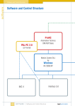
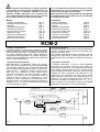
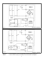
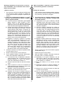
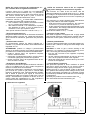
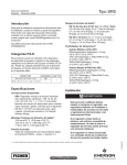
REGOLATORE ELETTRONICO RCM-2 PER GENERATORI A CONDENSATORE
ISTRUZIONI PER L’USO
RCM-2 ELECTRONIC REGULATOR FOR CAPACITOR GENERATORS
OPERATING INSTRUCTIONS
RCM-2 instruction manual - January 2010 rev. 05
1
Per un corretto funzionamento di questo regolatore
e per evitare di causare guasti all’alternatore è importante seguire le istruzioni riportate in questo
manuale. La Mecc Alte S.p.A. non si assume nessuna responsabilità per danni che possono derivare
da un utilizzo diverso da quanto qui riportato.
It is very important to follow the instructions of this
manual both for a correct working of the regulator
and to avoid damage to the alternator.
Mecc Alte S.p.A. does not assume any responsibility
for damages that could come from an use different
from that reported here.
INDICE
-) Campo di applicazione
-) Principio di funzionamento
-) Brevetto
-) Caratteristiche generali
-) Operazioni preliminari
-) Connessione ai morsetti
-) Messa in servizio
-) Precisione della tensione
-) Potenziometro esterno
-) Dimensioni di ingombro
CONTENTS
-) Field of application
-) Principle of operation
-) Patent
-) General characteristics
-) Preliminary operations
-) Connection to terminals
-) Putting into operation
-) Accuracy of the voltage
-) Remote potentiometer
-) Overall dimensions
pag. 2
pag. 2
pag. 3
pag. 3
pag. 4
pag. 4-5
pag. 6-7
pag. 8
pag. 8
pag. 8
page 2
page 2
page 3
page 3
page 4
page 4-5
page 6-7
page 8
page 8
page 8
RCM-2
-) Campo di applicazione
Il regolatore RCM-2 è un dispositivo elettronico progettato per mantenere costante la tensione generata esclusivamente dagli alternatori con regolazione a condensatore. Detto regolatore NON PUO’ essere utilizzato in
combinazione all’ecologizzatore tipo ECO2 (dispositivo
che riduce la velocità del motore quando non è applicato
nessun carico all’alternatore).
-) Field of application
The RCM-2 regulator is an electronic device designed to
produce a constant voltage output from alternators with
capacitor regulation only.
This regulator CAN NOT be used in combination with the
energy saver type ECO2 (a device that reduces the
speed of the motor when there is no load on the alternator).
-) Principio di funzionamento
Negli alternatori a condensatore, finchè non intervengono fenomeni di saturazione, la tensione dipende dalla
velocità, dalla corrente di carico e dal valore della capacità connessa sull’avvolgimento ausiliario. Si faccia riferimento alla fig. 1; fissata la velocità nominale (ad es.
3600 rpm) e la condizione di vuoto (nessun carico
connesso all’alternatore), se viene connesso il condensatore Caux, in uscita si avrà un determinato valore di
tensione V1 (per es. 200V); se, in parallelo a Caux viene
connesso un altro condensatore che chiameremo Cadd,
(risultando quindi connesso all’avvolgimento ausiliario la
capacità C = Caux + Cadd) si avrà che la tensione generata
V2 aumenterà (per es. 260V).
-) Principle of operation
In capacitor alternators, in order to avoid saturation
phenomena, the voltage is a function of the speed, the
load current, and the value of the capacitance connected
to the auxiliary winding. Refer to figure 1. Having set the
nominal speed (for example 3,600 rpm) and the no-load
condition (no load connected to the alternator), if the
Capacitor Caux is connected to the output, then a certain
value of voltage is reached V1 (for example 200V); if, in
parallel to Caux another capacitor that we will call Cadd is
connected (resulting in a capacitance of C = Caux + Cadd
being connected to the auxiliary winding), the voltage
generated will increase to V2 (for example 260V).
Syncronization signal
Error
ERROR
AMPLIFIER
DIFFER.
AMPLIFIER
CBIG
Threshold
Reference
Voltage
SYNCRO
GENER.
+
-
COMP.
+
-
COMP.
Forced Switching at Semi-period end
Switch-on Request
Auxiliary
Winding
LOGIC
POWER
SWITCH
Switch Enable
CSMALL
OUT OF RANGE
PROTECTION
ZERO
DETECTOR
Out Of Range LED
Measured Main Voltage
DIFFER.
AMPLIFIER
SENSING
Main
Winding
fig. 1
RCM-2 instruction manual - January 2010 rev. 05
2
Se mettiamo in serie al condensatore Cadd un interruttore elettronico, modulando il tempo di chiusura di detto
interruttore (ton), possiamo regolare la corrente che attraversa il condensatore stesso e quindi è come variassimo
il valore del condensatore, conseguentemente varierà
anche la tensione di uscita dell’alternatore.
Qualora venga applicato un carico, la tensione tenderà a
variare secondo la caratteristica di carico della macchina; regolando opportunamente il tempo di chiusura
dell’interruttore elettronico (ton) si regola la tensione di
macchina.
Nel normale funzionamento si ha un riscaldamento degli
avvolgimenti dell’alternatore che comporta una variazione della resistenza degli stessi e conseguentemente
una variazione della tensione di uscita; questo effetto
può essere compensato regolando opportunamente il
tempo ton.
Al variare della velocità si ha una variazione di tensione
dipendente dalla caratteristica tensione/frequenza dell’alternatore: anche in questo caso, (per piccoli scostamenti della velocità dal suo valore nominale) regolando
il rapporto ton/T si regola la tensione di macchina.
Il regolatore elettronico RCM-2 è dotato di un controllo
automatico della tensione impostata che va ad agire sul
tempo ton: in questo modo, impostato il valore della
tensione di uscita, essa viene mantenuta costante indipendentemente dal carico, dalla temperatura e, entro
certi limiti, dalla velocità.
If we put an electronic switch in series with the capacitor
Cadd, by modulating the closed time (ton) of this switch we
can control the current through the capacitor itself which
is like varying the value of the capacitor, and so in turn
the output voltage of the alternator will vary.
If a load is applied, the voltage will tend to vary according to the load characteristic of the machine; suitable
regulation of the closed time of the electronic switch (ton)
regulates the voltage of the machine.
In normal operation the windings of the alternator heat
up which causes a change in their resistance and therefore a variation in the output voltage; this effect can be
compensated by suitable regulation of the time ton.
Changing the speed changes the voltage according to
the voltage/frequency characteristic of the alternator: in
this case too (by small adjustments in speed from its
nominal value) regulating the time ton regulates the machine voltage.
The electronic regulator RCM-2 is fitted with automatic
control of the applied voltage by adjustment of the time
ton: by setting the value of the output voltage in this way,
it is held constant regardless of load, temperature, and
within certain limits, speed.
-) Brevetto
-) Patent
La richiesta di brevetto del nuovo regolatore è stata
depositata il 15 novembre 2000; essa è stata estesa
successivamente all’Europa e ai maggiori paesi extraeuropei (n° VI2000A000252).
The patent application for the new regulator was lodged
on 15 November 2000; it has subsequently been extended throughout Europe and the major countries outside
Europe (n° VI2000A000252).
-) Caratteristiche generali
-) General characteristics
Il sistema di regolazione si compone di:
The regulation system is made up of:
-) regolatore RCM-2
-) RCM-2 regulator
-) condensatore ausiliario (Caux): il valore viene determinato come indicato al paragrafo “messa in servizio”
-) auxiliary capacitor (Caux): the value is determined as
indicated in the paragraph “putting into operation”
-) condensatore addizionale (Cadd): il valore viene determinato come indicato al paragrafo “messa in servizio”
-) additional capacitor (Cadd): the value is determined
as indicated in the paragraph “putting into operation”
Le specifiche tecniche sono le seguenti :
The technical specifications are as follows:
-) tensione di alimentazione
50÷150Vac
-) supply voltage
50÷150Vac
-) precisione
1%
-) accuracy
1%
-) stabilita’ termica
2%
-) thermal stability
2%
-) max corrente sul cond. Cadd
8Amp
-) max Cadd capacitor current
8 Amp
-) tens. di picco tra i morsetti 5 e 6
650V
-) peak volt. between 5 and 6
650V
-) range regol. tensione pot. esterno ±5%
-) ext. pot. voltage regul. range ±5%
-) transitorio attacco carico
200ms
∆V < -10%
-) load application transient
200ms
-) transitorio stacco carico
400ms
∆V <+10%
-) load removal transient
400ms ∆V <+10%
N.B. : Tutte le prestazioni si riferiscono a carichi con
fattore di potenza unitario.
∆V < -10%
N.B.: All specifications refer to loads with a unitary power
factor.
RCM-2 instruction manual - January 2010 rev. 05
3
-) Operazioni preliminari (solo per generatori con
due avvolgimenti ausiliari)
ATTENZIONE:
Nel caso di alternatori con due avvolgimenti ausiliari non
collegati in parallelo, prima di utilizzare il regolatore
elettronico RCM-2, i due avvolgimenti stessi con i relativi
condensatori devono essere connessi in parallelo, ma
prima di fare ciò e necessario verificare che le tensioni ai
loro capi siano in fase. Per verificare ed ottenere questo
si connettono assieme due terminali, uno di ciascun
condensatore e, con l’alternatore in rotazione alla velocità nominale, tramite un tester impostato su Vac, si
misuri la tensione tra gli altri due terminali dei condensatori (vedi fig. 2). Il valore misurato deve risultare approssimativamente nullo (fig.2). Se non fosse così, dopo
aver arrestato la macchina, invertire il collegamento di
uno dei due avvolgimenti ausiliari senza scollegarlo dal
proprio condensatore. Una volta determinato con certezza che la tensione descritta sia circa nulla si può
procedere a collegare i due avvolgimenti con i rispettivi
condensatori, in parallelo.
1
-) Preliminary operations (only for generators having
two auxiliary windings)
NOTE:
In the case of alternators with two auxiliary windings that
are not connected in parallel, before using the RCM-2
electronic regulator, the two windings and their relative
capacitors must be connected in parallel, but before
doing that it is necessary to check that the voltages at
their ends are in phase. To make sure of this connect
together two terminals, one for each capacitor and, with
the alternator running at nominal speed, using a meter
set to Vac, measure the voltage between the other two
terminals of the capacitors (see fig. 2). The value as
measured should be approximately zero (fig. 2). If it is
not the case, stop the generator and reverse the connection of one of the two auxiliary windings without disconnecting it from its capacitor. Once it is certain that the
voltage as described is approximately zero the two
windings with their respective capacitors can be connected in parallel.
verde / green
Avvolgimenti di eccitazione
Excitation windings
C1
Condensatore principale
Main capacitor
Vac
2
verde / green
2
rosso / red
C1'
Condensatore principale
Main capacitor
fig. 2
1
rosso / red
-) Connessione ai morsetti
Con riferimento alle figure 3a e 3b (a seconda che il
generatore debba essere collegato a 230V/50Hz-240V/
60Hz o a 115V/50Hz-120V/60Hz, i terminali del regolatore
numerati da 1 a 7 vanno connessi come segue :
terminale 1) ad uno dei cavi di uscita dell’avvolgimento
principale del generatore.
terminale 2) all’altra uscita del principale (regol.230-240) o
al morsetto 1 (regol.115/120)
terminale 3) potenziometro esterno (100Kohm opzionale)
Avvolgimenti di eccitazione
Excitation windings
Alternatore
Alternator
-) Connection to the terminals
Referring to figures 3a and 3b (according to which the
generator must be connected to 230V/50Hz-240V/60Hz
or to 115V/50Hz-120V/60Hz), the terminals of the regulator numbered from 1 to 7 are connected as follows:
terminal 1) to one of the output leads of the main
generator winding.
terminal 2) to the other of the output leads (for 230-240
sensing) of the main generator winding or
to terminal 1 (for 115-120V sensing).
terminal 3) external potentiometer (optional 100 kohm
potentiometer).
terminal 4) to the central phase of the main generator
windings (230/240V sensing) or to the other
output main lead (115/120V sensing)
terminal 5) to the terminal of the capacitor Caux that is
NOT connected to Cadd
terminal 6) to the terminal of the capacitor Cadd that is
NOT connected to Caux
terminale 4) al centro fase degli avvolgimenti principali del
generatore (regolaz. a 230/240), o all’altra
uscita del principale (regolaz. 115/120)
terminale 5) al terminale del condensatore Caux che NON
è connesso a Cadd
terminale 6) al terminale del condensatore Cadd che NON
è connesso a Caux
terminale 7) al terminale del condensatore fisso Caux o al
terminale del condensatore Cadd che sono
connessi assieme
terminal 7) to the terminal of the fixed capacitor Caux or
to the terminal of the capacitor Cadd which
are connected together.
RCM-2 instruction manual - January 2010 rev. 05
4
230V-50 Hz - 240V-60Hz
fig. 3a
fig. 3b
Attenzione :
Caution :
115V-50 Hz - 120V-60Hz
in caso di regolazione a 115/120 V è indispensabile connettere assieme i morsetti 1 e 2.
in case of 115/120 V sensing, it is necessary to connect the terminal 1 and 2 together.
RCM-2 instruction manual - January 2010 rev. 05
5
Qualunque operazione di connessione o sconnessione dell’RCM-2 o dei condensatori deve essere
fatta a macchina ferma.
Before any RCM-2 or capacitors wiring operation,
ensure that the generator is stationary.
-) Messa in servizio
-) Putting into operation
1.
1.
Se la macchina ha due avvolgimenti ausiliari separati essi devono essere connessi in parallelo secondo quanto indicato al paragrafo “operazioni preliminari”.
If the machine has two separate auxiliary windings,
they must be connected in parallel as indicated in
the “preliminary operations” paragraph.
2. The value of the Caux auxiliary capacitor is to be
define experimentaly, WITHOUT CONNECTING
the RCM-2 regulator.
2. Il valore del condensatore ausiliario Caux va determinato sperimentalmente SENZA CONNETTERE il regolatore RCM-2
2.1. A seconda del tipo di alternatore, per la prima
prova, utilizzare il valore suggerito in tab.A,
qualora il tipo non sia presente utilizzare un
valore pari a circa il 70% della capacità installata
sulla macchina senza regolazione elettronica.
2.1. Depending on the type of alternator, for the
first test, use the value given in table A. If the
type is not given, use a value of around 70% of
the capacity installed on the machine without
electronic regulation.
2.2. Avviare la macchina, misurando la tensione sui
morsetti dell’avvolgimento principale, verificare
l’autoeccitazione della stessa: la tensione erogata deve essere più di 100V, se i due avvolgimenti di statore sono in serie, più di 50V se sono
in parallelo. Se questo non avviene, provare a
eccitare l’alternatore e se la tensione non raggiunge i valori sopradescritti significa che il condensatore Caux deve essere aumentato al successivo valore commerciale disponibile.
2.2. Start the machine, measuring the voltage on
the main connection terminals, check the selfexcitation of this. The voltage delivered must be
more than 100V if the two windings are in
series and more than 50V if they are in parallel.
If this does not occur, try to excite the alternator
and if the voltage does not reach the aforementioned values, this means that the Caux capacitor
must be increased to the next commercially
available value.
2.3.Regolare la velocità di rotazione al massimo
valore che si prevede di utilizzare a vuoto. Caricare progressivamente l’alternatore fino a
quando la corrente è circa metà del suo valore
nominale controllando che la tensione sia sempre inferiore al 90% del valore nominale, se a
vuoto o in qualche condizione di carico essa
supera tale valore significa che il condensatore
Caux è eccessivo e deve essere diminuito al
precedente valore commerciale disponibile.
2.3.Adjust the rotation speed to the maximum value
intended to be used at no load. Gradually load
the alternator until the current is about half its
nominal value checking that the voltage is
always less than 90% of the nominal value. If the
voltage exceeds this value at non-load or under
any load conditions, this means that the Caux
capacitor is excessive and must be reduced to
the next commercially available value down.
3.
Arrestare il sistema e connettere il regolatore RCM2 come indicato in fig. 3.
3.
Stop the system and connect the RCM-2 regulator
as indicated in Fig. 3.
4.
Ruotare il trimmer tutto in senso antiorario
4.
Rotate the trimmer anticlockwise.
5.
Con il regolatore RCM-2 connesso, determinare il
valore del condensatore addizionale Cadd
5.
With the RCM-2 regulator connected, determine
the value of the Cadd auxiliary capacitor.
5.1. A seconda del tipo di alternatore, utilizzare il
valore suggerito in tab. A, qualora il tipo non sia
presente utilizzare un valore circa uguale a
quello del condensatore ausiliario Caux.
5.1.Depending on the type of alternator, use the
value given in table A. If the type is not given,
use a value which is approximately equal to that
for the auxiliary Caux capacitor.
5.2. Portare la macchina alla sua velocità nominale a
vuoto.
5.2.Bring the machine to its nominal non-load
speed.
5.3. Tarare il trimmer in modo che la tensione sia
quella desiderata (una rotazione in senso orario
determina un aumento di tensione).
5.3.Calibrate the trimmer to obtain the desired voltage (rotate clockwise o increase the voltage).
5.4. Arrestare il motore di trascinamento quindi riavviarlo fino alla velocità nominale a vuoto.
5.4.Stop the run-in motor then restart it to obtain the
nominal non-load speed.
5.5. Verificare che nel giro di qualche secondo la
tensione si porti al valore precedentemente impostato, se rimane ad un valore inferiore a
quello impostato è probabile che il valore di Caux
sia insufficiente: esso dovrebbe essere aumentato al successivo valore commerciale disponibile, in questa eventualità deve essere ripetuta
tutta la procedura a partire dal punto 2.
5.5. Run for several seconds and check that the
previously set voltage is obtained. If it remains at
a lower value than that set, it is likely that the
Caux value is insufficient and must be increased
to the next commercially available value. In this
case, the whole procedure from point 2 must be
repeated.
RCM-2 instruction manual - January 2010 rev. 05
6
5.6. Caricare progressivamente l’alternatore fino al
suo valore nominale controllando che la tensione rimanga costante entro i limiti indicati al
paragrafo “precisione della tensione”. Se, all’aumentare del carico si verifica una cospicua
diminuzione della tensione, significa che la capacità di Cadd è insufficiente e pertanto deve
essere aumentata.
6.
5.6. Gradually load the alternator to its nominal
value, checking that the voltage remains constant between the limits indicated in the
“voltage specification” paragraph. If, on increasing the load, the voltage reduces significantly,
this means that the Cadd capacity is insufficient
and must, therefore, be increased.
6.
Se dopo un certo tempo (da 15’ a 1h), dipendente
dalle dimensioni dell’alternatore, la tensione rimane
entro i limiti specificati, si è trovato un valore adeguato di capacità per Cadd.
If, after a certain time (from 15’ to one hour),
depending on the dimensions of the alternator, the
voltage remains within the limits specified, an adequate Cadd capacity value has been found.
NOTE: This procedure must be strictly adhered to for
installation of the RCM-2 regulator, to guarantee the
correct operation of all the parts.
NOTA: Per garantire il corretto funzionamento di tutte le
parti, nell’installazione del regolatore RCM-2 deve essere scrupolosamente seguita questa procedura.
TABELLA A / TABLE A
I valori consigliati di Caux e Cadd sono da verificare sperimentalmente.
Suggested values of Caux and Cadd are to be verify experimentally.
Tipo
Type
Tens.
Voltage
V
Freq.
Freq.
Hz
Cin
Caux
Cadd
µF
µF
µF
S16W-130
115/230
50
25
16
25
S16W-150
115/230
50
31,5
25
S20W-95
115/230
50
31,5
S20W-110
115/230
50
S20W-130
115/230
S16F-150
S16F-180
Tens. Freq.
Voltage Freq.
V
Hz
Cin
Caux
Cadd
µF
µF
µF
S16W-130
120/240
60
25
16
18
31,5
S16W-150
120/240
60
31,5
20
16
25
25
S20W-95
120/240
60
40
25
31,5
35
20
35
S20W-110
120/240
60
40
25
35
50
45
31,5
31,5
S20W-130
120/240
60
40
31,5
31,5
115/230
50
25
18
25
S16F-150
120/240
60
35
25
35
115/230
50
31,5
10+12,5
31,5
S16F-180
120/240
60
31,5
20
25
S20FS-130 115/230
50
20 + 25
25
35
S20FS-130 120/240
60
2 x 25
35
31,5
S20FS-160 115/230
50
31,5+25
40
31,5
S20FS-160 120/240
60
2 x 31,5
40
40
50
2 x 35
35
35+10
60
2 x 40
40 + 14
40 + 20
S20F-200
115/230
Tipo
Type
S20F-200
120/240
Con Cin si intende il condensatore che è installato sulle
macchine di serie senza regolatore elettronico; se il
valore di Cin è diverso da quanto indicato in Tab. A, i
valori suggeriti per Caux e Cadd potrebbero non essere
corretti.
Cin means the capacitor installed on mass-produced
machines without an electronic regulator; if the Cin value
is different from that indicated in Table A, the values
suggested for Caux and Cadd may not be correct.
NOTA: Qualora la tensione venga regolata a valori
diversi da quelli indicati in tab. A, i valori Caux e Cadd
potrebbero non essere corretti.
NOTE: If the voltage value set-up is different from
the one indicated in table A, the values of Caux and
Cadd may not be correct.
I valori indicati in tabella A sono stati scelti in modo da
riutilizzare il più possibile i condensatori installati di serie
sulla macchina senza regolatore. E’ possibile che in
talune tipologie di alternatori il valore di Caux possa
essere aumentato e il valore di Cadd diminuito. Le gamme
di valori entro le quali possono essere scelti i valori di
Caux e di Cadd sono limitate dai seguenti vincoli:
The values indicated in Table A have been chosen to
use the capacitors installed on the machines in massproduction without a regulator as often as possible. It is
possible that in any type of alternator, the Caux value can
be increased and the Cadd value decreased. The ranges
of values from which the Caux and Cadd values can be
chosen are limited by the following restrictions:
Il minimo valore di Caux è quello che permette all’alternatore con regolazione elettronica di autoeccitarsi.
The minimum value of Caux is the one which allows the
alternator with electronic regulation to self-excite.
Il massimo valore di Caux è quello che con qualunque
carico connesso all’alternatore e in tutta la gamma di
velocità del motore di trascinamento (al variare del
carico) permette al regolatore RCM-2 di mantenere la
regolazione della tensione al valore impostato.
The maximum Caux value is the one which allows the
RCM-2 regulator to maintain the regulation of the voltage at the value set with any charge connected to the
alternator, throughout the range of run-in motor speeds
(with variation of the charge).
RCM-2 instruction manual - January 2010 rev. 05
7
NOTA: Un valore eccessivo del condensatore Caux
puo’ causare danni al regolatore elettronico.
NOTA: An excessive value of the Caux capacitor
may cause damages to the electronic regulator.
Il minimo valore di Cadd è quello che, con l’alternatore
caricato al suo valore nominale a cos ϕ =1, permette di
mantenere la tensione entro i limiti di precisione indicati
alla minima velocità alla quale si porta il motore di
trascinamento in questa situazione di carico.
The minimum Cadd value is the one which, with the
alternator loaded to its nominal value at cos ϕ =1, allows
the voltage to be kept between the limits specified at the
minimum speed at which the run-in motor is operating in
this load situation.
Il massimo valore di Cadd è limitato dalle caratteristiche
dello stadio di potenza del regolatore RCM-2:
• Con il massimo carico previsto, la massima corrente
su Cadd (corrente sul morsetto 6) è 8Arms
• Alla massima velocità e con l’alternatore in qualunque situazione di carico, il picco di tensione tra i
morsetti 5 e 6 non può superare i 650V.
Tutto quanto indicato si riferisce a carichi a cos ϕ = 1.
The maximum Cadd value is limited by the characteristics
of the power state for the RCM-2 regulator:
• With the maximum load provided for, the maximum
current on Cadd (current on terminal 6) is 8 Arms
• At the maximum speed and with the alternator in any
load situation, the voltage peak between terminals 5
and 6 may not exceed 650 V.
All the above relates to cos ϕ = 1 loads.
-) Precisione della tensione
Il regolatore RCM-2 è dotato di un riferimento di tensione
altamente stabile e preciso che, unitamente alla strategia di controllo in retroazione, garantisce una precisione
dell’1%.
-) Accuracy of the voltage
The RCM-2 regulator is equipped with a highly stable
and accurate reference voltage which, together with the
feed-back control system, ensures an accuracy of 1%.
-) Potenziometro esterno
Un potenziometro esterno da 100KΩ collegato tra i
morsetti 3 e 4, permette di variare il valore della tensione
impostata di ± 5%.
-) Remote potentiometer
A remote 100KΩ potentiometer connected between terminals 3 and 4, allows to change the rated voltage value
about ± 5%.
ATTENZIONE: quando si collega il potenziometro
esterno è necessario seguire la procedura sottoriportata
per ottenere un corretto funzionamento dell’alternatore.
• ruotare il trimmer VOLT nel regolatore completamente in senso antiorario
• posizionare il potenziometro esterno a metà corsa e
connetterlo agli appositi morsetti del regolatore
• tramite il trimmer VOLT del regolatore tarare la tensione al valore nominale
CAUTION: in order to get a correct working of the
alternator, it is necessary to follow the following procedure, connecting the external potentiometer.
• turn the VOLT trimmer of the regulator completely
anticlockwise.
• set the external potentiometer at half turn and connect it to the proper terminals of the regulator.
• adjust the voltage at the nominal value by the VOLT
trimmer of the regulator.
-) Protezione “Out Of Range”
La protezione interviene in quelle condizioni di velocità e
carico in cui l'RCM-2 non è è più in grado di regolare la
tensione ed essa tende ad aumentare.
L'RCM-2 può funzionare in condizioni di “Out Of Range”
per circa 20 sec. (esso ha gia perso il controllo della
tensione) dopodichè viene permanentemente disabilitato lo stadio di potenza (che regola la corrente nel
condensatore Cadd) e si accende il LED rosso "“Out Of
Range”. Generalmente il problema è dovuto ad un eccessivo valore del condensatore Caux. Per il ripristino è
necessario fermare l'alternatore e riavviarlo.
-) “Out Of Range” Protection
This protection operates in those conditions of speed
and load in which the RCM-2 in not anymore able to
adjust the voltage whose value is going to increase.
RCM2 can work in “Out Of Range” mode for about 20
sec. (RCM-2 have already lost the voltage control), then
the AC power switch (controlling Cadd capacitor current)
is permanently disabled and the red LED “Out Of Range”
is switched on.
Generally the problem is an excessive value of Caux.
The reset needs the Gen-Set switching off.
-) Dimensioni di ingombro
-) Overall dimensions
dimensions in mm
fig. 4
RCM-2 instruction manual - January 2010 rev. 05
8


![Final Report - [Almost] Daily Photos](http://vs1.manualzilla.com/store/data/005658230_1-ad9be13b69bd4f2e15f58148160b0f22-150x150.png)