1
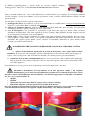
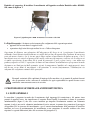
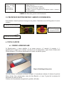
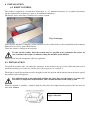
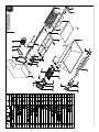
MACCHINE ENOLOGICHE
WINE PRODUCTION MACHINERY
ISTRUZIONI PER L'USO INSTALLAZIONE E MANUALE TECNICO
USER INSTRUCTIONS, INSTALLATION AND TECHNICAL MANUAL
ISTRUZIONI
PER
L'USO
INSTALLAZIONE
MANUALE
TECNICO
ISTRUZIONI
PER
L'USO
INSTALLAZIONE
EE
MANUALE
TECNICO
DIRASPATRICECON
CONMOTORE
MOTORE
DIRASPATRICE
PIGIA-DIRASPATRICE
15-25-35
ENOARNO
3ARNO
- ENO
10 - ENO 15
15-25-35
JOLLY15/E-25/E-35/E
15/E-25/E-35/E
JOLLY
ENO
ENO
2020
CRUSHER
DESTEMMER
JOLLY
20/AR-30/AR
JOLLY
20/AR-30/AR
ENO
3-ENO
10-ENO 15
JOLLY
50/A
JOLLY 50/A
BETA60-90-120
60-90-120
BETA
ENOITALIA
s.r.l.
ENOITALIA
s.r.l.
ENOITALIA s.r.l.
50050 CERRETO GUIDI (FI)
www.enoitalia.net
www.enoitalia.net
Tel.+39
0571 588031
[email protected]
[email protected]
Fax +39 0571 588080
www.enoitalia.net
ATTENZIONE:
ATTENZIONE:
[email protected]
Il presente
manuale
essere
conservato
in prossimità
della
macchina
edluogo
in luogo
conosciuto
personale
addetto
Il presente
manuale
devedeve
essere
conservato
in prossimità
della
macchina
ed in
conosciuto
dal dal
personale
addetto
50050
CERRETO
GUIDI
50050
CERRETO
GUIDI
(FI)(FI)
Tel.+39
0571
588031
Tel.+39
0571
588031
0571/588080
fax fax
+39+39
0571/588080
operazioni
di utilizzo,
manutenzione
e riparazione
allealle
operazioni
di utilizzo,
manutenzione
e riparazione
ATTENZIONE:
Il presente manuale deve essere conservato in prossimità della macchina ed in luogo conosciuto dal personale addetto
alle operazioni di utilizzo, manutenzione e riparazione.
WARNING:
This manual should be kept near the machine in a place known to personnel responsible for operating, servicing and
repairing the machine.
I
1. INDICE
1. INDICE.....................................................................................................................
2. CONTENUTO DEL VOLUME...............................................................................
T
3. NORME DI SICUREZZA .......................................................................................
4. DESCRIZIONE MACCHINARIO .........................................................................
A
5. PROTEZIONI ANTINFORTUNISTICHE E RISCHI ..........................................
L
7. LAVAGGIO E PULIZIA PRIMA INSTALLAZIONE..........................................
I
9. AVVIAMENTO ED ARRESTO..............................................................................
A
11. PROBLEMI E SOLUZIONI ...................................................................................
N
O
6. INSTALLAZIONE...................................................................................................
8. COLLEGAMENTO ELETTRICO ........................................................................
10. LAVAGGIO E MANUTENZIONE.........................................................................
12. CARATTERISTICHE TECNICHE........................................................................
13. GARANZIA..............................................................................................................
14. DICIARAZIONE DI CONFORMITA’ CE ..........................................................
DISEGNO COMPONENTI TECNICI (ALLEGATO)......................................................
2. CONTENUTO DEL VOLUME
Questo volume contiene tutte le informazioni accompagnate da disegni e/o schemi necessarie per
l'installazione, l'esercizio la manutenzione delle Pigiadiraspatrici.
Inoltre stabilisce le norme di sicurezza che il personale addetto alla macchina deve rispettare.
Questo volume è destinato a: Responsabili dello stabilimento o del reparto; Personale addetto
all’installazione; Personale operatore di macchina; Personale addetto alla manutenzione
E' vietato l'esercizio e la riparazione della macchina da parte di persone che non abbiano
letto ed assimilato le precauzioni di sicurezza contenute nel presente manuale. Il
manuale costituisce parte integrante del macchinario, deve essere reso disponibile per la
consultazione in maniera facile e veloce. Il manuale deve essere riposto in un luogo idoneo,
che non pregiudichi lo stato di conservazione del manuale stesso..
In particolare:
• posizionare in un luogo pulito ed asciutto, e darne comunicazione a tutto il
personale a cui è destinato il presente manuale
• non tentare di riscrivere parte del manuale.
3. NORME DI SICUREZZA
LA DEROGA ALLE REGOLE PRESENTI PUÒ ESSERE CAUSA DI PERICOLO CON
RISCHIO DI INCIDENTI PER IL PERSONALE E DANNI ALLA MACCHINA
Prima di iniziare qualsiasi attività operativa sul macchinario è necessario leggere quanto espressamente
indicato dal manuale, ed è obbligatorio integrare le norme qui riportate con gli obblighi previsti dalla
legislazione vigente in materia di sicurezza e antinfortunistica.
Gli organi in movimento del macchinario possono essere causa di incidenti anche gravi si richiede la massima
prudenza quando il macchinario è in funzione, inoltre il posizionamento della pigiadiraspatrice in un luogo
umido comporta rischi per scariche elettriche accidentali causate dai contatti elettrici del motore.
Furthermore, the positioning of the crusher-destemmer in a wet location constitute a risk to accidental electric
shocks caused by the electrical contacts of the motor.
Pertanto la Enoitalia s.r.l. declina ogni responsabilità in caso di :
• Inadeguatezza degli impianti elettrici utilizzati per azionare il macchinario
• Inadeguatezza delle condizioni ambientali in cui si trova a lavorare il macchinario
• Mancata applicazione delle norme di installazione, uso e manutenzione, indicate nel presente manuale
• Utilizzo del macchinario da parte di personale non addetto e non qualificato
• Modifiche del macchinario non autorizzate
Le uniche destinazioni d’uso previste per il macchinario sono quelle espressamente indicate nel
manuale. La Enoitalia s.r.l declina ogni responsabili per impieghi del macchinario diversi da quanto
previsto.
4. DESCRIZIONE DEL MACCHINARIO
4.1. AVVERTENZE:
La Pigia-Diraspatrice fornita deve essere utilizzata esclusivamente per le lavorazioni del prodotto
descritto nel presente manuale
• Non iniziare il montaggio della Pigia-Diraspatrice o metterla in esercizio prima di un'attenta lettura
del presente manuale
• Non azionare la Pigia-Diraspatrice se una o più etichette di avvertimento sono danneggiate o
risultano mancanti
• Non azionare la Pigia-Diraspatrice se la macchina ha vibrazioni anomale, e se le protezioni fornite
non sono state applicate
• Non effettuare le operazioni di manutenzione, smontaggio e pulizia prima che la macchina sia
completamente ferma e i collegamenti elettrici disinseriti da alcuni minuti
• Non far funzionare il macchinario se i motori elettrici, o la struttura presentano incrinature.
Controllare almeno una volta l’anno che il fissaggio delle varie componenti sia regolare, ed
eventualmente procedere a stringere i bulloni/dadi allentati
• Controllare se la tensione del circuito alla quale è collegato il quadro di comando dei motori è la
stessa di quella prevista dal cablaggio dei motori
• Non tentare di far funzionare un motore surriscaldato. Lasciare raffreddare il motore alla
temperatura ambiente
• Utilizzare solamente personale esperto per mettere in esercizio, pulire e fare manutenzione sul
macchinario
• Non avviare i motori se non girano liberamente gli elementi rotanti
• Utilizzare imbracature per sollevare il macchinario ed accertarsi che queste siano adeguate al peso
da sollevare
• Lavare il macchinario solo con prodotti atossici e di uso alimentare
• Il presente libretto deve sempre accompagnare la macchina, ed è vietata qualsiasi tipo di
riproduzione, anche parziale.
•
4.2. DESCRIZIONE
La Pigiadiraspatrice è un macchinario destinato alla pigiatura e diraspatura dell’uva, idonea all’impiego in
piccole medie cantine.
I modelli a cui fa riferimento il presente manuale sono i seguenti:
1) ENO 3/V pigiadiraspatrice a volano nelle tre versioni: lamiera smaltata; tramoggia
inox; tutta inox . Codice 521/522/525
2) ENO3/M pigiadiraspatrice a motore nelle tre versioni: lamiera smaltata, tramoggia
inox, tutta inox. Codice 523/524/526
3) ENO 10 diraspatrice a motore nelle due versioni: lamiera smaltata; tutta inox.
Codice 012/212
4) ENO15 pigiadiraspatrice a motore nelle tre versioni: lamiera smaltata;
tramoggia inox; tutta inox. Codice 023/025/024/026/027/028/223/225/224
Tutti i modelli indicati ed i vari codici differiscono esclusivamente per l’impiego dei materiali utilizzati
(acciaio smaltato, acciaio inossidabile) e per la produzione oraria, essendo il funzionamento identico in tutti
questi modelli
La macchina è composta dalle seguenti componenti:
1) tramoggia di carico, al cui interno si trova sul modello ENO 15 ed ENO 10 la coclea per il trascinamento
dell’uva,
Tramoggia di carico
Uscita raspi e sul modello ENO 3 ed ENO 3/M l’agitatore
2) rulli per la pigiatura dell'uva, dotati di molla inox(il modello ENO 10 è privo di rulli). La regolazione
dei rulli può avvenire agendo sull'apposito dado (figura 10).
3) rete di diraspatura, che permette la separazione degli acini dai raspi,
per mezzo della rotazione
Carter protezione motore
dell’albero di diraspatura . Gli acini separati ed il succo ottenuto dalla pigiatura dei rulli vengono raccolti
in un contenitore posizionato sotto il macchinario.
4) uscita raspi: i raspi vengono eliminati per caduta nella parte terminale della macchina. Devono essere
Tubolare
di sostegno
tolti solamente i raspi caduti a terra, e non quelli eventualmente depositati
nelle
lamiere di scarico della
macchina. Per togliere questi ultimi occorre arrestare la macchina, disinserire la presa elettrica dalla
corrente e procedere all’estrazione.
Carter protezione
NON EFFETTUARE
Uscita aciniMAI
e succoTALE
diraspatore
OPERAZIONE
CON IL MACCHINARIO ACCESO
Motore elettrico
5) motore elettrico dotato di pulsante di arresto di emergenza, cavo e spina (nella versione
Figura n.4 Descrizione Diraspatrice (nella figura il modello ENO 10)
monofase). E’ necessario che l’impianto elettrico dell’utilizzatore sia conforme alle norme di legge in
vigore, e che si tenga conto dell’assorbimento massimo di corrente previsto per il macchinario.
6) cassonetto di protezione antinfortunistico:deve essere posizionato sulla sommità della tramoggia.
Tale protezione è necessaria per impedire l’accesso degli arti superiori alla zona di azione della coclea
Tramoggia di carico
Carter
protezione
e dei
rulli.
(figura 1)
diraspatore
La macchina deve essere posta su di un recipiente per la raccolta degliCarter
aciniprotezione
e del succo.
motore
Uscita raspi
Attenzione l’installazione del macchinario su di una superficie stabile è un requisito
fondamentale per la sicurezza nell’utilizzo del prodotto.
Si raccomanda di procedere con Rulli
la
Tubolare di sostegno
massima cautela nell’installazione del macchinario e nel suo bloccaggio sopra il contenitore selezionato,
che deve avere caratteristiche di:
acini e succo
•Uscita
rigidità
• stabilità
Supporto
rullimacchinario
Motore elettrico
• robustezza
(ilregolazione
peso del
a pieno carico è diCassonetto
circa 130
kg)
antinfortunistico
• dimensioni adeguate (vedi paragrafo 5.1 Protezioni di Sicurezza)
Nel caso di impiego di contenitori circolari in plastica il diametro non deve essere superiore a 800mm,
ed il macchinario va bloccato con apposite cinghie (non fornite)
come
indicato nella foto:
Cavalletto
di supporto
Figura n.1 Descrizione Pigiadiraspatrice (nella figura il modello ENO15)
Enoitalia srl suggerisce di installare il macchinario sull’apposito cavalletto Enoitalia codice 008-009010, come da figura n° 5
Figura n°5 pigiadiraspatrice ENO 15 installata su cavalletto codice 010
La Pigia-Diraspatrice è destinata esclusivamente allo svolgimento delle seguenti operazioni:
• pigiatura dell’uva mediante la coppia di rulli
• separazione degli acini dai raspi mediate la rete e l’albero diraspatore
Suggeriamo di effettuare una valutazione dell’adeguatezza del luogo in cui è posizionato il macchinario
valutando: il macchinario risulti facilmente accessibile da ogni lato ed in particolare il pulsante di emergenza
posto sul motore elettrico; che vi sia uno spazio libero attorno al macchinario di almeno un metro, e che il
macchinario non crei ostacolo al passaggio di carrelli o altri mezzi di trasporto; verificare che il solaio su cui
si andrà a posizionare la macchina sia in grado di sostenerne il peso a pieno carico e non abbia una
pendenza superiore al 10%; l’esposizione al rumore del macchinario sia distribuita tra gli operatori in modo
da rimanere nei limiti previsti dalle normative vigenti; la temperatura ,l‘umidità, ed i campi magnetici, siano
tali da non creare danni al macchinario e da garantirne il corretto funzionamento; l’illuminazione sia
adeguata allo svolgimento ottimale delle operazioni.
Eventuali variazioni delle condizioni di impiego della macchina, sia in termini di prodotti lavorati
che di operazioni svolte, sollevano il costruttore da ogni responsabilità in quanto devono essere
considerate come una nuova messa in servizio.
5 PROTEZIONI DI SICUREZZA ED ANTINFORTUNISTICA
5.1. NOTE GENERALI
La macchina è progettata in modo che il movimento degli ingranaggi di trasmissione e del motore siano
protetti da appositi carter, che impediscono il contatto diretto. Inoltre la macchina è dotata di cassonetto
antinfortunistico (figura 1) che deve essere installato per impedire l'involontario contatto con l'elemento
ruotante (coclea), ma non la volontaria introduzione di arti o attrezzi, in quanto deve permettere il passaggio
del prodotto. Per la sicurezza del macchinario, e per il corretto funzionamento delle protezioni di sicurezza
installate, nel caso di posizionamento del macchinario su un contenitore di raccolta verificare che siano
rispettate le seguenti dimensioni (oltre alle avvertenze del paragrafo 4.2)
Figura n°6 dimensioni per installazione su
contenitori di raccolta
Lamiera bloccaggio macchinario
E’ vietato introdurre arti o attrezzi quando la macchina è in movimento.
Il datore di lavoro, o il responsabile della ditta utilizzatrice del macchinario, sono obbligati ad accertare che
tutto il personale addetto ad utilizzare le Pigiadiraspatrice sia informato sulle norme di sicurezza relative
all’utilizzo del macchinario, ed devono fornire tutte le informazioni necessarie a garantire un utilizzo in
sicurezza.
In particolare dovranno verificare che :
• non vengano eseguite manomissioni o modifiche sul macchinario
• il macchinario sia utilizzato per l’impiego previsto dal presente manuale
• che il macchinario rispetti la configurazione originaria
• che siano rispettate le norme antinfortunistiche previste dalla normativa vigente e quelle espressamente
indicate nel presente manuale
Da un analisi dei rischi connessi all’utilizzo della Pigiadiraspatrice è emerso che i principali sono i seguenti.
Figura n.7 Indicazioni di pericolo e precauzioni
Schiacciamento e/o
cesoiamento arti
superiori
Schiacciamento
arti inferiori
Coclea di
trascinamento
Rulli di pigiatura
Albero diraspatore
Organi di
trasmissione
Caduta
della
macchina
Non rimuovere le protezioni di sicurezza
Arrestare il macchinario e disinserire la spina elettrica dalla rete. Per
qualsiasi operazione di manutenzione e pulizia.
Non effettuare interventi di riparazione con il macchinario in movimento.
Utilizzare scarpe protettive antinfortunistiche
Assicurarsi della stabilità della macchina, in particolare per ciò che riguarda
il posizionamento sui contenitori di raccolta uva pigiata (vedi paragrafo
posizionamento)
olgorazione
per Motore elettrico
contatto con parti
alimentate
con
energia elettrica.
Pericolo Incendio
Controllare che la tensione di rete sia compatibile con quanto riportato sulla
targhetta del motore
Controllare l’integrità dei cavi elettrici
Proteggere il motore elettrico dall'umidità
Autorizzare operazioni di riparazione sull’impianto elettrico solamente a
personale qualificato
TABELLA 1: Riassunto generale rischi di infortunio
5.2. PROTEZIONI ELETTRICHE PER L’ARRESTO DI EMERGENZA
Il macchinario è dotato del pulsante di emergenza che permette l’immediato arresto dell'erogazione di corrente
al motore.
1) Pulsante di arresto ROSSO
3) Pulsante di arresto
di emergenza ROSSO
Per motori
si ha:
2) Pulsante
di monofase
avvio VERDE
6. INSTALLAZIONE
6.1. VERIFICA PRELIMINARE
La Pigiadiraspatrice è fornita imballata al cui interno troverete: n°1 manuale di istruzioni; n° 1
pigiadiraspatrice completa già assemblata, corredata di cavo di alimentazione e spina elettrica Schuko (nella
versione monofase). Il cassonetto antinfortunistico è fornito con imballo separato.
Figura 8. Imballaggio diraspatrice
Una volta sballato il macchinario verificarne l’integrità ed eventualmente informare il fornitore di qualsiasi
difetto evidente. Dare comunicazione scritta alla ditta Enoitalia s.r.l entro 15 giorni dal ricevimento del
macchinario dei difetti riscontrati.
Verificare che il macchinario corrisponda alle specifiche dell’ordine.
Per estrarre il macchinario porre attenzione alle norme di sicurezza nella movimentazione
delle merci. Se si utilizzano mezzi automatici di sollevamento porre attenzione al
bilanciamento dei pesi. Se la movimentazione viene effettuata manualmente accertarsi di
sollevare il macchinario per le apposito tubolare di sostegno
Procedere allo smaltimento degli imballaggi a norma di legge.
6.2. POSIZIONAMENTO
Nel posizionare la Pigiadiraspatrice dovrà essere posto attenzione a quanto già indicato precedentemente sulla
scelta e adeguatezza del luogo, ed inoltre dovrà essere posta attenzione alla scelta del recipiente sopra il quale
posizionare il macchinario (vedi paragrafo 4.2) e sulle dimensioni da rispettare (vedi paragrafo 5.1)
L’altezza a cui porre il macchinario deve essere tale da impedire all’operatore di accedere con gli arti superiori
alla coclea e ai rulli posizionati all’interno della tramoggia di carico.
A tal proposito si ricorda che è OBBLIGATORIO installare il cassonetto antinfortunistico
sopra il macchinario come da paragrafo 4.2, in quanto il cassonetto costituisce parte
integrante del macchinario, e dotazione di serie per la sicurezza dello stesso
Tenuto conto dell’altezza del cassonetto, una volta posizionato il macchinario l’estremità del cassonetto deve
essere minimo a 1600 mm da terra.
Figura n°9 Sistema di
assemblaggio del cassonetto
antinfortunistico
7. LAVAGGIO E PULIZIA DELLA MACCHINA PRIMA INSTALLAZIONE.
Provvedere al lavaggio completo della macchina per eliminare tutti i residui di lavorazione e la polvere
accumulata sulla superficie, facendo attenzione a non bagnare le parti elettriche e tenendo il cavo di
alimentazione staccato dalla linea.
Una volta effettuato il lavaggio procedere all’installazione del cassonetto antinfortunistico (come indicato
nella figura n° 9).
Se le parti elettriche vengono bagnate, procedere all'immediata asciugatura completa prima di procedere con
l'avvio della Pigiadiraspatrice.
8 COLLEGAMENTO ELETTRICO
Prima di collegare la spina del motore alla rete elettrica verificare il voltaggio del motore indicato nella
targhetta corrisponda a quello della rete.
La sicurezza elettrica di questa macchina è consentita solo nel caso sia collegata ad un efficace impianto
di messa a terra, eseguito secondo le vigenti normative elettriche.
La verifica e l’eventuale installazione degli opportuni componenti elettrici deve essere effettuata da personale
qualificato.
E’ sconsigliato l’utilizzo di prese multiple o adattatori; qualora il loro impiego si rendesse indispensabile è
necessario utilizzare solamente dei prodotti conformi alle vigenti norme di sicurezza, rispettando il limite di
portata in valore di corrente e quello di massima potenza. É consigliabile usare un cavo elettrico di sezione 1,5
mm per prolunghe fino a 20 m, e di sezione 2,5 per lunghezze superiori
9 AVVIAMENTO ED ARRESTO
Prima di procedere all'avviamento l'utilizzatore deve assicurarsi che non ci siano
impedimenti che ostacolino il naturale moto degli organi meccanici e soprattutto assicurarsi
che nessuno sia in prossimità degli organi che entrano in movimento; in particolare che
nessuno abbia mani, braccia o altre parti del corpo in prossimità della bocca di scarico dei raspi o
all'interno del cassonetto. Controllare inoltre che il voltaggio del motore corrisponda a quello della rete.
Verificare che tutte le protezioni di sicurezza siano installate sul macchinario.
Verificare che il pulsante di arresto di emergenza funzioni correttamente
Se da questa verifica preliminare si riscontrassero dei problemi o degli esiti negativi nei controlli, arrestare il
macchinario, staccare la spina dalla rete elettrica, avvisare il responsabile del reparto, od eventualmente la
ditta fornitrice o Enoitalia s.r.l.
Qualora la verifica preliminare avesse esito positivo procedere come segue:
• premere il tasto sul pannello di controllo del motore elettrico e la macchina si metterà in moto
• caricare attraverso il cassonetto antinfortunistico i grappoli di uva
• il macchinario procede a trascinare i grappoli verso i rulli e successivamente verso la rete di
diraspatura. L’uva diraspata e pigiata andrà a cadere nel recipiente di raccolta ed i raspi usciranno dalla
parte posteriore del macchinario all'esterno del recipiente.
• per arrestare il macchinario premere il pulsante rosso di emergenza
• Per mettere in funzione il macchinario dopo avere sbloccato il tasto di emergenza, premere la leva di
chiusura ed aprire l’interruttore. Premere il tasto di marcia.
Qualora si rendesse necessario un intervento all'interno del corpo della macchina (intasamenti o corpi estranei)
provvedere come segue:
1. spegnere la macchina e scollegare il cavo di alimentazione
2. attraverso un attrezzo togliere il corpo estraneo e se necessario aprire la macchina
3. richiudere tutte le parti eventualmente aperte e ripetere tutte le operazioni previste per l'avviamento.
E’
vietato
introdurre
arti
o
attrezzi
quando
la
macchina
è
in
movimento.
10. LAVAGGIO E MANUTENZIONE
Dopo l'uso della macchina ed in ogni caso alla fine della giornata di lavoro, ricordarsi di interrompere
l'allacciamento di energia elettrica disinserendo l'interruttore generale e staccando la spina dalla presa.
Questa operazione è obbligatoria per evitare l'avviamento accidentale della macchina, che può causare sia
danni alla macchina stessa che alle persone.
Staccata la spina dalla rete elettrica, procedere al lavaggio per eliminare i residui della lavorazione, avendo
cura di non bagnare i componenti elettrici.
Per effettuare un lavaggio ottimale occorre aprire la macchina e togliere la rete di deraspatura
Il lavaggio del macchinario deve essere effettuato con acqua calda a pressione e detergenti neutri.
Terminato il lavaggio se la macchina deve essere messa a riposo per un lungo periodo occorre procedere alle
seguenti operazioni di lubrificazione:
• ad ingrassare tutte le catene, e gli organi di moto
• Lubrificare gli ingranaggi, i supporti dei cuscinetti, ed i supporti in teflon
• Lubrificare i rulli di pigiatura
• Lubrificare la coclea di alimentazione, l’albero di diraspatura.
Lo svolgimento accurato delle operazioni di manutenzione sopra descritte, permette un prolungamento delle
durata delle componenti soggette ad usura. Per migliorare la gestione di tali operazioni suggeriamo di
registrare le date dell’intervento di manutenzione e la descrizione dell’intervento effettuato.
Qualsiasi intervento di manutenzione deve essere svolto da personale qualificato ed
autorizzato o direttamente da Enoitalia s.r.l. Impiegare prodotti lubrificanti idonei a venire a
contatto con prodotti alimentari
E’ in ogni caso vietato smontare il motore elettrico. In caso di necessità rivolgersi al fornitore oppure alla
Enoitalia s.r.l.
Nel caso di eventuali operazioni di riparazione è necessario utilizzare i ricambi originali rivolgendosi al
rivenditore o direttamente al fabbricante
L’impiego di parti di ricambio non originali e non autorizzate da Enoitalia s.r.l, comporta il
decadimento della garanzia e della Dichiarazione di Conformità del macchinario
11.POSSIBILI CAUSE DI MALFUNZIONAMENTO
INCONVENIENTI
RIMEDI
La macchina parte con Controllare che la macchina sia alimentata dalla giusta tensione di rete
difficoltà
Non impiegare prolunghe di sezione insufficiente che possono provocare cadute
di tensione
Controllare la tensione delle cinghie di trasmissione tramite l'apposito registro
La macchina non parte
Verificare che la spina elettrica sia inserita, che non siano bruciati i condensatori
Gli acini non vengono Verificare che gli ingranaggi di trasmissione siano integri e ben bloccati
pigiati
sull’albero del rullo
Regolare la distanza tra i rulli con l’apposita vite di registro posta sul supporto
La coclea della vasca di Verificare la catena di trasmissione
raccolta non si muove
Vite registro rulli
Figura n.10 rulli regolabili
12.CARATTERISTICHE TECNICHE
La targhetta apposta sulla macchina riporta le informazioni identificative del produttore e del macchinario
Dimensioni LxPxH mm
Peso
Produzione oraria kg/h
Dimensioni tramoggia mm
Dimensione rulli mm
Motore elettrico
Velocità motore
Tensione e frequenza elettrica
Temperatura
di
funzionamento
ENO 3/V
1210 x 500 x 690
40 kg
800
1000 x 500
220
--1400 rpm
230 V -50 Hz
4 C°-50 C°
ENO 3/M
1210 x 600 x 690
51 kg
1000
1000 x 500
220
0,75 KW (1,0 HP)
1400 rpm
230 V -50 Hz
4 C°-50 C°
ENO 10
1210 x 550 x 630
40 kg
1000
1000 x 630
220
0,75 KW (1,0 HP)
1400 rpm
230 V -50 Hz
4 C°-50 C°
ENO 15
1210 x 550 x 630
40 kg
1000
1000 x 630
220
0,75 KW (1,0 HP)
1400 rpm
230 V -50 Hz
4 C°-50 C°
Rumore: Leq ponderato A 78,9-83,8 db. (rilievi in ambiente esterno in condizioni di lavoro abituali, in accordo con
la metodica indicata in UNI EN ISO 11202)inferiore ai limiti previsti dalla normativa 2006/95 CEE (<85 dB)
13. GARANZIA
La garanzia copre il macchinario per i primi dodici mesi dalla messa in funzione. In caso di mancato
utilizzo immediato la garanzia copre fino a diciotto mesi dalla data di consegna, e successivamente
decade.
La garanzia non riguarda il trasporto della macchina che è a cura dell’acquirente e decade in caso di utilizzo
non conforme a quanto indicato nel manuale.
La riparazione si intende franco nostro stabilimento di Cerreto guidi,(FI); non riguarda il trasporto che è a cura
dell'acquirente.
Sono esclusi da garanzia, comportando la cessazione da qualsiasi obbligo i difetti dipendenti da:
•
Errata installazione
•
manomissione del macchinario
•
inesperienza, mancata manutenzione, intempestiva segnalazione dei difetti.
•
Inosservanza di quanto previsto nel presente manuale di istruzione.
•
Riparazione da parte di personale non autorizzato da Enoitalia s.r.l.
•
Danni di trasporto, che non possono farsi risalire a difetti di fabbricazione o di imballaggio.
•
Interventi di installazione ed alloggiamento in impianti elettrici diversi dalle indicazioni riportate sul
manuale e sulla targhetta riportata sul motore.
•
Spese e rischi di trasporto nel caso di invio del macchinario presso centri di assistenza autorizzati.
•
Componenti elettrici.
•
Materiali di consumo e costi di manutenzione ordinaria presenti nel suddetto manuale.
La garanzia non si estende all'obbligo di risarcire danni a cose o persone derivanti dall'impiago del nostro
prodotto anche in caso di rottura o difetto.
Comportano l'immediata cessazione degli obblighi di garanzia, l'inadempienza delle condizioni di pagamento
concordate.
Tutti gli eventuali reclami dovranno essere comunicati dal compratore entro 8 giorni dall'acquisto, in forma
scritta, a ENOITALIA s.r.l.
Riserva di proprietà, come previsto dagli art. 1523-1524 eseguenti del codice civile, il trasferimento di
proprietà dei beni oggetto della vendita avverrà solo dopo il completo pagamento di quanto concordato.
Il foro competente per qualsiasi controversia dovesse venir fuori dal presente contratto è quello di Firenze.
Anche se concittadini esteri o merce fornita all'estero, ogni controversia è regolamentata dalla legislazione
italiana.
Dichiarazione CE di Conformità per le Macchine
Dichiarazione costruttore
CE di Conformità
per le Macchine
e venditore della macchina
ENOITALIA s.r.l.
Via Prov. Pisana, 162 Cerreto Guidi (FI)
costruttore e venditore della macchina
ENOITALIA
s.r.l.
MODELLO
Via Prov. Pisana, 162 Cerreto Guidi (Fi)
ENO 3/M-10-15
MODELLO
Pigiatrice-Diraspatrice
ARNO 15-25-35 / JOLLY 15/E-25/E-35/E
ENO 20 JOLLY 50/A BETA 60-90-120
Anno di costruzione: 2015
Pigiatrice-Diraspatrice
Anno di costruzione: 2014
L'azienda firmataria della presente DICHIARA sotto la sua responsabilità che la
macchina
a cui la della
presente
dichiarazione
si riferisce
è conforme
alle prescrizioni:
L'azienda
firmataria
presente
DICHIARA
sotto la sua
responsabilità
che la
•
Della
direttiva
2006/42/CE
(direttiva
macchine)
e
successive
modifiche e
macchina a cui la presente dichiarazione si riferisce è conforme alle prescrizioni:
disposizioni
nazionali di(direttiva
attuazione.
• Della
direttiva 2006/42/CE
macchine) e successive modifiche e
•disposizioni
Della direttiva
2006/95/CE
(direttiva bassa tensione) e disposizioni nazionali di
nazionali di attuazione.
attuazione.
• Della
direttiva 2006/95/CE (direttiva bassa tensione) e disposizioni nazionali di
•attuazione.
Della direttiva 2004/108/CE (direttiva compatibilità elettromagnetica) e
disposizioni
nazionali di attuazione.
• Della
direttiva 2004/108/CE
(direttiva compatibilità elettromagnetica) e
disposizioni nazionali di attuazione.
La macchina è inoltre conforme Norme Armonizzate:
La
macchina
inoltre conforme
Norme
Armonizzate:
UNI EN : 349; 954/1;
1050; è547-1-2-3
; 894-1-2-3
; 953;
981; 1005-1-2-3-4-5; 1037.
UNI
EN
:
349;
954/1;
1050;
547-1-2-3
;
894-1-2-3
;
953;
981;
1005-1-2-3-4-5;
1037.
UNI EN ISO: 3744; 7000; 12100-1-2; 11202; 11205 ; 11688-1-2;
14121-1;
13857;
UNI
EN
ISO:
3744;
7000;
12100-1-2;
11202;
11205
;
11688-1-2;
14121-1;
13857;
UNI EN ISO 1186.
UNI
EN ISO
1186. tecniche CEI EN 60204/1.
Norme
e specifiche
Norme
e
specifiche
tecniche
CEI ENnazionali:
60204/1. UNI ISO 1819; UNI ISO 7149;
Norme e specificazioni
tecniche
Norme
e
specificazioni
tecniche
nazionali:
UNI ISO 1819; UNI ISO 7149;
UNI 7544; 45020; 60447; 60447.
UNI 7544; 45020; 60447; 60447.
Cerreto
Guidi
01/01/2014
Cerreto
Guidi
01/01/2015
Il Responsabile di produzione
Falorni Fabio
Il Responsabile di produzione
Falorni Fabio
...............................................
}}
}
}
1. INDEX
1. INDEX ......................................................................................................................
2. CONTENT................................................................................................................
3. SAFETY RULES......................................................................................................
4. DESCRIPTION ........................................................................................................
5. SECURITY GUARDS..............................................................................................
6. INSTALLATION .....................................................................................................
7. WASHING AND CLEANING FIRST INSTALLATION .....................................
8. WIRING CONNECTION .......................................................................................
9. START AND STOP..................................................................................................
10. CLEANING AND MAINTENANCE ......................................................................
11. PROBLEM SOLVING ............................................................................................
12. THECNICAL FEATURE ........................................................................................
E
N
G
L
I
S
13. GUARANTEE ..........................................................................................................
14. CE DECLARATION OF CONFORMITY ...........................................................
DRAWING AND WIRING CONNECTION (ATTACH)..................................................
H
4. DESCRIPTION
4.1. ADVICES:
The crusher must be used exclusively for the processing of the product described in this manual
Don’t start to install or to use the machine before the reading of this manual
Don’t start the machine if there are missing labels
Don’t start the machine if there are not safety protection or abnormal vibration, or if the safety
protection are not installed
• Do not start the machine if the electrical motors and/or the structure of the machine are damaged.
• At least once a year ensure that the various machine components are secured and if necessary
tighten any loose nuts/bolts.
• Ensure that the circuit tension to which the engines’ control panel is connected is the same as that of
the engine cabling.
• Don’t use the machine if the motor is overheating. Wait till the motor is became cold
• Use only experienced personnel to put in operation, clean and do maintenance on machinery
• Do not start engines if the rotating elements are prevented from rotating freely.
• When using slings to lift the machine, make sure these are suitable to the weight to be lifted
• Wash and clean the machine only with no-toxic products
• This book let must always accompany the machine. Any reproduction including partial
reproduction of the same is forbidden.
•
•
•
•
We thank you for choosing our machine and have pleasure in enclosing this use and maintenance
manual to allow you to make the best use of the machine thus extending its service life.
.
4.2. DESCRIPTION
This machine can be used only for pressing and destemming Grape, suitable to be used by small winery or
family use.
.
The models referenced in this manual are as follows:
1) ENO 3/V manual destemmer crusher in 3 version: painted, hopper in inox; all in
inox . Code: 521/522/525
2) ENO3/M motorized destemmer crusher in 3 version: painted, hopper in inox; all in
inox . Code 523/524/526
3) ENO 10 motorized destemmer, in two version paited; all inox . Code 012/212
4) ENO15 motorized destemmer crusher in 3 version: painted, hopper in inox; all in
inox . Code 023/025/024/026/027/028/223/225/224
2. CONTENT
This volume contains all the information accompanied by drawings and/or diagrams necessary for
installation, operation andmaintenance of the crusher-destemmer. It also establishes safety standards that
staff must respect the machine.
This volume is intended for: the establishment or departmentmanagers, staff involved with the installation, the
machine operatorstaff, maintenance personnel
It is forbidden operation and repair of the machinery by persons who have not read
and assimilated the safety precautions contained in this manual. The manual is part of the
machinery, and it must be made available for an easy and fast consultation .
The manual must be stored in a suitable place, which does not adversely affect the
conservation status of the manual particularly
In particular :
• Place in a clean, and dry location, and communicate this place to all staff
• It is forbidden to write part of the manual
3. SAFETY RULES
FAILURE TO RESPECT THESE INSTRUCTIONS IS DANGEROUS AS IT MAY CAUSE
INJURIES TO PEOPLE AND DAMAGE TO THE MACHINE
Before to use the machine is necessary to read this manual, and it is obliged to integrate these indication with
all the valid regolamentation about safety and accident prevention.
The driving gear may cause accident . It is necessary to use caution when the machine is working,
Enoitalia s.r.l. decline any responsabilità in case of :
• Inadequancy of the electrical system used for the machine
• Inadequancy of the location where the machine is installed
• Not respect of the indication for installation, use and maintenance, as indicated in this manual
• Usemotorized
of the machine
by notcrusher
qualified
4) ENO15
destemmer
in operator
3 version: painted, hopper in inox; all in
Not 023/025/024/026/027/028/223/225/224
allowed modification to the machine
inox •. Code
The only use of the machine is the one indicate in this manual. Enoitalia srl decline all the responsibility
for any different use of the machinery
All the model mentioned in this manual are different only for the dimension, the material used (painted iron,
stainless steel) and hourly production, but they work all the same
The machine is composed by the following part:
1) Hopper for loading of the grape or fruit: inside there is an agitator (for the model ENO 15- ENO 10), or
an agitator (for the model ENO 3/V ENO 3/M.
2) Roller for press: are made in alluminium or in rubber (the model ENO 10 is without roller). They are
install on a support with a spring in the middle. This spring allows self adjustment of the roller (i.e. there
is a solid part the roller move, and the gear are not broken). To regulate the space between the roller it is
possible to use the bolt (Fig. n°10)
3) Basket: allows the separation of the berries from the stems, by means of rotation of the shaft. Juice and
berries are collected in a container placed under the machine
4) Stem exit : the stems are removed by gravity in the terminal part of the machine. Only the fallen
stems should be removed , and not those eventually deposited in the sheet of the machine. To
remove them you must stop the machine, disconnect the electrical plug from power and extracting
Never do this operation with the machine on
5) Engine: it is supplied with emergency stop, cord and plug (on the monophase version). It is necessary that
the circuit tension and the system of the user is conformed to the regulamentation , and must be suitable
compare with the label of the motor
6) Hopper safety protection: it must be placed on top of the hopper. This protection is necessary to
prevent access to the area of the upper limbs of action of the auger and rollers. (Figure 1)
6) Hopper safety protection: it must be placed on top of the hopper. This protection is necessary to
prevent access to the area of the upper limbs of action of the auger and rollers. (Figure 1)
The machine must be installed over a collection tank.
Please note the installation of equipment on a stable surface is a prerequisite for the safe use of
The machine must be installed over a collection tank.
the product. It is recommended to proceed with extreme caution in the installation of
machinery and its lock on the selected container, which must have features:
Please note the installation of equipment on a stable surface is a prerequisite for the safe use of
• rigidity
the product. It is recommended to proceed with extreme caution in the installation of
• stability•
machinery and its lock on the selected container, which must have features:
• robustness (the weight of the machine at full load is about 130 kg)
• rigidity
• adequate size (see section 5.1 Security Guards)
• stability•
• In
robustness
weight
of the plastic
machine
at full load
is about
130 kg)must not exceed 800mm, and the
the case (the
are used
circular
collection
tank,
the diameter
• machinery
adequate size
(see section
Security Guards)
is blocked
with 5.1
appropriate
straps (not supplied) as shown in the picture
In the case are used circular plastic collection tank, the diameter must not exceed 800mm, and the
machinery is blocked with appropriate straps (not supplied) as shown in the picture
Enoitalia srl suggest to install the machinery over the appropriate stand code 008-009-010, as shown in the
picture:
Enoitalia
srl suggest
to install the
over the
appropriate
stand code as
008-009-010,
as shown in the
a srl suggest
to install
the machinery
overmachinery
the appropriate
stand
code 008-009-010,
shown in the
picture:
Enoitalia srl suggest to install the machinery over the appropriate stand code 008-009-010, as shown in
the picture:
Fig n°5 destemmer crusher ENO 15 with stand code 010
The destemmer crusher ENO 3/V, ENO 3/M, ENO
10,destemmer
ENO 15, can
be used
only15for:
Fig n°5
crusher
ENO
with stand code 010
• press the grape with roller
Fig n°5 destemmer crusher ENO 15 with stand code 010
• separate
the berries by the stem with the basket and the shaft
Fig
n°5destemmer
destemmer crusher
crusher ENO
withENO
stand 3/M,
code 010
The
ENO153/V,
ENO 10, ENO 15, can be used only for:
•
press the grape with roller
We suggest to make an evaluation of the adequancy of the place where install the machine: the machine must
• separate
the berries
by the
stem
the
basket
and
theonly
shaftfor:
temmer crusher
ENO 3/V,
ENO 3/M,
ENO
10,with
ENO
15,
can be
used
be easy to access from any side, and in particular the emergency stop: it is a safety device install on the motor
press thewhich
grape stops
with roller
the machine when the cover is lifted; the space free around the machine must be more than one
separateWe
thesuggest
berries
bymake
the stem
with hamper
the basket
the shaft
meter;
the to
machine
dosen’t
theand
passage
of of
elevator
or other
the machine:
floor mustthe
bemachine
strong enough
an
evaluation
of the
adequancy
the place
wherevehicle;
install the
must
betoeasy
to access
from any
side,
and in and
particular
emergency
stop:10%;
it is aall
safety
device
install
on the motor
support
the weight
of the
machine
with athe
slooping
less than
the user
must
be exposed
to the
which
the machine
when the
is limits;
lifted; the
the temperature
space free around
the machine
be more
one
noisestops
in similar
way, in respect
of cover
the law
the humidity
and themust
magnetic
areathan
have
not
gest to meter;
make antheevaluation
of the adequancy
of passage
the place where
installother
the machine:
the
must
machinetodosen’t
hamperthe
the
vehicle;
the machine
floor
must
be strong enough
to cause dangers
the machine;
light must of
beelevator
suitable or
for a safety
and correct
work
to access
from anythe
side,
and in
theand
emergency
stop: it isless
a safety
deviceall
install
on the
motor
to support
weight
of particular
the machine
with a slooping
than 10%;
the user
must
be exposed to the
in similar
in respect
of the
law
limits;
temperature
the humidity
and
the than
magnetic
tops thenoise
machine
whenway,
the cover
is lifted;
the
space
freethearound
the machine
must be
more
one area have not
to cause
dangers
to the
light must
suitable
for athe
safety
correct
workenough
he machine
dosen’t
hamper
themachine;
passagethe
of elevator
orbe
other
vehicle;
floorand
must
be strong
ort the weight of the machine and with a slooping less than 10%; all the user must be exposed to the
All the changes in the use, in the products used, in the type of the operations, are value as a new
similar way, in respect of the law limits; the temperature the humidity and the magnetic area have not
installation of the machine and Enoitalia srl decline any responsability.
e dangers to the machine; the light must be suitable for a safety and correct work
All the changes in the use, in the products used, in the type of the operations, are value as a new
installation of the machine and Enoitalia srl decline any responsability.
Don’t make any maintennce
while the machine is working
Don’t remove
the protection
Use safety glove
Use safety shoose
Fig n.7 danger and prevention
To crush or top cut
hamr and fingers
Agitator
roller
Don’t remove the safety protection
Stop the machine and disconnect the motor’s plug by the net before to start
any repair or maintenance.
Don’t repair the machine while it is working
To crush leg and Fall down of the Use safety shoes
feet
machine
Be sure of the installation of the machine, in particolar about the installation
over the collection tank (see the point 6.2)
Electrocution.
Engine
It is important that the user’s electrical system complies with the law
Fire
regulations in force and that its maximum power absorption is taken
into account
Check the cord and the plug if they are new and good
Prevention of humidity
Only specialized person have to work on the electrical panel
TAB. 1: general risk
5.2. EMERGENCY STOP
this is the machine’s controls panel consisting of a cable and plug, an emergency-stop device and of a machine
start button. The controls panel is connected to a safety device which stops the machine when the cover is
lifted.
1) STOP RED BUTTOM
3) Emergency RED
buttom
Per motori
monofase
si ha:
2) START
GREEN
BUTTOM
5 SECURITY GUARDS
5.1. GENERAL NOTE
The motorized machine are provided with protections for the motors and for all the gears, to avoid the direct
contact with harm or fingers.
These machine are also provided of a upper safety box to install over the hopper (fig. n.1) to avoid the
accidental possibility to touch the agitator and the roller.. This safety protection dosen’t protect with the
intentional introduction of the harm inside the hopper ,because must allow the loading of the grape inside the
machine. For the safety of machinery, and for the proper functioning of safety devices installed, in the case
of positioning the machine on a collection tank, check compliance the following dimensions (in addition
to the warnings section 4.2)
Fig n°6 dimension for installation over a
collection container
Steel support
Do not carry out introduction of body part or instruments, or maintenance work while the
machine is in operation
The employer, or the company responsible for the user of the machine, are obliged to ensure that all the user
of the crusher-destemmer are informed of the safety regulations regarding the use of
machinery, and must provide all information necessary to ensure a safe use.
In particular, must check that:
• tampering or modifications are not carried out on the machine
• The machine is used for the intended use of this manual
• that the machine complies with the original configuration
• compliance with the safety regulations provided by law and those specified elsewhere in this manual
From an analysis of the risks associated with the use of the crusher-destemmer it was found that the most
important are the following.:
7. CLEANING AND WASHING FIRST INSTALLATION.
Wash machine thoroughly to eliminate any residue and any dust on its surface. Take care of the engine, cord
and plug.
Install the safety box over the hopper (for the motorized model only), as in figure n°9
If the electrical component are wet, wait till they are dry before to start.
8 WIRING CONNECTION
To start the machine, proceed with the electrical connection which must be carried out by a qualified
technician. Avoid wetting the plug and socket.
Check the label on the motor and the adequacy with user’s electrical system
The safety of this crusher is valid only if there i san user’s electrical system complies with the
law regulations in force and that its maximum power absorption is taken into
If it is necessary to use extension or multi-socket , use only material conformed to the law regulation in force
and respect the limit of maximum power absorption. We suggest to use a cord wide 1,5 mm for extension till
20mt, and wide 2,5 for longer distance
9 START AND STOP
Important: before starting the machine, ensure that there is nothing that prevents the
mechanical parts from moving freely and, above all, that nobody is close to the moving parts
of the machine. More specifically, hands, arms and other body parts must be kept well away
from the inside of the box.
Ensure that the engine voltage corresponds to the voltage of the mains.
Avoid moving the machine while it is in operation. Machine start-up must not be carried out barefoot, with
bare or soaking wet hands. Check that both plug and socket are in working order. We recommend that rubber
gloves, boots and an apron be worn by the user while using the machine.
Check the correct installation of the safety protection
Check the emergency stop of the motor work good.
If during this control there is any defect , stop the machine, disconnect the plug by the main, advice the
deparmente manager, or the owner or directly Enoitalia srl.
If there are no problem during this control, proceed as following:
• Press start bottom, and the machine will start to work
• Load the grape or the fruit inside the hopper
• The grape will start to be pressed by the roller and destemm by the shaft
• To stop the machine press the safety stop
• To start again , open the safety switch and press again the green bottom
If it is necessary to repair the machine (obstruction or foreign body), make like this:
1. stop and disconnect the motor from the main;
2. Remove item from the inside of the machine by using a suitable tool and if necessary open the machine
3. close the machine, and check to have all the protection install
6. INSTALLATION
6.1. FIRST CONTROL
The crusher is supplied in a cartoon box. Inside there is : n°1 manual instruction; n°1 assembled destemmer
crusher with motor or manual type (there is an additional handwheel )
The hopper safety protection is supplied in a separate cartoon.
Fig 8. Packaging
.
Check that the machine is complete, perfect and there are no evident defect. Advice immediately the company
Enoitalia srl in 15 day, about all the defects
Check the crusher is similar to the order one
To take out the crusher from the cartoon box it is possible to use automatic lift system: be
sure to balance the weight. Or manual, taking the machine by the tubular.
Dispose of the latter in compliance with law regulations
6.2. INSTALLATION
To install the machine take care about the adequancy of the location, the type of the collection tank used to
install the machine (see section 4.2) and the size to be respected (see section 5.1)
The height to install the machine must be enough to avoid the operator touch with the hands the inside part of
the machine (roller and agitator).
.
It is obliged install on the motorized machine the safety box over the hopper (as point. 4.2).
This box is a component of the machine , and a standard feature of the safety system
When the machine is installed , complete with the safety box, the height from the ground of the box must be
more than 1600mm
Fig n°9 System to fix the
upper safety box
11. PROBLEM SOLVING
INCONVENIENTI
RIMEDI
The
machine
has Check that machine is receiving the correct line voltage.
difficulty in starting.
Do not use extension leads that are too short as this could cause a voltage
reduction.
Check the tension of the transmission belts with the register provided.
The machine doesn’t Make sure machine is plugged in. check the capacitor inside the engine
start
The screw or agitator Verify that the transmission gears are intact and well locked on the shaft of the
roller
dosen’t move
Adjust the distance between the rollers with the appropriate screw placed on the
support
Some berries or fruit are Check the transmission gear are working good, and well fixed on the roller shaft.
Adjust the distance between the roller and make for strong the support (fig.5)
not pressed
Screw to ad just
roller
Figura n.10 adjustable roller
12. THECNICAL FEATURE
The label on the machine indicate the information about the machine and the producer
ENO 3/V
ENO 3/M
Dimension LxPxH mm 1210 x 500 x 690 1210 x 600 x 690
Weight
Hourly production kg/h
Hopper dimension mm
Roller dimension mm
Motor
40 kg
800
1000 x 500
220
---
Motor speed
Frequency and Voltage
Running Temperature
1400 rpm
230 V -50 Hz
4 C°-50 C°
51 kg
1000
1000 x 500
220
0,75 KW (1,0
HP)
1400 rpm
230 V -50 Hz
4 C°-50 C°
ENO 10
1210 x 550 x
630
40 kg
1000
1000 x 630
220
0,75 KW (1,0
HP)
1400 rpm
230 V -50 Hz
4 C°-50 C°
ENO 15
1210 x 550 x
630
40 kg
1000
1000 x 630
220
0,75 KW (1,0
HP)
1400 rpm
230 V -50 Hz
4 C°-50 C°
Noise level: weighted Leq A 78,9-83,8 db. (measured outdoors in normal working conditions, in complian
with the methods indicated in UNI 7712).
Noise level: weighted Leq A 78,9-83,8 db. (measured outdoors in normal working conditions, in compliance with the methods indicated in UNI 7712).
Do not carry out introduction of body part or instruments, or maintenance work while the
machine is in operation
10. CLEANING AND MAINTENANCE
After using the machine and in any case at the end of each working day, unplug the machine from the main
and wash thoroughly to eliminate any residue .
During maintenance and repair operations, remember to interrupt the electrical power connection by
switching off the mains and by unplugging the machine. This operation must be carried out to avoid
accidentally starting the machine which could cause injuries to people and damage to the machine.
To wash the machine correctly, open it , remove the basket and eliminate any residue inside it. To remove all
residue from the rollers, these should be washed from the top and from the bottom.
During washing pay attention to the motor
for washing use hot pressure water and neutral detergent
Once washing is completed, if the machine is not to be used for a long period of time, proceed as follows:• Open the carter that protects machine gear.
• Grease all chains, internal gear, supports
• Grease the roller and the agitator support
To polish the machine’s metal surface, use vaseline oil on the inox surface, or detergent for alimentary use on
the painted surface.
Any maintenance must be attend my specialized and qualified worker or directly by Enoitalia
s.r.l. Use suitable lubricants to come in contact with foodstuffs
It is not possible disassemble the engine. If it is necessary ask before to the reseller or directly to Enoitalia
s.r.l.
In the event of any repairs you need to use original spare parts directly contacting the dealer or the
manufacturer
To use not original spare parts or not allowed by Enoitalia s.r.l., is reason of decline of the
warranty and of the Declaration of Conformity
13. CONDITIONS OF GUARANTEE
The guarantee covers the machinery for the first twelve months from its activation. Should the machine not be
used immediately insurance coverage is guaranteed for up to eighteen months from the date of delivery and
expires thereafter.
The guarantee does not cover machine transportation for which the buyer is responsible. The guarantee is not
applicable in case the machine is not used in accordance with the instructions contained in the manual.
Any repair work is understood as being ex our factory in Cerreto Guidi (FI), transportation is at the buyer’s
expense.
The guarantee does not cover any defects due to the following reasons and entailing the termination of all our
obligations:•
Incorrect installation
•
Tampering with the machine
•
Lack of experience, failure to carry out maintenance operations, failure to promptly notify us of any
defects.
•
Failure to follow the instructions contained in the manual
•
Repair work carried out by personnel not authorized by Enoitalia Srl.
•
Transportation damage that cannot be attributed to manufacturing or packaging defects.
•
Machine installation and electrical connections carried out in ways other than those indicated in the
manual and on the plate located on the engine.
•
Transportation expenses and risks in case the machinery is sent to authorized assistance centres.
•
Electrical components
•
Consumables and ordinary maintenance costs contained in the above-mentioned manual.
The guarantee does not extend to the obligation of covering damages to individuals or things deriving from
the use of our product also when broken or defective.
We decline our obligations in case the payment conditions agreed are not respected.
Any complaint should be made in writing by the buyer to ENOITALIA Srl within 8 days from the date of
purchase.
Conditional sale: pursuant to articles 1523-1524 of the code of civil practice, the property of the goods sold
is transferred to the buyer only once the goods have been paid in full as agreed.
Any controversy shall be referred to the place of jurisdiction of Florence. Any controversy is disciplined by
the Italian law even if goods are acquired by a foreign Italian citizen or if goods are supplied to a company
abroad.
EC DECLARATION OF CONFORMITY
ENOITALIA s.r.l.
Via Prov. Pisana, 162 Cerreto Guidi (Fi)
declares, in sole responsibility, that the following product:
ELECTRICAL CRUSHER DESTEMMER ENO 15
ELECTRICAL CRUSHER DESTEMMER ARNO 25
ELECTRICAL CRUSHER DESTEMMER ARNO 15
MANUAL DESTEMMER ENO 3
Referred to in this declaration conforms with the following directives and standards
• 2006/42/CE
• 2006/95/CE .
• 2004/108/CE .
UNI EN : 349; 954/1; 1050; 547-1-2-3 ; 894-1-2-3 ; 953; 981; 1005-1-2-3-4-5; 1037.
UNI EN ISO: 3744; 7000; 12100-1-2; 11202; 11205 ; 11688-1-2; 14121-1; 13857;
UNI EN ISO 1186.
CEI EN 60204/1.
UNI ISO 1819; UNI ISO 7149;
UNI 7544; 45020; 60447; 60447.
Cerreto Guidi 02/01/2015
Il Responsabile di produzione
Falorni Fabio
}
}
Tramoggia di carico
Loading hopper
Albero diraspatore
Shaft safety protection
Carter protezione motore
Engine safety protection
Uscita raspi
Stem exit
Tubolare
tubular
Rulli
roller
Uscita succo
Juice and berries exit
Supporto rulli
Roller support
Motore
engine
Cassonetto antinfortunistico
Hopper safety protection
Cavalletto
stand
Figura n.1 Descrizione Description ENO15
Tramoggia
Loading hopper
Rete
basket
Carter di protezione
Shaft safety protection
Tubolare
tubular
Uscita succo
Juice and berries exit
Supporto rulli
Roller support
Figura n.2 Descrizione Description ENO3/V
Tramoggia di carico
Loading hopper
Carter di protezione
Carter di protezione
Engine safety protection
Figura n.2 Descrizione Description ENO3/V
Tramoggia di carico
Loading hopper
Carter di protezione
Engine safety protection
Carter di protezione
Shaft safety protection
Tubolare
tubular
Supporto rulli
Roller support
Uscita succo
Juice and berries exit
Motore
engine
Figura n.3 Descrizione Description ENO3/M
Uscita raspi
Stem exit
Tramoggia
Loading hopper
Carter di protezione
Engine safety protection
Tubolare
tubular
Carter di protezione
Shaft safety protection
Uscita succo
Juice and berries exit
Motore
engine
Figura n.4 Descrizione Description ENO 10
SCHEMA ELETTRICO MOTORE HP
1 MONOFASE
DRAWING AND WIRING
CONNECTION