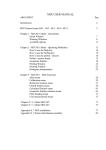
1
MANUALE DI ISTRUZIONI USO E MANUTENZIONE
INSTRUCTION HANDBOOK FOR USE AND MAINTENANCE
DIRASPATRICI ORIZZONTALI SEMICENTRIFUGHE
HORIZONTAL GRAPE STALK REMOVING MACHINES
“ZETA 20-30-20/A-30/A”
N° Matricola – Registration N°:
Anno di costruzione – Manufactoring year:
ATTENZIONE: Il presente manuale deve essere conservato in prossimità della macchina ed in luogo
conosciuto dal personale addetto alle operazioni di utilizzo, manutenzione e riparazione
La macchina a cui è allegato il presente libretto rispetta la direttiva CEE 89/392 e successive
modificazioni in materia di sicurezza e tutela della salute. Il marchio C E apposto sulla macchina e la
garanzia di conformità.
The machine, the handbook of which is enclosed herewith, is in line with the 89/392 EEC safety and
health protection regulations and following modifications.
The C E brand on the machine guarantees that it conforms with the above regulations.
La pigia-diraspatrice da Lei acquistata:
The machine you have purchased:
Modello/Model ________________
Anno/Year ____________________
è stata costruita interamente da:
has been entirely built by:
OMAC enosoluzioni s.r.l.
Via della Tecnologia, 12
62014 Corridonia (MC) Italy - Tel e fax +39 733 557386
www.officineomac.it [email protected]
Rivenditore autorizzato a cui rivolgersi
Authorized retailer
INTRODUZIONE / INTRODUCTION
Il presente libretto contiene le informazioni necessarie all’uso e alla manutenzione della Vostra
PIGIADIRASPATRICE ZETA 20-30-20/A-30/A.
Attenersi a tali disposizioni per ottenere il corretto ed ottimale funzionamento della macchina. La mancata
osservanza di queste avvertenze e/o l’eventuale manomissione della macchina solleverà la Ditta OMAC da
qualsiasi responsabilità per eventuali infortuni procurati da un uso improprio della stessa a persone o a cose.
Prima di mettere in funzione la macchina, è indispensabile che l’utilizzatore esegua tutte le operazioni
descritte nel presente libretto, e le applichi ogni volta durante l’uso o la manutenzione della macchina.
This handbook provides all the informations useful for use and maintenance of your DESTEMMER ZETA 2030-20/A-30/A.
If the instruction set forth in this hanbook are not followed, the manifacturer will not be liable for any futher
more, in the event of improper use of the machine, utilization that goes against specific national standards,
lack of required maintenance, unauthorized modifications or work, use of different or not original spare parts,
failure to follow the instructions.The manifacturer shall not be liable for any risks.The handbook cannot be
considered a reference in any modification that change the machine configuration are planned or made. In
this case, the manifacturer shall be liable for manifacturing defects only.
MANUALE DELL’UTENTE
INDICE
1. MOD. ZETA 20 - 30....................................................................................................................................... 2
2. MODELLO 20A - 30A ................................................................................................................................... 3
2. FUNZIONAMENTO / OPERATION............................................................................................................... 4
3. CARATTERISTICHE TECNICHE / TECHNICAL CARATHERISTICS ........................................................ 4
4. MISURE DI PREVENZIONE A CURA DELL’UTILIZZATORE / WARNINGS FOR THE USER ................. 5
5. USO PREVISTO E NON PREVISTO / USE OF THE MACHINES ............................................................... 5
6. TRASPORTO E PRIMA MESSA IN FUNZIONE / TRANSPORT AND STARTING UP .............................. 6
7. INSTALLAZIONE / INSTALLATION ............................................................................................................ 6
8. ISTRUZIONI D’USO / USE ........................................................................................................................... 6
9. RICERCA GUASTI / POSSIBLE CAUSES OF MALFUNCTION................................................................. 8
10. ISTRUZIONI PER LA MANUTENZIONE / MAINTENANCE ...................................................................... 8
11. INGOMBRI E PESI DELLA MACCHINA / DIMENSION AND WEIGHT OF THE MACHINES ................. 9
12. SCHEMA ELETTRICO MOTORE / ELECTRICAL DIAGRAM .................................................................. 9
1
1. MOD. ZETA 20 - 30
1. Cassonetto antinfortuni
Upper protective part
2. Tramoggia
Hopper
3. Motore elettrico
Electric motor
4. Pompa
Pump
5. Coclea alimentazione superiore
Upper feeding screw auger
6. Carter posteriore antinfortuni
Rear protection crankcase
7. Albero diraspatore
Destalking axle
8. Coclea alimentazione inferiore
Lower feeding screw auger
9. Cilindro forato
Sieve
10. Carter anteriore
Front crankcase
11. Sportello
Inspection door
I disegni delle Macchine hanno solo una funzione illustrativa ed indicativa della macchina e dei suoi componenti, non intende rappresentare proporzioni e
dimensioni reali.
Drawings of machines structure and components are only llustrative and indicative. They do not represent the real size and proportions of the machine.
2
2. MODELLO 20A - 30A
1. Cassonetto antinfortuni
Upper protective part
2. Tramoggia
Hopper
3. Motore elettrico
Electric motor
4. Pompa
Pump
5. Coclea alimentazione superiore
Upper feeding screw auger
6. Carter posteriore antinfortuni
Rear protection crankcase
7. Albero diraspatore
Destalking axle
8. Coclea alimentazione inferiore
Lower feeding screw auger
9. Cilindro forato
Sieve
10. Carter anteriore
Front crankcase
I disegni delle Macchine hanno solo una funzione illustrativa ed indicativa della macchina e dei suoi componenti, non intende rappresentare proporzioni e
dimensioni reali.
Drawings of machines structure and components are only llustrative and indicative. They do not represent the real size nd proportions of the machine.
3
2. FUNZIONAMENTO / Operation
L’albero diraspatore (7) le coclee di alimentazione (5) (8) e la pompa (4) girano proporzionalmente fra loro
tramite collegamenti a cinghia e a catena azionati da un motore elettrico (3).
I grappoli d’uva messi nella tramoggia (2) vengono trsportati dalla coclea (5) per caduta terminano all’interno
della macchina dove l’albero disparatore (7) provvede a diraspare.
I raspi vengono trascinati dal movimento di rotazione all’apposita bocca di uscita, gli acini aperti passando
attraverso il cilindro forato (9) cadono sopra l’altra coclea (8) che provvede a portarli nella pompa centrifuga
(4) per convogliarli a destinazione.
The destalking axle (7), the feeding screw auger (5) (8) and the pump (4) turn proportionally together by
means of connection bands or chains operated by an electrical engine (3). The bunches of grapes placed in
the hopper (2) are carried by the feeding screw until they fall inside the machine where they are destalked by
the destalking axle. Stalks are dragged to the exit opening by the rotating movement whereas grapes pass
through the sieve (9) an fall in the other feeding screw auger which carries them into the centrifugal pump.
3. CARATTERISTICHE TECNICHE / Technical caratheristics
MACCHINE MOD. ZETA
MACHINES MOD. ZETA
PRODUZIONE ORARIA Kg.
OUTPUT PER HOUR Kg.
PREVALENZA Mt.
HEAD Mt.
DIAMETRO CESTELLO mm.
DIAMETER CAGE mm.
POTENZA MOTORE HP.
ENGINE POWER HP.
VOLTAGGIO
VOLTAGE
FREQUENZA HZ
FREQUENCY HZ
POMPA ø DIAMETRO mm.
PUMP ø DIAMETER mm.
GRADO DI PROTEZIONE
PROTECTION
20
30
20/A
30/A
2000
3000
2000
3000
4
4
4
4
240/F
240/F
240/F
2,5
2,5
2,5
220-380
220-380
220-380
50
50
50
50
60
60
60
60
IP
IP
IP
IP
240/F
1,5
220-380
Rumore: Leq ponderato A 78.9÷83.8 db, (rilievi effettuati in ambiente esterno in condizioni di lavoro abituali,
in accordo con la metodica indicata in UNI 7712).
Noise: equivalent loudness level measured: 78.9÷83.8 dB. (Survey carried out outdoors in normal working
conditions according to the method indicated by UNI 7712).
F = Cestello fisso / Fixed Cage
Pigia-diraspatrici ZETA non superano il valore di 70 db (A) di livello di emissione di pressione sonora ponderato A.
4
4. MISURE DI PREVENZIONE A CURA DELL’UTILIZZATORE / Warnings for the user
-
L’utilizzatore non deve eseguire di propria iniziativa operazioni o interventi che non siano ammessi in
questo manuale.
Egli deve osservare rigorosamente le norme antinfortunistiche in vigore nel rispettivo paese.
Durante la riparazione o manutenzione della macchina, deve togliere la spina dalla presa e/o disinserire
l’interruttore, interrompendo così immissione di energia elettrica nella macchina. Ciò per evitare
l’avviamento accidentale che potrebbe causare danni a persone o a cose.
Durante il funzionamento, non deve muovere o spostare la macchina.
Prima di azionare la macchina deve accertarsi che il cavo e tutti i dispositivi elettrici siano efficienti.
Avviando la macchina deve evitare di avere le mani bagnate e/o essere a piedi nudi e/o nell’acqua.
Nell’operazione di diraspatura non deve utilizzare le mani o un qualsiasi utensile per spingere l’uva
attraverso le bocchette di caduta. Questa manovra è pericolosa per il rischio di abrasioni e di
trascinamento delle mani dell’ utilizzatore, qualora vengano a contatto con la coclea.
La macchina è stata progettata per avere una produzione media oraria che non può essere aumentata
spingendo più uva al suo interno; la coclea è perfettamente in grado di trasportare la quantità dell’uva
senza l’ausilio di mezzi esterni.
Per eliminare un accumulo eccessivo dei raspi sulla bocca di uscita usare un bastone lungo o un mezzo
con il manico lungo, non servirsi mai delle mani.
La macchina è stata progettata in modo tale che tutte le parti in movimento sono rese inoffensive tramite
l’uso di protezioni. La OMAC declina ogni responsabilità in caso di danni provocati dalla manomissione di tali
dispositivi.
-
The operator must follow all the operation written in this handbook
The operator must to observe strictly the current safety regulations of it’s own country
During washing, repairing or up keeping of the machine, make sure it is electrically isolated (remove plug
from the mains) to avoid damages to a persons or things
It is forbidden to move the machine while working
All electrical connections must be carried out by qualified persons.
The operator in charge of loading the machine must: wear tight-fitting clothes with cuffs adhering tightly
around the wrists, use cut resistant gloves when actually working, doing maintenance etc. use non slip
shoes, prevent children, animals or strangers from going near the working machine, not enter the space
inside the hopper while the machine is working. If necessary a suitable tool can be used but always
remaining with the body outside the working area.
The manufacturer declines all responsibility for injury to a persons or anomals caused by the non observance
of the instructions in this handbook.
5. USO PREVISTO E NON PREVISTO / Use of the machines
La pigiadiraspatrice ZETA 20-30-20/A-30/A sono state progettate e costruite esclusivamente per diraspare e
pigiare l’uva.
Sono utilizzabili inoltre per spingere il pigiato nella botte di fermentazione.
La macchina non è costruita in modo da avere utilizzazione diversa da quella sopra indicata, in particolare
non è adatta per trattare altri tipi di alimenti.
La ditta costruttrice, se non vengono rispettati i vincoli prescritti, non risponde di eventuali danni agli organi
meccanici ed elettrici della macchina e declina ogni responsabilità per eventuali infortuni procurati da un uso
non previsto della macchina.
The ZETA destemmers has been designed and built only for this purpose. This kind of machine allows the
decantino of must into the tank.
This machine cannot be used for purposes other than the ones it has been designed for and it is particularly
unsuitable for processing other types of food.
The company cannot be blamed for any mechanical or electrical damage of the machine or for any injury by
an inappropriate use of the same.
5
6. TRASPORTO E PRIMA MESSA IN FUNZIONE / Transport and starting up
Sollevamento con gru
Usare gru di portata sufficiente in base al peso della macchina indicato sulla targhetta.
Imbracare la macchina con cinghia passante sotto la tramoggia vicino al lato motore e verificare il
bilanciamento appena sollevata la macchina.
Fase preliminare prima dell’uso
Montare le protezioni antinfortunistiche come Fig. 1. Verificare che alla presa di alimentazione ci sia la
tensione prevista per il motore ed il conduttore di terra. Inserire il tubo di mandata del prodotto all’uscita della
pompa Fig. 2 a pagina 2.
Dichiarazione di conformità
Noi, OMAC di Leonardo Ceci, dichiariamo sotto la Ns. sola responsabilità che le nostre Macchine sono
conformi alla direttiva macchine 89/392 come modificata dalla direttiva CEE 91/368.
Lifting with cranes
The machine can be lifted with either a crane or a forkless lift truck by means of stripes (in observance of
current safety regulations).You must consider that the side with the motor will have a much grater weight.
Before using the machine
Open the box containing the upper safety part, than proceed to assemble all the parts (see drawing).
Make sure the mains is right to feed the motor.
Insert the half-pipe fitting in the tube, blocking it with a suitable hose clip on the outside. Then connect
everything to the pump by using the clamp provided.
Declaration of conformity
We certify under our sole responsibility that the our machines meets the legal requirements as directives
machines 89/392 as modified from directives 91/368 wants.
7. INSTALLAZIONE / Installation
-
Trasportare la macchina sollevandola con l’apposita maniglia.
Disporre la macchina nel luogo del funzionamento accertandosi che tutte e quattro le gambe posino
perfettamente al suolo.
Prima di iniziare la lavorazione passare acqua all’interno della macchina in movimento. Verificare che
alla presa di alimentazione ci sia la tensione prevista per il motore. Collegare il tubo di mandata del
prodotto all’uscita della pompa.
Installare il cassonetto antinfortuni (vedere disegno sottostante).
Move the machine by lifting it by the handle provided.
Put it down making sure that the four legs rest firmly on the ground.
Rinse the machine with water internally and externally to remove any
trace of dust then re-assemble the components making sure these is
perfectly sealed and blocked.
Install the upper protective part (see drawing).
8. ISTRUZIONI D’USO / Use
Dopo l’installazione e gli eventuali collegamenti con tubazioni, inserire la spina in un apposita presa e
premere l’interruttore principale per l’avviamento. Per le macchine con motore trifase controllare il senso di
rotazione.
ATTENZIONE: Prima dell’avviamento, l’utilizzatore deve assicurarsi che non ci siano impedimenti che
ostacolino il naturale movimento degli organi meccanici della macchina e soprattutto assicurarsi che
nessuno sia in prossimità degli organi che entrano in movimento; in particolare lo stesso utilizzatore o altre
persone presenti non devono avere mani, braccia o altre parti del corpo in prossimità della bocca, di uscita
raspi o all’interno del cassonetto. Ad avviamento avvenuto versare l’uva nella tramoggia appoggiando i
recipienti al bordo del cassonetto.
6
ATTENZIONE: Nell’operazione di diraspatura non utilizzare le mani o un qualsiasi utensile per spingere l’uva
attraverso la bocchetta di caduta. Questa manovra è pericolosa per il rischio di abrasioni e di trascinamento
delle mani dell’utilizzatore qualora vengano a contatto con la coclea. La macchina è stata progettata per
avere una produzione media oraria che non può essere aumenta spingendo più uva nel suo interno, la
coclea è perfettamente in grado di trasportare la giusta quantità d’uva senza l’ausilio di mezzi esterni.
Qualora si ritenesse necessario un intervento all’interno della tramoggia (intasamenti, corpi estranei)
spegnere la macchina e scollegare il cavo di alimentazione per prevenire avviamenti involontari. Per
eliminare un accumulo eccessivo di raspi alla bocca di uscita usare un attrezzo a manico lungo (rastrello,
pala), non servirsi mai delle mani.
Per tutti i casi che necessitano un arresto immediato della macchina è stato previsto che il pulsante d’arresto
sia del tipo “ad arresto rapido” o “d’emergenza”, è di colore rosso ed è situato sul motore elettrico a fianco
del tasto di avviamento (vedi schema “Quadro di comando”) Una volta premuto non consente l’avviamento
della macchina finché non viene sbloccato.
Per sbloccarlo girare il pulsante nel verso indicato dalla freccia disegnata sopra di esso.
Once the machines has been installed and any connection with pipes has been made, insert the plug in the
socket and turn on the machines by pressing the main switch. For three-phase motor machines, check that
the rotation corresponds to the one indicated on the machine.
IMPORTANT: before starting the machines, make sure that there is nothing obstructing the natural
movement of the machine’s electrical parts and above all, that no one is anywhere near the parts about to
move. The operator or anyone else present should particular keep hands; arms or other parts of the body
well away from the inside of the tank (Picture 3) and from the main opening where stalks are ejected from.
IMPORTANT: do not use neither hands nor any instrument to push the grapes towards the opening where
grapes fall through during the destalking operation as this would cause abrasions and result in the hands
being caught in the feeding screw. This machine has been designed to give an average hourly production
which cannot be increased by forcing more grapes into the machine. The feeding screw is perfectly capable
of carrying the correct amount of grapes without the help of any external instrument.
Should an intervention inside the hopper be necessary (e.: in case it becomes obstructed or something falls
into it), turn off the machine and disconnect the feeding cable to avoid the machine starting involuntarily. To
eliminate the excessive accumulation of stalks at the chute opening use an object with a long handle (either
a rake or a shovel). Never use hands.
Should it be necessary to stop the machines rapidly, press the red emergency button placed on the electric
engine next to the starting switch (see “Controls Panel” diagram Picture B). When the emergency button is
pressed the machine is blocked and will not start again until the button is released by turning the button in
the direction indicated by the arrow draw above it.
7
9. RICERCA GUASTI / Possible causes of malfunction
La macchina parte con difficoltà.
Controllare che la macchina sia alimentata da giusta tensione di rete. Non impiegare prolunghe di sezione
insufficiente che possono provocare cadute di tensione.
La pompa non riesce a spingere con sufficiente pressione.
Regolare la tensione delle cinghie di trasmisisone tramite l’apposito registro collocato alla base motore.
All’uscita dei raspi sono presenti anche alcuni acini.
Spegnere la macchina e pulire il cilindro forato (vaglio)
AVVERTENZE: La protezione (10) posta all’uscita dei raspi e il cassonetto (9) posto al di sopra della
tramoggia non limitano completamente l’accesso alle zone pericolose, sono un buon compromesso fra
necessità di protezione e le esigenze funzionali della macchina (la protezione (10) deve consentire un flusso
continuo di uscita dei raspi, il cassonetto (9) deve consentire che si possa scaricare senza troppo sforzo
l’uva della tramoggia, operazione effettuata di solito a mano).
L’azienda OMAC non è responsabile delle cause derivanti da eventuali modifiche apportate da terzi alle
macchine. L’azienda OMAC si riserva di apportare modifiche costruttive in qualsiasi momento senza obbligo
di comunicazione all’utente. Il presente libretto va conservato per futuri riferimenti.
The machine has difficulty in starting.
Check that the machine has an adequate input of tension from the network. Do not use extension leads with
an insufficient section which could cause a drop in tension.
The pump does not have enough pressure.
Regulate tension of transmission bands with the appropriate register placed at the base of the engine.
There are grapes among the stalks ejected by the machines.
Turn off the machine and clean the perforated cylinder (riddling).
NOTE: the protection provided at the opening where stalks are ejected (10) and the tank situated over the
hopper (9) do not completely limit access to the access to the dangerous parts of the machine. They are
however a good compromise between the need for protection and the machine’s functional requirements
(protection (9) must allow a continued outflow of stalks, the tank (9) must allow the grapes to be discharged
into the hopper without too much effort (this operation is usually carried out manually).OMAC cannot be held
responsible for any consequence deriving from any change on our machines made by a third party. OMAC
reserves itself the right to make any building changes at any time without having to inform the
use. Please keep this booklet for future reference.
10. ISTRUZIONI PER LA MANUTENZIONE / Maintenance
Dopo l’uso, a macchina spenta e con presa elettrica disinserita, si può procedere al lavaggio interno ed
esterno per asportare i residui della lavorazione.
Effettuare il lavaggio dopo ogni giornata di lavoro.
Per facilitare la pulizia, togliere lo sportello (nei modelli dove previsto) e/o estrarre il cestello forato.
ATTENZIONE: non effettuare alcun tipo di manutenzione con la macchina in movimento. La macchina può
essere smontata e riparata solo da tecnici specializzati.
Once the machine has been used and turned off and the plug has been disconnected, it is ready to be
washed internally and externally to remove any residue. The machine should be washed after each working
day. Once it has been disactivated, open the crankcase (20) and grease all chains and gear by applying
grease to allgreasing points, if any.
IMPORTANT: do not carry out any maintenance work while the machines is moving.
8
11. INGOMBRI E PESI DELLA MACCHINA / Dimension and weight of the machines
MACCHINA
MACHINE
lunghezza (cm.)
length (cm.)
larghezza (cm.)
width (cm.)
altezza (cm.)
height (cm.)
peso (kg.)
weight (kg.)
ZETA 20
110
65
85
80
ZETA 30
130
70
90
90
ZETA 20A
110
70
85
85
ZETA 30A
130
80
90
95
12. SCHEMA ELETTRICO MOTORE / Electrical diagram
K1
PA
PM
F1
CA
CM
M1
M2
M3
Teleruttore
Pulsante marcia
Pulsante arresto
Fusibile
Condensatore avviamento
Condensatore marcia
Morsetti
Il disegno della Macchina ha solo una funzione illustrativa ed indicativa della macchina e dei suoi componenti, non intende rappresentare proporzioni e
dimensioni reali.
Drawing of machine structure and components are only llustrative and indicative. They do not represent the real size nd proportions of the machine.
9