1
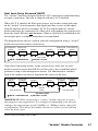
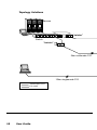
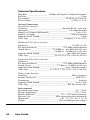
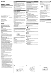
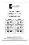
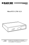
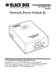
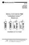
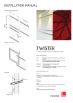
JULY 1999
LE612A-R4
LE612A-R5
LE611A-ST-R4
LE611A-ST-R5
LE615A-R4
LE615A-R5
LE611A-SMA-R4
LE611A-SC-R4
“twister”™
10MBPS MEDIA CONVERTERS
10BASE-2
10BASE-T
COL
AT
10BASE-FL
MM
RX
LK
10BASE-T
LK
TX
10BASE-FL
PWR
TX
SM
RX
AT
LK PWR
AT
10BASE-FL
LK PWR
AT
10BASE-T
LK
10BASE-T
LK
TX
SM
RX
AT
LK PWR
AT
AT
Installation & User Guide
CUSTOMER
SUPPORT
INFORMATION
Order toll-free in the U.S. 24 hours, 7 A.M. Monday to midnight Friday: 877-877-BBOX
FREE technical support, 24 hours a day, 7 days a week: Call 724-746-5500 or fax 724-746-0746
Mail order: Black Box Corporation, 1000 Park Drive, Lawrence, PA 15055-1018
Web site: www.blackbox.com • E-mail: [email protected]
© 1999 Black Box Corporation
All rights reserved.
Printed in USA.
Black Box and the Black Box logo are registered trademarks of Black Box Corporation.
All other trademarks appearing in this manual are the property of their owners.
This publication is protected by the copyright laws of the United States and other countries, with
all rights reserved. No part of this publication may be reproduced, stored in a retrieval system,
translated, transcribed, or transmitted, in any form, or by any means manual, electric, electronic,
electromagnetic, mechanical, chemical, optical or otherwise, without prior explicit written
permission of Black Box Corporation.
The information contained in this document is assumed to be correct and current. The
manufacturer is not responsible for errors or omissions and reserves the right to change
specifications at any time without notice.
Table of Contents
“twister” 10Mbps Media Converter Installation & User Guide
Introduction ............................................................................................... 4
Overview .................................................................................................... 5
Installation Guide ...................................................................................... 7
STEP 1: Unpacking the “twister” and Accessories .................... 7
STEP 2: Choosing an Appropriate Location .............................. 7
STEP 3: Setting the Switches ..................................................... 8
STEP 4: Connecting to the Network ........................................ 10
Twisted-pair .......................................................................... 10
Fiber Optic ............................................................................ 11
BNC ...................................................................................... 12
STEP 5: Applying Power ......................................................... 14
User Guide ............................................................................................... 16
System LEDs ............................................................................ 16
Link Loss Carry Forward (LLCF) ............................................ 17
Topology Solutions .................................................................. 18
Technical Specifications ........................................................... 20
Product Safety, EMC and Compliance Statements .................. 21
Introduction
Thank you for choosing “twister” media converters.
Media converters represent the hottest technology available for extending
Ethernet and Fast Ethernet networks. “twister” media conversion has
become a standard for providing a cost-effective means of integrating a
mixed media environment. As LANs grow and evolve, this technology
provides an ideal solution for building effective migration strategies.
These IEEE 802.3 compliant media converters are compatible with
Ethernet devices from other leading network technology providers. This
increases the flexibility of your network configuration by ensuring reliable
data transmission in multi-vendor as well as mixed media environments.
The information in this guide will help you to install and start using your
“twister” media converter.
4
Overview
The “twister” 10Mbps media converters provide seamless
integration of 10BASE-T Category 3, 4 and 5 twisted-pair with singlemode
and multimode 10BASE-FL fiber optic segments as well as thinnet coax in
Ethernet environments.
To optimize your Ethernet network, the media converter provides seamless
operation in half-duplex or full-duplex environments. Full signal restoration—
with a low bit delay — ensures accurate data transmission to and from LANs
within an organization. All signal activity is completely converted ensuring
accurate communication and collision detection in connected segments and
allowing maximum media length to be achieved on either side of the device.
The “twister” provides the following key features:
• A Link Loss Carry Forward (LLCF) enable/disable switch* is
included to provide an easy means for troubleshooting a
remote network connection. Refer to the section of this guide
titled Link Loss Carry Forward for more information.
•
All twisted-pair ports are equipped with an MDI-II to MDI-X
switch eliminating the need for crossover cables.
•
Auto polarity support on all twisted-pair ports.
Whether you are updating or expanding your existing network, the line of
“twister” media converters supports a wide range of configuration needs. The
“twister” includes the following media conversion combinations:
Universal Power Supply (90-250V)
LE612A-R4
RJ-45 to BNC
LE612A-R5
RJ-45 to BNC CABLE IN A BOX
LE611A-SC-R4 RJ-45 to FL multimode SC
LE611A-ST-R4
RJ-45 to FL multimode ST
LE611A-ST-R5
RJ-45 to FL multimode ST CABLE IN A BOX
LE615A-R4
RJ-45 to FL singlemode ST
LE615A-R5
RJ-45 to FL singlemode ST CABLE IN A BOX
LE611A-SMA-R4 RJ-45 to FL multimode SMA
*
Does not apply to the LE612A-R4, R5 (BNC).
“twister” Media Converter
5
6
Installation Guide
Follow the simple steps outlined in this section of the guide to install and
start using your “twister” media converter.
1
Unpack the “twister” and any accessories.
Check that the following components have been included with
your order:
• “twister” media converter
• Power Supply
• Power Cord
• Four (4) Rubber Feet
Your order has been provided with the safest possible packaging,
but shipping damage does occasionally occur. Inspect your order
carefully. If you discover any shipping damage, notify the carrier
and follow their instructions for damage and claims. Save the
original shipping carton in case return or storage of the unit is
necessary.
2
Choose an appropriate location.
The “twister” media converter is intended for use in either office
or industrial environments. The unit must be located within six (6)
feet of the AC power source being used and placed as far away as
possible from electrical noise generating equipment such as
copiers, electrostatic printers and other motorized equipment. If
exposed twisted-pair wiring is used nearby, the wiring should be
routed as far away as possible from power cords and data cables
to minimize interference.
The units may be oriented in any manner which permits the user
to make physical connection to the power supply and leaves a
minimum of six (6) inches of space for proper ventilation.
TUV Compliance Note. For pluggable equipment, the socket outlet
must be installed near the equipment and be easily accessible.
Bei Geräten mit Steckanschluß muß die Steckdose nahe dem Gerät
angebracht und leicht zugänglich sein.
“twister” Media Converter
7
3
Set the Switches.
Link Loss Carry Forward (LLCF) Switch.*
The media converter incorporates Link Loss Carry Forward
(LLCF) functionality as an aid in troubleshooting a remote
connection.
A switch for enabling/disabling LLCF is located on the rear
panel of the converter. When LLCF is enabled, the fiber optic
ports as well as the twisted-pair ports on the “twister” media
converter do not transmit a link signal until they receive a link
signal from the opposite port. Refer to the page titled Link Loss
Carry Forward in the User Guide section of this manual for
more detailed information.
The unit is shipped with the LLCF disabled. To re-set the LLCF,
simply slide the switch to the appropriate setting.
PWR
OFF
ON
LLCF
LLCF Switch
(default is OFF)
*
8
Does not apply to the LE612A-R4, R5 (BNC).
Installation Guide
DC INPUT/5VDC
MDI-II to MDI-X Switch.
All “twister” media converters with twisted-pair ports have an
MDI-II to MDI-X switch that eliminates the need for crossover
cables. This switch is located on the bottom of the unit directly
below the RJ-45 connector and allows simple setup in either
straight through or crossover configurations. Refer to the
illustration below.
10BASE-FL
10BASE-T
LK PWR
LK
TX TX
SM
SM
AT
RX RX
LK
AT
AT
AT
LK
MDI-II / MDI-X Switch
When setting the MDI-II to MDI-X switch, observe the
positioning of the following symbols:
• the parallel symbol (II) indicates a straight through or
parallel connection.
• the cross symbol (X) indicates a crossover connection.
These symbols are clearly marked on the bottom of the unit.
Using a pointed object, simply slide the switch in the direction
of the appropriate symbol. Use the following table as a guide:
A device that is wired straight through, needs one crossover connection:
If the cable is…
… the MDI-II to MDI-X Switch Setting should be
straight through
crossover
X
II
A device that is wired crossover, needs a parallel connection:
If the cable is…
… the MDI-II to MDI-X Switch Setting should be
straight through
II
crossover
X
“twister” Media Converter
9
4
Connect to the network.
The “twister” media converter offers the ease of plug-and-play
installation. Please refer to the appropriate section below for
more information and guidelines regarding specific network
connections.
Twisted-pair Connections (all models).
The “twister” provides one shielded RJ-45 connector for
Category 3, 4 or 5 twisted-pair segments and supports a
maximum link length of 100 meters.
NOTE: Be sure you have set the MDI-II to MDI-X switch
located on the bottom of the unit to the proper configuration.
Refer back to STEP 3 if necessary.
Once power is applied to the unit, correct connectivity can be
verified via the LK (link) LED.
10BASE-FL
10BASE-T
LK
TX
SM
RX
LK PWR
AT
10BASE-FL
10BASE-T
LK
TX
10
Installation Guide
SM
RX
AT
LK PWR
AT
AT
Fiber Optic Connections
These “twister” models support 10BASE-FL segments via ST,
SMA or SC connectors:
• the LE611A-SC-R4 provides one set of FL multimode SC
connectors and support a maximum segment length of up
to 2km for remote links.
• the LE611A-ST-R4, -R5 provides one set of FL multimode ST
connectors and support a maximum segment length of up
to 2km for remote links.
• the LE615A-R4, -R5 provides one set of FL singlemode ST
connectors and support a maximum segment length of up
to 15km for remote links.
• the LE611A-SMA-R4 provides one set of FL multimode SMA
connectors and support a maximum segment length of up
to 2km for remote links.
10BASE-FL
10BASE-T
LK
TX
SM
RX
LK PWR
AT
10BASE-FL
10BASE-T
LK
TX
SM
RX
AT
LK PWR
AT
AT
“twister” Media Converter
11
When making fiber optic connections, be sure that the transmit
(TX) port of the “twister” connects to the receive (RX) port of
the connected device; and be sure that the transmit (TX) port of
the connected device connects to the receive (RX) port of the
“twister” unit.
Once power is applied to the unit, correct connectivity can be
verified via the LK (Link) LED.
BNC Connections
The LE612A-R4, -R5 attaches to thinnet coaxial cable via a
standard BNC connector and supports a maximum segment
length of 185 meters. The unit is shipped from the factory with
the termination disabled. Use the unit in a daisy-chain configuration or use a T-connector for proper termination.
10BASE-2
10BASE-T
COL
PWR
AT
12
Installation Guide
LK
IMPORTANT: The coaxial cable of a LAN must be properly
terminated at each end regardless of the device used at the end
of each cable. A BNC terminator must be attached to each end
of each trunk segment. One of the two terminators on each
segment must be grounded. Refer to the illustration below:
SEGMENT 1 (0.5 meters min. / 185 meters max.)
Workstation
Grounded BNC Terminator
Workstation
Repeater
Workstation
“TWISTER”
Ground Wire
BNC T-Connector
UTP Cable
up to 100 meters
Wall Outlet
BNC Terminator
Wall Outlet
Ground Wire
Grounded BNC Terminator
“twister”
Workstation
Workstation
Workstation
Workstation
Workstation
SEGMENT 2 (0.5 meters min. / 185 meters max.)
“twister” Media Converter
13
5
Apply power.
Power is provided to the “twister” unit from the desktop power
supply module. This power module is equipped with a S760
hollow-type plug for insertion into the DC jack located on the
back of the “twister” unit and standard IEC 320-type AC power
receptacle.
When making power connections, it is recommended that the
DC power cord be connected to the DC input jack located on the
back of the “twister” media converter before making the AC
connection to the outlet. Be sure to seat the power cord into the
strain relief clip to ensure against accidental disconnection.
Strain Relief Clip
PWR
OFF
ON
LLCF
14
Installation Guide
DC INPUT/5VDC
Upon receiving power, the “twister” media converter goes into
normal operation mode and automatically provides the appropriate signal translation between the connected network segments.
Be sure to verify correct segment connectivity via the LK (link)
LEDs on the front of the unit.
If an additional extension cord is used to connect the power
module to the power source, the following guidelines must be
followed:
While one end of the AC power cord can be fitted with
whatever plug is standard for the country of operation, the
end that connects to the “twister” power supply module
must have a female plug that fits this type of AC receptacle.
• AC 115V (North American): use a UL-listed and CSAcertified cord set consisting of a minimum 18 AWG, type
SVT or SJT three-conductor cord, a maximum of 15 feet in
length and a parallel blade, grounding-type attachment
plug rated 15A, 125V.
• AC 230V (USA): use a UL-listed cord set consisting of a
minimum No. 18 AWG, type SVT three-conductor cord,
a maximum of 15 feet in length and a Tandem blade
grounding-type attachment plug rated 15A, 250V.
• 240V (outside USA): use a cord set consisting of a
minimum No. 18 AWG cord and grounding-type
attachment plug rated 15A, 250V. The cord set should
have the appropriate safety approvals for the country in
which the “twister” is installed and should be marked
HAR.
“twister” Media Converter
15
User Guide
This section contains more detailed user information regarding certain
operating features for your “twister” Media Converter.
System LEDs
The “twister” media converter provides LEDs for the visible
verification of unit status and proper functionality as well as aiding in
troubleshooting and overall network diagnosis and management.
LEDs indicate the following:
• PWR (power): the unit is ON and functioning in normal
operation mode.
• LK: (link; twisted-pair and fiber optic ports): satisfactory link
status on the respective port.
• AT (activity): the port is receiving data.
• COL* (collision): detection of a collision condition and
subsequent JAM packets generated on both segments.
Once power is applied to the unit, correct connectivity can be verified via
the LK LED.
*
16
Applies to the LE612A-R4, R5 (BNC) only.
User Guide
Link Loss Carry Forward (LLCF)*
The “twister” has been designed with an LLCF function for troubleshooting
a remote connection. The unit is shipped with the LLCF disabled.
When LLCF is enabled, the fiber optic ports as well as the twisted-pair ports
on the “twister” do not transmit a link signal until they receive a link signal
from the opposite port. For example, if LLCF is enabled and two “twister”
media converters are connected via a fiber cable with nothing else connected to
them, the Link LED does not illuminate. When a valid link is established at the
twisted-pair port, a complete connection is accomplished.
The diagram below shows a typical network configuration using a “twister”
media converter for remote connectivity:
Management
Station
Switch/Hub
w/SNMP
LED lit = established link
“twister”
“twister”
Switch/Hub Management
w/SNMP
Station
Remote
up to 15km
LED unlit = no link
If the fiber connection breaks, or the remote device fails, the “twister”
media converter carries that link loss all the way to the switch/hub which
generates a trap to the management station. The administrator can then
look at the media converter to determine the source of the loss.
Management
Station
Switch/Hub
w/SNMP
“twister”
Broken
Remote
Cable
Trap generated
LED lit = established link
“twister”
Switch/Hub Management
w/SNMP
Station
Trap generated
Link Loss Carried
LED unlit = no link
IMPORTANT: When connecting a “twister” media converter to a port
that supports auto-negotiation, it is strongly recommended to fix the port
setting to the appropriate speed (100Mbps or 10Mbps) and to either full
or half-duplex. This allows the media converter to sense receive link and
select the active port.
*
Does not apply to the LE612A-R4, R5 (BNC).
“twister” Media Converter
17
Topology Solutions
Servers
“twister”
Switch
“twister”
2km multimode F/O
15km singlemode F/O
Twisted-pair Links
F/O Links
18
User Guide
Enterprise Switch
“twister”
Enterprise
2km multimode F/O
Switch
“twister”
“twister” Media Converter
19
Technical Specifications
Data Rate _________________ 10Mbps half-duplex; 20Mbps full-duplex
Bit Delay _____________________________________________ < 5 bits
Power Input ______________________________ 90-260V AC 50/60 Hz
Power Output __________________________________ +5VDC @ 1.2 A
Network Connections
Twisted-Pair Interface
Connector _____________________________ Shielded RJ-45, 8-pin jack
Impedance ___________________________________ 100 Ohms nominal
Signal Level Output (differential) _______________________ 2.0 to 2.8V
Signal Level Input _____________________________ 350mV minimum
Supported Link Length ____________________________________ 100m
Cable Type ______________________________ Category 3, 4, or 5 UTP
Multimode Fiber Optic Interface
Connector ______________________________________ ST, SMA or SC
RX Input Sensitivity _____________________ -32.5 dBm peak minimum
Output Power _________________ -21.8 dBm to -16.8 dBm (50/125 µm)
______________________ -19 dBm to -14 dBm (62.5/125 µm)
Supported Link Length _______________________ up to 2km full duplex
Cable Type ______________________ 50/125, 62.5/125, 100/140 µm F/O
Singlemode Fiber Optic Interface
Connector ________________________________________________ ST
RX Input Sensitivity _____________________ -32.5 dBm peak minimum
Output Power _____________________ -17 dBm to -23 dBm (9/125 µm)
Supported Link Length ______________________ up to 15km full duplex
Cable Type __________________ 8.3/125, 8.7/125, 9/125, 10/125 µm F/O
Thinnet Coax Interface
Connector ______________________________________ BNC receptacle
Internal Transceiver _________________________________ IEEE 802.3
Termination ___________________________________________ disabled
Supported Link Length _______________________________ up to 185m
Cable Type _________________________________ RG-58 coaxial cable
Environmental
Operating Temperature _______________________________ 0° — 55° C
Storage Temperature ________________________________ -25° —70° C
Relative Humidity _____________________ 5% — 95% non-condensing
Physical Case _____________________ Fully enclosed metal construction
Dimensions ___________________________ 4.83” L x 3.26” W x 1.71” H
Weight
__________________________ 3 lbs (including power supply)
20
User Guide
Product Safety, EMC and Compliance Statements
This equipment complies with the following requirements:
• UL
• CSA
• EN60950 (safety)
• FCC Part 15, Class A
• EN55022 Class A (emissions)
• EN50082-1 (immunity)
• IEEE 802.3
• IEC 825-1 Classification
Class 1 Laser Product
Radio Frequency Interference Statement
FCC Radio Frequency Interference Statement
This equipment has been tested and found to comply with the limits for a
Class A digital device, pursuant to Part 15 of the FCC Rules. These limits are
designed to provide reasonable protection against harmful interference when
the equipment is operated in a commercial environment. This equipment
generates, uses and can radiate radio frequency energy, and if not installed
and used in accordance with the instruction manual, may cause harmful
interference to radio communications. Operation of this equipment in a
residential area is likely to cause harmful interference in which case the user
will be required to correct the interference at his own expense.
Caution: Changes or modifications to this equipment not expressly
approved by the party responsible for compliance could void the user’s
authority to operate the equipment.
Canadian Radio Frequency Interference Statement
This Class A digital apparatus meets all requirements of the Canadian
Interference-Causing Equipment Regulations.
Cet appareil numérique de la classe A respecte toutes les exigences du
Règlement sur le matériel brouilleur du Canada.
“twister” Media Converter
21
Electrical Safety Statement
Normas Oficiales Mexicanas (NOM)
INSTRUCCIONES DE SEGURIDAD
1. Todas las instrucciones de seguridad y operación deberán ser leídas antes
de que el aparato eléctrico sea operado.
2. Las instrucciones de seguridad y operación deberán ser guardadas para
referencia futura.
3. Todas las advertencias en el aparato eléctrico y en sus instrucciones de
operación deben ser respetadas.
4. Todas las instrucciones de operación y uso deben ser seguidas.
5. El aparato eléctrico no deberá ser usado cerca del agua—por ejemplo,
cerca de la tina de baño, lavabo, sótano mojado o cerca de una alberca, etc.
6. El aparato eléctrico debe ser usado únicamente con carritos o pedestales
que sean recomendados por el fabricante.
7. El aparato eléctrico debe ser montado a la pared o al techo sólo como sea
recomendado por el fabricante.
8. Servicio—El usuario no debe intentar dar servicio al equipo eléctrico
más allá a lo descrito en las instrucciones de operación. Todo otro
servicio deberá ser referido a personal de servicio calificado.
9. El aparato eléctrico debe ser situado de tal manera que su posición no
interfiera su uso. La colocación del aparato eléctrico sobre una cama,
sofá, alfombra o superficie similar puede bloquea la ventilación, no se
debe colocar en libreros o gabinetes que impidan el flujo de aire por
los orificios de ventilación.
10. El equipo eléctrico deber ser situado fuera del alcance de fuentes de calor
como radiadores, registros de calor, estufas u otros aparatos (incluyendo
amplificadores) que producen calor.
22
User Guide
11. El aparato eléctrico deberá ser connectado a una fuente de poder sólo
del tipo descrito en el instructivo de operación, o como se indique en
el aparato.
12. Precaución debe ser tomada de tal manera que la tierra fisica y la
polarización del equipo no sea eliminada.
13. Los cables de la fuente de poder deben ser guiados de tal manera que
no sean pisados ni pellizcados por objetos colocados sobre o contra
ellos, poniendo particular atención a los contactos y receptáculos donde
salen del aparato.
14. El equipo eléctrico debe ser limpiado únicamente de acuerdo a las
recomendaciones del fabricante.
15. En caso de existir, una antena externa deberá ser localizada lejos de las
lineas de energia.
16. El cable de corriente deberá ser desconectado del cuando el equipo no
sea usado por un largo periodo de tiempo.
17. Cuidado debe ser tomado de tal manera que objectos liquidos no sean
derramados sobre la cubierta u orificios de ventilación.
18. Servicio por personal calificado deberá ser provisto cuando:
A: El cable de poder o el contacto ha sido dañado; u
B: Objectos han caído o líquido ha sido derramado dentro del aparato; o
C: El aparato ha sido expuesto a la lluvia; o
D: El aparato parece no operar normalmente o muestra un cambio en su
desempeño; o
E: El aparato ha sido tirado o su cubierta ha sido dañada.
“twister” Media Converter
23
© Copyright 1999. Black Box Corporation. All rights reserved.
1000 Park Drive • Lawrence, PA 15055-1018 • 724-746-5500 • Fax 724-746-0746
5660-211112-002 A
7/99