1
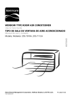
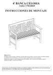
Operator's Manual
Grass Bag Kit
for the 36-inch Wide Cut Mower
Part No. 333170
For answers to your questions
about this product, call:
CAUTION: Before using
this product, read this
manual and follow all
1-800-659-5917
Sears Craftsman
Help Line
5 a.m. - 5 p.m., Mon - Sat
Safety Rules and
Operating Instructions.
Sears, Roebuck and Co., Hoffman
Estates, IL 60179, U.S.A.
Visit our Sears website: www.sears.com/craftsman
Printed in U.S.A.
FORM NO. 02005609 Rev 09_0
(10/2009)
Assembly
andOperation
EspaSol
ServiceNumbers
2
8
BackCover
WARNING:
Before installing this accessory, shut the engine off and allow it to cool. Disconnect the
spark plug wire from the spark plug. Refer to the mower's Operator's Manual for complete safety
instructions. Do not operate the mower without the entire grass bag in place. Turn the mower off and
disconnect the spark plug before emptying the grass bag.
CARTONCONTENTS
Before installing this accessory, remove all parts from the carton. Use caution when handling parts, some metal
parts may have sharp edges. Carton contents, including items included within the hardware pack, are shown in
Figures 1 and 2 on page 3. Part numbers are shown in parentheses and each item has been identified with a letter
code, [X], for use when following the assembly instructions. Reference to right or left side of the mower is observed
from the operating position.
TOOLSREQUIRED
Two 9/16" wrenches. Two 7/16" wrenches. One 3/8" wrench. One Flat Blade and One Phillips screwdriver.
[E]RightLatch
(703-06694)
[D]LeftLatch [F]BackingPlate
(703-06695) (703-06692)
•
ii
[G] Cute Mounting Bracket
(703-06693)
[S] Chute Baffle
(02005727)
[C]Handles
(703-06696)
[B]BagFrame
(01003986)
/
[A] Struts
[H] Cloth Bag
(01003221)
Figure 1
Chute Bracket to
Handle Hardware
Chute Baffle
to Mower
Backing Plate
[K] 1/4-20 x 1.00
Qty. 4
(01000944)
[P] 3/8-16 X 1.00 ......._-r:
Qty. 2
(00012171)
[I] Internal Tooth.
Washers Qty. 4
(02005631)
/
[Q] 3/8 Flat -_DP'L,,
Washers Qty. 4
(01000723)
[L] 1/4-20 Nylock
......
nuts Qty. 4
__)
00012152)
[N] 10-32 Nylock-''l_
nuts Qty. 4
(00014608)
Figure 2
_
_ j
(f %
';
_-j/i
,
'\
Latch Hardware
M] 10-32 x 5/8_
Pan Head Screws
Qty. 4 (00030906)
[T] 5/16-18 X "-'----tb_
1.00 Qty. 1
(00013092)
-[j
x j
/
.J
[R] 3/8-16 Nylock
nuts Qty. 2
(00012173)
Chute Bracket
to Mower
[0] 3/8-16 X 1.25_
Qty. 2 (00011444)
[R] 3/8-16 Nylock
nuts Qty. 2
(00012173)
[U] 5/16 Flat
Washers Qty. 1
(00012169)
[V] 5/16-18 Nylock
nuts Qty. 1
(00012165)
[J] 1/4-20 x 5/8
Screws Qty. 2
(02005630)
_-Z_
i
....
li....
[I] Washers _
Qty. 2
(02005631)
_'&
Struts
ASSEMBLY
INSTRUCTIONS
1.
2.
Remove Bag Frame [B] from Backing Plate [F].
Using (2) 1/4-20 x 5/8 Pan Head Screws [J] and 2
Internal Tooth Washers [I], attach two Struts [A] into
frame as shown below in Figure 3.
Struts.
Bolt
Handle
Internal Tooth
Washer
Hole
Figure 5
,
Install Chute Mounting Bracket [G] to Backing Plate
[F] using (2) 3/8-16 x 1.00 bolts [P], (4) 3/8 Flat
Washers [Q] and (2) 3/8-16 Nylock nuts [R] as
shown below in Figure 6.
Figure 3
,
Install the Cloth Bag [H] to Bag Frame [B]. Attach
the "J" strip of the bag to the frame using a flatblade
screwdriver to pry the strip as shown below in
Figure 4.
Backing Plate
Chute Mounting Bracket
Figure 6
"J" Strip
Flatblade Screwdriver
Figure 4
,
IMPORTANT: The two bolts and two washers go J
through Chute Mounting Bracket and Backing
J
Plate. Secure but do not tighten at this stage of
assemb y.
Attach two handles [C] to Bag Frame assembly [B]
with four 1/4-20 x 1.00 capscrews [K], four Internal
Tooth Washers [I] and four 1/4-20 Nylock nuts [L].
Insert capscrew through washer and through hole in
handle and through bag (bag must be cut to insert
bolt). Tighten nuts as shown in Figure 5.
,
Attach Left [D] and Right Latch [E] to Backing Plate
[F] with four 10-32 x 5/8 Panhead Screws [M], and
four 10-32 Nylock nuts [N]. As shown in Figure 7 on
the next page.
,
PanHead
Screw
Attach Chute Baffle [S] and chute baffle previously
removed in step 8 to the inside of the mower deck
using (1) 5/16-18 x 1.00 bolt [T], (1) 5/16 Flat
Washer, and (1) 5/16-18 Nylock nut.
See Figure 9 below.
RightLatch
Nut
Bolt
Nut
Figure 7
Washer
I IMPORTANT:
Do not
nutsfreely.
completely, as I
Latches must slide
up tighten
and down
7.
Remove Chute Deflector from the mower deck by
removing (2) 3/8-16 nuts from the chute bracket
and save for future usage.
Chute Baffle
Chute Baffle
Figure 9
without the grass collector installed. If the
grass
collector
removed
the chute
DANGER:
Do kit
notisoperate
mower
deflector must be installed.
[_k,
8.
10. Using (2) 3/8-16 x 1.25 bolts [0] and (2) 3/8-16
Nylock nuts [R], attach backing plate [F] to the unit
as shown below in Figure 10.
Remove chute baffle from the mower deck. This
part will be reinstalled in the next step with the new
baffle and hardware provided. See Figure 8.
Chute
Mounting
Bracket
Nut
Bolt
Washer
_
e_
Chute Baffl
Bolt
Nut
Figure 10
Figure 8
5
11. AdjustBackingPlate[F]sothatit isflushagainst
frontpartandtoppartofchuteopeningasshown
belowinFigure11andtightennutsonChute
Mounting
Bracket[G].
BackingPlate
topedgeof
chuteopening
frontedgeof
chuteopening
Figure11
12. AttachBagFrame[B]to BackingPlate[F]as
shownbelowinFigure12.
BagFrame
BackingPlate
Figure 12
6
OPERATION
1.
2.
3.
4.
Turn the mower off and disconnect the spark plug
wire before emptying the grass bag.
Empty the bag when 3/4 full. To remove the grass
bag, lift up on the right and left latches to release
the top part of the grass bag. Then using the
handles, tilt the catcher assembly toward you and
lift up. This releases the lower portion of the Bag
Frame from the Backing Plate see Figure 10 on
page 6.
Empty bag and dispose of clippings properly.
Refer to local regulations..
Reattach the Bag Frame by aligning the pins in
the bottom of the Bag Frame into the holes in the
lower part of the Backing Plate. Then put the top
part into the Left and Right Latches.
without the grass collector installed. IfI
the
grass collector
is removed
the II
DANGER:
Do notkit operate
mower
chute deflector must be installed.
I
Montaje y funcionamiento
Nt_mero de servicio
8
Cubierta posterior
ADVERTENClA:
Antes de instalar este accesorio, apague el motor y deje que se enfr[e.
Desconecte el cable de la bujia. Lea el Manual del 'Operador de la 'cortadora de cesped para conocer
todas las instrucciones de seguridad. No opere la cortadora de cesped si la bolsa de recolecci6n no
esta.completamente en su lugar. Apague la cortadora de cesped y desconecte la bujia antes de vaciar
la bolsa de recolecci6n.
CONTENIDO
DELACAJA
Antes de instalar este accesorio, saque todas las piezas de la caja. ManipWelas con cuidado, algunas piezas
meta.licas tienen bordes filosos. El contenido de la caja, incluidos los articulos dentro del paquete de elementos de
ferreter[a, se muestra en las Figuras 1 y 2 en la pa.gina 3. Los nt_meros de las piezas aparecen entre parentesis y
cada elemento ha sido identificado con un c6digo de letra, [X], que debe usarse para seguir las instrucciones de
montaje. Las referencias a los lados derecho o izquierdo de la cortadora de cesped se hacen observando la
ma.quina desde la posici6n de operaci6n.
HERRAMIENTAS
NECESARIAS
Dos Ilaves 9/16". Dos"llaves 7/16. Una"llave 3/8. Un destornillador paleta plana y otro cabeza Phillips.
[D] Sujetador
izquierdo
(703-06695)
[F] Contraplato
(703-06692)
[E] Sujetador
derecho
[B] Marco de la
bolsa
(703-06694)
(01003986)
[C] Manijas
(703-06696)
r
÷
[G] Soporte de montaje del canal
(703-06693)
[S] Clavija del canal
(02005727)
/
[A] Puntales
[H] Bolsa de tela
(01003221)
Figura 1
Pieza metalicas a manipular
[K] 1/4-20 x 1.00.
Cantidad: 4
01000944)
iJ _
L
--
-
[I] Arandela
dentada interna.
Cantidad: 4
(02005631)
[L] Tuercas de
seguridad Nylock 1/_£_
4-20. Cantidad: 4
'00012152)
.....
M] Tornillo de
cabeza completa
10-32 x 5/8.
Cantidad: 4
[P] 3/8-16 x 1.00.
Cantidad: 2
(00012171)
[T] 5/16-18 x
1.00. Cantidad: 1"""1_
/ooo13o92t
\
planas 3/8.
Cantidad: 4
(01000723)
J
[U] Arandelas
planas 5/16.
Cantidad: 1
(00012169)
[V] Tuercas de
seguridad Nylock 5/
16-18. Cantidad: 1
(00012165)
[R] Tuercas de
Piezas metalicas para sujetar
Soporte de canal a
cortadora
Soporte de canal a
contraplato
3/8-16. Cantidad:
segu
ridad Nyl°ck 2"_,_
(00012173)
Soporte de canal a
cortadora
[J] Tornillos 1/420 x 5/8.
Cantidad: 2
(02005630)
(00030906)
[O] 3/8-16 x 1.25.
Cantidad: 2
(00011444)
_
[N] Tuercas de
seguridad Nylock
10-32. Cantidad: 4
00014608)
JR] Tuercas de
seguridad Nylock
[I] Arandelas.
Cantidad: 2
3 8_oaot,dad:
6.
(02005631)
Figura 2
(00012173)
J-_-i_
_
ii
Puntales
INSTRUCCIONES
DEMONTAJE
1.
2.
Extraiga el marco de la bolsa [B] del contraplato [F].
Usando (2) tornillos de cabeza completa 1/4-20 x 5/8 [J] y
(2) arandelas dentadas internas [I], fije dos puntales [A] al
marco, segQn se muestra a continuaci6n en la figura 3.
Puntales
Perno
Manija
Arandela
dentada interna
Orificio
Figura 5
5,
Instale el soporte de montaje del canal [G] en el
contraplato [F] usando (2) pernos 3/8-16 x 1.00 [P], (49
arandelas planas 3/8 [Q] y (2) tuercas de seguridad
Nylock 3/8-16 [R] segt]n se muestra en la Figura 6.
Figura 3
3,
Instale la bolsa de tela [H] en el marco de la bolsa [B]. Fije
la franja de la bolsa "J" al marco con un destornillador de
paleta plana a fin de hacer palanca en la franja como se
muestra a continuaci6n en la Figura 4.
Contraplato
Soporte d
canal
tje del
Figura 6
"J" Franja
Destornillador
IMPORTANTE: Los dos pernos y las dos arandelas
van a traves del soporte de montaje del canal y
contraplato. Asegurelos, pero no los ajuste en este
paso del montaje.
de paleta plana
Figura 4
4,
6,
Fije dos manijas [C] al montaje del marco de la bolsa [B]
con cuatro tornillos de cabeza 1/4-20 x 1.00 [K], cuatro
arandelas internas dentadas [I] y cuatro tuercas de
seguridad Nylock 1/4-20 [L]. Inserte los tornillos en las
arandelas a trav_s de la manija y la bolsa (la bolsa debe
estar cortada para insertar el perno). Ajuste las tuercas
segQn se muestra en la Figura 5.
10
Fije el sujetador izquierdo [D] y derecho [E] al contraplato
[F] con cuatro tornillos de cabeza completa 10-32 x 5/8
[M] y cuatro tuercas de seguridad Nylock 10-32 [N]. Como
se muestra en la Figura 7 en la siguiente pagina.
9,
Tornillo
cabeza
completa
Fije el soporte del canal [S] y el soporte del canal
anteriormente extraido en el paso 8 a la parte interna de
la plataforma de la cortadora usando (1) perno 5/16-18 x
1.00 [T], (1) arandela plana 5/16 y (1) tuerca de
seguridad Nylock 5/16-18.
Vea la Figura 9 a continuaci6n.
Sujetador
derecho
\
Tuerca
Figura 7
Perno
IMPORTANTE: No ajuste completamente las
tuercas, ya que los sujetadores deben deslizarse
libremente hacia arriba y abajo.
7.
Extraiga el deflector del canal de la plataforma de la
cortadora sacando las (2) tuercas 3/8-16 del soporte del
canal y guardelas para uso futuro.
Soporte de canal
Soporte de canal
Figura 9
sin tener el colector de cesped instalado.
Si ELIGRO:
el kit colector
cesped
se extrae,
debe
No de
haga
funcionar
la unidad
instalarse el deflector del canal.
[_
8,
Arandela
10. Usando (2) pernos 3/8-16 x 1.25 O] y (2) tuercas de
seguridad Nylock 3/8-16 [R], fije el contraplato [F] a la
unidad como se muestra a continuaci6n en la Figura 10.
Extraiga el soporte del canal desde la plataforma de la
cortadora. Esta pieza se volvera a colocar en el pr6ximo
paso con la nueva clavija y piezas metalicas
suministradas. Vea la Figura 8.
Soporte
de
montaje
del canal
Tuerca
Perno
Ara
Soporte de
Perno
Tuerca
Figura 10
Figura 8
11
Ajuste el contraplato [F] de manera que quede al ras con
la parte superior frontal de la abertura del canal como se
muestra en la figura 11 y ajuste las tuercas en el soporte
de montaje del canal [G].
1,
Contraplato
borde superior
de la abertura
del canal
Figura
2.
borde frontal de
la abertura del
canal
11
Fije el marco de la bolsa [B] al contraplato [F] como se
muestra a continuaci6n en la Figura 12.
Marco de la bolsa
Contraplato
Figura 12
12
OPERAClON
1.
2.
3.
4.
Apague la cortadora de cesped y desconecte
el
cable de la bujia antes de vaciar la bolsa de
recolecci6n.
Vacie la bolsa cuando se Ilene 3/4 de la misma. Para
quitar el c_sped de la bolsa, levante los sujetadores
derecho e izquierdo para liberar la parte superior de la
bolsa para c_sped. Luego, con la ayuda de las
manijas, incline el conjunto del recolector de c_sped
hacia usted y levante. Esto libera la parte mas inferior
del marco de la bolsa del contraplato. Ver Figura 10 en
la pagina 6.
Vacie la bolsa y deseche adecuadamente los recortes.
Consulte las reglamentaciones locales.
Fije nuevamente el marco de la bolsa alineando los
pasadores en la base del marco de la bolsa en los
orificios en la parte inferior del contraplato. A
continuaci6n, coloque la parte superior en los
sujetadores izquierdo y derecho.
PELIGRO:
No haga funcionar
la unidad
sin tenet el colector de c_sped instalado.
Si el kit colector
de c_sped
se extrae
debe instalarse
el deflector del canal.
13
This page intentionally
14
left blank.
This page intentionally
15
left blank.
Your Home
For expert troubleshooting
and home solutions advice:
www.managemyhome.com
For repair - in your home - of all major brand appliances,
lawn and garden equipment, or heating and cooling systems,
no matter who made it, no matter who sold it!
For the replacement parts, accessories and
owner's manuals that you need to do-it-yourself.
For Sears professional installation of home appliances
and items like garage door openers and water heaters.
1-800-4-MY-HOME
Call anytime,
®
(1-800-469-4663)
day or night (U.S.A. and Canada)
www.sears.com
www.sears.ca
Our Home
For repair of carry-in items like vacuums, lawn equipment,
and electronics, call anytime for the location of your nearest
Sears Parts & Repair Service Center
1-800-488-1222
(U.S.A.)
1-800-469-4663
www.sears.com
To purchase a protection agreement
1-800-827-6655
on a product serviced
by Sears:
1-800-361-6665
(Canada)
Au Canada pour service
en fran(_ais:
(U.S.A.)
Para pedir servicio de reparaci6n
a domicilio, y para ordenar piezas:
1-888-SU-HOGAR
1-800-LE-FOYER
®
Trademark
/
TM
Trademark
/ SM Service
Mc
(1-800-533-6937)
www.sears.ca
(1-888-784-6427)
® Registered
(Canada)
www.sears.ca
Mark of Sears Brands,
® Marca Registrada / rM Marca de Fabrica / SM Marca de Servicio
MC Marque de commerce / MD Marque d6posee de Sears Brands,
LLC
de Sears Brands,
LLC
LLC
© Sears Brands,
LLC