1
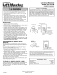
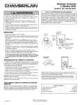
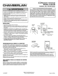
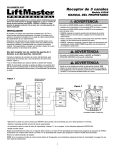
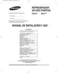
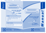
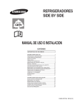
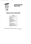
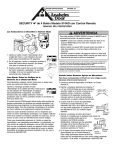
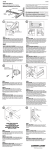
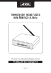
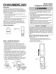
Universal Radio Control
OWNERS MANUAL
WARNING
Model 535-315LM SECURITY✚ Receiver Only
WARNING
To prevent possible SERIOUS INJURY or DEATH from electrocution:
• Be sure power is not connected BEFORE installing the receiver.
To prevent possible SERIOUS INJURY or DEATH from a moving gate
or garage door:
• ALWAYS keep remote controls out of reach of children. NEVER
permit children to operate, or play with remote control transmitters.
• Activate gate or door ONLY when it can be seen clearly, is properly
adjusted, and there are no obstructions to door travel.
• ALWAYS keep gate or garage door in sight until completely closed.
NEVER permit anyone to cross path of moving gate or door.
Push Button
Common
Radio Power
Opener
Terminals
Mounting Receiver
®
1
• Unplug the opener before proceeding.
• Fully extend antenna wire below bottom of case as shown.
• The receiver can be mounted directly on the door opener with
the clips provided. Figure 1.
or
• Attached to a ceiling/inside wall of the garage with connecting
bell wire (not provided). Fasten the receiver to the ceiling or
inside garage wall with dry wall screws provided. Figure 2.
NOTE: Transformer Model 85 is required if your residential
garage door opener is a LiftMaster, Chamberlain or Sears.
Antenna Wire Fully Extended
Radio Power
Opener
Terminals
Installation Using Clips
Loosen the three terminal screws on the receiver (labeled 1, 2
and 3) Figure 1. Insert one end of a mounting clip under each
terminal. Do not retighten at this time.
Loosen the three terminal screws on the opener used for push
button controls and radio power.
Leaving the push button bell wire in place, insert the other ends
of the mounting clips under the opener terminal screws.
NOTE: If the number sequence of opener terminals doesn't
match the receiver, turn the receiver around (so back is facing
out) and complete the connection.
Retighten the terminal screws on opener and receiver.
Reconnect power to the opener. The receiver push bar should
light. If it does not, use Transformer Model 85.
Push Button
Common
3
2 1
®
2
Antenna Wire
Fully Extended
Push Button
Opener Terminals
3
2
3
Installation Using Bell Wire
Attach one end of 3-strand bell wire (not provided) to receiver
terminals 1, 2 and 3. Connect the other end to the three opener
terminals used for push button controls and radio power. Use
insulated staples to secure bell wire between receiver and
opener. Figure 2.
Reconnect power to the opener. The receiver push bar should
light. If it does not, use Transformer Model 85.
Installation With Transformer Model 85
With the transformer, use a 2-wire connection only. Attach wire
to receiver terminals 1 and 2 and to the opener terminals used
for push button control. Plug the transformer into receiver and
120 Volt outlet. Figure 3.
2
®
3
1
1
Programming the Remote to the Receiver
With SECURITY✚, the code between the remote control and the
receiver changes with each use, accessing over 100 billion new
codes.
You can activate your opener with up to 8 SECURITY✚ remote
controls, and one SECURITY✚ Keyless Entry.
1. Pry open the front panel of receiver case with a coin or a
screwdriver. Re-connect power to opener.
2. Press and release the “learn” button on the receiver. The learn
indicator light will glow steadily for 30 seconds.
3. Within 30 seconds, press and hold the button on the handheld remote that you wish to operate your garage door.
The opener will now operate when the push button on either the
receiver or the remote control transmitter is pressed.
Repeat Steps 2 and 3 for each remote control that will be used
to operate the garage door opener.
1
2
3
¤
1
Indicator
Light
C
P2
M
Learn
Button
To Erase all Remote Control Codes
Option
Jumper
Press and hold the “learn” button on the receiver panel until the
indicator light turns off (about 6 seconds). All transmitter codes
are now erased. Then follow the steps above to reprogram each
remote control.
C
P2
M
2
3
Set Output Duration
(Commercial APPLICATIONS Only)
WARNING
CONSTANT
OPERATION
To prevent possible SERIOUS INJURY or DEATH, the use of
CONSTANT OPERATION on residential openers is PROHIBITED.
CAUTION
Output
Duration
Terminals
114A2578D
WARNING
MOMENTARY
OPERATION
Jumper
M
For commercial applications, the receiver can be set for either
constant or momentary closure on the output contacts. Use of
constant closure is prohibited on residential garage door openers
because it overrides the safety reversal devices.
With the jumper in the “M” (Momentary) position, the contacts
will close for 1/4 second regardless of the length of radio
transmission. With the jumper in “C” (Constant) position, the
contacts will stay closed as long as the radio continues
transmitting.
The receiver is factory set at M.
SPECIFICATIONS
Output Rating......................................5 Amps 28VAC or DC Max.
Power ....................................................18V - 30V ~, 30mA, 60Hz
18 - 30V
, 30mA
RF Frequency....................................................................315MHz
If the power is other than shown in specifications, Accessory
Transformer Model 85 or 95 is required.
Accessory Transmitters — Series 50, 60, 70, 80 and 900.
WARNING
Jumper
M
Output
Duration
Terminals
NOTICE: To comply with FCC and or Industry Canada (IC) rules, adjustment or modifications of this
receiver and/or transmitter are prohibited, except for changing the code setting or replacing the
battery. THERE ARE NO OTHER USER SERVICEABLE PARTS.
Tested to Comply with FCC Standards FOR HOME OR OFFICE USE. Operation is subject to the
following two conditions: (1) this device may not cause harmful interference, and (2) this device
must accept any interference received, including interference that may cause undesired operation.
© 2006 The Chamberlain Group, Inc.
All Rights Reserved
CIA
Universal Radio Control
MANUAL DEL PROPIETARIO
ADVERTENCIA
Modelo 535-315LM SECURITY✚ Receptor Solamente
ADVERTENCIA
Para prevenir LESIONES GRAVES o MUERTE posible por electrocución:
• Asegurase que la electricidad no está conectasa ANTES de instalar el
receptor.
Para evitar posibles LESIONES GRAVES o incluso la MUERTE con el
movimiento del portón o la puerta de cochera.
• Mantener SIEMPRE los controles remotos fuera del alcance de los niños.
No permitir NUNCA que los niños operen, o jueguen con transmisores
de control remoto.
• Activar la entrada o puerta SÓLO cuando pueda verse claramente, esté
bien ajustada, y no haya obstrucciones al recorrido de la puerta.
• Mantener SIEMPRE la entrada o puerta del garaje a la vista hasta que
esté completamente cerrada. NUNCA permitir que alguien cruce la
trayectoria de una entrada o puerta móvil.
PRECAUCIÓN
Electricidad Botón
de radio
Terminales
del Abridor
Común
®
1
Montaje del Receptor
• Desenchufar el abridor antes de proceder.
• Extender completamente el cable de la antena por debajo de la
casa según ilustrado.
• El receptor puede montarse directamente en el abridor de la
puerta con los broches provistos. Figura 1.
O
• Fijo a un cielorasoi/pared interior del garaje con cable de timbre
conectado (no provisto). Fijar el receptor al cieloraso o pared
interior del garaje con los tornillos para tabiques de yeso y catón
provistos. Figura 2.
NOTA: Se Requiere el Transformador Modelo 85 si el Abridor de
Garaje Residencial es LiftMaster, Chamberlain o Sears.
Cable de Antena
Completamente Extendida
Botón
Electricidad de radio
Terminales
del Abridor
Común
3
2 1
®
Instalacion Usando Broches
Aflojar los tres tornillos terminales en el receptor (rotulados 1,2 y 3)
Figura 1. Insertar un extremo de un broche de montaje debajo de
cada terminal. No ajustar en este momento.
Aflojar los tres tornillos terminales en el abridor usado para los
controles de botones y electricidad para el radio.
Dejando el cable de timbre a botón en su lugar, insertar los otros
extremos en los broches de montaje bajo los tornillos terminales del
abridor.
NOTA: Si la secuencia numérica de los terminales del abridor no
corresponde con el receptor, girar el receptor (de manera que la
parte postterior mire hacia afuera) y completar la conexión.
Volver a ajustar los anillos terminales en el abridor y receptor.
Reconectar la electricidad al abridor. Debe iluminarse la barra del
receptor. En caso contrario, usar el Transformador Modelo 85.
Instalacion Usando Cable de Timbre
Fijar un extremo del cable de timbre de 3 filamentos (no provisto) a
los terminales 1, 2 y 3, del receptor. Conectar el otro extremo de los
tres terminales del abridor usados para la electricidad de los
controles del botón y del radio. Usar broches aislados para asegurar
el cable del timbre entre el receptor y el abridor. Figura 2.
Reconectar la electricidad al abridor. Debe iluminarse la barra del
receptor. Si no, usar el transformador Modelo 85.
Instalacion con el Transformador Modelo 85
Con el transformador, usar una conexión de 2 cables solamente.
Fijar el cable a los terminales 1 y 2 del receptor usados para el
control del botón. Enchufar el tranformador al receptor y el
tomacorrientes de 120 voltios. Figura 3.
2
Cable de Antena
Completamente
Extendida
Botón
Terminales
del Abridor
3
2
3
2
®
3
1
1
Programacion del Remoto al Receptor
Con SECURITY✚, el código entre el control remoto y el receptor
cambia con cada uso, con acceso a más de 100 billiones de nuevos
códigos.
Se puede activar el abridor con hasta 8 controles remoto del
SECURITY✚ y una entrada sin tecla de SECURITY✚.
1. Separar abierto en panel delantro de la caja del receptor con una
moneda o un destornillador. Reconectar la electricidad al abridor.
2. Oprimir y soltar el botón “learn” en el receptor. La luz indicadora
“learn” se ilumina continuamente por 30 segundos.
3. Para 30 segundos, oprimir y mantener oprimido el botón en el
remoto manual con el cual sedesea operar la puerta del garaje.
El abridor opera ahora cuando se oprime el botón en el receptor o el
transmisor de control remoto.
Repetir los pasos 2 y 3 para cada control remoto que se usa para
operar el abridor de la puerta del garaje.
1
2
3
¤
1
Luz Indicadora
C
P2
M
Botón
"Aprendizaje"
Puente
Opcional
Para Borrar Todos los Códigos de Control Remoto
Oprimir y mantener oprimido el botón “learn” en el panel receptor
hasta que se apague la luz indicadora (6 segundos
aproximadamente). Todos los códigos del transmisor están ahora
borrados. A continuación seguir los pasos de arriba para
reprogramar cada control remoto.
Graduacion de la Duracion de Salida
2
ADVERTENCIA
OPERACIÓN
MOMENTANEA
ESPECIFICACIONES
Clasificación nominal de salida . . . . . . . . . . 5 Amps 28VCA o CD, Máx.
Potencia . . . . . . . . . . . . . . . . . . . . . . . . . . . . . 18V a 30V ~, 30mA, 60Hz
, 30mA
18V a 30V
Frecuencia . . . . . . . . . . . . . . . . . . . . . . . . . . . . . . . . . . . . . . . . . 315MHz
Si la potencia es diferente a la indicada en las especificaciones, se
requiere el transformador Modelo 85 o 95.
Transmisores accesorios —Series 50, 60, 70, 80 y 900.
Terminales
de Duración
de Salida
M
Para aplicaciones comerciales, el receptor puede graduarse para
cierre constante o momentáneo en los contactos de salida. El uso de
cierre constante está prohibido en los abridores de puertas de
garajes resideniciales ya que cancela los mecanismos de inversión
de seguridad.
Con el puente en la posición “M” (Momentánea), los contactos se
cierran por 1/4 de segundo sin importar la duración de la transmisión
radial. Con el puente en la posición “C” (Constante), los contactos
permanecen cerrados mientras la radio continúa transmitiendo.
El receptor está graduado de fábrica a M.
Puente
ADVERTENCIA
M
El uso de OPERACION CONSTANTE en abridores residenciales está
PROHIBIDO, para prevenir LESIONES GRAVES o MUERTE posibles.
114A2578D
M
Puente
Terminales
de Duración
de Salida
ADVERTENCIA
P2
3
OPERACIÓN
CONSTANTE
(APLICACIONES Comerciales Solamente)
C
PRECAUCIÓN
AVISO: Para cumplir con las reglas de la FCC y/o de Canadá (IC), las reglas, ajustes o modificaciones de
este receptor y/o transmisor están prohibidos, excepto por el cambio de la graduación del código o el
reemplazo de la pila. NO HAY OTRAS PIEZAS REPARABLES DEL USUARIO.
Se ha probado para cumplir con las normas de la FCC para USO DEL HOGAR O DE LA OFICINA. La
operación está sujeta a las dos condiciones siguientes:(1) este dispositivo no puede causar interferencia
perjudicial, y (2) este dispositivo debe aceptar cualquier interferencia recibida, incluyendo la interferencia
que puede causar una operación no deseable.
© 2006 The Chamberlain Group, Inc.
Todos los Derechos Reservados