1
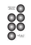
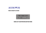
Equipson, S.A. www.equipson.es [email protected] QMAX 231 User Manual/Manual de usuario QMAX 231 31 BAND STEREO EQUALIZER ECUALIZADOR ESTEREO DE 31 BANDAS English Version Page 1 Versión Español Página 11 This symbol on the product or on its packaging indicates that this product shall not be trated as household waste. Instead it shall be handed over to the applicable collection point for the recycling of electrical an electronic equipment. By ensuring this product is disposed of correctly, you will help prevent potential negative consequences for the environment and human health, which could otherwise be caused by inappropriate waste handling of this product. The recycling of amterials will help to conserve natural resources. For more detailed information sabout recycling of this product, please contact your local city office, your household waste disposal service or the shop where you purchased the product. Este símbolo en su equipo o embalaje, indica que el presente producto no puede ser tratado como residuos domésticos normales, sino que deben entregarse en el correspondiente punto de recogida de equipos electrónicos y eléctricos. Asegurándose de que este producto es desechado correctamente, Ud. está ayudando a prevenir las consecuencias negativas para el medio ambiente y la salud humana que podrían derivarse de la incorrecta manipulación de este producto. EL reciclaje de materiales ayuda a conservar las reservas naturales. Para recibir más información, sobre el reciclaje de este producto, contacte con su ayuntamiento, su punto de recogida más cercano o el distribuidor donde adquirió el producto. Servicio Esta unidad dispone de una circuitería electrónica muy sofisticada y sólo deber ser manejada por personal especializado. " The information furnished in this manual does not include all of the details of design and engineering of this particular product; not does it cover every possible application or situation concerning its usage, which may occur during the installation, operation or maintenance of said FLEPCHER product. CAUTION! IMPORTANT THE PRODUCT REQUIRES CLASS 2 OUTPUT WIRING. Para prevenir el riesgo de descargas, no retire las tapas, no hay elementos de control para el usuario en el interior de la unidad. Diríjase a un técnico especializado. CAUTION TO PREVENT ELECTRIC SHOCK, DO NOT REMOVE TOP OR BOTTOM COVERS. NO USER SERVICEABLE PARTS INSI DE. REFER S E RV I C I N G TO Q U A L I F I E D S E RV I C E PERSONNEL. DISCONNECT POWER CORD BEFORE REMOVING REAR PANEL COVER TO ACCESS GAIN SWITCH. Shock Hazard - Do Not Enter Choc Hasard - N*entrent Schocke Hazard - Test Nicht Betrete Urto Hazard - Do Non Entrano WARNING TO REDUCE THE RISK OF ELECTRIC SHOCK, DO NOT EXPOSE THIS EQUIPMENT TO RAIN OR MOISTURE! Magnetic Field CAUTION: Do not locate sensitive high-gain equipment such as preamplifiers or tape decks directly above or below this unit. Because this amplifier has a high power density, it has a strong magnetic field which can induce hum into unshielded devices that are located nearby. This field is strongest just above and below the unit. If an equipment rack is used, we recommend locating the amplifier(s) at the bottom of the rack and the preamplifier or other sensitive equipment at the top. The lightning bolt triangle is used alert the user to the risk of electric shock User Manual / Manual de uso Pag. 20 The exclamation point triangle is used to alert the user to important operating and/or maintenance instructions. User Manual / Manual de uso Pag. 1 Printed on recycled paper. Important Safety Instructions 1 2 3 4. Esta unidad debe ser limpiada sólo con un paño sueva. Evite usar disolventes u otros detergentes. 5. Cuando mueva este equipo, hágalo dentro de su embalaje original para reducir el riesgo de daños. Read these instructions. Keep these instructions. Heed all warnings. Follow all instructions. Especificaciones 4 Do not use this apparatus near water. 5 6 7 Clean only with a damp cloth. Do not block any of the ventilation openings. Install in accordance with the manufacturer's instructions Do not install near any heat sources such as radiators, heat registers, stoves, or other apparatus that produce heat. 8 9 Do not install the safety purpose of he polarized or grounding-type plug. A polarized plug has two blades with one wide than the other. A grounding-type plug has two blades and third grounding prong. The wide blade or the third prong is provided for your safety. When the provided plug does not fit into your outlet, consult an electrician for replacement of the obsolete outlet. Protect the power cord from being walked on or pinched, particularly at plugs, convenience at plugs, convenience receptacles, and the point where they exit from the apparatus. 10 Only use power cord from attachments/accessories specified by the manufacturer. Use only with a cart, stand, bracket, or table specified by the manufacturer, or sold with the apparatus. When a cart is used, use caution when moving the cart/apparatus combination to 11 avoid injury from tip-over. Bandas de freciencia : Tipo de filtro : Dimen. potenciómetro : Rango : Conex. de entrada : Impedancia de salida : Nivel Max. de salidal: Filtro Low Cut: Filtro High Cut: Respuesta de frecuencia : THD +N : Relación señal ruido: Separación de canales: Alimentación : Consumo: Dimensiones : Peso: 2x31, 1/3 octava, ISO Q constante -3% 20mm y punto medio +/-6dB or +/-12dB seleccionable XLR y Euroblock balanceados <150 ohms +18dBm (bal.), +22dBm (desbal.) 10Hz a 250Hz, 12dB/oct 3Hz a 40kHz, 12dB/oct 20Hz a 20kHz, +0.5dB 0.01% -94dB >50dB/60dB 110V-230V~50/60Hz 12 W 483 x 88 x 216 mm 4.1kg 12 Unplug this apparatus during lightning storms or when unused for long Periods of time. Refer all servicing to qualified service personal. Servicing is required when the apparatus has been damaged in any way, such as power-supply cord or plug is damaged, liquid has been spilled or objects have fallen into the apparatus, the apparatus has been exposed to rain or 13 moisture, does not operate normally. User Manual / Manual de uso Pag. 2 User Manual / Manual de uso Pag. 19 Contents Antes de comenzar a usar este ecualizador, hay información que debería conocer y procedimientos que seguir. Su ecualizador está equipado con un conmutador Bypass, este conmutador, cuando está activado, todas las ecualizaciones serán canceladas, mientras que la señal de entrada pasa a través de la unidad con ganancia unitaria. El conmutador de rango permite configurar el máximo realce o corte de cada banda de ecualización entre 6 dB o 12 dB, Si aplica demasiada ganancia a la señal de entrada, el LED clip se iluminará. En este caso debe reajustar el control de nivel. Aquí tiene algunos consejos para su configuración inicial: 1. Configure todos los controles de volumen a su posición central 2. Configure todos los controles de frecuencia a su posición central 3. Seleccione el rango +/- 6 dB 4. Aplique señal a su sistema 5. Pulse bypass para salir de este modo 6. Si el LED clip se ilumina reduzca el nivel 7. Empiece a usar el ecualizador para configurar el sonido 8. Si no obtiene el nivel de ganancia necesario, conmute al rango +/- 12 dB 9. Si el el LED clip se ilumina continuamente, baje el nivel hasta que este LED sólo se ilumine ocasionalmente. Introduction....................................................................................4 Instruction for connections .........................................................4 Connection example..................................................................... 5 Control and Operation ..................................................................6 Warnings........................................................................................ 8 Specifications................................................................................ 9 Service............................................................................................10 Aplicaciones El ecualizador debe ser usado cuando se desee modificar la respuesta de frecuencia del sistema de audio. Un ecualizador gráfico es una potente herramienta que soluciona gran número de problemas y crea interesantes texturas. Avisos 1. Todas las instrucciones de funcionamiento deben ser leídas antes de usas este equipo. 2. Para reducir el riesgo de descargas eléctricas, no retire las cubiertas superior e inferior, dentro de la unidad no hay elementos de ajuste para el usuario. Diríjase a un técnico especializado. 3. No exponga la unidad a luz solar directa o fuentes de calor como estufas, radiadores u otras aplicaciones que generen calor. User Manual / Manual de uso Pag. 18 User Manual / Manual de uso Pag. 3 Introduction We congratulate you on choosing a FLEPCHER equalizer. You will find that its design makes using it very simple. The stereo 31 band graphic equalizer with frequency control of 20 Hz to 20kHz and a incorporates constant Q circuitry with a 3%center frequency accuracy. Special features include selectable range 6dB or 12dB, active balanced and unbalanced input/output connectors, RFI filters, variable level control, passive bypass switch, overload threshold LED, ground lift switch and selectable line voltage switch. Instruction For Connections The equalizer is for operation from 220-240 volt, 50-60Hz main supply. Do not remove the center grounding pin, in new installations and portable sound systems, or any situation in which the mains power is in question, it is wise to confirm the confirm the voltage and select the appropriate line voltage switch before connecting the instrument to power sources. There are two paralleled input and output connectors. XLR and Euro terminal are actively balanced with pin 2 or the tip being Hi, Pin 3 or the ring being Lo, and Pin 1 or sleeve being ground. Balanced output requires using Pin 2 of the XLR or the tip of the Euro terminal as output Hi (+) and using Pin 3 of the XLR or the ring of the Euro terminal as Lo (-). It does not require Pin 1 or signal ground. The signal exists differentially between the two balanced leads. Ground is used only for shielding to prevent potential hum. Paralleling input and output may be accomplished by using and of the three connectors. The equalizer is equipped with a rear panel Ground lift switch. After setting up your system and the system exhibits hum or buzzing, the problem is that there is a ground incompatibility between your equalizer and other equipment in the same system. There are several combinations that can be attempted.. (6) LED Clip: Un parpadeo ocasional de este LED is aceptable, pero si luce continuamente, debe reducir el nivel de salida de la unidad procedente. (7) Filtro Low Cut o HPF: Este filtro reduce las bajas frecuencias. Es útil p-ara eliminar zumbido de baja frecuencia. Su rango es ajustable desde 10 Hz a 250 Hz. Las frecuencias por debajo de este nivel no se ven afectadas. (8) Filtro High Cut o LPF: Este filtro reduce las altas frecuencias. Es útil p-ara eliminar soplidos de la señal. Su rango es ajustable desde 3 kHz a 40 kHz. Las frecuencias por encima de este nivel no se ven afectadas. (9) Level Control: Este contol controla el nivel de señal que entra en el ecualizador. En su posición en sentido horario es ganancia unitaria (no hay realce ni reducción). Si el LED Clip parpadea totalmente, baje el nivel de control para que sólo lo haga ocasionalmente. (10) Cable de red: Este cable es necesario para conectar la alimentación de su ecualizador. Nunca use un cable dañado ni el cable con el pin de masa eliminado. (11) Portafusible: El portafusible contiene el fusible de alimentación. Cambie sólo por otro de igual valor y tipo. Si el fusible continúa fundiéndose, consulte con un técnico especializado. (12) Conectores XLR balanceados: Pin 1: masa, Pin 2: +, Pin 3: Conectores Euroblock balanceados: Pin 1: entrada de señal +, Pin 2: entrada de señal -, Pin 3: Masa de señal de entrada. Pin 4: Masa de señal de salida, Pin 5: salida de señal +, Pin 6: salida de señal - CAUTION Always turn your amplifiers down before changing your ground around. Try different combinations of lifting ground on units that are supplied with ground lift switches or make sure all chassis are connected to earth ground, either through the A.C. Power cord ground or by the front panel rack mount screws. Signal levels from -10dB to +4dB are considered normal and at least 20dB of headroom exists above these levels. Do not directly connect microphones into the equalizer. Microphones require a pre amp. User Manual / Manual de uso Pag. 4 User Manual / Manual de uso Pag. 17 Control y Funcionamiento Connection Example MIC 1 MIC 2 MIC ᜀ MIC ᠀ MIC ᤀ MI㬀 L MI㬀 R AU㬀 1 AU㬀 2 AU㬀 3 LAM㌀ 11 1᠀ ᨀ 1ᰀ 㬀 㬀 㬀 㬀 㬀 㬀 R R R R R R MIC 3 L ✀ ✀ ✀ ✀ ✀ ✀ LINE IN LINE IN ─AL UN─AL INSERT ㌀⤀L SENS LINE IN LINE IN ─AL UN─AL ─AL UN─AL INSERT LINE IN ─AL UN─AL L L L 12㤀 ጀ ᄀ 1᠀ A 12 1ᤀ ᬀ 2ጀ R R R R LINE IN ─AL UN─AL INSERT INSERT ─AL UN─AL INSERT MI㬀 INSERT L MI㬀 INSERT R MONO SUM 13 ᰀ 21 1ᨀ L L L L INSERT MONITOR L MONITOR R ㌀ ⬀ ONE 1ᜀ 22 1ጀ 1ᬀ R R R R SENS SENS SENS SENS CHANNEL ᐀ SENS -3ጀ -3ጀ -3ጀ -3ጀ -3ጀ -3ጀ -2ጀ -2ጀ -2ጀ -2ጀ -2ጀ -2ጀ U U -ᜀ ጀ -ᜀ ጀ U U U U -ᜀ ጀ -ᜀ ጀ -ᜀ ጀ -ᜀ ጀ ᠀ ᠀ ᠀ ᠀ LE㤀 EL LE㤀 EL LE㤀 EL LE㤀 EL ᜀ ᤀ ᜀ ᤀ ᜀ ᤀ ᜀ ᤀ ᨀ ᨀ ᨀ ᨀ 3 3 3 3 ጀ -ᤀ ጀ 䜀 ─堀 ጀ -ᤀ ጀ 䜀 ─堀 ጀ -ᤀ ጀ 䜀 ─堀 ጀ -ᤀ ጀ 䜀 ─堀 ጀ -ᤀ ጀ 䜀 ─堀 ጀ -ᤀ ጀ 䜀 ─堀 1ጀ ጀ ⬀ 崀 1ጀ ጀ ⬀ 崀 1ጀ ጀ ⬀ 崀 1ጀ ጀ ⬀ 崀 1ጀ ጀ ⬀ 崀 1ጀ ጀ ⬀ 崀 2 ᬀ 2 ᬀ 2 ᬀ 2 ᬀ - - - - - - 3 ጀ 3 3 ጀ 3 3 ጀ 3 3 ጀ 3 3 ጀ 3 3 ጀ 3 1 ᰀ 1 ᰀ 1 ᰀ 1 ᰀ ᤀ ᤀ ᤀ ᤀ ᤀ ᤀ ᤀ ᤀ ᤀ ᤀ ᤀ ᤀ ጀ ጀ ጀ ጀ 1ጀ 1ጀ 1ጀ 1ጀ ᰀ ᰀ ᰀ ᰀ ᰀ ᰀ ᰀ ᰀ ᰀ ᰀ ᰀ ᰀ ⬀ ⤀ ⬀ ⤀ ⬀ ⤀ ⬀ ⤀ ⬀ ⤀ ⬀ ⤀ 12 12 12 12 12 12 12 12 12 12 12 12 1᠀ 1᠀ 1᠀ 1᠀ ᰀ -1ጀ 13-1ᜀ 1ᨀ -1ᬀ ᠀ -ᤀ 1᠀ 1᠀ 1᠀ 1᠀ 1᠀ 1᠀ 1᠀ 1᠀ 1-2⸀ 1-2⸀ 1-2⸀ 1-2⸀ 1-2⸀ 1-2⸀ 11 11 11 11 ᨀ -ᬀ 11-12 1᠀ -1ᤀ 1ᰀ -2ጀ ⨀ AIN ⨀ AIN ⨀ AIN ⨀ AIN ㌀ ⤀ L A⤀ L 2T⸀ 2ᜀ ጀ ᤀ ⸀ ⬀ 崀 2ᜀ ጀ ᤀ ⸀ ⬀ 崀 ጀ ጀ ጀ ጀ 2ᜀ ጀ ᤀ ⸀ ⬀ 崀 2ᜀ ጀ ᤀ ⸀ ⬀ 崀 2ᜀ ጀ ᤀ ⸀ ⬀ 崀 2ᜀ ጀ ᤀ ⸀ ⬀ 崀 22䜀 ─ 22䜀 ─ 22䜀 ─ 22䜀 ─ ᠀ M⤀ M⤀ M⤀ M⤀ M⤀ M⤀ - - ᜀ ᤀ - - - - - - - - 3 ጀ 3 3 ጀ 3 3 ጀ 3 3 ጀ 3 3 ጀ 3 3 ጀ 3 3 ጀ 3 3 ጀ 3 3 ጀ 3 3 ጀ 3 ᤀ ᤀ ᤀ ᤀ ᨀ 3 ᤀ ᤀ ᤀ ᤀ ᤀ ᤀ ᤀ ᤀ ᤀ ᤀ ᤀ ᤀ ᤀ ᤀ ᤀ ᤀ ᰀ ᰀ ᰀ ᰀ ᰀ ᰀ ᰀ ᰀ ᰀ ᰀ ᰀ ᰀ ᰀ ᰀ ᰀ ᰀ ᰀ ᰀ ᰀ ᰀ 2 ᬀ 12 12 12 12 12 12 12 12 12 12 12 12 12 CHANNEL 2 ⬀ ⤀ ⬀ ⤀ ⬀ ⤀ ⬀ ⤀ 12 12 12 12 12 12 12 1 ᰀ MI㬀 TO 2T⸀ ጀ 1ጀ 1᠀ 1᠀ 1᠀ 1᠀ 1᠀ 1᠀ 1᠀ 1᠀ 1᠀ 1᠀ 1᠀ 1᠀ 1᠀ 1᠀ 1᠀ 1᠀ 1᠀ 1᠀ 1᠀ 1᠀ 2T⸀ LE㤀 EL ᠀ - - - - - - - - - - ᜀ ᤀ 3 ጀ 3 3 ጀ 3 3 ጀ 3 3 ጀ 3 3 ጀ 3 3 ጀ 3 3 ጀ 3 3 ጀ 3 3 ጀ 3 3 ጀ 3 ᤀ ᤀ ᤀ ᤀ ᤀ ᤀ ᤀ ᤀ ᤀ ᤀ ᤀ ᤀ ᤀ ᤀ ᤀ ᤀ ᤀ ᤀ ᤀ ᤀ ᨀ 3 ᰀ ᰀ ᰀ ᰀ ᰀ ᰀ ᰀ ᰀ ᰀ ᰀ ᰀ ᰀ ᰀ ᰀ ᰀ ᰀ ᰀ ᰀ ᰀ ᰀ 2 ᬀ L⤀ L⤀ L⤀ L⤀ L⤀ L⤀ L⤀ L⤀ L⤀ L⤀ 12 12 12 12 12 12 12 12 12 12 12 12 12 12 12 12 12 12 12 12 1 ᰀ 2T⸀ TO MI㬀 ጀ 1ጀ 1᠀ 1᠀ 1᠀ 1᠀ 1᠀ 1᠀ 1᠀ 1᠀ 1᠀ 1᠀ 1᠀ 1᠀ 1᠀ 1᠀ 1᠀ 1᠀ 1᠀ 1᠀ 1᠀ 1᠀ MONO SUM ㌀ OST AU㬀 AU㬀 AU㬀 AU㬀 AU㬀 AU㬀 AU㬀 AU㬀 AU㬀 AU㬀 1 1 1 1 1 1 1 1 1 1 ㌀ RE ㌀ RE ㌀ RE ㌀ RE ㌀ RE ㌀ RE ㌀ RE ㌀ RE ㌀ RE ㌀ RE ᜀ ᬀ 㤀 ㌀ O㨀 ER ㌀ RE ᜀ ᬀ 㤀 ጀ 1ጀ ጀ 1ጀ ጀ ጀ ጀ ጀ ጀ ጀ ጀ ጀ 1ጀ 1ጀ 1ጀ 1ጀ 1ጀ 1ጀ 1ጀ 1ጀ 1ᤀ 1ጀ AU㬀 AU㬀 AU㬀 AU㬀 AU㬀 AU㬀 AU㬀 AU㬀 AU㬀 AU㬀 AU㬀 1 2 2 2 2 2 2 2 2 2 2 ᤀ ሀ ㌀ RE ሀ ㌀ RE ሀ ㌀ RE ሀ ㌀ RE ሀ ㌀ RE ሀ ㌀ RE ሀ ㌀ RE ሀ ㌀ RE ሀ ㌀ RE ሀ ㌀ RE ሀ ㌀ RE A⤀ L 3 ጀ ጀ ጀ ጀ ጀ ጀ ጀ ጀ ጀ ጀ ጀ ጀ ጀ ጀ ጀ ጀ ጀ ጀ ጀ -3 AU㬀 AU㬀 AU㬀 AU㬀 AU㬀 AU㬀 AU㬀 AU㬀 AU㬀 AU㬀 AU㬀 2 -ᤀ 3 3 3 3 3 3 3 3 3 3 ㌀ OST ㌀ OST ㌀ OST ㌀ OST ㌀ OST ㌀ OST ㌀ OST ㌀ OST ㌀ OST ㌀ OST ㌀ OST ㌀ OST A⤀ L -ᰀ ጀ 1ጀ AU㬀 2 ጀ 1ጀ ጀ 1ጀ 1ጀ ጀ 1ጀ ጀ 1ጀ ጀ 1ጀ ጀ 1ጀ ጀ 1ጀ ጀ 1ጀ ጀ 1ጀ ጀ 1 2 3 -12 ጀ ጀ ጀ ጀ ጀ ጀ ጀ ጀ ጀ ጀ ㌀ AN ㌀ AN ㌀ AN ㌀ AN ㌀ AN ㌀ AN ─AL ─AL ─AL ─AL 1 1 1 1 1 1 1 1 1 1 1 1 1 1 1 1 1 1 1 2 3 2 3 2 2 3 3 2 2 3 3 2 2 3 3 2 2 3 3 2 2 3 3 2 2 3 3 2 2 3 3 2 2 3 3 2 3 -1ᤀ AU㬀 3 ᜀ ᜀ ᜀ ᜀ A⤀ L ᜀ ᜀ ᜀ ᜀ ᜀ ᜀ ᜀ ᜀ ᜀ ᜀ ᜀ ᜀ ᜀ ᜀ ᜀ ᜀ 1ጀ ጀ AU㬀 3 ᠀ ᠀ ᠀ ᠀ ᠀ ᠀ ᠀ ᠀ ᠀ ᠀ ᠀ ᠀ ᠀ ᠀ ᠀ ᠀ ᠀ ᠀ ᠀ ᠀ ON ON ON ON ON ON ON ON ON ㌀⤀L 9 ጀ ጀ 8 ጀ ጀ 7 ጀ ጀ 6 5 3 4 2 ጀ ጀ ጀ 1ጀ AU㬀 1 ጀ 1ጀ ጀ 1ጀ ጀ ጀ ጀ ጀ ጀ ጀ ጀ ጀ 1ጀ 1ጀ 1ጀ 1ጀ 1ጀ 1ጀ 1ጀ 1ጀ ON 1ጀ 1ጀ ጀ ጀ ጀ 1ጀ 1ጀ 1ጀ 1ጀ 1ጀ 1ጀ 1ጀ 1ጀ ᠀ ᠀ ᠀ ᠀ ᠀ ᠀ ᠀ ᠀ ᠀ ᠀ ᠀ ᠀ ᠀ ጀ ጀ ጀ ጀ ጀ ጀ ጀ ጀ ጀ ጀ 1ጀ 1ጀ 1ጀ ᠀ ᠀ ᠀ ᠀ ᠀ ᠀ ᠀ ᠀ ᠀ ᠀ 1᠀ 1᠀ 1᠀ 1ጀ 1ጀ 1ጀ 1ጀ 1ጀ 1ጀ 1ጀ 1ጀ 1ጀ 1ጀ 2ጀ 2ጀ 2ጀ 1᠀ 1᠀ 1᠀ 1᠀ 1᠀ 1᠀ 1᠀ 1᠀ 1᠀ 1᠀ 2᠀ 2᠀ 2᠀ 2ጀ 2ጀ 2ጀ 2ጀ 2ጀ 2ጀ 2ጀ 2ጀ 2ጀ 2ጀ 3ጀ 3ጀ 3ጀ ㌀ ⤀ L ㌀ ⤀ L ㌀ ⤀ L ㌀ ⤀ L ㌀ ⤀ L ㌀ ⤀ L ㌀ ⤀ L ㌀ ⤀ L 3ጀ 3ጀ 3ጀ 3ጀ 3ጀ 3ጀ 3ጀ 3ጀ 3ጀ 3ጀ ᜀ ጀ ᜀ ጀ ᜀ ጀ 1 MIXER (1) Interruptor de red: Permite conmutar el encendido/apagado de la unidad PRECAUCION Todos los controles de nivel y volumen deben estar a “0” o a su posición mínima antes de encender la unidad. Siempre encienda el ecualizador antes de encender los amplificadores, y siempre apague el ecualizador despues de haberlo hecho con los amplificadores. (2) Controles de nivel de filtro: Cada uno de estos potenciómetros controla el nivel de salida de cada uno de los 31 filtros paso banda. (La posición central es masa para garantizar la respuesta plana). (3) Conmutador de rango: El rango de ganancia es conmutable (como grupo) desde +/- 6 dB a +/- 12 dB para un máximo de realce/corte. (4) Bypass: Use el modo bypass para comparar el material ecualizado y por ecualizar, or para que la señal no se vea afectada por el paso a través del ecualizador. En este modo, la entrada es dirigida directamente a la salida. (5) LED señal: Cuando se ilumina el LED verde, signifaca que hay señal de entrada, si el LED parpadea alguna sección del ecualizador está a 5 dB de “clipear”, entonces debe reducir el nivel del ecualizador o de la unidad precedente para evitar la distorsión. User Manual / Manual de uso Pag. 16 MAINS HIGH OUT 2 MID 100-120ሀ 200-240 VAC 50ሀ 60 Hz OUT 2 LOW OUT 2 INPUT 2 HIGH OUT 1 MID OUT 1 LOW OUT 1 INPUT 1 ᘀ WA㰀 # SERIAL NO: ! CAUTION " FOR CONTINUED PROTECTION AGAINST FIRE HA㴀 ARD REPLACE ONLY WITH SAME TYPE AND RATING OF FUSE FUSE: SLOW-BLOW FUSE VOLTAGE 315mA(100-120V) SEL. 160mA(200-240V) HIGH OUT Input CH 2 CH 1 SENSITIVIT㰀 MODE 12 Bridge Input 10 2ጀ 1ᰀ ᬀ 12 1᠀ ᨀ 11 1ᤀ ᜀ ᠀ ᤀ L MI㬀 R MONITOR LE㤀 EL 1ጀ 22 21 1ᜀ 1ᬀ 13 1ᨀ ᰀ USE ONL㰀 WITH 2᠀ ጀ VF FUSE 11 3 ᠀ WA㰀 INPUT MID㼀 HIGH OUT MID OUT LOW㼀 MID OUT LOW OUT BRIDGE , PARALLEL STEREO ) BRIDGED RISK OF ELECTRIC SHOCK DO NOT OPEN + WARNING က TO REDUCE THE RISK OF FIRE OR ELECTRICAL SHOCK,DO NOT EXPOSE THIS EQUIPMENT TO RAIN OR MOISTURE. NO USER SERVICEABLE PARTS INSIDE REFER SERVICING TO QUALIFIED SERVICE PERSONAL * ᐀ .ᜀ ᜀ V SPEAKER OUTPUT: ᐀ .ጀ V CLASS 2 WIRING PERMITTED CLASS ᐀ WIRING REQUIRED OUTPUT ASSIGNMENT ጀ .ᨀ V IN BRIDGE MONO OUT 2 OUT 1 OUT᐀ : PIN᐀ : SIGNAL CH᐀ CONNECTION PIN᐀ က : GROUND CH᐀ PIN2 : SIGNAL CH2 PIN2က : GROUND CH2 RISQUE DE CHOC ELECTRIQUE က NE PAS OUVRIR. : SIGNAL CH2 OUT2: PIN᐀ PIN᐀ က : GROUND CH2 PIN2 PIN2က MODEL: PIN᐀ : SIGNAL GND AC VOLTS: GND BRIDGE MONO OUTPUT PIN2: SIGNAL AMPS: : SIGNAL OUT᐀ : PIN᐀ PINᘀ : SIGNAL က RATED OUTPUT: PIN2 : GROUND AVIS: INPUT GROUND 1 2 LIFT User Manual / Manual de uso Pag. 5 LOUD SPEAKERS Control and Operation Ejemplo de conexionado MIC 1 MIC 2 MIC 3 LINE IN 6 LINE IN MIC 4 MIC 5 MIC MI㬀 L MI㬀 R LAM㌀ AU㬀 1 AU㬀 2 AU㬀 3 11 1᠀ ᨀ 1ᰀ L L L L 12㤀 ጀ ᄀ 1᠀ A 12 1ᤀ ᬀ 2ጀ R R R R LINE IN ─AL UN─AL ─AL UN─AL ㌀⤀L SENS LINE IN ─AL UN─AL INSERT INSERT LINE IN ─AL UN─AL LINE IN ─AL UN─AL INSERT INSERT MI㬀 INSERT L MI㬀 INSERT R MONO SUM ─AL UN─AL INSERT 13 ᰀ 21 1ᨀ L L L L INSERT MONITOR L MONITOR R ㌀ ⬀ ONE 1ᜀ 22 1ጀ 1ᬀ R R R R SENS SENS SENS SENS CANAL 1 SENS -3ጀ -3ጀ -3ጀ -3ጀ -3ጀ -3ጀ -2ጀ -2ጀ -2ጀ -2ጀ -2ጀ -2ጀ U U -ᜀ ጀ -ᜀ ጀ U U U U -ᜀ ጀ -ᜀ ጀ -ᜀ ጀ -ᜀ ጀ ᠀ ᠀ ᠀ ᠀ LE㤀 EL LE㤀 EL LE㤀 EL LE㤀 EL ᜀ ᤀ ᜀ ᤀ ᜀ ᤀ ᜀ ᤀ ᨀ ᨀ ᨀ ᨀ 3 3 3 3 ጀ -ᤀ ጀ 䜀 ─堀 ጀ -ᤀ ጀ 䜀 ─堀 ጀ -ᤀ ጀ 䜀 ─堀 ጀ -ᤀ ጀ 䜀 ─堀 ጀ -ᤀ ጀ 䜀 ─堀 ጀ -ᤀ ጀ 䜀 ─堀 1ጀ ጀ ⬀ 崀 1ጀ ጀ ⬀ 崀 1ጀ ጀ ⬀ 崀 1ጀ ጀ ⬀ 崀 1ጀ ጀ ⬀ 崀 1ጀ ጀ ⬀ 崀 2 ᬀ 2 ᬀ 2 ᬀ 2 ᬀ - - - - - - 3 ጀ 3 3 ጀ 3 3 ጀ 3 3 ጀ 3 3 ጀ 3 3 ጀ 3 1 ᰀ 1 ᰀ 1 ᰀ 1 ᰀ ᤀ ᤀ ᤀ ᤀ ᤀ ᤀ ᤀ ᤀ ᤀ ᤀ ᤀ ᤀ ጀ ጀ ጀ ጀ 1ጀ 1ጀ 1ጀ 1ጀ ᰀ ᰀ ᰀ ᰀ ᰀ ᰀ ᰀ ᰀ ᰀ ᰀ ᰀ ᰀ ⬀ ⤀ ⬀ ⤀ ⬀ ⤀ ⬀ ⤀ ⬀ ⤀ ⬀ ⤀ 12 12 12 12 12 12 12 12 12 12 12 12 1᠀ 1᠀ 1᠀ 1᠀ ᰀ -1ጀ 13-1ᜀ 1ᨀ -1ᬀ ᠀ -ᤀ 1᠀ 1᠀ 1᠀ 1᠀ 1᠀ 1᠀ 1᠀ 1᠀ 1-2⸀ 1-2⸀ 1-2⸀ 1-2⸀ 1-2⸀ 1-2⸀ 11 11 11 11 ᨀ -ᬀ 11-12 1᠀ -1ᤀ 1ᰀ -2ጀ ⨀ AIN ⨀ AIN ⨀ AIN ⨀ AIN ㌀ ⤀ L A⤀ L 2T⸀ 2ᜀ ጀ ᤀ ⸀ ⬀ 崀 2ᜀ ጀ ᤀ ⸀ ⬀ 崀 ጀ ጀ ጀ ጀ 2ᜀ ጀ ᤀ ⸀ ⬀ 崀 2ᜀ ጀ ᤀ ⸀ ⬀ 崀 2ᜀ ጀ ᤀ ⸀ ⬀ 崀 2ᜀ ጀ ᤀ ⸀ ⬀ 崀 22䜀 ─ 22䜀 ─ 22䜀 ─ 22䜀 ─ ᠀ M⤀ M⤀ M⤀ M⤀ M⤀ M⤀ - - ᜀ ᤀ - - - - - - - - 3 ጀ 3 3 ጀ 3 3 ጀ 3 3 ጀ 3 3 ጀ 3 3 ጀ 3 3 ጀ 3 3 ጀ 3 3 ጀ 3 3 ጀ 3 ᤀ ᤀ ᤀ ᤀ ᨀ 3 ᤀ ᤀ ᤀ ᤀ ᤀ ᤀ ᤀ ᤀ ᤀ ᤀ ᤀ ᤀ ᤀ ᤀ ᤀ ᤀ ᰀ ᰀ ᰀ ᰀ ᰀ ᰀ ᰀ ᰀ ᰀ ᰀ ᰀ ᰀ ᰀ ᰀ ᰀ ᰀ ᰀ ᰀ ᰀ ᰀ 2 ᬀ 12 12 CANAL 2 ⬀ ⤀ ⬀ ⤀ ⬀ ⤀ ⬀ ⤀ 12 12 12 12 12 12 12 12 12 12 12 12 12 12 12 12 12 12 1 ᰀ MI㬀 TO 2T⸀ ጀ 1ጀ 1᠀ 1᠀ 1᠀ 1᠀ 1᠀ 1᠀ 1᠀ 1᠀ 1᠀ 1᠀ 1᠀ 1᠀ 1᠀ 1᠀ 1᠀ 1᠀ 1᠀ 1᠀ 1᠀ 1᠀ 2T⸀ LE㤀 EL ᠀ - - - - - - - - - - ᜀ ᤀ 3 ጀ 3 3 ጀ 3 3 ጀ 3 3 ጀ 3 3 ጀ 3 3 ጀ 3 3 ጀ 3 3 ጀ 3 3 ጀ 3 3 ጀ 3 ᤀ ᤀ ᤀ ᤀ ᤀ ᤀ ᤀ ᤀ ᤀ ᤀ ᤀ ᤀ ᤀ ᤀ ᤀ ᤀ ᤀ ᤀ ᤀ ᤀ ᨀ 3 ᰀ ᰀ ᰀ ᰀ ᰀ ᰀ ᰀ ᰀ ᰀ ᰀ ᰀ ᰀ ᰀ ᰀ ᰀ ᰀ ᰀ ᰀ ᰀ ᰀ 2 ᬀ L⤀ L⤀ L⤀ L⤀ L⤀ L⤀ L⤀ L⤀ L⤀ L⤀ 12 12 12 12 12 12 12 12 12 12 12 12 12 12 12 12 12 12 12 12 1 ᰀ 2T⸀ TO MI㬀 ጀ 1ጀ 1᠀ 1᠀ 1᠀ 1᠀ 1᠀ 1᠀ 1᠀ 1᠀ 1᠀ 1᠀ 1᠀ 1᠀ 1᠀ 1᠀ 1᠀ 1᠀ 1᠀ 1᠀ 1᠀ 1᠀ MONO SUM ㌀ OST AU㬀 AU㬀 AU㬀 AU㬀 AU㬀 AU㬀 AU㬀 AU㬀 AU㬀 AU㬀 1 1 1 1 1 1 1 1 1 1 ㌀ RE ㌀ RE ㌀ RE ㌀ RE ㌀ RE ㌀ RE ㌀ RE ㌀ RE ㌀ RE ㌀ RE ᜀ ᬀ 㤀 ㌀ O㨀 ER ㌀ RE ᜀ ᬀ 㤀 ጀ 1ጀ ጀ 1ጀ ጀ ጀ ጀ ጀ ጀ ጀ ጀ ጀ 1ጀ 1ጀ 1ጀ 1ጀ 1ጀ 1ጀ 1ጀ 1ጀ 1ᤀ 1ጀ AU㬀 AU㬀 AU㬀 AU㬀 AU㬀 AU㬀 AU㬀 AU㬀 AU㬀 AU㬀 AU㬀 1 2 2 2 2 2 2 2 2 2 2 ᤀ ሀ ㌀ RE ሀ ㌀ RE ሀ ㌀ RE ሀ ㌀ RE ሀ ㌀ RE ሀ ㌀ RE ሀ ㌀ RE ሀ ㌀ RE ሀ ㌀ RE ሀ ㌀ RE ሀ ㌀ RE A⤀ L 3 ጀ ጀ ጀ ጀ ጀ ጀ ጀ ጀ ጀ ጀ ጀ ጀ ጀ ጀ ጀ ጀ ጀ ጀ ጀ ጀ ጀ ጀ ጀ ጀ ጀ ጀ ጀ ጀ 1ጀ AU㬀 1 ጀ 1ጀ ጀ 1ጀ ጀ ጀ ጀ ጀ ጀ ጀ ጀ ጀ 1ጀ 1ጀ 1ጀ 1ጀ 1ጀ 1ጀ 1ጀ 1ጀ -3 AU㬀 AU㬀 AU㬀 AU㬀 AU㬀 AU㬀 AU㬀 AU㬀 AU㬀 AU㬀 AU㬀 2 -ᤀ 3 3 3 3 3 3 3 3 3 3 ㌀ OST ㌀ OST ㌀ OST ㌀ OST ㌀ OST ㌀ OST ㌀ OST ㌀ OST ㌀ OST ㌀ OST ㌀ OST ㌀ OST A⤀ L -ᰀ ጀ 1ጀ AU㬀 2 1ጀ ጀ 1ጀ ጀ ጀ 1ጀ ጀ 1ጀ ጀ 1ጀ ጀ 1ጀ ጀ 1ጀ ጀ 1ጀ ጀ 1ጀ ጀ 1ጀ 1 2 3 2 7 8 9 -12 ጀ ጀ ጀ ጀ ጀ ጀ ጀ ጀ ጀ ጀ ㌀ AN ㌀ AN ㌀ AN ㌀ AN ㌀ AN ㌀ AN ─AL ─AL ─AL ─AL 1 1 1 1 1 1 1 1 1 1 1 1 1 1 1 1 1 1 1 2 3 2 3 2 2 3 3 2 2 3 3 2 2 3 3 2 2 3 3 2 2 3 3 2 2 3 3 2 2 3 3 2 2 3 3 2 3 -1ᤀ AU㬀 3 ᜀ ᜀ ᜀ ᜀ A⤀ L ᜀ ᜀ ᜀ ᜀ ᜀ ᜀ ᜀ ᜀ ᜀ ᜀ ᜀ ᜀ ᜀ ᜀ ᜀ ᜀ 1ጀ ጀ AU㬀 3 ᠀ ᠀ ᠀ ᠀ ᠀ ᠀ ᠀ ᠀ ᠀ ᠀ ᠀ ᠀ ᠀ ᠀ ᠀ ᠀ ᠀ ᠀ ᠀ ᠀ ON ON ON ON ON ON ON ON ON ㌀⤀L 6 5 3 4 ON 1ጀ 1ጀ ጀ ጀ ጀ 1ጀ 1ጀ 1ጀ 1ጀ 1ጀ 1ጀ 1ጀ 1ጀ ᠀ ᠀ ᠀ ᠀ ᠀ ᠀ ᠀ ᠀ ᠀ ᠀ ᠀ ᠀ ᠀ ጀ ጀ ጀ ጀ ጀ ጀ ጀ ጀ ጀ ጀ 1ጀ 1ጀ 1ጀ ᠀ ᠀ ᠀ ᠀ ᠀ ᠀ ᠀ ᠀ ᠀ ᠀ 1᠀ 1᠀ 1᠀ 1ጀ 1ጀ 1ጀ 1ጀ 1ጀ 1ጀ 1ጀ 1ጀ 1ጀ 1ጀ 2ጀ 2ጀ 2ጀ 1᠀ 1᠀ 1᠀ 1᠀ 1᠀ 1᠀ 1᠀ 1᠀ 1᠀ 1᠀ 2᠀ 2᠀ 2᠀ 2ጀ 2ጀ 2ጀ 2ጀ 2ጀ 2ጀ 2ጀ 2ጀ 2ጀ 2ጀ 3ጀ 3ጀ 3ጀ ㌀ ⤀ L ㌀ ⤀ L ㌀ ⤀ L ㌀ ⤀ L ㌀ ⤀ L ㌀ ⤀ L ㌀ ⤀ L ㌀ ⤀ L 3ጀ 3ጀ 3ጀ 3ጀ 3ጀ 3ጀ 3ጀ 3ጀ 3ጀ 3ጀ ᜀ ጀ ᜀ ጀ ᜀ ጀ 1 2 3 2ጀ 1ᰀ ᬀ 12 1᠀ ᨀ 11 1ᤀ ᜀ ᠀ ᤀ L MI㬀 R MONITOR LE㤀 EL 1ጀ 22 21 1ᜀ 1ᬀ 13 1ᨀ ᰀ MEZCLADOR 1 11 10 QMX 231 12 (1) Power Switch: To turn the equalizer ON or OFF CAUTION MAINS HIGH OUT 2 MID 100-120ሀ 200-240 VAC 50ሀ 60 Hz ! FUSE: SLOW-BLOW FUSE VOLTAGE 315mA(100-120V) SEL. 160mA(200-240V) CAUTION HIGH OUT 1 MID OUT 1 LOW OUT 1 INPUT 1 ᘀ WA㰀 Bridge Input Input CH 2 CH 1 SENSITIVIT㰀 MODE PROCESADOR (4) Bypass: Use the bypass mode to compare equalized un unequalized material, or the bypass the unit in the event of power loss. When bypass, the input signal is routed directly to output jack. Pag. 6 INPUT 2 ᠀ WA㰀 INPUT MID㼀 HIGH OUT MID OUT LOW㼀 MID OUT LOW OUT HIGH OUT (3) Filter Range Switch: The gain range of the filter sliders is switchable (as a group) from +/- 6 dB to +/- 12 dB for maximum boost/cut capability. User Manual / Manual de uso LOW OUT 2 " FOR CONTINUED PROTECTION AGAINST FIRE HA㴀 ARD REPLACE ONLY WITH SAME TYPE AND RATING OF FUSE (2) Filter Level controls: each of these sliders control the output level of each of the 31 band pass filter (Center detent position is ground for guaranteed flat response.) BRIDGE , PARALLEL STEREO ) BRIDGED RISK OF ELECTRIC SHOCK DO NOT OPEN + WARNING က TO REDUCE THE RISK OF FIRE OR ELECTRICAL SHOCK,DO NOT EXPOSE THIS EQUIPMENT TO RAIN OR MOISTURE. NO USER SERVICEABLE PARTS INSIDE REFER SERVICING TO QUALIFIED SERVICE PERSONAL * ᐀ .ᜀ ᜀ V SPEAKER OUTPUT: ᐀ .ጀ V CLASS 2 WIRING PERMITTED CLASS ᐀ WIRING REQUIRED OUTPUT ASSIGNMENT ጀ .ᨀ V IN BRIDGE MONO OUT 2 OUT 1 OUT᐀ : PIN᐀ : SIGNAL CH᐀ CONNECTION PIN᐀ က : GROUND CH᐀ PIN2 : SIGNAL CH2 AVIS: PIN2က : GROUND CH2 RISQUE DE CHOC ELECTRIQUE က NE PAS OUVRIR. : SIGNAL CH2 OUT2: PIN᐀ PIN᐀ က : GROUND CH2 PIN2 PIN2က MODEL: PIN᐀ : SIGNAL GND AC VOLTS: GND BRIDGE MONO OUTPUT PIN2: SIGNAL AMPS: : SIGNAL OUT᐀ : PIN᐀ PINᘀ : SIGNAL က RATED OUTPUT: PIN2 : GROUND GROUND (5) Signal LED: When LED light in green , there is input signal, the LED will flicker when any section of the equalizer is within 5 dB od clipping, then tou should turn down the level or reduce the output level of the preceding component to audible distortion. OUT 2 # SERIAL NO: USE ONL㰀 WITH 2᠀ ጀ VF FUSE All volume or level controls must be at “0” or minimum position before turning power on. Always turn on your equalizer before your power amplifiers are turned on, and always turn off your equalizer after the power amplifiers have been turn off. LIFT User Manual / Manual de uso Pag. 15 ALTAVOCES (6) Introducción Felicidades por la elección de un ecualizador WORK. Encontrará que su diseño lo hace fácil de utilizar. La unidad incorpora un ecualizador gráfico de 31 bandas con control de frecuencia de 20 Hz a 20 kHz y circuitería de Q constante con una corrección de frecuencia central del 3%. Sus características especiales incluyen selector de rango 6 dB o 12 dB, conectores de entrada/salida balanceados y desbalanceados. Filtros RF, control de nivel variable. Bypass, LED de umbral de sobrecarga, conmutador de masa y selector de tensión de entrada. Instrucciones para el conexionado (7) Low Cut Filter (or HPF ) : The Low Cut filter rolls off (decreases ) lower frequencies. This is useful for decreasing rumble or low frequency hum from a signal. Its range is adjustable from 10Hz to 250Hz.Frequencies below this setting are rolled off, while frequencies above are Unaffected. (8) Hi Cut Filter (or LPF ) : The Hi Cut filter rolls off (decreases ) higher frequencies. This is useful for reducing hiss or sibilance form a signal. signal. Its range is adjustable form 3kHz to 40kHz. Frequencies above this setting are rolled off, while frequencies above are unaffected. (9) Level Control : This control sets the signal level coming into the equalizer. Its full clockwise position is unity gain (no boost or cut ). If the Clip LED is lit continuously, turn down this control until it only flickers occasionally. El ecualizador funciona con alimentación 220-240 V 50-60 Hz. No elimine el pin central de masa, en una nueva instalación o sistema portátil, confirme la alimentación y seleccione con el conmutador el voltaje apropiado antes de conectar cualquier instrumento. Clip LED: Occasional flickering of the Clip LED is acceptable, but if it remain on continuously you should turn down the level control or reduce the output level of the preceding component to avoid audible distortion. Hay dos conexiones paralelas de entrada y salida. Los conectores XLR y Euroblock están balanceados . La salida balanceada requiere que se use el pin 2 del XLR y Euroblock como + y el pin 3 como -. El pin 1 será masa. (10) Power Cord : This cord is used to connect AC power to your equalizer. Never use a damaged or cut power cord. Never use with the ground pin removed. El ecualizador está equipado con un conmutador de masa situado en el panel trasero. Si despues de conectar el sistema, se aprecia zumbidos, el problema puede ser ocasionado por incompatibilidades de masa entre el ecualizador y otras unidades del sistema. Utilice el conmutador para hacerlo desaparecer. (11) PRECAUCION APAGUE LOS AMPLIFICADORES ANTES DE CAMBIAR EL SISTEMA DE MASA Fuse Holder : The fuse holder contains the primary Ac fuse. Only replace with the same type if necessary (0.6 amp ). If ever the fuse continues to blow after replacing, stop using the EQ ,and serviced by qualified personnel. (12) Balanced XLR connectors: Pin1=Ground, Pin2=Hot(+), Pin3=Cold(-); Balanced Euro terminal strip: Pin1=Input signal Hot(+), Pin2=Input signal Cold(-), Pin3=Input signal Ground, Pin4=Output signal Ground, Pin5=Output signal Hot(+), Pin6=Output signal Cold(-) Pruebe diferentes combinaciones conectando la masa de las unidades con la alimentación o asegurándose que el chasis está conectado a la toma de tierra de la red. Niveles de señal desde -10 dB a +4 dB son considerados normales y existe al menos 20 dB de resonancia. No conecte micrófonos directamente al ecualizador, éstos necesitan preampificadores User Manual / Manual de uso Pag. 14 User Manual / Manual de uso Pag. 7 Contenidos Before starting to use you equalizer, there is some information you should know and procedures you should follow. Youur equalizer is equipped with a bypass switch. The bypass switch, when active, all equalization setting will be cancels while allowing signal to flow through the unit at unity gain. A range control switch is provide which allows you to set maximum boost or cut for each band of equalization to either 6 dB or 12 dB. If you apply to much gain to the input signal, the clip LED will light. If the clip light is on, you must readjust the level control. Here are some tips to help you with your initial setup: 1. Set the level control to their center position 2. Set all frequency controls to their center position 3. Select the +/- 6 dB range setting 4. Apply signal to your system 5. Take the unit out of bypass 6. If the clip light is on, turn down the level control 7. Star using the equalizer to shape your sound 8. If do not have enough gain for your needs, switch the range to +/- 12 dB setting 9. In the clip LED lights continuosly while you are applying EQ, turn down the level control until Clip LED light only occasionally. Introduccion....................................................................................14 Instrucciones de Conexionado.....................................................14 Ejemplo de conexión..................................................................... 15 Control y Funcionamiento.............................................................16 Avisos..............................................................................................18 Especificaciones.............................................................................19 Servicio............................................................................................20 Applications The equalizer may used wherever modification for the frequency contour of a sound is needed. A graphic equalizer is powerful tool for solving a numberr of audio problems and creating interesting textures. Warnings 1. All operations isntruction should be read before using this equipment 2. To reduce the risk of electrical shock, do not remove cover or back. No user service part inside. Refer servicing to a qualified service technician. 3. Do not expose to direct sunlight or heat sources: such radiators, stoves, or other aplliances that produce heat. User Manual / Manual de uso Pag. 8 User Manual / Manual de uso Pag. 13 Instrucciones Importantes de Seguridad 4. This unit should be cleaned only with a damp cloth. Avoid solvents or other cleaning detergents. 5. When moving this equipment it should be placed in its original carton and packing. This will reduce the risk of damage in transit. 1. Lea estas instrucciones 2. Conserve estas instrucciones 3. Tenga presente todos los avisos Specifications 4. Sigua las instrucciones 5. No use este aparato cerca del agua 6. Limpie la unidad con un paño humedo 7. No bloquee las aberturas de ventilación. Instálelo de acuerdo a las instrucciones del fabricante. 8. No lo instale cerca de fuentes de calor como radiadores, registros de calor, estufas u otras aplicaciones que generen calor. 9. Conecte la unidad con una clavija de toma de tierra para su propia seguridad, en caso de que la clavija mural no disponga de ello, consulte a un electricista. 10. Proteja el cable de red contra pisadas o pinzamientos, particularmente en las clavijas o donde sale de la unidad. 11. Use únicamente cable y accesorios especificados por el fabricante. Frequency Bands : Filter Type : Slider Travel : Range : Input connections : OUTPUT Impedance : Max. Output Level: Low Cut Filter: High Cut Filter: Frequency Response : THD +Noise : Signal to Noise Ratio: Channel separation: Power : Power Consumption: Dimension : Weight: 2x31, 1/3 octave, ISO spacing Constant Q -3% center accuracy 20mm positive center detect +/-6dB or +/-12dB selectable active balanced XLR and Eruo-style strip Type. <150 ohms +18dBm (bal.), +22dBm (unbal.) 10Hz to 250Hz, 12dB/oct 3Hz to 40kHz, 12dB/oct 20Hz to 20kHz, +0.5dB 0.01% -94dB >50dB/60dB 110V-230V~50/60Hz 12watts 3.5"H X19"W x 8.5:D (2U) 9.1bs.(4.1kg) 12. Use estantes o mesas especificadas por el fabricante, cuando lo use, tenga la precaución de moverlo junto con la unidad para evitar caídas o daños. 13. Desconecte la unidad durante tormentas eléctricas o si no va a usarlo durante largo tiempo. 14. Diríjase a un técnico especializado ante cualquier problema en la unidad, cable cortado o dañado, liquido u objetos en el interior o el aparato ha estado expuesto a la lluvia o la humedad o no parezca funcionar con normalidad. User Manual / Manual de uso Pag. 12 User Manual / Manual de uso Pag. 9 Service IMPORTANTE ESTE PRODUCTO REQUIERE CABLEADO DE SALIDA CLASE 2 This unit has very sophisticated circuitry and should only be serviced by a fully trained technician. This is why each unit bears the following label: " PRECAUCION CAUTION! To prevent electric shock, do not remove covers. No user serviceable parts inside. Refer servicing to a qualified technician. PA R A P R E V E N I R E L R I E S G O D E DESCARGA, NO RETIRE LAS TAPAS SUPERIOR E INFERIOR, NO HAY PARTES DE USO EN EL INTERIOR. DIRIJASE A UN TECNICO ESPECIALIZADO. DESCONECTE EL CABLE DE RED ANTES DE QUITAR LAS TAPAS Shock Hazard - Do Not Enter Choc Hasard - N*entrent Schocke Hazard - Test Nicht Betrete Urto Hazard - Do Non Entrano ATENCION PARA REDUCIR EL RIESGO DE DESCARGA, NO EXPONGA LA UNIDAD A LA LLUVIA O HUMEDAD Campo Magnetico PRECAUCION: No situe equipos de gran sensibilidad como previos o pletinas directamente sobre esta unidad, debido al campo magnetico presente en estas unidades, los cuales pueden inducir ruidos y zumbidos El triangulo le alerta del riesgo de descargas User Manual / Manual de uso Pag. 10 El punto de exclamación le alerta de una instrucción importante User Manual / Manual de uso Pag. 11