1
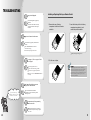
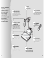
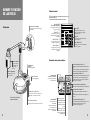
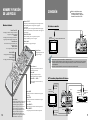
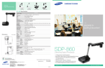
SALES NETWORK
SAMSUNG TECHWIN CO., LTD.
145-3, Sangdaewon 1-Dong, Jungwon-Gu,
Sungnam, Kyungki-Do, Korea 462-703
TEL : +82-31-740-8137~8141 FAX: +82-31-740-8145
SAMSUNG OPTO-ELECTRONICS AMERICA, INC.
ELECTORONIC IMAGING DIV.
40 Seaview Drive, Secaucus NJ 07094, U.S.A
TEL : +1-201-902-0347 FAX: +1-201-902-0429
SAMSUNG OPTO-ELECTRONICS UK LTD.
Samsung House, 1000 Hillswood Drive
Hillswood Business Park Chertsey Surrey KT16 OPS
TEL : +44 (0)1932 455 308 FAX: +44 (0)1932 455 325
SAMSUNG TECHWIN MOSCOW OFFICE
LENNINGRADSDY PR-KT, 37A. KORP.14
RUSSIA, 125167, MOSCOW
TEL : +7-095-258-9296, 9298 FAX: +7-095-258-9297
TIANJIN SAMSUNG OPTO-ELECTRONICS CO., LTD .
7 Pingchang Rd, Nankai Dist, Tianjin, P.R China
Post Code : 300190
TEL : +86-22-2761-4599 FAX: +86-22-2769-7558
http://www.samsungpresenter.com
P/No.: 6806-0526-01A
crecom 04.10
www.samsungpresenter.com
SAFETY
PRECAUTIONS
CONTENTS
SAFETY PRECAUTIONS
WHERE THE VIDEO PRESENTER IS NEEDED
CHECKING PARTS
Accessories Supplied
NAME AND FUNCTION OF PART
Front View
Control Panel
Connectors at the back side
Remote Controller
CONNECTION
To TV or Monitor
To TV or Monitor and External AV Device
To Power Outlet
To Microphone
Connecting to PC
How to install the Head Lamp
How to install the Lightbox
OPERATION
Using Control Buttons
PRECAUTIONS AND STORAGE
Storage
Safety Precautions
TROUBLESHOOTING
Installing or Replacing Battery on
Remote Controller
SPECIFICATIONS
LENS MAGNIFICATION RATE
Adapter Lens
2
3
6
7
7
8
8
9
9
10
11
11
11
12
12
13
13
13
14
15
18
18
18
20
21
22
22
22
Follow these safety instructions when setting up
and using your Video Presenter:
1. Do not place the presenter on an unstable cart,
stand, or table
2. Do not use the presenter near water or sources of
heat.
3. Use the type of power source indicated on the
presenter. If you are not sure of the power
available, consult your dealer or power company.
4. Place the presenter near a wall outlet where the
plug can be easily unplugged.
5. Take the following precautions for the plug.
Failure to comply with these precautions could
result in sparks or fire:
Do not insert the plug into an outlet with dust
present. Insert the plug firmly into the outlet.
6. Do not overload wall outlets, extension cords, or
integral convenience receptacles. This can cause
fire or electric shock.
7. Do not place the presenter where the cord can be
walked on. It may result in fraying or damage to
the plug.
8. Unplug the presenter from the wall outlet before
cleaning. Use a damp cloth for cleaning. Do not
use liquid or aerosol cleaners.
9. Do not block the slots and openings in the
presenter case. They provide ventilation and
prevent the presenter from overheating. Do not put
the presenter on a sofa, rug, or other soft surface
or in a built-in installation, unless proper ventilation
is provided.
10. Never push objects of any kinds through cabinet
slots. Never spill liquid of any kinds into the
presenter.
11. Except as specifically explained in this User's
Manual, do not attempt to service this product
yourself. Refer all servicing to qualified service
personnel. Opening or removing covers may
expose you to dangerous voltages and other
hazards.
12. Unplug the presenter during lightning storms or
when it will not be used for extended periods.
13. Do not place the presenter and remote controller
on top of heat-producing equipment or in a
heated place, such as a car.
14. Unplug the presenter from the wall outlet and
refer servicing to qualified service personnel
under the following conditions:
• When the power cord or plug is damaged or
frayed.
• If liquid has been spilled into the presenter, or it
has been exposed to rain or water.
• If it does not operate normally when you follow
the operating instructions, or if it exhibits a
distinct change in performance, indicating a
need for service.
• If it has been dropped or the cabinet has been
damaged.
15. Don’t take the camera unit unfolded and turn to
the leftmost or rightmost, or the presenter can fall
upside down.
FCC Compliance Statement
This equipment has been tested and found to comply with the limits for a class A digital device, pursuant
to part 15 of the FCC Rules. These limits are designed to provide reasonable protection against harmful
interference when the equipment is operated in a commercial environment. This equipment generates,
uses, and can radiate radio frequency energy and, if not installed and used in accordance with the
instruction manual, may cause harmful interference to radio communications.
Operation of this equipment in a residential area is likely to cause harmful interference in which case the
user will be required to correct the interference at his own expense.
3
Thank you for purchasing
this product.
Your video presenter can
project a wide variety of
items onto PC, TV (monitor)
with simple handling. High
resolution and definition
ensures fine image quality.
Head Lamp
Lamp easily attachable
Menu display on the screen
Automatic focusing
When you control the functions by use of
remote controller or control panel, the
controlling status will be displayed on the
screen.
When you press the automatic focusing button,
a precise focusing on the object can be
performed. If automatic focusing is inadequate,
you can focus manually.
Free-angle camera head
Remote Controller
The camera head can be freely rotated
through 270° to right or left, 120° to top or
bottom. You can see the surrounding objects
and instruction as well as the data on the plate
All the functions are
controlled by use of remote
controller.
Adapter lens
It is used to project the documents and films
(positive/negative) closely.
Control panel
You can control main functions using the
buttons on control panel built in the main
body.
Easy flexible body
Each part can be bent and stretched so that you
can project any type of objects easily.
Lightbox (Option)
This backlight illuminator is useful to
project the slides or films. It is easily
attached and removed.
4
5
WHERE THE VIDEO
PRESENTER IS
NEEDED
CHECKING PARTS
Accessories Supplied
Video conference
Remote Controller
Adapter lens and lens cap
Adapter
The video presenter display clearly the
image of a real thing at hand as well as
detailed data such as report, form, chart,
etc. on the screen. Thus, the entire staffs
concentrate on the same topic so you can
manage the conference efficiently.
They are attached to the main
body at factory.
Medical or scientific research
You can use the image such as X-ray or slide as it is
on your Video Presenter.
Education field
Audio/Video cables
Head lamp
It can create a powerful visual image by connecting
to multi-vision at the new product presentation or
exhibition.
User’s manual
Required to connect
with a TV equipped
with S-video terminal.
Required to connect to
PC with USB-terminal.
Light box(Option)
User’s manual USB Capture program
User’s manual
CD for program
install
Carring bag
Design preview
Your Video Presenter may be effectively used to
display the design artwork of a catalog or slide
through imaging process.
Lamp easily attachable
6
USB cable
You can utilize the presenter as the audio-video aid which
shows the printed materials like textbook, the visual data
and even the products that the students made.
Yellow jack: Video cable
White jack: Audio cable
Presentation and Exhibition
S-video cable
Required to display a slide
or film
7
NAME AND FUNCTION
OF PART
Control Panel
You can find the same buttons on the remote controller.
These buttons perform the same functions.
POWER button
Front View
Head lamp connector
Used to connect the head lamp
with the body
Used to turn power on
and off.
IRIS
/
AWC button
button
Used to adjust the
luminosity of image on
the screen
Used to adjust the color (white
balance) on the screen automatically
POWER
IRIS
AWC
button
FOCUS
AF
Used to adjust the focus
manually.
ZOOM
NEGA/POSI
FOCUS
ZOOM
/
/
Video IN jack 1/2
Connection terminals
Connected to the video output terminals of TV or Video.
Connect it when you want to see the image on your
presenter and the one on another AV equipment
alternately.
(See page 9.)
Adapter lens
Control panel
(See page 9.)
Video OUT jack 1/2
RS-232C PC interface
connectors
Connected to video input terminal of TV or monitor.
Connect it when you want to send the image on your
Video Presenter to TV or monitor. The signals from both
jacks are equivalent.
Used to connect with
RS-232C cable.
S-VIDEO OUT
POWER IN
DC12V IN
VIDEO
AUDIO
IN
1
IN
2
1
2
1
OUT
1
Lightbox connector
It is a spot to join microphone with the Body.
Connected to the PC with
USB terminal.
Connect it when you
want to see the image on
the PC screen with USB
terminal.
8
Used to connect the power cable of adapter.
2
Audio OUT jack 1/2
Connected with audio input terminal of TV or Video.
Sound of microphone or external AV equipment will
be output.
USB OUT jack
Microphone connector
Power IN jack
2
OUT
Used to connect the lightbox with the body
(DC 15V, 600mA or less)
To receive the signal from
remote controller
NEGA/POSI button
Connectors at the back side
Camera head
Used to display the close
objects.
Used to set the focusing
automatically
Used to convert the film as
Positive/Negative
button
Used to adjust the size of
image on the screen
To rotate 120 to
top or bottom,
and 270 to right
or left
AF button
Audio IN jack 1/2
S-video OUT jack
Connected to the TV
with S-video input
terminal.
Even though the
external input is
selected, it only send
the image from the
main body.
Connected with audio output terminal of TV or Video.
Connect it when you want to hear the sound from
another AV equipments.
9
NAME AND FUNCTION
OF PART
CONNECTION
Use the white plug to connect audio
terminal, and the yellow (or red) plug
to connect video terminal.
INT/EXT button
Remote Controller
Focus F/N button
Used to focus the image displayed on the
video presenter manally
AF button
Used to focus the image displayed on the
video presenter automatically
Reverse button
Used to select internal Image or external Image
Internal (INT): To see the image on this presenter
External (EXT): To see the image sent from another AV
equipment through monitor (if connected to this
presenter)
To TV or Monitor
POSI/NEGA button
Positive (POSI): To see the general state or positive film
Negative (NEGA): To see the negative film
Lamp button
Yellow
TV, Monitor,
LCD Projector
to video input terminal
Used to turn the head lamp on and off
S-VIDEO OUT
Used to put the image into reverse up/down
or right/left
POWER IN
DC12V IN
VIDEO
AUDIO
IN
Freeze button
1
Used to freeze the image on the screen
IN
2
1
OUT
Power button
SHARP + button
1
Used to turn power on
and off
Used to see the image sharper
2
OUT
2
1
2
Video Presenter
SHARP - button
You may use either 'Video OUT 1' or 'Video OUT 2' jack.
Used to see the image duller
Connect 'S-video OUT' terminal when you have a TV with S-Video terminal. If 'S-Video OUT' terminal is
used, you can get more clear image, but the signal from external AV source will not be available.
Volume +/- button
Connect 'RF output terminal' to TV with only RF terminal.
Used to increase or decrease the
volume of microphone
AWC button
Used to adjust the screen color (white
balance) automatically
RED+/-button and BLUE +/-button
To TV or Monitor and External AV Device
Used to increase the red or blue color
factor
WIDE button
TV, Monitor,
LCD Projector
to audio
input
terminal
White
Yellow
Used to reduce the image size of an object
TELE button
Preset button
10
Used to save the current status (Zoom,
Focus, Lamp, Color etc).
When you use the video presenter on
another place, you need not to repeat
the same procedures but the saved
status will be automatically set only
by pressing the “Active” button.
Select the button (1~4) and press it
within 4 seconds after pressing
“Save/Active” button.
S-VIDEO OUT
Used to enlarge the image size of an object
to video
output
terminal
to audio
output
terminal
POWER IN
DC12V IN
VIDEO
AUDIO
IN
BRIGHT + button
1
IN
2
1
OUT
Used to make the screen brighter
1
2
AV Device (VTR, Camcorder)
OUT
2
1
2
BRIGHT - button
Video Presenter
Used to make the screen darker
to video
input
terminal
Yellow
White
11
CONNECTION
After connecting to PC properly, install the USB
Device Driver and SVP-5300 Capture program.
The programs ave supplied with presenter.
RS-232C Communication cable is not supplied with
this product.
Connecting to PC
To Power Outlet
S-VIDEO OUT
POWER IN
USB Cable
DC12V IN
This video presenter can operate on free
voltage (100~240V).
VIDEO
AUDIO
IN
1
IN
2
1
OUT
1
2
USB Connected
with USB Port in
PC
OUT
1
2
2
Video Presenter
To use 220V
RS-232C Cable
RS-232C
Connected with
RS-232C Port in
PC
Adapter
S-VIDEO OUT
To use 110V
Personal
Computer
POWER IN
DC12V IN
VIDEO
AUDIO
IN
1
IN
2
1
OUT
Use a converter for 110V
fixing into the power cord
1
2
OUT
2
1
2
Video Presenter
To Microphone
How to install the Head Lamp
When the light of head lamp is projected
to the script, it means that the head
lamp is installed in this place.
Yellow
TV, Monitor,
LCD Projector
To Video Input terminal
Head lamp
S-VIDEO OUT
POWER IN
DC12V IN
VIDEO
IN
1
2
1
OUT
1
Microphone(ф6.3)
To Audio Input terminal
It is nipper shaped. Clip it
where you want.
AUDIO
IN
2
OUT
2
1
2
How to install the Lightbox
Video Presenter
You can use it to see the slides or negative films.
Pay attention not to scratch. You cannot see the clear
image if there is scar.
White
How to use
Microphone is not supplied with this product.
Please purchase a microphone.
If the microphone is connected, the presenter
can send the image and sound at the same
time so it is more convenient to use in
presentation or exhibition.
12
You can switch on and off the Lightbox by using the
power switch at the side.
Lightbox
13
OPERATION
Before operating
Make sure the Power is connected properly.
Make sure the desired devices (TV, Monitor) are
connected to output terminal. (See page 11)
Using Control Buttons
1. Stretch the camera head as shown and
remove the lens cap.
3. Press the POWER button.
Choosing INT/EXT signal
Switching Positive/Negative
Lens cap
Make sure the adapter lens is properly attached.
If not, attach it.
You may press POWER button on the control
panel.
The message of “Please wait” will appear on
the screen in a few seconds, and the projected
image will be displayed on the presenter.
When the presenter is connected with TV, select
the external video input. If connected to TV
with RF terminal, set the TV channel to CH4.
2. Make the camera lens facing the script.
Whenever you press the button, INT and EXT
appear alternately on the screen.
Whenever you press the button, POSI and
NEGA will appear alternately on the screen.
POSI: To see the normal script or picture
If there is no external AV device connected to
the presenter, EXT will not appear even though
you press [INT/EXT] button.
NEGA: To see the negative film
INT: To see the image through this presenter
EXT: To see the image and hear the sound from
external AV device through TV or Monitor
connected with this presenter when external AV
device is connected to the terminal of 'video
input' and 'audio input' in the video presenter.
When the adapter lens is required
Adapter lens is required when you project the
copies, documents or films (positive/negative) on
the desktop or lightbox. (Focusing distance with
adapter lens attached: 24~32cm)
Adapter lens may not be required if you use it for
another purposes. (Focusing distance without
adapter lens: 80cm~ )
Turning Light On/Off
▲ POSITIVE
While the presenter is powered on, press the
[LAMP] button to turn the head lamp on and
off.
Make sure the adapter lens is attached and pay
attention to the distance between body and object.
You cannot focus on the object properly when the
distance between object and camera is out of
focusing range stated above.
14
The image will be reversed if the camera lens is
facing forward.
In this case, adjust the camera head angle by
turning to right or left, or press the image
[Reverse] button.
The light box is turned on as defalt.
You can also use the switch of light box.
▲ NEGATIVE
15
OPERATION
Adjusting Color
Zooming
Adjusting Sharpness/Automatic Focus
Preset button
Used to save the current status (Zoom, Focus, Lamp,
Color etc).
When you use the video presenter on another place,
you need not to repeat the same procedures but the
saved status will be automatically set only by
pressing the “Active” button.
Select the button (1~4) and press it within 4 seconds
after pressing “Save/Active” button.
If you press [AWC] button, color will be
adjusted automatically. To obtain the best
result, put the camera lens facing white paper
and press [AWC] button.
Press [Wide] or [Tele] button on the remote
controller or [zoom+] or [zoom-] on the control
panel.
If you want to fine adjust, press [RED+/-] or
[BLUE+/-] button. Press [RED+/-] button to
adjust the red factor strongly, and [BLUE+/-]
button to adjust the blue factor strongly.
If you press [+] button the image gets sharper,
and [-] button the image gets duller.
Adjusting Brightness
Automatic focusing
Press the [AF] button on the remote controller
or [AF] button on the control panel.
The color level will be displayed on the screen.
▲ Wide (Zoom -)
Manual focusing
Press the [Focus N/F] button on the remote
control or [Focus +/-] button on the control
panel.
Press [Bright +] or [Bright -] on remote controller or
[Iris +] or [Iris -] on the control panel.
Bright (Iris) + : When the image of object is dark
Bright (Iris) - : When the image of object is bright
Image Reverse and Image Freeze
If the distance to object is out of range or if the
lens is not attached properly, auto focusing may
not work. At this time, check it again.
Focusing distance with adapter lens attached :
24~32cm
Focusing distance without adapter lens: 80cm~
The operating range of remote controller
▲ Tele (Zoom +)
Image reverse
Press [Reverse] button to make the image reverse.
mirror → flip → flip + mirror →
normal
[(reverse right/left)→ (reverse up/down)→
(reverse right/left and up/down)→ (normal)]
16
Image freeze
When you press [Freeze] button, the image is held
on the screen. It is convenient to replace the script
or picture with next one.
If you press [Freeze] button again, the freezing
mode will be released.
Volume Button
Use this button to adjust the volume of
microphone (if connected with video presenter).
When the Auto focusing may not work properly
Object in a dark area
The background is too bright
When some objects being close to the lens and others
being far away at the same time.
Object with little difference in brightness such as wall
or air
Repeated horizontal or vertical lines.
Object standing behind the window is stained with
spot or water drop
Object reflecting a strong beam
When the wire net or screen close to lens is piled up
to the object in a distance
17
PRECAUTIONS AND
STORAGE
Storage
Safety Precautions
1. Stretch the camera head as shown and
cover the lens cap.
It is illegal to make a copy of a film,
photograph, or book protected by the
copyright without permission.
Be careful not to drop.
Do not use benzene or thinner to clean
the presenter.
Lens cap
2. Fold the presenter as shown.
When moving the presenter, fold the
presenter a little and hold as shown.
Do not apply excessive force on
the external cable.
18
Do not put or drop a heavy
thing on it.
When the presenter needs cleaning, wipe
it with soft and dry cloth.
When you don't use it for a long time, pull out
the power cord and keep it with a cover.
Do not use the presenter in a humidity place.
Be careful not to spill a liquid on it.
19
TROUBLESHOOTING
Image is not displayed.
Check the brightness is properly
adjusted.
Check the video cable is correctly
connected with the video output
terminal.
Installing or Replacing Battery on Remote Control
1. Remove the cover of battery
compartment at the back of remote
controller.
2. Insert the battery cells in the battery
compartment as positive(+) ends
contact the positive terminals.
Image is not focused on the screen
Check the lens is properly attached to the
camera.
Press “AF (Auto Focus)” button for
automatic focusing.
Check the object is placed too close.
Battery cell type: AAA type 1.5V
The image of slide or negative film is
not displayed.
Check the lightbox turns on.
Set the camera lens facing the film.
Check the lens is properly attached.
Check if you set the “NEGA/POSI” button
correctly.
3. Put the cover in place.
Caution
Random replacement of built-in battery by
other types of batteries may cause explosion.
Thus, the battery shall be replaced by the
same battery. And the used batteries shall be
disposed carefully because they can cause
environment pollutions.
Head lamp will not light up as soon
as you press “LAMP” button.
If you still have any
problems, contact to your
dealer to ask service.
It is a normal because the built-in
protection circuit is activated to protect
the lamp circuit.
The presenter will not operate by
remote controller.
Check the battery cells in the remote
controller. If they are used up, replace
new ones.
20
21
SPECIFICATIONS
Optical
Sysetm
Zoom Lens
Shooting Area
Focus
Iris
Head lamp
F 1.4 ~ 2.7, f=3.9 ~ 62.4, 16× Power Zoom
210 x 297mm (max.), 18 x 24mm (min.)
Manual / Auto
Manual / Auto
Attachable
Image
TV system
Pick-up device
Effective pixels
Sync. system
Resolution
Color (WB)
Sharpness
S/N Ratio
Negative/Positive
On Screen Display
Input Selection
NTSC/PAL standard
1/4" IT CCD (NTSC:410,000pixels, PAL:470,000pixels)
768(H)×494(V)
Internal Sync.
H: 470 TV Line
AWC/Manual
Manual
More than 48 dB
Selectable
Built-in
3-channels (Internal:1, External:2)
Digital
Process
Image Rotation
Image Freeze
Preset
Mechanical : Max. 270。Electrical : Flip/Mirror
Available
Available (up to 4 user settings)
USB
RS-232C
Video Input
Video Output
Audio
USB 2.0
Built-in
Video (RCA/75 Ω Unbalance) x 2
Video (RCA/75 Ω Unbalance) x 2, USB Output x 1
Input : Microphone(φ 6.3, 600Ω, -65dB) x 1, RCA x2
Output : RCA (≦ 10 ㏀, -10dB) x 2
Power source
DC 12V (Exclusive adapte INPUT : AC 100V~240V, Free Voltage,
50/60Hz OUTPUT : 12V, 3.5A)
Terminal
Power
source
Dimension
182 (W) × 430 (D)× 482 (H) mm (Operation)
Weight
3.7Kg
※Specifications subject to change without notice to enhance the quality and performance of product.
LENS MAGNIFICATION RATE
Adapter Lens (Working distance 328 mm)
Zoom
Territory of view field
Lens magnification
21" Monitor
29" Monitor
33" Monitor
Wide(‐)
280 × 210 (A4)
0.013X
1.44X
2.1X
2.36X
240 × 180 (B5)
0.0152X
1.69X
2,45X
2.75X
32 × 24 (Film)
0.114X
12.7X
18.4X
20.6X
18 ×13.5 (Min.)
0.2X
22.2X
32.2X
36.2X
Standard
Tele(+)
WWW.SAMSUNGPRESENTER.COM
22
PRECAUCIONES DE
SEGURIDAD
CONTENIDO
PRECAUCIONES DE SEGURIDAD . . . . . . . . . . . . . . . . . . . . . . . . . . . . . . . . . . . . . . . . . . . . . . 3
EJEMPLOS DE APLICACIÓN DEL EQUIPO DE PRESENTACIÓN DE VÍDEO . . . . . . . . . . . . . . . . . . . . 6
COMPROBACIÓN DE LAS PIEZAS . . . . . . . . . . . . . . . . . . . . . . . . . . . . . . . . . . . . . . . . . . . . . . 7
Accesorios . . . . . . . . . . . . . . . . . . . . . . . . . . . . . . . . . . . . . . . . . . . . . . . . . . . . . . . . . . . 7
NOMBRE Y FUNCIÓN DE LAS PIEZAS . . . . . . . . . . . . . . . . . . . . . . . . . . . . . . . . . . . . . . . . . . . 8
Vista frontal . . . . . . . . . . . . . . . . . . . . . . . . . . . . . . . . . . . . . . . . . . . . . . . . . . . . . . . . . . 8
Panel de control . . . . . . . . . . . . . . . . . . . . . . . . . . . . . . . . . . . . . . . . . . . . . . . . . . . . . . . 9
Conectores de la parte posterior . . . . . . . . . . . . . . . . . . . . . . . . . . . . . . . . . . . . . . . . . . . 9
Mando a distancia . . . . . . . . . . . . . . . . . . . . . . . . . . . . . . . . . . . . . . . . . . . . . . . . . . . . . . 10
CONEXIÓN . . . . . . . . . . . . . . . . . . . . . . . . . . . . . . . . . . . . . . . . . . . . . . . . . . . . . . . . . . . . 11
Al televisor o monitor . . . . . . . . . . . . . . . . . . . . . . . . . . . . . . . . . . . . . . . . . . . . . . . . . . . 11
Al TV o monitor y dispositivo de AV externo . . . . . . . . . . . . . . . . . . . . . . . . . . . . . . . . . . . . 11
Conexión a la toma de alimentación . . . . . . . . . . . . . . . . . . . . . . . . . . . . . . . . . . . . . . . . . 12
Conexión del micrófono . . . . . . . . . . . . . . . . . . . . . . . . . . . . . . . . . . . . . . . . . . . . . . . . . . 12
Conexión al PC . . . . . . . . . . . . . . . . . . . . . . . . . . . . . . . . . . . . . . . . . . . . . . . . . . . . . . . . 13
Cómo instalar la lámpara . . . . . . . . . . . . . . . . . . . . . . . . . . . . . . . . . . . . . . . . . . . . . . . . . 13
Cómo instalar la caja de luz. . . . . . . . . . . . . . . . . . . . . . . . . . . . . . . . . . . . . . . . . . . . . . . 13
FUNCIONAMIENTO . . . . . . . . . . . . . . . . . . . . . . . . . . . . . . . . . . . . . . . . . . . . . . . . . . . . . . . 14
Cómo utilizar los botones de control . . . . . . . . . . . . . . . . . . . . . . . . . . . . . . . . . . . . . . . . . 15
PRECAUCIONES Y ALMACENAMIENTO . . . . . . . . . . . . . . . . . . . . . . . . . . . . . . . . . . . . . . . . . . 18
Almacenamiento. . . . . . . . . . . . . . . . . . . . . . . . . . . . . . . . . . . . . . . . . . . . . . . . . . . . . . . 18
Precauciones de seguridad . . . . . . . . . . . . . . . . . . . . . . . . . . . . . . . . . . . . . . . . . . . . . . . . 18
RESOLUCIÓN DE PROBLEMAS . . . . . . . . . . . . . . . . . . . . . . . . . . . . . . . . . . . . . . . . . . . . . . . 20
ISustitución de las pilas del mando a distancia . . . . . . . . . . . . . . . . . . . . . . . . . . . . . . . . . . 21
ESPECIFICACIONES . . . . . . . . . . . . . . . . . . . . . . . . . . . . . . . . . . . . . . . . . . . . . . . . . . . . . . 22
LENTE DE AUMENTO . . . . . . . . . . . . . . . . . . . . . . . . . . . . . . . . . . . . . . . . . . . . . . . . . . . . . 22
Lente del adaptador . . . . . . . . . . . . . . . . . . . . . . . . . . . . . . . . . . . . . . . . . . . . . . . . . . . . . . 22
2
Siga estas instrucciones de seguridad al
configurar y utilizar el presentador digital:
1. No coloque el presentador en un carro, soporte o
mesa inestable.
2. No utilice el presentador cerca de agua o fuentes
de calor.
3. Use el tipo de fuente de alimentación que se
indica en el presentador. Si no está seguro de la
alimentación disponible, consulte al distribuidor o
a la compañía eléctrica.
4. Coloque el presentador cerca de una toma donde
pueda desenchufar el aparato fácilmente.
5. Tenga en cuenta estas precauciones para el
enchufe.
Si no cumple estas precauciones podrían
producirse chipas o incendios:
No introduzca el enchufe en una toma con polvo.
Inserte el enchufe bien en la toma.
6. No sobrecargue las tomas, los cables de
extensión o las tomas de corriente integrales, ya
que podría causar un incendio o descarga
eléctrica.
7. No coloque el presentador donde puedan pisar el
cable, ya que puede destrozar o dañar el enchufe.
8. Desenchufe de la pared el presentador antes de
limpiarlo. Utilice un paño húmedo para la limpieza.
No utilice productos de limpieza líquidos o de
aerosol.
9. No bloquee las ranuras y las aberturas de la
carcasa del presentador, ya que ofrecen
ventilación y evitan que se recaliente el aparato.
No coloque el presentador en un sofá, alfombra u
otra superficie suave o en una instalación
integrada, a menos que esté bien ventilada.
10. No coloque nunca objetos de ningún tipo en las
ranuras del armario. Nunca derrame líquido de
ningún tipo en el presentador.
11. A menos que se especifique en este Manual del
usuario, no intente reparar este producto usted
mismo. Encargue el mantenimiento a personal
de servicio cualificado. Si abre o quita cubiertas
puede exponerse a tensión peligrosa y otros
peligros.
12. Desenchufe el presentador durante tormentas de
rayos o cuando no se utilice durante mucho
tiempo.
13. No coloque el presentador ni el mando a
distancia sobre un equipo que produzca calor o
en un lugar con calefacción, como un coche.
14. Desenchufe el presentador de la pared y
encargue el mantenimiento a personal de
servicio cualificado con las siguientes
condiciones:
• Cuando el cable o enchufe de alimentación esté
dañado o destrozado.
• Si se ha derramado líquido en el presentador o
si se ha expuesto a lluvia o agua.
• Si no funciona con normalidad cuando sigue las
instrucciones de funcionamiento o si muestra
señales de cambio en el rendimiento, lo que
indica que necesita reparación.
• Si se ha caído o si el armario se ha dañado.
15. Al coger la unidad de la cámara sin plegar y
girarla completamente a izquierda o derecha, el
equipo de presentación se puede caer.
Declaración de cumplimiento de FCC
Este equipo se ha probado y cumple los límites de dispositivos digitales de clase A, conforme a la parte
15 de la normativa FCC. Estos límites se han diseñado para ofrecer protección razonable contra
interferencias nocivas cuando el equipo funciona en un entorno comercial. Este equipo genera, utiliza y
puede radiar energía de radiofrecuencia y, si no se instala y se utiliza conforme al manual de
instrucciones, puede causar interferencias dañinas a las comunicaciones de radio.
El funcionamiento de este equipo en una zona residencial puede causar interferencias dañinas, en cuyo
caso el usuario deberá corregirlas corriendo con los gastos.
3
Gracias por haber adquirido
este producto.
El equipo de presentación
de vídeo puede proyectar
una gran variedad de
elementos en PC, TV
(monitor) de forma sencilla.
La alta resolución y
definición garantizan una
gran calidad de imagen.
Lámpara
Lámpara de fácil montaje
Menú en pantalla
Enfoque automático
Al controlar las distintas funciones mediante
el mando a distancia o el panel de control, en
la pantalla se muestran las funciones.
Al pulsar el botón de enfoque automático se
puede realizar un enfoque de precisión del
objeto. Si el enfoque automático no le satisface,
puede realizar el enfoque manual.
Cabezal de la cámara
de ángulo libre
Mando a distancia
Todas las funciones se
controlan mediante el mando a
distancia.
El cabezal de la cámara se puede girar de
forma libre 270° a izquierda y derecha y 120º
de arriba abajo. Se pueden ver los objetos de
alrededor y al profesor, así como los datos de
la placa
Lente del adaptador
Se utiliza para proyectar los documentos y
películas fotográficas (positivo/negativo) de
cerca.
Panel de control
Puede controlar las funciones principales
mediante los botones del panel de control
integrado en la unidad principal.
Carcasa flexible y
sencilla
Todas las piezas se pueden doblar y estirar, de
modo que pueda proyectar cualquier tipo de
objeto fácilmente.
4
Caja de la lámpara
Este iluminador de luz de fondo es muy
útil para proyectar diapositivas o películas
fotográficas. De fácil montaje y desmontaje.
5
EJEMPLOS DE APLICACIÓN
DEL EQUIPO DE
PRESENTACIÓN DE VÍDEO
COMPROBACIÓN DE
LAS PIEZAS
Accesorios suministrados
Vídeo conferencia
Lente del adaptador y tapa de la lente Adaptador
Mando a distancia
El equipo de presentación de vídeo
muestra claramente las imágenes reales,
así como datos detallados, como informes,
formularios, gráficos, etc. en pantalla. De
este modo, todo el personal puede
concentrarse en el mismo tema y la
conferencia se desarrolla de forma eficaz.
Estos elementos vienen unidos
a la unidad principal de fábrica.
Investigación médica o científica
Puede utilizar imágenes como rayos X o
diapositivas en el equipo de presentación de vídeo.
Campo educativo
Cables de audio/vídeo Cable de S-vídeo
Necesario para conectarse a
un televisor provisto de un
terminal de S-vídeo.
Lámpara
El equipo es capaz de crear potentes imágenes
visuales al conectarse a equipos de multivisión en
presentaciones y muestras de nuevos productos.
Necesario para conectarse a
un PC con tomas de USB.
Manual del
usuario
Caja de luz (opcional)
Manual del
CD para la
usuario del
instalación
programa de
del programa
captura mediante
USB
Bolsa de transporte
Vista preliminar de diseño
El equipo de presentación de vídeo se puede emplear
de forma eficaz para mostrar diseños de un catálogo o
diapositivas mediante el tratamiento de imágenes.
Lámpara de fácil montaje
6
Manual del usuario
Puede utilizar el equipo de presentación como herramienta de
audio y vídeo para mostrar material impreso como libros de
texto, datos gráficos e incluso objetos realizados por los alumnos.
Jack amarillo: cable de vídeo
Jack blanco: cable de audio
Presentaciones y muestras
Cable USB
Necesaria para mostrar diapositivas o
películas fotográficas
7
NOMBRE Y FUNCIÓN
DE LAS PIEZAS
Vista frontal
Panel de control
En él se encuentran los mismos botones que en el
mando a distancia.
Los botones realizan las mismas funciones.
Conector de la lámpara
Se emplea para conectar la lámpara
a la unidad
Botón POWER
(Encendido/Apagado)
Se emplea para encender y
apagar el equipo.
Botón AWC
Botón IRIS +/-
Se emplea para ajustar el color
(balance de blancos) en pantalla
automáticamente
POWER
Se emplea para ajustar la
luminosidad de la imagen
en pantalla
Botón FOCUS +/Se emplea para ajustar el
enfoque manualmente.
IRIS
AWC
FOCUS
AF
ZOOM
NEGA/POSI
Se utiliza para convertir la película a
positivo/negativo
Se emplea para ajustar el
tamaño de la imagen en
pantalla
Conectores de la parte posterior
Cabezal cámara
Jack de entrada de vídeo 1/2
Terminales de
conexión
(véase la página 9.)
Conexión a los terminales de salida de vídeo del televisor o
VCR.
Utilice este terminal para ver las imágenes en el equipo de
presentación y en otro equipo de AV de forma alterna.
Lente del adaptador
Se emplea para mostrar
objetos cercanos.
Panel de control
(véase la página 9.)
Jack de salida de vídeo 1/2
Conectores de
interfaz PC RS-232C
Se utilizan para conectar
el cable RS-232C.
S-VIDEO OUT
Conexión al terminal de entrada de vídeo del TV o monitor.
Utilice este jack para enviar la imagen del equipo de
presentación de vídeo al TV o monitor. Las señales de
ambos jacks son equivalentes.
POWER IN
DC12V IN
VIDEO
AUDIO
IN
1
IN
2
1
2
1
OUT
1
Conector de la caja de luz
Conector del micrófono
Terminal para unir el micrófono a la unidad.
Jack de salida USB
Para conectar el PC al
terminal USB.
Utilice este terminal para
ver las imágenes en el
monitor del PC a través del
terminal USB.
8
Jack de salida de S-vídeo
Conexión al TV con un
terminal de entrada de
S-vídeo.
Aunque se seleccione una
entrada externa, sólo se
envían imágenes desde la
unidad principal.
Jack de entrada de alimentación
Para conectar el cable de alimentación del adaptador.
2
OUT
Se utiliza para conectar la caja de luz a la
unidad (DC 15V, 600 mA o inferior)
Para recibir la señal del
mando a distancia
Se emplea para realizar el ajuste de
forma automática
Botón NEGA/POSI
Botón ZOOM +/-
Para girar 120° de
arriba abajo y 270°
a izquierda y
derecha
Botón AF
2
Jack de salida de audio 1/2
Conexión al terminal de entrada de audio del TV o
VCR.
Se emitirá el sonido del micrófono o del equipo de AV
externo.
Jack de entrada de audio 1/2
Conexión al terminal de salida de audio del TV o VCR.
Utilice este terminal para escuchar el sonido
procedente de otros equipos de AV.
9
NOMBRE Y FUNCIÓN
DE LAS PIEZAS
CONEXIÓN
Utilice la clavija blanca para
conectar el terminal de audio
y la clavija amarilla (o roja) para
conectar el terminal de vídeo.
Botón INT/EXT
Mando a distancia
Botón Focus F/N
Se emplea para enfocar la imagen mostrada en
el equipo de presentación digital
Botón AF
Se emplea para enfocar la imagen mostrada en el
equipo de presentación digital automáticamente
Botón Reverse
Para invertir la imagen de arriba abajo o de
izquierda a derecha
Se emplea para seleccionar Imagen interna o Imagen externa
Interna (INT): para ver la imagen en este equipo de
presentación
Externa (EXT): para ver la imagen enviada desde otro equipo
de AV a través del monitor (si está conectado a este equipo de
presentación)
Al televisor o monitor
Botón POSI/NEGA
Amarillo
Positivo (POSI): para ver la película en positivo
Negativo (NEGA): para ver el negativo
TV, Monitor,
proyector de LCD
Al terminal de entrada de vídeo
Botón LAMP
S-VIDEO OUT
Para encender y apagar la lámpara
POWER IN
DC12V IN
VIDEO
AUDIO
IN
Botón Freeze
1
Para congelar la imagen en pantalla
IN
2
1
OUT
Botón Power
Botón SHARP+
1
Se emplea para encender
y apagar el equipo
Se emplea para aumentar la nitidez de la
imagen
2
OUT
2
1
2
Equipo de presentación de vídeo
Botón SHARP-
Se emplea para reducir la nitidez de la
imagen
Botón Volume +/-
Puede utilizar el jack 'Salida de vídeo 1' o 'Salida de vídeo 2'.
Conecte el terminal 'Salida de S-vídeo' si dispone de un televisor con un terminal de S-vídeo. Si utiliza el
terminal 'Salida de S-vídeo', obtendrá una imagen más nítida, pero la señal de la fuente AV externa no
estará disponible.
Conecte el terminal 'Salida RF' al televisor si sólo dispone de un terminal de RF.
Se emplea para aumentar o reducir el
volumen del micrófono
Botón AWC
Se emplea para ajustar el color
(balance de blancos) de la pantalla
Botón RED +,-/ BLUE +,-
Al TV o monitor y dispositivo de AV externo
Para aumentar el factor del color rojo
(R) o azul (B)
Botón WIDE
TV, Monitor,
proyector de LCD
Al terminal
de entrada
de audio
Blanco
Amarillo
Se utiliza para reducir el tamaño de la imagen de
un objeto
Botón Preset
10
Se emplea para guardar la configuración
actual (Zoom, Focus, Lamp, Color etc.).
Si utiliza el equipo de presentación
digital en otro lugar, no será necesario
que repita el mismo procedimiento:
basta con que pulse el botón "Execute"
para que se utilice la configuración
guardada. Seleccione el botón (1~4) y
púlselo antes de 4 segundos después de
pulsar el botón "Save/Execute".
S-VIDEO OUT
Botón TELE
Al terminal
de salida de
audio
POWER IN
DC12V IN
VIDEO
AUDIO
IN
Se utiliza para aumentar el tamaño de la imagen
de un objeto
1
IN
2
1
OUT
Botón BRIGHT +
1
Se emplea para aumentar el brillo de la pantalla
2
Dispositivo de AV (VTR, videocámara)
OUT
2
1
2
Equipo de presentación de vídeo
Botón BRIGHT Se emplea para reducir el brillo de la pantalla
Al terminal
de salida de
vídeo
Al terminal
de entrada
de vídeo
Amarillo
Blanco
11
CONEXIÓN
Tras conectar el equipo al PC correctamente, instale el
controlador del dispositivo USB y el programa de captura
SVP-5300 mediante el disco de instalación suministrado con
este equipo.
El cable de comunicación RS-232C no se incluye con este
producto.
Conexión del PC
Conexión a la toma de alimentación
S-VIDEO OUT
POWER IN
Cable USB
DC12V IN
Este equipo de presentación de vídeo puede
funcionar con un voltaje de 100V y 240V.
VIDEO
AUDIO
IN
1
IN
2
1
2
OUT
1
1
2
Cable RS-232C
RS-232C
conectado al
puerto RS-232C
del PC
USB conectado al
puerto USB del
PC
OUT
2
Equipo de
presentación de vídeo
Para utilizar 220V
Adaptador
S-VIDEO OUT
Para utilizar 110V
PC
POWER IN
DC12V IN
VIDEO
AUDIO
IN
1
IN
2
1
OUT
Utilice un convertidor para
110V en el cable de alimentación
1
2
OUT
2
1
2
Equipo de presentación de vídeo
Conexión del micrófono
Cómo instalar la lámpara
Cuando se proyecte la luz de la
lámpara significa que la lámpara está
instalada en su sitio.
Amarillo
TV, Monitor,
proyector de LCD
Al terminal de entrada de vídeo
Lámpara
S-VIDEO OUT
POWER IN
Tiene forma de pinza. Se puede
enganchar a dónde desee.
DC12V IN
VIDEO
AUDIO
IN
1
IN
2
1
OUT
1
Micrófono (véase 6.3)
Al terminal de entrada de audio
2
OUT
2
1
2
Cómo instalar la caja de luz
Equipo de presentación de vídeo
Puede utilizarla para ver diapositivas o negativos.
Tenga cuidado de no arañar el material. Si existen
arañazos, la imagen no aparecerá nítida.
Blanco
Cómo utilizarla
Micrófono no incluido con este producto.
Adquiera un micrófono.
Si se conecta un micrófono, el equipo de
presentación puede enviar la imagen y sonido al
mismo tiempo, lo cual resulta conveniente en
presentaciones y muestras.
12
Puede encender y apagar la caja de luz mediante el interruptor
que hay en el lateral.
Caja de la lámpara
13
Antes de utilizar el equipo
FUNCIONAMIENTO
Asegúrese de que éste está bien conectado a
una fuente de alimentación.
Verifique que los dispositivos que desea utilizar
(TV, monitor), están conectados a los
terminales de salida. (Véase página 11.)
Cómo utilizar los botones de control
1. Estire la lámpara como se muestra y
retire la tapa de la lente.
3. Pulse el botón POWER.
Selección de la señal INT/EXT
Cambio entre positivo y negativo
Tapa lente
Asegúrese de que la lente del adaptador está
bien instalada.
De no ser así, instálela.
2. Apunte la lente de la cámara hacia el material.
Puede pulsar el botón POWER en el panel de control.
En la pantalla aparece el mensaje "Please wait" (Espere,
por favor) durante unos segundos; a continuación se
muestra en el equipo de presentación la imagen
proyectada.
Si el equipo está conectado a un televisor,
seleccione la entrada de vídeo externa. Si está
conectado al TV mediante el terminal RF, ponga el
televisor en el canal 4.
Cuándo es necesario utilizar la lente del
adaptador
Se necesita una lente de adaptador al proyectar
copias, documentos o películas (positivo/negativo)
en un PC o caja de luz. (Distancia de enfoque con la
lente del adaptador instalada: 24~32 cm)
Cada vez que se pulsa el botón, en la pantalla
aparecen alternativamente INT y EXT.
Cada vez que se pulsa el botón, en la pantalla
aparecen alternativamente POSI y NEGA.
POSI: para ver la imagen o texto normal
Si no hay un dispositivo de AV externo conectado al
equipo de presentación, no aparecerá EXT al pulsar
el botón [INT/EXT].
NEGA: para ver el negativo
INT: para ver la imagen a través de este equipo
de presentación
EXT: para ver la imagen y escuchar el sonido desde un
dispositivo de AV externo a través del televisor o
monitor conectado a este equipo de presentación si se ha
conectado un dispositivo de AV externo al terminal de
'entrada de vídeo' y 'entrada de audio' del equipo de
presentación.
Encendido y apagado de la luz
▲ POSITIVO
Con el equipo de presentación encendido, pulse el
botón [LAMP] para encender y apagar la lámpara.
Para los demás usos no es necesario emplear la
lente del adaptador. (Distancia de enfoque sin la
lente del adaptador instalada: 80cm~ )
Asegúrese de que la lente del adaptador está
instalada y preste atención a la distancia entre la
unidad y el objeto.
Si la distancia entre el objeto y la cámara es
superior o inferior a los valores indicados, no se
podrá enfocar el objeto correctamente.
14
La imagen aparecerá invertida si la lente de la
cámara mira hacia delante.
En tal caso, ajuste el ángulo del cabezal de la
cámara girándolo a izquierda o derecha o pulse el
botón [Reverse].
La caja de luz está encendida de forma
predeterminada.
También se puede usar el interruptor de la caja de luz.
▲ NEGATIVO
15
OPERATION
Ajuste del color
Zoom
Ajuste de la nitidez / enfoque automático
Botón Preset
Se emplea para guardar la configuración
actual (Zoom, Focus, Lamp, Color etc.).
Si utiliza el equipo de presentación
digital en otro lugar, no será necesario
que repita el mismo procedimiento:
basta con que pulse el botón "Execute"
para que se utilice la configuración
guardada. Seleccione el botón (1~4) y
púlselo antes de 4 segundos después de
pulsar el botón "Save/Execute".
Al pulsar el botón [AWC], el color se ajusta
automáticamente. Para obtener mejores resultados,
enfoque con la cámara un papel en blanco y pulse
el botón [AWC].
Pulse el botón [Wide] o [Tele] del mando a
distancia o [zoom+] o [zoom-] en el panel de
control.
Para realizar ajustes de precisión, pulse el botón
[RED +/-] o [BLUE +/-]. Pulse el botón [RED +/-]
para ajustar el factor de rojo y el botón [BLUE +/-]
para ajustar los azules.
Pulse el botón [+] para que la imagen aparezca
más nítida o [-] para difuminar la imagen.
Enfoque automático
Pulse el botón [AF] del mando a distancia o el
botón [AF] del panel de control.
El nivel de color aparecerá en la pantalla.
▲ Wide (Zoom-)
Enfoque manual
Pulse el botón [Focus N/F] del mando a
distancia o el botón [Focus +/-] del panel de
control.
Invertir imagen y Congelar imagen
▲ Tele (Zoom+)
Botón de volumen
Pulse el botón [Reverse] para invertir la imagen como en un
espejo → cambiar → cambiar + espejo → normal [(invertir
izquierda/derecha) → (invertir arriba/abajo) → (invertir
izquierda/derecha y arriba/abajo) → (normal)]
16
Pulse el botón [BRIGHT +] o [BRIGHT -] del
mando a distancia o [Iris +] o [Iris -] del panel de
control.
Brillante (Iris) +: si la imagen u objeto es oscuro
Oscuro (Iris) -: si la imagen u objeto es brillante
Si la distancia al objeto está fuera de los
valores predeterminados o si la lente no está
instalada, puede que el enfoque automático
no funcione. Compruebe el equipo de nuevo.
Distancia de enfoque con la lente del
adaptador instalada: 24~32 cm
Distancia de enfoque sin la lente del adaptador
instalada: 80 cm~infinito
Congelar imagen
Al pulsar el botón [Freeze] se congela la imagen en
pantalla. Es conveniente para cambiar de texto o
imagen.
Al pulsar de nuevo el botón [Freeze], se finaliza el
modo de imagen congelada.
Ajuste del brillo
Utilice este botón para ajustar el volumen del micrófono (si
éste está conectado al equipo de presentación de vídeo).
Rango de funcionamiento del
mando a distancia
Circunstancias en las que puede que el enfoque
automático no funcione correctamente
Objeto oscuro
Fondo demasiado brillante
Si algunos objetos están demasiado cerca de la lente
y otros están muy lejos.
Objetos con pocas diferencias de brillo, como una
pared o el aire
Líneas horizontales o verticales repetidas
Objeto situado detrás de una ventana manchada o
con gotas de agua
Objeto que refleja un fuerte haz de luz
Si hay una red o malla cerca de la lente que se confunde
con el objeto en la distancia
17
PRECAUCIONES Y
ALMACENAMIENTO
Almacenamiento
1. Estire la lámpara como se muestra y
cierre la tapa de la lente.
Precauciones de seguridad
Es ilegal la copia no autorizada de
películas, fotografías o libros protegidos
por copyright.
Tenga cuidado no dejar caer
la unidad.
No utilice benceno ni disolvente para
limpiar el equipo.
Tapa lente
Al transportar el equipo de
presentación, pliegue el equipo y
llévelo como se indica.
No coloque ni deje caer
objetos pesados encima.
Si no va a utilizar el equipo durante un periodo
prolongado, retire el cable de alimentación y
guárdelo tapado.
Si necesita limpiar el equipo,
utilice un paño suave y seco.
No utilice el equipo en lugares húmedos.
Tenga cuidado de no verter líquidos en él.
2. Pliegue el equipo de presentación tal
como se muestra.
No aplique fuerza excesiva al
cable externo.
18
19
RESOLUCIÓN DE
PROBLEMAS
No aparece la imagen.
Verifique que el brillo está bien ajustado.
Compruebe que el cable de vídeo esté
bien conectado al terminal de salida de
vídeo.
Instalación o sustitución de las pilas del mando a distancia
1. Retire la tapa del compartimiento de
las pilas en la parte posterior del
mando a distancia.
2. Introduzca las pilas en el compartimiento
con el polo positivo (+) en contacto con los
terminales positivos.
La imagen no aparece enfocada en
pantalla
Compruebe que la lente esté bien unida a
la cámara.
Pulse el botón "AF (Auto Focus)" para
realizar el enfoque automático.
Compruebe si el objeto está colocado
demasiado cerca.
Tipo de pila: AAA de 1.5 V
La imagen de la diapositiva o negativo
no se muestra.
Compruebe que la caja de luz está encendida.
Apunte la lente de la cámara hacia la película.
Verifique que la lenta está bien instalada.
Compruebe que el botón "NEGA/POSI"
está en el modo adecuado.
3. Vuelva a colocar la tapa.
Precaución
La sustitución de la pila integrada por pilas de
otro tipo puede provocar una explosión.
Por tanto, cambie la pila por otra del mismo tipo.
Las pilas usadas deberán eliminarse con cuidado,
ya que pueden ser perjudiciales para el medio
ambiente.
La lámpara no se enciende al pulsar
el botón "LAMP".
Si experimenta problemas,
póngase en contacto con un
distribuidor autorizado para
que revise el aparato.
Esto es normal, pues el circuito de
protección integrado se activa para
proteger el circuito de la lámpara.
The presenter will not operate by
remote controller.
Check the battery cells in the remote
controller. If they are used up, replace
new ones.
20
21
ESPECIFICACIONES
MEMO
DESCRIPCIÓN
ESPECIFICACIONES
SISTEMA
ÓPTICO
Imagen
Procesamiento
digital
Terminal
Fuente de
alimentación
Lente zoom
F 1.4 ~ 2.7, f = 3.9 ~ 62.4, 16 ×potencia de zoom
Alcance
210 x 297mm (máx.), 18 x 24 mm (mín.)
Enfoque
Manual /Automático
Iris
Manual /Automático
Lámpara
Desmontable
Sistema de TV
Dispositivo de toma de imágenes
Píxeles efectivos
Sistema sinc.
Resolución
Color (WB)
Nitidez
Relación S/N
Negativo/Positivo
Visualización en pantalla
Selección de entrada
Estándar NTSC/PAL
1/4" IT CCD (NTSC: 410,000 píxeles, PAL: 470,000 píxeles)
768 (H)× 494 (V)
Sinc. interna
H: 470 líneas de TV
AWC/Manual
Manual
Más de 48 dB
Seleccionable
Integrada
3 canales (interno:1, externo:2)
Rotar imagen
Mecánica: máx. 270° Eléctrica: invertir/espejo
Congelar imagen
Disponible
Predeterminar
Disponible (hasta 4 configuraciones personalizadas)
USB
RS-232C
Entrada de vídeo
Salida de vídeo
Audio
USB 2.0
Integrado
Vídeo (RCA/75Ω no equilibrado) x 2
Vídeo (RCA/75Ω no equilibrado) x 2, salida USB x 1
Entrada: micrófono (f 6.3, 600Ω, -65dB) x 1, RCA x 2
Salida: RCA ( 10 Kl, -10dB)x 2
Fuente de alimentación
DC 12V (adaptador exclusivo ENTRADA: AC 100V~240V, tensión libre,
50/60 Hz SALIDA: 12 V, 3.5 A)
Dimensiones
182 (W) × 430 (D) × 482 (H) mm (funcionamiento)
Peso
3.7 Kg
※Las especificaciones están sujetas a cambios sin previo aviso si se mejora la calidad y rendimiento del producto.
LENS MAGNIFICATION RATE
Lente del adaptador (distancia de trabajo 328 mm)
Zoom
Wide(-)
Estándar
Tele(+)
22
Alcance del campo de visión Lente de aumento
Monitor de 21"
Monitor de 29"
Monitor de 33"
280 × 210 (A4)
0.013X
1.44X
2,1X
2.36X
240 × 180 (B5)
0.0152X
1.69X
2,45X
2.75X
32 × 24 (película)
0.114X
12.7X
18.4X
20.6X
18 ×13.5 (mín.)
0.2X
22.2X
32.2X
36.2X