1
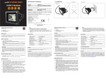
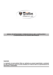
Potentiomètre EG 0-10V Manuel d'installation
(v.02/03)
1) Définition
La série TACn2 permet une variation du débit à l’aide d’un signal 0-10V (mode LS). La position 0 permet
l'arrêt du ventilateur sans nécessiter de couper l'alimentation électrique (softstop).
2) Raccordement
Le potentiomètre 0-10V doit être raccordé au(x) boîtier(s) de commande TACn2 selon les schémas 1 et 2.
3) Données techniques
Nombre maximum de ventilateurs par pot. 0-10V: 10.
Distance totale de raccordement : maximum 100 m (le câble doit être faradisé).
Conformité: approuvé CE.
_____________________________________________________________________________________
EG 0-10V potentiometer Installatie-handleiding (v.02/03)
1) Beschrijving
De serie TACn2 laat een selectie op afstand van het debiet door middel van een 0-10V signaal toe (mode
LS). De 0 positie laat toe de ventilator te stoppen zonder de stroom te onderbreken (softstop).
2) Aansluiting
Het 0-10V potentiometer moet verbonden zijn met de aansluitdoos TACn2 volgens schema’s 1 en 2.
3) Technische gegevens
Maximum aantal ventilatoren per Pot. 0-10V: 10.
Totale afstand van de aansluiting: maximum 100 m (kabel moet gefaradizeerd zijn).
Gelijkvormigheid: goedgekeurd CE.
_____________________________________________________________________________________
EG 0-10V potentiometer Installation manual
(v.02/03)
1) Scope
The TACn2 fans allow external airflow selection using a 0-10V signal (LS mode). The 0 position allows to
stop the fan without having to shut the power off (softstop).
2) Wiring
The 0-10V potentiometer has to be connected to the TACn2 control box according to diagrams 1 and 2.
3) Technical data
Maximum fans per 0-10V pot.: 10.
Maximum total wiring distance: 100 m (cable has to be faradized).
Compliance: CE approved.
ANNEXE 1 – BIJLAGE 1 – APPENDIX 1
Schéma de raccordement 1 – Aansluitschema 1 – Wiring diagram 1
FAN 2
FAN 1
1
2
G
G
3
4
5
6
3
4
G
6
G
7
8
1
2
G
G
3
4
5
6
G
7
6
G
7
8
0-10V potentiometer
Schéma de raccordement 2 – Aansluitschema 2 – Wiring diagram 2
FAN 2
FAN 1
1
2
G
G
3
4
5
6
G
7
8
1
2
Softstop/start
6
3
4
G
0-10V potentiometer
G
G
3
4
5
8