1
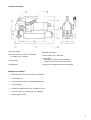
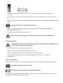
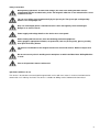
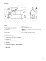
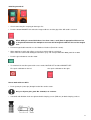
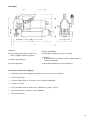
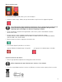
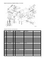
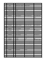
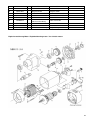
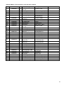
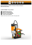
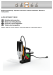
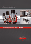
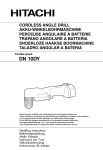
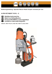
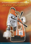
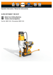
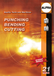
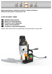
Bedienungsanleitung / Operation Instructions / Manuel d'utilisation /
Manual de instrucciones
ALFRA ROTABEST V32
Winkelbohrmaschine
Angular Metal Core Drilling Machine
Perceuse d’angle pour métaux
Taladro magnético de broca hueca para metal
Artikel Nr. 18710 / Prod.-No. 18710 / N° de produit 18710 / Artículo n.º 18710
Sicherheitshinweise
Bei Bohren an Wänden und Decken muss die Metallkernbohrmaschine durch den mitgelieferten
Sicherheitsgurt abgesichert werden. Die Magnethaftkraft bleibt bei einer Stromunterbrechung
nicht erhalten.
Der ausgebohrte Kern wird automatisch vom Auswerferstift ausgestoßen.
Der Auswerferstift kann bei unsachgemäßer Handhabung brechen.
Nur unbeschädigte Anschlussleitungen und Verlängerungsleitungen verwenden und regelmäßig
auf Beschädigung überprüfen. Sonst besteht die Gefahr eines elektrischen Schlages.
Netzspannung und Spannungsangaben am Gerät müssen übereinstimmen.
Beim Arbeiten mit diesem Gerät folgende Schutzausrüstung tragen:
Schutzbrille, festes Schuhwerk, Gehörschutz, Haarnetz (bei langen Haaren), Handschuhe, ggf.
auch Schürze und Helm.
Die Aufstellfläche für den Magnetfuß muss eben, sauber und rostfrei sein. Lack- und
Spachtelschichten entfernen.
Keine Elektro-Schweißarbeiten an dem Werkstück ausführen, auf dem die
Metallkernbohrmaschine zum Einsatz kommt.
Vor allen Arbeiten Kühlmitteldruckflasche montieren.
Bestimmungsgemäße Verwendung
Dieses Gerät ist bestimmt zum Bohren mit Kernbohrern in wettergeschützter Umgebung, von Materialien mit
magnetisierbarer Oberfläche. Es ist bestimmt für den gewerblichen Einsatz in Industrie und Handwerk. Das Gerät
lässt sich waagrecht, senkrecht und über Kopf einsetzen.
2
Technische Daten
Artikel – Nr.:
18710
Bezeichnung:
ALFRA Rotabest Winkelbohrmaschine V 32
Leistungsaufnahme:
900 Watt
Lastdrehzahl:
450 -min
Werkzeugaufnahme:
19 mm Weldon
Kühlmittelzufuhr:
integriert, automatisch von oben durch die Spindel
Spannung:
230 V
Magnethaftkraft:
16000 N
Bohrleistung Kernbohrer:
12 – 32 mm
Schnitttiefe:
25 mm
Einsatzhöhe:
227 / 1895 mm
Magnetfußgröße:
90 x 200 mm (starr)
Gewicht
12,5 kg
1
3
Gerätebeschreibung
A) Antriebsmotor
B) Ratschenschlüssel für Vor- / Rückhub,
verstellbar rechts und links
C) Bedienfeld
D) Magnetfuß
E) Weldon Aufnahme
F) Zahnstangen Vor- / Rückhub
G) Tragegriff,
durch Entfernen kann die Gesamthöhe
nochmals auf 185 mm reduziert werden.
H) Anschluss für Kühlmittelschlauch beweglich
Mitgeliefertes Zubehör
• 1 Kühlmittel-Druckflasche mit Schlauch und Nippel
• 1 Transportkasten
• 1 Innensechskantschlüssel für Weldonaufnahmen
• 1 Sicherheitsgurt
• 1 HSS Co Kernbohrer Ø 18 mm, Schnitttiefe 25 mm
• 1 Auswerferstift 6.35 x 70 mm (Art.-Nr. 1924500)
• 1 Bedienungsanleitung
4
Ein- und Ausschalten
• Zuerst Kabel und Stecker auf Beschädigung prüfen!
• Die rote Taste MAGNET ON betätigen, damit der Magnet haftet und der Halt des Bohrständers gewährleistet
wird.
Beim Bohren von Materialstärken unter 6 mm muss eine Stahlplatte entsprechender Stärke
unter das zu bearbeitende Werkstück gelegt werden, damit der Magnetfuß seine volle
Magnethaftkraft entfalten kann.
• Für die nicht magnetisierbaren Materialien verwenden Sie bitte die Rotabest Vacubest Vakuumanlage
(Artikel -Nr. 18150).
• Bei Arbeiten an Wänden und Decken die Bohreinheit mit Sicherheitsgurt sichern.
Wir empfehlen bei diesen Arbeiten das Kühlen durch ein Spray (Alfra BIO 4000, Artikel Nr. 21040).
• Den Antriebsmotor durch Betätigen der grünen Taste einschalten.
• Das Ausschalten erfolgt in umgekehrter Reihenfolge:
Zuerst die rote Taste links betätigen,
dann rote Taste rechts betätigen
Arbeiten mit Kernbohrer
• Auswerferstift (Zentrierstift) durch den Kernbohrerkopf schieben.
Nur Auswerferstifte 6,35 x 70 mm, Art.-Nr. 1924500, verwenden.
• Kernbohrer mit Weldonschaft, werden mit den Klemmschrauben DIN 913 auf den beiden Spannflächen
festgespannt.
.
5
• Zuerst den Kernbohrer mit Auswerferstift auf einen angekörnten Punkt oder Anriss ausrichten und
aufsetzen.
• Den Kernbohrer aufsetzten und Werkstück anbohren bis die ganze Schnittfläche als Kreisring ausgebildet
ist.
• Während des Bohrvorgangs den Kernbohrer mittels Kühlmitteldruckflasche und geeignetem Kühlmittel ständig
kühlen.
Kühlmittelflüssigkeit vom Schaltkasten fernhalten.
• Während des Bohrens den Antriebsmotor nicht abschalten. Nach dem Bohrvorgang Kernbohrer bei
laufendem Motor zurückziehen.
• Nach jedem Bohren Späne und Kern entfernen.
Späne mit Spänehaken entfernen. Nicht mit bloßer Hand anfassen. Verletzungsgefahr!
Reinigen und Pflegen
Vor Pflegearbeiten immer zuerst den Netzstecker ziehen, sonst droht Verletzungsgefahr durch
unbeabsichtigtes Einschalten der Maschine.
• Anschlussleitungen auf Beschädigungen kontrollieren.
• Seitliche Führungs-Zahnstangen regelmäßig reinigen und ölen.
• Nach ca. 250 Betriebsstunden sollten die Kohlebürsten ausgetauscht werden.
• Nach Arbeitsbeendigung empfehlen wir, die Metallkernbohrmaschine in dem Transportkoffer
aufzubewahren.
Warten und Reparieren
Warten, prüfen und reparieren dürfen nur Elektrofachkräfte nach den im jeweiligen Land gültigen Vorschriften.
Nur Original ALFRA Ersatzteile verwenden.
Ersatzteilübersicht am Ende dieser Bedienungsanleitung.
Die Metallkernbohrmaschinen ALFRA ROTABEST sollten nach ca. 250 Betriebsstunden von unserer ALFRA
Werkstatt oder Vertragspartnern gewartet werden.
6
EG-Konformitätserklärung
Wir
Alfred Raith GmbH
2. Industriestr. 10
68766 Hockenheim
erklären in alleiniger Verantwortung, dass die Metallkernbohrmaschine
ALFRA Rotabest V32
folgenden Richtlinien entspricht:
Maschinenrichtlinie
Niederspannungsrichtlinie
Elektromagnetische Verträglichkeit (EMV)
2006/42/EG
2006/95/EG
2004/108/EG
Folgende Normen oder normative Dokumente wurden angewandt:
EMV- Richtlinie:
EN 55014-1:2006
EN 55014-2:1997+A1:2001
EN 61000-3-2:2006
EN 61003-3-3:1995+A1:2001+A2:2005
Dokumentationsbeauftragte:
Cornelia Dorn
Hockenheim, 27.02.2011
Markus A. Döring
(Geschäftsführer)
7
Safety instructions
During drilling operations on walls and ceilings, the metal core drilling machine must be
safeguarded with the included safety chain. The magnetic adhesion is not maintained in case of
a failure of circuit.
The cut core will be ejected automatically by the ejector pin. The ejector pin could possibly
break in case of improper use.
Only use undamaged power cord and extension cords and regularly check on damages.
Danger of an electric shock!
Power supply and voltage details at the device must correspond.
When working with this device, wear the following protection equipment:
Safety goggles, appropriate footwear, ear protection, hair net (for long hair), gloves, possibly
also apron and safety helmet.
The place of installation for the magnet foot must be clean and rustfree. Remove lacquer and
filler.
Do not execute any electric welding on the workpiece on which the Metal Core Drilling Machine
is used.
Prior to all operations mount coolant unit.
Specified conditions of use
This device is destined to cut material with magnetisable surface with core cutters in sheltered environment for
commercial use in industry and craft. The device is suitable for drilling vertical, horizontal and overhead.
8
Technical Data
Prod. – No.:
18710
Name:
ALFRA Rotabest Angular Metal Core Drilling Machine V 32
Input:
900 Watt
Load rpm:
450 rpm
Tool holder:
19 mm Weldon
Coolant supply:
internal, automatically through the spindle
Voltage:
230 V
Magnetic Adhesion:
16000 N
Drilling performance core drills:
12 – 32 mm
Cutting Depth:
25 mm
Operational range:
227 / 1895 mm
Size of Magnet Foot:
90 x 200 mm (rigid)
Weight:
12,5 kg
9
Description
A) Motor
E) Weldon shank
B) ratched wrench for pre and return
stroke, adjustable left and right
F) rack for pre and return stroke
C) Control panel
G) Handle
by taking off the handle the total height can be reduced
to 185 mm
D) Magnet foot
H) Connection for coolant hose, movable
Standard scope of supply
• 1 coolant pressure bottle with hose and nipple
• 1 Transport case
• 1 allen wrench for weldon tool holder
• 1 Safety Belt
• 1 HSS Co core drill Ø 18 mm, cutting depth 25 mm
• 1 ejector pin 6.35 x 70 mm (art.-no. 1924500)
• 1 Manual Book
10
Switching on and off
• Check connecting line and plug on damages first.
• Push the button MAGNET ON so that the magnet adheres and the grip of the drill stand is ensured.
When drilling in a material thickness less than 6 mm, a steel plate of appropriate thickness has
to be placed underneath the workpiece to ensure the full magnetic adhesive force of the magnet
foot.
• For non-magnetisable materials use the Rotabest Vacubest (Prod.-No. 18150).
• When working on walls and ceilings secure the machine with the safety belt.
At this work we recommend cooling the tool with a spray. For example Alfra BIO 4000, prod. No. 21040.
• Push the green button to start the motor.
• To switch off the machine proceed in reverse order, MOTOR OFF and then MAGNET OFF.
First push red button on the left
then push red button on the right
How to work with core drills
• Push ejector pin (center pin) through head of the annular cutter.
Only use injector pins, prod. No. 1924500, 6.35 x 70 mm.
• Core drills with Weldon shank are tightened with clamping screws (DIN 913) on both clamping surfaces.
11
• First place core drill with ejector pin on a marked centre or marking.
• Set the cutter and spot-drill, until the entire cut edge is formed as a circle.
• During the drilling process, cool the core drill permanently using the coolant pressure bottle and suitable
coolant.
Keep coolant fluid away from switch box.
• Do not switch off the motor during drilling . Pull back the core drill with running motor after the drilling process .
• Remove chips and core after each drilling.
Remove chips with Chip-Remover. Do not touch with bare hands. Danger of injury!
Cleaning and care
Pull plug prior to cleaning. Danger of injury by unintentional switching on.
• Check connecting lines on damages.
• Clean and oil side guide racks regularly.
• Carbon brushes should be replaced after appr. 250 hours running time.
• After the work is finished we recommend to store the metal core drilling machine in the transport case.
Maintenance and repair
Maintenance, checks and repairs are only to be made by electronic specialists according to the valid regulations of
the respective country.
Only use genuine ALFRA spare parts.
Spare part list at the end of this operation manual.
The metal core drilling machine Alfra Rotabest should be serviced after appr. 250 hours running time by our Alfra
workshop or appointed dealers.
12
CE Declaration of Conformity
Herewith we
Alfred Raith GmbH
2. Industrie Str. 10
68766 Hockenheim
declare that the Metal Core Drilling Machine
ALFRA Rotabest V32
corresponds to the following standards:
Machine standard: 2006/42/EG
Low voltage standard: 2006/95/EG
Electro-magnetic compatibility (EMC): 2004/108/EG
Following standards or standard documents were applied:
EMC- standard:
EN 55014-1:2006
EN 55014-2:1997+A1:2001
EN 61000-3-2:2006
EN 61003-3-3:1995+A1:2001+A2:2005
Documentation:
Cornelia Dorn
Hockenheim, 27.02.2011
Markus A. Döring
(Managing Director)
13
Consignes de sécurité
Pendant des travaux de perçage sur murs ou plafonds, l’appareil doit être impérativement
maintenu avec la chaîne de sécurité fournie avec la machine car l’appareil perd son adhérence
magnétique dès que l’alimentation en courant est interrompue.
La tige d’éjection libère automatiquement la débouchure.
Si la tige est mal utilisée, elle peut casser.
Assurez vous que les fiches, prises et fils électriques que vous utilisez sont en bon état. Vérifiez
les régulièrement.
La tension du réseau d’alimentation électrique doit être identique avec celle de la machine.
Pendant les travaux avec cette machine, nous recommandons à ses utilisateurs de porter des
lunettes de sécurité, des chaussures adéquates, une protection accoustique, une protection
pour les cheveux (surtout s’ils sont longs), gants, un casque et une blouse de travail.
La surface où le socle magnétique sera posé doit être plane, propre et sans rouille. Éliminez les
couches de peinture ou de mastic auparavant.
Ne faites en aucun cas des travaux d’électro-soudure sur l’élément sur lequel la perceuse sera
employée.
Avant tous travaux, fixer la bouteille de pression du liquide de refroidissement.
Conditions d’utilisation
Cet appareil est conçu pour des travaux de caractère industriel ou artisanal, dans un endroit protégé des
intempéries, pour percer des trous avec des fraises à carotter dans des matériaux dont la surface est
magnétisable. Il peut être utilisé horizontalement, verticalement ou à bras levés.
14
Détails techniques
Nro. d’article:
18710
Description:
Rotabest perceuse d’angle V32
Puissance:
900 Watt
Vitesse sous charge:
450 -min
Raccordement d’outil:
19 mm Weldon
Alimentation en lubrifiant:
intégrée dans le système
Tension:
230 V 50/60 Hz
Adhérence magnétique:
16000 N
1
Diamètre de perçage maximum
- fraises à carotter:
12 - 32 mm
Profondeur de coupe:
25 mm
Hauteur d’action:
227 / 1895 mm
Dimensions du
socle magnétique:
90 x 200 mm
Poids:
12,5 kg
15
Description
A) Moteur
B) Clé ä cliquet pour précourse/course de
retour, réglable ä droite et ä gauche
C) Tableau de commande
D) Socle magnétique
E) Porte-outil Weldon
F) Crémaillère de précourse/course de retour
G) Poignée
de manutention, peut réduire encore la hauteur totale ä
185 mm si démontée.
H) Raccord amovible pour tuyau ä réfrigérant
Accessoires fournis avec l’appareil
• 1 bouteille de pression du liquide de refroidissement avec tuyau et raccord fileté
• 1 Caisse de transport
• 1 clé mâle coudée pour vis à six pans creux sur porte-outil Weldon
• 1 sangle de sécurité
• 1 fraise à carotter HSS-Co de Ø 18 mm, profondeur de coupe : 25 mm
• 1 tige d’éjection 6,35 x 70 mm (n° d’art. 1924500)
• 1 Manuel d‘utilisation
16
Mise en marche et arrêt
• Assurez vous du bon état des fiches, prises et fils électriques.
• Actionner la touche rouge à droite, afin que l’aimant adhère et que la tenue du support soit garantie.
Lors du perçage de matières d’épaisseur inférieure à 6 mm, il convient de poser au-dessous de
la pièce à usiner une plaque de tôle d’acier d’épaisseur correspondante, afin que le socle
magnétique puisse développer son adhérence magnétique complète.
• Si vous travaillez des matériaux non magnétisables, utilisez notre système à vide Rotabest Vacubest
(Nro. d’article 18150).
• Pour des travaux sur murs et plafonds, attachez la perceuse avec la chaîne de sécurité.
Pour des travaux sur murs et plafonds nous conseillons le refroidissement avec une bombe de lubrifiant
(Alfra BIO 4000 – Nro. d’article 21040)
• Mettre le moteur en marche en appuyant sur la touche verte.
• Pour éteindre l’appareil, procéder en sens inverse:
appuyez d’abord sur le bouton rouge sur la gauche
puis appuyez sur le bouton rouge sur la droite.
Pour des travaux avec des fraises
• Placer la tige d’éjection (ou pointeau de centrage) dans la tête de la fraise.
Utiliser uniquement des tiges d’éjection 6,35 x 70 mm, n° d’art. 1924500
• Les fraises à tige Weldon sont fixées avec des vis (DIN 913) sur les deux surfaces plates prévues à cet effet.
17
• Tout d’abord placer la fraise avec la pointe de centrage et la tige d’éjection sur un point déjà amorcé au
pointeau ou fissuré.
• Placer la fraise et percer la pièce de travail jusqu’à ce que toute la surface à couper soit amorcée.
• Pendant le processus de forage, constamment refroidir la fraise par bouteille de pression du liquide de
refroidissement et un refroidissement approprié.
Conserver le réfrigérant hors de portée du coffret de commande.
• Ne pas arrêter le moteur pendant le perçage. Une fois le perçage terminé, retirez la fraise pendant que le
moteur est encore en marche.
• Après chaque opération de perçage, retirer la débouchure et les copeaux.
Ne jamais essayer de les enlever avec les doigts. Danger de blessure !
Nettoyage et entretien
Débranchez l’appareil avant tout nettoyage de l’appareil.
• Contrôler l’état du fil d’alimentation électrique.
• Nettoyer et huiler régulièrement les crémaillères de guidage.
• Les charbons doivent être changés après environ 250 heures d’emploi de la machine.
• Nous recommandons de stocker la perceuse dans la malette de transport après l’emploi.
Révision et réparation
Seuls les électrotechniciens sont aptes à contrôler, réviser ou réparer ces appareils en respectant les directives
valides appliquées dans leur pays.
Utilisez exclusivement les pièces de rechange de la marque ALFRA.
Voir la liste des pièces détachées à la fin de cette notice d’emploi.
Après environ 250 heures de travail les perceuses Alfra Rotabest doivent être révisées à l’atelier ALFRA ou par un
atelier agréé par ALFRA.
18
Déclaration de Conformité CE
Nous
Alfred Raith GmbH
2. Industriestr. 10
D - 68766 Hockenheim
déclarons que la perceuse
ALFRA Rotabest V32
correspond aux recommandations suivantes :
Recommandations de la machine: 2006/42/EG
Recommandations de la basse tension: 2006/95/EG
Compatibilité électromagnétique: 2004/108/EG
Les normes ou documents normatifs suivants ont été appliqués:
Compatibilité électromagnétique:
EN 55014-1:2006
EN 55014-2:1997+A1:2001
EN 61000-3-2:2006
EN 61003-3-3:1995+A1:2001+A2:2005
Chargé de la documentation:
Cornelia Dorn
Hockenheim, 26.11.2012
Markus A. Döring
(Directeur)
19
Explosionszeichnung / Exploded drawing / Vue éclatée
Stückliste / Parts list / Liste des pieces
Pos.
Art.-Nr.
St.
Beschreibung
Description
01
189201001
1
Gehäuse
housing
02
03
189201002
1
Bügel
bail
189201003
1
Sockel
socket
04
189411028
1
Magnetfuß
magnet food
06
189201004
1
Getriebewelle
shaft
07
189201005
1
Keilwelle
spline shaft
08
189201006
1
Welle 4kt 3/8"
arbor
09
189201007
1
Kühlmittelrohr
cooling unit tube
Kühlmittelrohr
cooling unit tube
05
189201007B
10
189201008
1
Hülse 4kt 3/8"
bushing
11
189201009
2
Stift
set screw
189201010
1
Kegelrad 1
pnion
15
189201011
2
Zahnrad
gear
16
189201012
2
Zahnstange
rack
17
189201013
1
Grundblech
base plate
18
189201014
1
Blechhaube
plate
19
189201015
2
Deckungsblech 1
cover plate 1
20
189201016
1
Deckungsblech 2
cover plate 2
12
13
14
21
20
22
189201017
1
Handgriff
handle
24
18215
1
Bohrmaschine 230 Volt
drilling machine
25
18215.110
Bohrmaschine 110 Volt
drilling machine
23
26
27
189201018
1
Druckfeder 2
pressure spring 2
28
189201019
1
Kolben
cock
29
189201020
1
Scheibe
disc
31
189201021
2
Gleitlager
bushing bearing
32
189201022
1
Rillenkugellager
grooved ball bearing
DIN 625-6001 2RSR
33
189201023
1
Rillenkugellager
grooved ball bearing
34
189201024
1
Rillenkugellager
grooved ball bearing
35
189160416
1
Spannstift
dowel pin
DIN 625-6004 2RSR
DIN 625-61805
2RSR
DIN 1481-4x16
36
189120410
1
Zylinderschraube
cylinder head screw
DIN 84-M4x10-Ms
37
189140308
10
Linsenschraube
lens head srew
ISO 7380-M3x8
38
189140512
2
Zylinderschraube
cylinder head screw
DIN 7984-M5x12-8.8
39
189010516
2
Zylinderschraube
cylinder head screw
DIN 912-M5x16-8.8
40
189010620
6
Zylinderschraube
cylinder head screw
DIN 912-M6x20-8.8
41
189010630
3
Zylinderschraube
cylinder head screw
DIN 912-M6x30-8.8
42
189010650
3
Zylinderschraube
cylinder head screw
DIN 912-M6x50-8.8
43
189621036
2
Gewindestift
set screw
44
189090410
5
Linsenschraube
lens head srew
45
189060006
11
Federring
lock washer
DIN 913-M8x8-45H
ISO 7380-M4x1010.9
DIN 7980-B6-FSt
46
189060005
2
Federring
lock washer
DIN 7980-B5-FSt
47
189201025
1
Sicherungsring
circlip
DIN 471-25x1.2
48
189621037
1
Sicherungsring
circlip
DIN 472-19x1
49
189201026
2
Sicherungsring
circlip
DIN 472-42x1.75
50
189311011
1
KUPFERRING
copper ring
19x13x1-Cu
51
189201027
1
O-Ring
o-ring
52
189201028
2
O-Ring
o-ring
53
189080006
1
Scheibe
disc
DIN 3770-7x2-NBR
DIN 3770-17x3.5NBR
DIN 125-A6.4-140HV
54
189201029
2
Zylinderstift
cylinder shaft
DIN 7-2m6x6-St50K
55
189201030
1
Federndes Druckstück
resilient thrust piece
GN 615-M4-K-PFB
56
189201031
1
Federndes Druckstück
resilient thrust piece
GN 615-M6-K-PFB
58
189201032
1
Durchsführungstülle
grommet
DK-PVC 6/9/12-2
59
189480018
1
Sechskant-Stiftschlüssel
hexagon wrench key
DIN 911-4
60
189201033
1
Umschaltknarre 4kt 3/8"
ratchet wrench
61
189490602
1
Kabelverschraubung
cable connexion
62
189490601
1
Gegenmutter
locknut
63
189480276
1
Anschlussleitung Euro
supply cable Euro
189480276GB
Anschlussleitung GB
supply cable GB
189480276UL
Anschlussleitung UL
supply cable UL
189480276CH
Anschlussleitung CH
supply cable CH
189480276AUS
Anschlussleitung AUS
supply cable AUS
189480276HO
Anschlussleitung HO
supply cable HO
30
57
21
64
189411057
64
189411057.110
65
189411056
66
189411058
1
Motorschalter 230 Volt
motor switch 230 volt
Motorschalter 110 Volt
motor switch 110 volt
1
Magentschalter
magnet switch
1
Gleichrichter 230 Volt
commutator 230 volt
Gleichrichter 110 Volt
commutator 110 volt
189411058.110
67
68
189490610
1
WinkelKabelverschraubung
cable connexion
189201034
1
Winkel-Verschraubung
angle bolting
69
70
71
Explosionszeichnung Motor / Exploded drawing motor / Vue éclatée moteur
22
Stückliste Motor / Parts list motor / Liste des pieces moteur
Pos.
Art.Nr.
St.
1
189502002
4
2
3
4
189302002
189302003
189302004
1
2
2
Beschreibung
Blechsschrauben
4,8x 50
Motorkappe
Blechschraube 4,2 x1 3
Passcheibe 16/22 x 0,5
5
189812011
1
Rillenkugellager 608 2Z
6
189302006
1
7
8
9
10
189302007
189302008
189302009
189302010
1
1
2
1
11
189502043
2
12
13
189302012
189601017
1
1
14
189601018
1
15
16
17
18
189502056
189302016
189302017
189302018
1
1
1
1
19
189302019
1
20
189302020
1
21
22
23
24
189302054
189302053
189502011
189302024
1
1
1
4
Kondensatorenaufnahme
Federschraube
Drahtformfeder
Kohlebürsten
Feld 230 V
Blechschrauben
3,9 x 60
Luftleitring
Sicherungsring 28/1,2
Rillenkugellager
6001 2Z
Sicherungsring 10/1
Anker 230 V
Spindelrad
Passcheibe 17/24x0,2
Rillenkugellager
6003.2.RS
Rillenkugellager
6904.2RS
Arbeitsspindel
Getriebegehäuse
Steckkerbstift 4x12
Blechschraube 4,8x38
25
189502037
1
Rillenkugellager 608
26
27
28
29
45
46
189302026
189302027
189302028
189302029
189502065
189302051
1
1
1
1
1
1
Zwischenrad
Ritzelwelle
Getriebelagerschild
Motorgehäuse kpl.
Entstörkondensator
Getriebedichtung
Description
screw 4,8 x 50
motor housing, compl.
screw
washer
deep groove ball
bearing 608.2Z
conderser holde
screw for feather
feather
carbon brush
field, compl. 230 V
screw 3,9 x 60
fan shroud
retaining ring
deep groove ball
bearing 6001.2 Z
retaining ring
armature, compl. 230 V
spindel gear
washer
deep groove ball
bearing 6003.2RS
deep groove ball
bearing 6904.2RS
motor spindle
gear box
dowel pin
screw
deep groove ball
bearing 608
gear block 2
pinion shaft
gear box flange
motor housing, compl.
interference capacitor
gear sealing
23
Tel. 06205-3051-0
Fax 06205-3051-150
Internet: www.alfra.de
E-mail: [email protected]
11/2014
Alfred Raith GmbH
2. Industriestr. 10
D-68766 Hockenheim
24