1
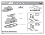
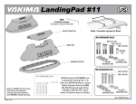
Cap hardware FOR TRACKS
Due to shell thickness variances, mounting bolts are not included with this kit
and need to be purchased separately. Use a stainless steel, buttonhead,
10/32"screw in the desired length.
TOOLS REQUIRED:
power drill
1/8” drill bit
1/4” drill bit
60x
84x
84x
IMPORTANT WARNING!
IT IS CRITICAL THAT ALL YAKIMA RACKS AND ACCESSORIES BE PROPERLY AND SECURELY ATTACHED TO YOUR VEHICLE.
IMPROPER ATTACHMENT COULD RESULT IN AN AUTOMOBILE ACCIDENT, AND COULD CAUSE SERIOUS BODILY INJURY OR
DEATH TO YOU OR TO OTHERS. YOU ARE RESPONSIBLE FOR SECURING THE RACKS AND ACCESSORIES TO YOUR CAR,
CHECKING THE ATTACHMENTS PRIOR TO USE, AND PERIODICALLY INSPECTING THE PRODUCTS FOR ADJUSTMENT, WEAR,
AND DAMAGE. THEREFORE, YOU MUST READ AND UNDERSTAND ALL OF THE INSTRUCTIONS AND CAUTIONS SUPPLIED
WITH YOUR YAKIMA PRODUCT PRIOR TO INSTALLATION OR USE. IF YOU DO NOT UNDERSTAND ALL OF THE INSTRUCTIONS
AND CAUTIONS, OR IF YOU HAVE NO MECHANICAL EXPERIENCE AND ARE NOT THOROUGHLY FAMILIAR WITH THE
INSTALLATION PROCEDURES, YOU SHOULD HAVE THE PRODUCT INSTALLED BY A PROFESSIONAL INSTALLER SUCH AS A
QUALIFIED GARAGE OR AUTO BODY SHOP.
Align tracks to each
other and position
track ends equal
distance from rear of
shell.
Using a marker pen,
outline alternate holes
through the track.
Begin with first or last
hole, and skip every
other hole.
CAUTION: Track base can slide.
Be sure it is aligned to the track!
Remove track from shell.
Drill 1/8” pilot holes
in center of marks.
Drill 1/4” into
pilot holes.
Carefully blow
away debris.
NEVER DRILL
THROUGH TRACK!
Part #1032663 Rev A
Place large, white
nylon washer onto
holes to which
silicone has been
applied.
Apply a generous amount of
silicone sealant
into the drilled
holes.
WARNING: Direct contact of uncured sealant irritates eyes
and may irritate skin. Overexposure to vapor may irritate
eyes, nose and throat. Avoid eye and skin contact. Use with
adequate ventilation. Do not handle contact lenses with
sealant on hands. In case of eye contact, flush with water for
15 minutes. Obtain medical attention. In case of skin contact,
remove from skin and flush with water. Sealant releases
acetic acid (vinegar-like odor) during cure.
Slide nut plates from your
tower kit into track
(2 per tower/4 per track).
Note: Washer should be
flat against drilled hole.
Attach end caps before
attaching tracks to roof.
Place track on roof.
Be sure to align
track holes to
holes in base
and in roof.
Install bolts and small black nylon washers into track and into roof.
NOTE: Do not
use these
washers on
bolts at each
end of tracks.
SECOND TRACK INSTALLATION:
If you have not installed the second track,
repeat the entire instruction beginning at step 1.
From inside your shell,
attach the cap nut.
Tighten the
bolts through
the track from
above.
A helpful
friend will
make this
easier.
Load limits are determined by
shell roof strength. Contact your
shell manufacturer for details.
Some deflection may occur with
any significant load.
Serious off-highway driving
may also cause deflection.
LIMITED WARRANTY
Yakima Products (“Yakima”) will repair or replace merchandise which proves defective in materials and/or workmanship. The limited warranty is effective for
three years from the date of purchase. The limited warranty is applicable only if the Fit List and instructions are followed and the products are used properly. If a
customer believes that a Yakima product is defective, the customer must return it to an authorized Yakima dealer with proof of purchase. Yakima will then issue
authorization to the dealer for the return of these products. If an article is found to be defective upon inspection by Yakima, Yakima will repair or replace the
defective article at its discretion without charge. The customer will pay freight to Yakima, and Yakima will pay any applicable return freight. Unauthorized returns
will not be accepted. Normal wear and tear of Yakima products or damage resulting from misuse, accidents, or alterations are not covered by this Limited
Warranty.The purchaser acknowledges that Yakima has no control over the attachment of its products to vehicles or the attachment of items to the Yakima
products. Accordingly, Yakima cannot assume responsibility for any damage to any property arising out of the improper attachment or use of its products. In
addition, this Limited Warranty applies only to Yakima products and not to other products used in conjunction with Yakima products. This Limited Warranty is in lieu
of all other warranties, expressed or implied, and does not cover consequential damages of any kind that may arise from the use or misuse of any Yakima product.
Tracks
TOOLS REQUIRED:
adjustable end wrench
1/2" wrench
1/8" Allen wrench
center punch
hammer
electric drill
1/8" drill bit
9/32" drill bit
Part #1030988 Rev.C touch-up paint
ATTENTION INSTALLERS:
If you will be installing tracks on several vehicles,
call for information on industrial grade installation tools.
YAKIMA CUSTOMER SERVICE: 888-925-4621
REFER TO THE
TRACK FIT SHEET
for track placement
and important details
about your vehicle!
Punch center of mark
for drilling.
Remove track.
Outline rear hole through track.
Align tracks and position
track ends according to
information in the
track fit sheet.
Track base is loose and can slide.
Be sure it is aligned to track.
DO NOT DRILL DEEPER THAN 1/4". Use a drill
stop to prevent drilling through vehicle’s interior
liner. If you do not have a stop, use tape and
mark bit 1/4" from tip.
Wear goggles
when drilling!
Drill
1/8"
pilot hole
Drill 9/32" hole
Carefully blow
away debris
Attach
soft rubber
washers
onto
Plusnuts®.
Note: Washer
should be flat
against
Plusnut® head.
Attach Plusnut®
and washer
to tool
as shown.
Attach nut
with washer
onto
Plusnut®
tool.
Set
into hole.
Tighten nut on tool using
1/2" wrench and adjustable
end or 7/16" wrench.
Seal edges
of hole with
enamel base
paint.
Allow to dry.
Remove flaring tool:
Use adjustable end \wrench
to unscrew post from Plusnut®.
Reassemble tool
for next Plusnut®.
Place track on roof
aligning hole.
Outline front hole.
Install bolt
loosely.
Pivot the track
to install front Plusnut®
Loosen bolt if necessary.
Center punch, pilot, drill, clear, seal, install Plusnut® INTO FRONT HOLE.
(Steps 4 through 10)
Install front bolt
through track into
Plusnut®.
Never
punch or drill
through track.
Loosen bolts and remove track
from vehicle.
READ YOUR TRACK FIT SHEET
for your vehicle’s
correct drilling points.
Carefully mark and drill only the correct
holes for your specific vehicle.
Center punch, pilot, drill, clear, seal, install
Plusnuts® (Steps 4 through 10).
Slide nut plates from your tower kit into
track (2 per tower /4 per track).
Apply a generous amount of silicone
sealant into the Plusnut® opening.
With track on car, attach bolts and hard washers
through track into Plusnuts®.
Do not use washers
on bolts at each end
of tracks.
Attach end caps before attaching tracks to roof.
NOTE: There may be extra Plusnuts®
because not all holes in the tracks will be used.
WARNING: Direct contact of uncured sealant irritates
eyes and may irritate skin. Over exposure to vapor may
irritate eyes, nose and throat. Avoid eye and skin
contact. Use with adequate ventilation. Do not handle
contact lenses with sealant on hands. In case of eye
contact, flush with water for 15 minutes. Obtain medical
attention. In case of skin contact, remove from skin and
flush with water. Sealant releases acetic acid (vinegarlike odor) during cure.
SECOND
TRACK
INSTALLATION:
Repeat entire
instruction
beginning at
Congratulations!
Install your towers
& mount your
accessories for your
next sporting
adventure!
Landing Pad #1
Refer to YAKIMA Control Tower instructions for important warning and load limitations, and YAKIMA’s limited warranty.
You may need to remove
your vehicle’s factory
crossbars and slats.
Check to see if Landing
Pad location will cause
interference. Refer to
your vehicle’s owner’s
manual for details on
factory rack removal.
RECOMMENDED TOOL:
Measuring Tape
Remove covers from
Landing Pads.
Use existing nut-plates
when possible. Four per
track are required.
FIT NOTE:
INFINITI QX4
1997 to 2002
4dr
NISSAN Pathfinder 4dr
1997 to 2002
• Factory crossbars or
accessories may need to be
removed.
• IF THERE ARE FEWER than 4
plates per track, install
additional plates.
1033028A-1/6
If you need to install additional plates, you
may need to remove end cap.
NOTE: Refer to vehicle owner’s manual for
details on end cap removal.
• Loosen screw
• Remove cap.
You must use
existing plates.
Remove factory crossbars
and slats.
Part #1033028 Rev A
Position the plates for best fit
inside the tracks.
Replace end caps.
Install screw with washer
and spacer into pad.
Align screws in Landing
Pads with plates.
or
NOTE:
If screws seem too short and
are not engaging the plate,
take out screw, remove plastic
spacer, use washer only.
Engage the screw with
wrench supplied. Do not
fully tighten.
In some cases, it may
be easier to assemble
plates, screws, and
bases before sliding
onto tracks.
NOTE:
Do not fully tighten.
Final adjustments will be
made after Control
Tower is installed.
USE CAUTION WHEN
OPENING YOUR HATCH.
Installation Tips:
CROSSBAR SPREAD:
LOAD LOCATION:
The distance between the Yakima
crossbars is determined by the
accessories you wish to carry.
For ease of loading, consider where the
most convenient placement of your load
would be before completing the
installation.
The Crossbar Spread Table (Fit List or
Catalog) will tell you how much crossbar
spread your accessories require.
Arrange Landing Pads on the tracks in the
approximate positions where Control Towers
will be attached.
On some vehicles, hatch
interference with
accessories is unavoidable.
YOU ARE NOW READY TO PROCEED TO CONTROL TOWER INSTRUCTIONS.
1033028A-2/6
Landing Pad #1
On trouvera dans les instructions accompagnant les pieds Control Tower de YAKIMA des avertissements importants et les
limites de charge, en plus de la garantie limitée YAKIMA.
Il faudra peut-être
enlever les barres
transversales et les lattes
du porte-bagages
d’origine. Vérifier si
l’emplacement des
patins Landing Pad
gênera. Consulter le
manuel d’utilisation du
véhicule pour savoir
comment enlever le
porte-bagages d’origine.
OUTIL RECOMMANDÉ:
Ruban à mesurer
Enlever le cache des
patins Landing Pad.
Dans la mesure du possible,
employer les plaquettes filetées
déjà en place. Il en faut quatre
par glissière.
• Il faudra peut-être enlever
les barres transversales ou
des accessoires du portebagages d’origine.
• S’IL Y A MOINS de 4
plaquettes par glissière, en
ajouter.
1033028A-3/6
NOTE DE MONTAGE:
INFINITI QX4 4 po.
1997 à 2002
NISSAN Pathfinder 4 po.
1997 à 2002
Il faut obligatoirement
employer les plaquettes déjà
en place. Enlever les barres
transversales et les lattes du
porte-bagages d’origine.
S’il faut poser des plaquettes supplémentaires,
il faudra peut-être enlever la garniture
d’extrémité des glissières.
REMARQUE: consulter le manuel d’utilisation du
véhicule pour savoir comment enlever les garnitures
d’extrémité des glissières.
• Desserrer la vis.
• Enlever la
garniture d’extrémité.
Part #1033028 Rev A
Mettre les plaquettes dans le sens
où elles s’adaptent le mieux dans
la glissière.
Remettre en place les
garnitures d’extrémité des
glissières.
Enfiler les vis, avec une
rondelle et une entretoise,
dans les patins.
Aligner les vis des patins
et les plaquettes.
ou
REMARQUE: si les vis semblent
trop courtes pour s’engager
dans les plaquettes, sortir les
vis, enlever l’entretoise en
plastique et ne garder que la
rondelle.
Placer les patins sur les glissières à la
position approximative où l’on posera les
pieds Control Tower.
Serrer les vis un peu
plus avec la clé fournie.
Ne pas serrer
complètement.
Dans certains cas, il est
plus facile d’assembler
les plaquettes, les vis
et les patins avant de
les enfiler sur les
glissières.
REMARQUE: ne pas serrer
complètement. On pourra faire le
positionnement définitif au moment de
la pose des pieds Control Tower.
FAIRE ATTENTION EN
OUVRANT LE HAYON.
Conseils de montage:
DISTANCE ENTRE LES
BARRES TRANSVERSALES:
La distance entre les barres transversales
Yakima dépend des accessoires que l’on
compte installer.
On trouvera la distance nécessaire pour
chaque accessoire dans la Table des
distances entre les barres transversales
(“Crossbar Spread Table”), la liste de
compatibilité (“Fit List”) ou le catalogue.
POSITION DE LA CHARGE:
Pour faciliter le chargement,
Sur certains véhicules, le
hayon peut toucher aux
accessoires.
déterminer quel endroit sera le plus
pratique pour la charge, avant
d’achever l’installation.
ON PEUT MAINTENANT PASSER AU MONTAGE DES PIEDS CONTROL TOWER.
1033028A-4/6
Landing Pad #1
Consulte las instrucciones de los soportes Control Tower Yakima por advertencias importantes,
limitaciones de carga y garantía limitada YAKIMA.
!Quizá deba quitar los
travesaños y listones de
fábrica del vehículo.
Verifique si la ubicación
de las Landing Pad
provoca interferencia.
Consulte el manual de
propietario de su
vehículo sobre cómo
retirar la parrilla de
fábrica.
HERRAMIENTA
RECOMENDADA:
Cinta de medir
Quite las cubiertas
de las Landing Pad.
Use las plaquetas - tuerca
existentes cuando sea
posible. Se necesitan cuatro
por riel.
NOTA DE COMPATIBILIDAD
INFINITI 4X4 4dr
1997 a 2002
NISSAN Pathfinder 4dr
1997 a 2002
• Quizá deba quitar los
travesaños o accesorios de
fábrica.
• SI HAY MENOS de cuatro
plaquetas por riel, instale
plaquetas adicionales.
1033028A-5/6
Si tiene que instalar plaquetas adicionales,
quizá deba quitar el capuchón de extremo.
NOTA: Consulte el manual de propietario
del vehículo sobre cómo quitar el
capuchón de extremo.
•
Afloje el tornillo.
•
Quite el capuchón.
Debe usar las plaquetas
existentes.
Quite los travesaños y
listones de fábrica.
Part #1033028 Rev A
Coloque las plaquetas del
mejor modo en los rieles.
Vuelva a colocar los
capuchones de extremo.
Instale un tornillo con
arandela y espaciador en la
Landing Pad.
Haga corresponder los
tornillos de las Landing
Pad con las plaquetas.
o
NOTA:
Si los tornillos parecen
demasiado cortos y no llegan a
la plaqueta, quite el tornillo,
quite el espaciador plástico y
use solamente la arandela.
Ajuste, pero no
completamente, el
tornillo con la llave
proporcionada.
NOTA:
No ajuste
completamente. El
ajuste final se hará
después de instalar el
Control Tower.
En algunos casos, será
más fácil montar las
plaquetas, tornillos y
bases antes de
ponerlas en los rieles.
TENGA CUIDADO AL ABRIR LA
PUERTA TRASERA
Datos para instalación:
SEPARACIÓN DE TRAVESAÑOS:
La distancia entre los travesaños Yakima
depende de los accesorios que desee
transportar.
La tabla de separación de travesaños (lista de
compatibilidad o catálogo) le dirá cuánta
separación necesitan sus accesorios.
Ubique las Landing Pad en los rieles en las
posiciones aproximadas en que se colocarán
los soportes Control Tower.
UBICACIÓN DE LA CARGA:
En algunos vehículos, es inevitable
que la puerta trasera interfiera con
los accesorios.
Para facilitar la carga, considere
cuál será la ubicación más
conveniente de la carga antes de
completar la instalación.
AHORA ESTÁ LISTO PARA APLICAR LAS INSTRUCCIONES DE CONTROL TOWER.
1033028A-6/6
Control Towers
Before you begin installation, your vehicle must have Landing Pads installed.
These instructions are
also applicable for
Control Towers sold
in pairs.
TO BEGIN:
Landing Pads are vehicle specific pads and are purchased separately.
Install your Landing Pads before continuing with these instructions.
IMPORTANT WARNING!
IT IS CRITICAL THAT ALL YAKIMA
RACKS AND ACCESSORIES BE
PROPERLY AND SECURELY
ATTACHED TO YOUR VEHICLE.
IMPROPER ATTACHMENT COULD
RESULT IN AN AUTOMOBILE
ACCIDENT, AND COULD CAUSE
SERIOUS BODILY INJURY OR
DEATH TO YOU OR TO OTHERS.
YOU ARE RESPONSIBLE FOR
SECURING THE RACKS AND
ACCESSORIES TO YOUR CAR,
CHECKING THE ATTACHMENTS
PRIOR TO USE, AND
PERIODICALLY INSPECTING THE
PRODUCTS FOR ADJUSTMENT,
WEAR, AND DAMAGE.
THEREFORE, YOU MUST READ
AND UNDERSTAND ALL OF THE
INSTRUCTIONS AND CAUTIONS
SUPPLIED WITH YOUR YAKIMA
PRODUCT PRIOR TO
INSTALLATION OR USE. IF YOU DO
NOT UNDERSTAND ALL OF THE
INSTRUCTIONS AND CAUTIONS,
OR IF YOU HAVE NO
MECHANICAL EXPERIENCE AND
ARE NOT THOROUGHLY FAMILIAR
WITH THE INSTALLATION
PROCEDURES, YOU SHOULD
HAVE THE PRODUCT INSTALLED
BY A PROFESSIONAL INSTALLER
SUCH AS A QUALIFIED GARAGE
OR AUTO BODY SHOP.
Part #1033015 Rev B
1033015B-1/12
To open cover, pry
and pull forward.
Using the wrench provided,
loosen towers.
Slide two towers onto
each crossbar. Do not
tighten.
Be careful to keep the bars horizontal; the loose
towers could slide from the bar and fall.
Push end caps onto the ends of
the crossbars.
SET BARS AND TOWERS ONTO CAR:
Lower Towers onto Landing Pads.
1033015B-2/12
• Open cover to Control Tower
and lower into Landing Pad.
• Control Tower cannot seat
properly into Landing Pad
unless the cover is open.
Installation Tips:
• Measure equal distances
from front towers.
USE CAUTION WHEN
OPENING YOUR HATCH.
CROSSBAR SPREAD:
LOAD LOCATION:
The distance between the Yakima
crossbars is determined by the
accessories you wish to carry.
FOR EASE OF LOADING, CONSIDER
WHERE THE MOST CONVENIENT
PLACEMENT OF YOUR LOAD
WOULD BE BEFORE COMPLETING
THE INSTALLATION.
The Crossbar Spread Table (Fit List or
Catalog) will tell you how much crossbar
spread your accessories require.
If you have not been instructed to fully tighten Landing
Pads, do so now. Tighten hex screws through the slots
in the Control Towers.
Push down and fully tighten Towers.
TEST THE
INSTALLATION:
Push up on bar end to
test installation. Grab
the bar near the towers
and pull back and forth.
IF THE TOWER SLIDES OR CROSSBAR CAN ROTATE, CHECK TOWER FOR
TIGHTNESS AND RETIGHTEN SCREWS.
1033015B-3/12
On some vehicles, hatch
interference with accessories
is unavoidable.
Firmly close covers until both
sides snap.
“SNAP”
SKS® Lock Cores are optional.
Refer to Lock Core instructions for
installation.
IF ANY PART OF an accessory or tower
contacts the factory installed
crossbars, and the factory bars cannot
move out of the way, they must be
removed completely.
BEFORE
DRIVING AWAY:
SECURE FRONT AND REAR OF
LONG LOADS (I.E. BOATS) TO
ENDS OF VEHICLE FOR SAFE
TRANSPORT. FAILURE TO
PERFORM SAFETY CHECKS
BEFORE DRIVING AWAY CAN
RESULT IN PROPERTY DAMAGE,
PERSONAL INJURY, OR DEATH.
LIMITED WARRANTY
TO REMOVE RACKS:
Use caution
• Unlock tower and
open cover.
• Remove rack.
when loading
Use the Landing Pad cover
when the Control
Tower is not in
use.
or unloading
heavy objects.
MAXIMUM WEIGHT
IS SPECIFIC TO YOUR CAR
Refer to your vehicle owner’s manual or
the Fit List at your Yakima Dealer.
REMOVE YOUR
YAKIMA RACK AND
ACCESSORIES
BEFORE ENTERING
ATTACHMENT HARDWARE CAN LOOSEN
OVER TIME. CHECK AND TIGHTEN IF
NECESSARY, BEFORE EACH USE.
AUTOMATIC CAR
WASHES.
KEEP THESE INSTRUCTIONS!
1033015B-4/12
If you need further technical assistance
or replacement parts:
Please contact your dealer or call us at
(888) 925-4621 or
(707) 826-8000, Monday through Friday,
8:00am to 5:00pm Pacific time.
Yakima Products (“Yakima”) will repair or replace
merchandise which proves defective in materials and/
or workmanship. The limited warranty is effective for
three years from the date of purchase. The limited
warranty is applicable only if the Fit List and instructions
are followed and the products are used properly. If a
customer believes that a Yakima product is defective, the
customer must return it to an authorized Yakima dealer
with proof of purchase. Yakima will then issue
authorization to the dealer for the return of these
products. If an article is found to be defective upon
inspection by Yakima, Yakima will repair or replace the
defective article at its discretion without charge. The
customer will pay freight to Yakima, and Yakima will pay
any applicable return freight. Unauthorized returns will
not be accepted. Normal wear and tear of Yakima
products or damage resulting from misuse, accidents,
or alterations are not covered by this Limited
Warranty.The purchaser acknowledges that Yakima has
no control over the attachment of its products to vehicles
or the attachment of items to the Yakima products.
Accordingly, Yakima cannot assume responsibility for any
damage to any property arising out of the improper
attachment or use of its products. In addition, this Limited
Warranty applies only to Yakima products and not to other
products used in conjunction with Yakima products. This
Limited Warranty is in lieu of all other warranties,
expressed or implied, and does not cover consequential
damages of any kind that may arise from the use or
misuse of any Yakima product.
Control Towers
Avant de commencer l’installation, les patins Landing Pad doivent avoir
été posés sur le véhicule.
Ces instructions
s’appliquent aussi aux
pieds Control Towers
vendus à la paire.
POUR COMMENCER:
Les patins Landing Pad sont spécifiques au véhicule et
s’achètent à part. Poser les patins Landing Pad avant
de poursuivre.
1033015B-5/12
AVERTISSEMENT IMPORTANT:
IL EST IMPÉRATIF QUE LES
PORTE-BAGAGES ET LES
ACCESSOIRES YAKIMA SOIENT
CORRECTEMENT ET SOLIDEMENT
FIXÉS AU VÉHICULE. UN
MONTAGE MAL RÉALISÉ
POURRAIT PROVOQUER UN
ACCIDENT D’AUTOMOBILE, QUI
POURRAIT ENTRAÎNER DES
BLESSURES GRAVES OU MÊME
LA MORT, À VOUS OU À
D’AUTRES PERSONNES. VOUS
ÊTES RESPONSABLE DE
L’INSTALLATION DU PORTEBAGAGES ET DES ACCESSOIRES
SUR VOTRE VÉHICULE, D’EN
VÉRIFIER LA SOLIDITÉ AVANT DE
PRENDRE LA ROUTE ET DE LES
INSPECTER RÉGULIÈREMENT
POUR EN CONTRÔLER L’ÉTAT,
L’AJUSTEMENT ET L’USURE.
VOUS DEVEZ DONC LIRE
ATTENTIVEMENT TOUTES LES
INSTRUCTIONS ET TOUS LES
AVERTISSEMENTS
ACCOMPAGNANT VOTRE
PRODUIT YAKIMA AVANT DE
L’INSTALLER ET DE L’UTILISER. SI
VOUS NE COMPRENEZ PAS
TOUTES LES INSTRUCTIONS ET
TOUS LES AVERTISSEMENTS, OU
SI VOUS N’AVEZ PAS DE
COMPÉTENCES EN MÉCANIQUE
ET NE COMPRENEZ PAS
PARFAITEMENT LA MÉTHODE DE
MONTAGE, VOUS DEVRIEZ FAIRE
INSTALLER LE PRODUIT PAR UN
PROFESSIONNEL, COMME UN
MÉCANICIEN OU UN
CARROSSIER COMPÉTENT.
Pour ouvrir le capot, écarter les
côtés et tirer vers soi.
Enfiler deux pieds
sur chaque barre
transversale. Ne
pas serrer.
À l’aide de la clé fournie,
desserrer les pieds.
Faire attention de garder les barres à l’horizontale:
n’étant pas serrés, les pieds pourraient tomber.
Enfoncer les bouchons d’extrémité sur
les bouts des barres.
DÉPOSER LES BARRES ET LES PIEDS SUR LE VÉHICULE:
Déposer les pieds sur les patins.
1033015B-6/12
• Ouvrir le capot du pied et emboîter
le pied dans le patin.
• Le pied ne peut pas s’emboîter
correctement sur le patin si le
capot n’est pas ouvert.
DISTANCE ENTRE LES
BARRES TRANSVERSALES:
Conseils de montage:
• La distance entre les pieds
avant et arrière doit être la
même des deux côtés du
véhicule.
La distance entre les barres
transversales Yakima dépend des
accessoires que l’on compte installer.
On trouvera la distance
nécessaire pour chaque accessoire
dans la Table des distances entre les
barres transversales («Crossbar Spread
Table»), la liste de compatibilité («Fit
List») ou le catalogue.
Serrer complètement les vis
hexagonales en passant la clé à
travers la fente des pieds.
POSITION DE LA CHARGE:
POUR FACILITER LE CHARGEMENT,
DÉTERMINER QUEL ENDROIT SERA
LE PLUS PRATIQUE POUR LA
CHARGE, AVANT D’ACHEVER
L’INSTALLATION.
En poussant vers le bas, finir de
serrer les pieds.
FAIRE ATTENTION EN
OUVRANT LE HAYON.
Sur certains véhicules,
le hayon peut toucher
aux accessoires.
Fermer les capots en les rabattant
en place.
Les serrures SKS® Lock Core sont
vendues en option.
VÉRIFIER LE MONTAGE:
Prendre le bout des barres et
pousser vers le haut. Prendre
les barres près des pieds et
pousser vers l’avant et
l’arrière.
SI LES PIEDS GLISSENT OU SI LES BARRES TRANSVERSALES PEUVENT
TOURNER, VÉRIFIER LE SERRAGES DES VIS DES PIEDS.
1033015B-7/12
Consulter les instructions qui accompagnent
les serrures quant à leur pose.
SI UNE PARTIE QUELCONQUE d’un
accessoire ou d’un pied touche aux barres
transversales d’origine, et qu’il n’est pas
possible d’éloigner les barres d’origine,
celles-ci doivent être complètement
enlevées.
AVANT DE PRENDRE LA
ROUTE:
TOUJOURS ATTACHER LES
CHARGES LONGUES (COMME
UNE EMBARCATION) À L’AVANT
ET À L’ARRIÈRE DU VÉHICULE. SI
ON NE FAIT PAS LES
VÉRIFICATIONS DE SÉCURITÉ
AVANT DE PRENDRE LA ROUTE,
ON RISQUE DE PROVOQUER
DES DOMMAGES, DES
BLESSURES OU MÊME LA MORT.
GARANTIE LIMITÉE
POUR ENLEVER LE PORTE-BAGAGES:
Faire preuve
de prudence
quand on
charge ou
décharge des
objets lourds.
• Déverrouiller les pieds
et ouvrir les capots.
• Enlever le portebagages.
LA CHARGE MAXIMALE DÉPEND
DU VÉHICULE
et figure dans la liste de
compatibilité («Fit List») chez votre
dépositaire Yakima.
Poser les caches sur les
patins quand les
pieds ne sont
pas en place.
ENLEVER LE PORTEBAGAGES ET LES
ACCESSOIRES
YAKIMA AVANT DE
PASSER DANS UN
LES DISPOSITIFS DE FIXATION PEUVENT SE DESSERRER À
LA LONGUE. LES INSPECTER ET LES RESSERRER AU
BESOIN, ET AVANT CHAQUE UTILISATION.
LAVE-AUTO
AUTOMATIQUE.
CONSERVER CES INSTRUCTIONS!
1033015B-8/12
SI VOUS AVEZ BESOIN DE
RENSEIGNEMENTS TECHNIQUES
COMPLÉMENTAIRES OU DE
PIÈCES DE RECHANGE:
prière de contacter votre
dépositaire ou appelez-nous au
(888) 925-4621 ou au
(707) 826-8000, du lundi au
vendredi, entre 8 heures et 17
heures, heure du Pacifique.
Yakima Products (“Yakima”) s’engage à réparer ou à
remplacer les produits qui présenteraient des vices de
matériau ou de fabrication. Cette garantie limitée a une durée
de trois ans à partir de la date d’achat. Cette garantie limitée
ne s’applique que si les instructions et la liste de
compatibilité (“Fit List”) ont été respectées et si les produits
ont été utilisés normalement. Si le client estime qu’un produit
Yakima est défectueux, le client doit le retourner à un
dépositaire Yakima autorisé, accompagné de la preuve
d’achat. Yakima autorisera alors le dépositaire à retourner
le produit. Si, après inspection, Yakima juge le produit
défectueux, Yakima réparera ou remplacera le produit, à sa
discrétion et sans frais. Le client devra assumer les frais de
transport jusqu’à Yakima et Yakima assumera les frais de
retour au client. Les retours non autorisés ne seront pas
acceptés. Cette garantie limitée ne couvre pas l’usure
normale ou les dommages résultant d’un usage abusif, d’un
accident ou de modifications aux produits Yakima. L’acheteur
reconnaît que Yakima n’a aucun contrôle sur la façon dont
ses produits sont fixés aux véhicules, ou dont les articles
transportés sont fixés aux produits Yakima. Il s’ensuit que
Yakima ne peut assumer de responsabilité pour des
dommages matériels consécutifs au mauvais montage ou
au mauvais emploi de ses produits. De plus, la présente
garantie limitée ne s’applique qu’aux produits Yakima et non
à d’autres produits utilisés conjointement aux produits
Yakima. Cette garantie limitée remplace toute autre garantie,
expresse ou tacite, et ne couvre pas d’éventuels dommages
indirects pouvant survenir par suite de l’emploi, correct ou
non, des produits Yakima.
Control Towers
Antes de comenzar una instalación, el vehículo debe tener Landing Pads
instaladas.
Estas instrucciones se
aplican también a los
soportes Control Towers
vendidos en pares
PARA COMENZAR:
Las Landing Pads son almohadillas específicas de cada
vehículo que se compran por separado. Instale sus Landing
Pads antes de continuar con estas instrucciones.
1033015B-9/12
AVISO IMPORTANTE!
ES FUNDAMENTAL QUE TODAS
LAS PARRILLAS Y ACCESORIOS
YAKIMA ESTÉN BIEN
COLOCADOS Y ASEGURADOS AL
VEHÍCULO. UNA INSTALACIÓN
DEFICIENTE PODRÍA RESULTAR
EN ACCIDENTE
AUTOMOVILÍSTICO Y PROVOCAR
HERIDAS GRAVES O MUERTE A
USTED O A TERCEROS. USTED ES
RESPONSABLE DE ASEGURAR
LAS PARRILLAS Y ACCESORIOS
AL VEHÍCULO, VERIFICANDO
UNIONES Y AMARRES ANTES DE
USAR E INSPECCIONANDO EL
AJUSTE DE LOS PRODUCTOS, SU
DESGASTE Y POSIBLES DAÑOS.
POR ELLO DEBE LEER Y
COMPRENDER TODAS LAS
INSTRUCCIONES Y
ADVERTENCIAS QUE VIENEN CON
LOS PRODUCTOS YAKIMA ANTES
DE INSTALARLOS O USARLOS. SI
NO ENTIENDE TODAS LAS
INSTRUCCIONES Y
ADVERTENCIAS, O NO TIENE
EXPERIENCIA EN MECÁNICA O
NO ESTÁ FAMILIARIZADO CON
LOS PROCEDIMIENTOS DE
INSTALACIÓN, HAGA INSTALAR
EL PRODUCTO POR UN
PROFESIONAL EN UN GARAGE
RECONOCIDO O UN TALLER DE
CARROCERÍA.¡
Para abrir la cubierta, separe y
empuje hacia adelante.
Con la llave proporcionada,
afloje los soportes.
Deslice dos soportes
en cada travesaño. No
ajuste.
Mantenga los travesaños horizontales; los
soportes flojos pueden deslizarse y caer.
Introduzca los casquetes de
extremo en los extremos de los
travesaños.
COLOQUE LOS TRAVESAÑOS Y SOPORTES SOBRE EL VEHÍCULO:
Baje los soportes para que apoyen
en las Landing Pads.
1033015B-10/12
• Abra la cubierta del Control
Tower y bájelo a la Landing
Pad.
• No encaja adecuadamente en
la Landing Pad a menos que la
cubierta esté abierta.
Sugerencias de instalación:
• Mida iguales distancias
desde los soportes
delanteros.
SEPARACIÓN DE
TRAVESAÑOS:
La distancia entre los travesaños Yakima
depende de los accesorios que desea
transportar.
La tabla de separación de travesaños
(Lista de compatibilidad o catálogo)
indicará qué separación necesitan sus
accesorios
Ajuste completamente los tornillos
hexagonales a través de las ranuras
de los Control Towers.
UBICACIÓN DE LA CARGA:
PARA FACILITAR LA CARGA,
CONSIDERE CUÁL SERÁ LA
UBICACIÓN MÁS CONVENIENTE
ANTES DE COMPLETAR LA
INSTALACIÓN.
Empuje hacia abajo y ajuste
completamente los soportes.
COMPRUEBE LA
INSTALACIÓN.
Empuje hacia arriba el
extremo del travesaño
para verificar. Agarre el
travesaño cerca de los
soportes y sacuda
SI EL SOPORTE SE DESLIZA O EL TRAVESAÑO GIRA, VERIFIQUE LOS
AJUSTES Y APRIETE LOS TORNILLOS
1033015B-11/12
TENGA CUIDADO AL ABRIR
LA PUERTA TRASERA.
En algunos vehículos, es
inevitable que la puerta trasera
interfiera con los accesorios.
Cierre las cubiertas con fuerza.
Los cerrojos SKS Lock Core
son opcionales.
Vea las instrucciones de Lock Core
para la instalación.
SI ALGUNA PARTE DE un accesorio o
soporte toca los travesaños instalados
de fábrica, y éstos no puede apartarse,
deben quitarse completamente
ANTES DE PARTIR:
AMARRE LAS PARTES
DELANTERA Y TRASERA DE LAS
CARGAS A LOS EXTREMOS DEL
VEHÍCULO PARA UN
TRANSPORTE SEGURO. SI NO
LO HACE PODRÍA RESULTAR EN
DAÑOS A LA PROPIEDAD,
HERIDAS CORPORALES O
MUERTE.
PARA QUITAR LA PARRILLA:
Tenga cuidado
al cargar o
descargar
objetos
• Destrabe el soporte y
abra la cubierta.
• Quite la parrilla.
Use la cubierta de la
Landing Pad cuando
no esté
utilizando el
Control
Tower.
pesados.
EL PESO MÁXIMO DEPENDE DE SU
VEHÍCULO Y FIGURA EN LA LISTA DE
COMPATIBILIDAD DE SU CONCESIONARIO
YAKIMA.
LAS UNIONES Y PIEZAS DE MONTAJE
PUEDEN AFLOJARSE CON EL TIEMPO.
VERIFIQUE Y AJUSTE SI ES NECESARIO,
ANTES DE CADA USO.
QUITE SU PARRILLA
Y ACCESORIOS
YAKIMA ANTES DE
ENTRAR EN
LAVADEROS
AUTOMÁTICOS DE
AUTOS.
¡CONSERVE ESTAS INSTRUCCIONES!
1033015B-12/12
SI NECESITA MÁS ASISTENCIA
TÉCNICA O REPUESTOS:
comuníquese con su
concesionario o llámenos al
(888) 925-4621o al
(707) 826-8000, de lunes a
viernes de 8:00 am a 5:00
pm, hora del Pacífico.
GARANTÍA LIMITADA
Yakima Products (“Yakima”) se compromete a reparar o
reemplazar la mercancía que presente defectos en
materiales o en elaboración. Esta garantía limitada es
válida por tres años contado desde la fecha de compra.
La garantía limitada es aplicable solamente si se han
cumplido con los requisitos de la Lista de Compatibilidad
(Fit List) y si el producto se ha usado en la forma debida.
Si un cliente cree que un producto Yakima es defectuoso,
el cliente debe devolver dicho producto a un representante
autorizado de Yakima, adjuntando prueba de compra.
Entonces Yakima dará autorización a dicho representante
para devolver el producto. Si al inspeccionar el producto
Yakima encuentra que es en realidad defectuoso, Yakima
reparará o reemplazará el artículo defectuoso a su
discreción, sin cargo alguno para el cliente. El cliente se
compromete a pagar por el flete para enviar el producto a
Yakima y Yakima pagará el flete que corresponda para
devolver dicho producto al cliente. No se aceptarán
devoluciones no autorizadas. Esta garantía limitada no
cubre el desgaste normal de los productos Yakima, ni
daños resultantes de uso inadecuado, accidentes o
alteraciones. El comprador reconoce que Yakima no tiene
ningún control sobre la forma en que sus productos han
sido afianzados a los vehículos o sobre la fijación de otros
artículos a los productos Yakima, por lo tanto, Yakima no
asume responsabilidad alguna por daños a la propiedad
resultantes de una fijación mal hecha del uso de sus
productos. Además, esta garantía limitada es aplicable
únicamente a los productos Yakima y no a otros productos
usados en conjunto con los productos Yakima. Esta
garantía limitada reemplaza cualquier otra garantía,
explícita o implícita, y no cubre daños consecuentes de
ninguna clase que puedan resultar del uso correcto o
incorrecto de cualquier producto Yakima.
LIFETIME WARRANTY
summer/fall 2006
C R O S S B A R S P R E A D INFOR M A T ION
Max
Crossbar
Spread
This number refers to the MAXIMUM distance (in inches), between the front
and rear crossbars, center to center.
Crossbar spread is a key factor in determining the accessories and loads that
the system can safely carry on a car. The chart below lists a minimum and
maximum spread for what can be carried with the listed accessories.
CROSSBAR SPREAD TABLE
crossbar spread range…
can carry…
Minimum Crossbar Spreads
on these accessories…
12-24"
Skis (under 170 cm) Any Ski Mount 12-36"
Skis (over 170 cm) Any Ski Mount 12-36"
Snowboards Any Ski Mount 16*-38"
Bicycles 1-2 Raptor
16*-42"
Bicycles 1-2 SteelHead / CopperHead / Viper 16*-46"
Bicycles 1-2 SprocketRocket / HighRoller
16*-48"
Bicycles 1-2 Cobra / King Cobra
18*-38"
Bicycles, more than 2 Raptor
18*-42"
Bicycles, more than 2 SteelHead / CopperHead / Viper 18*-46"
Bicycles, more than 2 SprocketRocket / HighRoller
18*-48"
Bicycles, more than 2 Cobra / King Cobra
32-50"
Bicycles Boa
24-36"
Tandem Bicycles SideWinder
18" or more
Surf/Sailboards (6-8') Crossbar Pads / StrapThang
24" or more
Surf/Sailboards (9-10') Crossbar Pads / StrapThang
30" or more Surf/Sailboards (over 10') Crossbar Pads / StrapThang
24" or more
Kayaks Mako Saddles / HullyRollers / LandShark / HullRaiser/ HullRaiser Aero
30" or more
Kayaks Kayak Stacker / Crossbar Pads
24" or more
Canoes (under 14') Gunwale Brackets
30" or more
Canoes (over 14') Gunwale Brackets
12-41"
Cargo, Gear BasketCase
24-36"
Cargo, Gear SpaceCadet 15s / PlatinumPro 16s / BlackTop Pro 16s (Round Bars)
24-36"
Cargo, Gear SkyBox 16s / SkyBox Pro 16s (Round Bars)
24-42"
Cargo, Gear SkyBox 12, 18, 21 / SkyBox Pro 12, 18, 21 (Round Bars)
30-36"
Cargo, Gear RocketBox 16 / SpaceBooster 11 (Round Bars)
30-42"
Cargo, Gear Platinum Pro 12, 18, 21 / BlackTop Pro 12, 18, 21 (Round Bars)
24-32" Bikes, Skis, Boats, Cargo, Gear LoadWarrior
30-50" Bikes, Skis, Boats, Cargo, Gear LoadWarrior with Extension
30-38" Bikes, Skis, Boats, Cargo, Gear MegaWarrior
36-60" Bikes, Skis, Boats, Cargo, Gear MegaWarrior with Extension
*More than 2 bicycles create enough leverage on the Wheel Tray to make
the longer crossbar spread necessary.
12” Spread (minimum)
Skis, Snowboards and
BasketCase
16” Spread (minimum)
Skis, Snowboards and 2 Bikes
(excluding Tandems)
24” Spread (minimum)
Skis, Snowboards, Bikes
(including Tandems), Sailboards,
and Kayaks
30”– 36” Spread
Skis, Snowboards,
Bikes (including
Tandems), Sailboards,
Kayaks, and Canoes
Remember to follow weight limits and tie-down long loads.
NOTE: Any load extending over the windshield (except YAKIMA Cargo Boxes)
MUST be secured to the front and rear of the car, AND to the rack itself.
summer/fall 2006
NEED HELP? (888) 925-4621, Mon.–Fri., 7:00 am to 5:00 pm PST