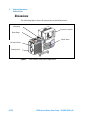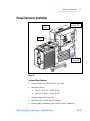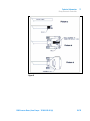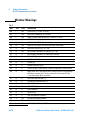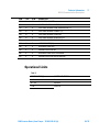
1
DS42 Inverter Rotary Vane Pumps Model: X3700-60000 Notice de Mode D’Emploi User Manual 87-900-140-01 (A) 11/2013 Notices © Agilent Technologies, Inc. 2012 No part of this manual may be reproduced in any form or by any means (including electronic storage and retrieval or translation into a foreign language) without prior agreement and written consent from Agilent Technologies, Inc. as governed by United States and international copyright laws. Manual Part Number Publication Number: 87-900-140-01 (A) Edition Edition 11/2013 Printed in ITALY Agilent Technologies Italia S.p.A. Vacuum Products Division Via F.lli Varian, 54 10040 Leinì (TO) ITALY Warranty The material contained in this document is provided “as is,” and is subject to being changed, without notice, in future editions. Further, to the maximum extent permitted by applicable law, Agilent disclaims all warranties, either express or implied, with regard to this manual and any information contained herein, including but not limited to the implied warranties of merchantability and fitness for a particular purpose. Agilent shall not be liable for errors or for incidental or consequential damages in connection with the furnishing, use, or performance of this document or of any information contained herein. Should Agilent and the user have a separate written agreement with warranty terms covering the material in this document that conflict with these terms, the warranty terms in the separate agreement shall control. Technology Licenses The hardware and/or software described in this document are furnished under a license and may be used or copied only in accordance with the terms of such license. Restricted Rights Legend If software is for use in the performance of a U.S. Government prime contract or subcontract, Software is delivered and licensed as “Commercial computer software” as defined in DFAR 252.227-7014 (June 1995), or as a “commercial item” as defined in FAR 2.101(a) or as “Restricted computer software” as defined in FAR 52.227-19 (June 1987) or any equivalent agency regulation or contract clause. Use, duplication or disclosure of Software is subject to Agilent Technologies’ standard commercial license terms, and nonDOD Departments and Agencies of the U.S. Government will receive no greater than Restricted Rights as defined in FAR 52.227-19(c)(1-2) (June 1987). U.S. Government users will receive no greater than Limited Rights as defined in FAR 52.227-14 (June 1987) or DFAR 252.227-7015 (b)(2) (November 1995), as applicable in any technical data. Trademarks Windows and MS Windows are U.S. registered trademarks of Microsoft Corporation. Safety Notices CAUTION A CAUTION notice denotes a hazard. It calls attention to an operating procedure, practice, or the like that, if not correctly performed or adhered to, could result in damage to the product or loss of important data. Do not proceed beyond a CAUTION notice until the indicated conditions are fully understood and met. WARNING A WARNING notice denotes a hazard. It calls attention to an operating procedure, practice, or the like that, if not correctly performed or adhered to, could result in personal injury or death. Do not proceed beyond a WARNING notice until the indicated conditions are fully understood and met. DS42 Inverter Rotary Vane Pumps / 87-900-140-01 (A) DS42 Inverter Rotary Vane Pumps DS42 Inverter Rotary Vane Pumps DS42 Inverter Rotary Vane Pumps / 87-900-140-01 (A) 3/78 DS42 Inverter Rotary Vane Pumps 4/78 DS42 Inverter Rotary Vane Pumps / 87-900-140-01 (A) Contents Contents Mode d’emploi 7 Indications générales 8 Emmagasinage 11 Preparation pour l‘installation 12 Installation 14 Utilisation 17 Maintenance 18 Mise au rebut 20 Instructions for Use 21 General Information 22 Storage 25 Preparation for Installation 26 Installation 28 Use 30 Maintenance Disposal 31 33 Technical Information Section I 35 37 Technical Description 37 DS42 Inverter Rotary Vane Pumps / 87-900-140-01 (A) 5/78 Contents Vacuum Seals 39 Anti-Suckback Device 40 Technical Data 41 Safety Precautions 44 Transport and Installation Section II 45 48 Connection to the Electric Supply 48 Connections to the Inlet and Exhaust Flanges 48 Starting and Running the Pump 50 Stopping the Pump 51 Safety Rules52 Warning Notes 53 Caution Notes 55 Maintenance Actions 56 Lubricants 58 Pump Electronic Controller 59 RS 232 Communication Description 64 Accessories 71 6/78 DS42 Inverter Rotary Vane Pumps / 87-900-140-01 (A) DS42 Inverter Rotary Vane Pumps Mode d’emploi Indications générales 8 Symboles utilisés 10 Emmagasinage 11 Preparation pour l‘installation Installation 14 Utilisation 17 Maintenance 18 Mise au rebut 20 12 Traduction de la mode d’emploi originale 7/78 1 Mode d’emploi Indications générales Indications générales Cet appareil a été conçu en vue d'une utilisation professionnelle. Il est conseillé à l'utilisateur de lire attentivement cette notice ainsi que toute autre information fournie par Agilent avant de l'utiliser. Agilent décline toute responsabilité en cas de non-respect total ou partiel des instructions fournies, d'utilisation in-correcte de la part du personnel non formé, d'opérations non autorisées ou d'un emploi contraire aux réglementations nationales spécifiques. Les DS42 Inverter Rotary Vane Pumps sont des pompes rotatives à deux étages étages, à palettes, étanches en bain d'huile, actionnées par un moteur électrique triphasé. Ces pompes à haut vide sont adaptées au pompage de gaz non corrosifs. Les paragraphes suivants fournissent toute l‘information nécessaire pour garantir la sécurité de l'opérateur pendant l'utilisation de l'appareil. Des ren-seignements plus détaillés se trouvent dans l'appendice «Technical Information». 8/78 DS42 Inverter Rotary Vane Pumps / 87-900-140-01 (A) 1 Mode d’emploi Indications générales Cette notice utilise les signes conventionnels suivants: AVERTISSEMENT! Les messages d’avertissement attirent l'attention de l'opérateur sur une procédure ou une manœuvre spéciale dont la mauvaise exécution risque de provoquer de graves lésions. ATTENTION! NOTE Les messages d'attention apparaissent avant certaines procédures dont le nonrespect pourrait endommager sérieusement l'appareil. Les notes contiennent des renseignements importants, isolés du texte. DS42 Inverter Rotary Vane Pumps / 87-900-140-01 (A) 9/78 1 Mode d’emploi Indications générales Symboles utilisés Les symboles suivants sont utilisés dans toutes les illustrations: Vanne de ballast à gaz Bride d’aspiration Remplissage fluide de travail Bride de vidange 10/78 DS42 Inverter Rotary Vane Pumps / 87-900-140-01 (A) Mode d’emploi Emmagasinage 1 Emmagasinage Pendant le transport et l'emmagasinage des pompes, veiller à respecter les conditions environnementales suivantes: température: de -20 °C à +70 °C humidité relative: 0 – 95 % (sans condensation) DS42 Inverter Rotary Vane Pumps / 87-900-140-01 (A) 11/78 1 Mode d’emploi Preparation pour l‘installation Preparation pour l‘installation La pompe est fournie dans un emballage de protection spécial; si l'on constate des marques de dommages pouvant s'être produites pendant le transport, contacter aussitôt le bureau de vente local. Le poids total de l'emballage avec la pompe est d’environ 13 kg maximum. Pendant l'opération d'ouverture de l'emballage, veiller tout particulièrement à ne pas laisser tomber la pompe et à ne lui faire subir aucun choc ni aucune vibration. Ne pas jeter l'emballage dans la nature. Le matériel est entièrement recyclable et il est conforme à la directive CEE 85/399 en matière de protection de l'environnement. NOTE La pompe ne peut être endommagée en restant simplement exposée à l'atmosphère. Il est de toute façon conseillé de la garder dans son emballage jusqu'au moment de sa mise en place sur le système afin d'éviter toute pollution due à la poussière. NOTE La pompe est équipée de certains accessoires standard: 1 cable de Entrée/Sortie (I/O) Ressort de maintien pour prise IEC320 1 cable d’extension IEC320 12/78 DS42 Inverter Rotary Vane Pumps / 87-900-140-01 (A) Mode d’emploi Preparation pour l‘installation DS42 Inverter Rotary Vane Pumps / 87-900-140-01 (A) 1 13/78 1 Mode d’emploi Installation Installation Ne pas installer et/ou utiliser la pompe dans des milieux exposés aux agents atmosphériques (pluie, gel, neige), à des poussières, à des gaz agressifs ainsi que dans des milieux explosifs ou à risque élevé d'incendie. Pendant le fonctionnement, il est nécessaire de respecter les conditions environnementales suivantes: Température: de +12 °C à +40 °C Humidité relative: 0 – 95 % (sans condensation) AVERTISSEMENT! Pour protéger contre les court-circuits ou les surintensités, il faut installer un disjoncteur automatique sur la ligne d’alimentation principale vers les dispositifs Agilent, de 10A de capacité. ATTENTION! Garantissez la présence d’un espace libre de 20 cm minimum autour de la pompe pour permettre une libre circulation de l’air. ATTENTION! Avant toute utilisation de la pompe, vérifier le niveau de l’huile. 14/78 DS42 Inverter Rotary Vane Pumps / 87-900-140-01 (A) 1 Mode d’emploi Installation AVERTISSEMENT! Avant toute autre opération, retirer les bouchons de protection placés sur les brides d'aspiration et de vidange. En cas de mise en marche inopinée de l'appareil, l'air contenu à l'intérieur de la pompe peut les projeter contre l'opérateur et le blesser. AVERTISSEMENT! Pendant l'installation, faire très attention à ce que la bride d'aspiration soit reliée à la chambre à vider et que la bride de vidange ne soit pas bouchée (voir la figure ci-après). La pompe ne doit pas être utilisée comme un compresseur. La pression maximale à l'intérieur du réservoir d'huile ne doit pas dépasser 1,5 bar (abs). Le non-respect de ces précautions peut entraîner un danger pour l'opérateur et endommager la machine. Bride d'aspiration Bride de vidange DS42 Inverter Rotary Vane Pumps / 87-900-140-01 (A) 15/78 1 Mode d’emploi Installation ATTENTION! Contrôler que la tension d'alimentation correspond à la gamme de tensions indiquées sur la plaquette du contrôleur. Brancher la pompe à la source d'alimentation. 16/78 DS42 Inverter Rotary Vane Pumps / 87-900-140-01 (A) 1 Mode d’emploi Utilisation Utilisation La mise en marche de la pompe ne requiert aucune manœuvre particulière; il suffit de la brancher à l'alimentation électrique et d’actionner l'interrupteur bipolaire. AVERTISSEMENT! La pompe a été conçue pour fonctionner avec des fluides neutres ou non corrosifs. L'emploi de substances potentiellement explosives ou inflammables est strictement interdit. DS42 Inverter Rotary Vane Pumps / 87-900-140-01 (A) 17/78 1 Mode d’emploi Maintenance Maintenance Le personnel chargé de la conduite et de la maintenance de la pompe doit avoir la formation nécessaire et posséder une connaissance approfondie des normes de prévention des accidents du travail. AVERTISSEMENT! Les hautes tensions peuvent entraîner la mort par contact. Veiller à toujours opérer avec le maximum de prudence et dans le respect des normes de prévention des accidents du travail en vigueur. AVERTISSEMENT! Lorsque la machine est sous tension, faire attention à la présence d'organes en mouvement et de haute tension. AVERTISSEMENT! En cas de nécessité de procéder à des opérations de maintenance de la pompe au terme d'une période de fonctionnement, il est indispensable de la laisser refroidir car sa température extérieure peut être supérieure à 60 °C. AVERTISSEMENT! Avant toute opération de maintenance, il est impératif de toujours couper l'alimentation de la pompe. Placer les panneaux spécifiques d'avertissement: APPAREIL EN COURS DE MAINTENANCE – NE PAS BRANCHER L'ALIMENTATION, près de l'interrupteur d'alimentation. Au terme des opérations de maintenance, restaurer les dispositifs de sécurité. 18/78 DS42 Inverter Rotary Vane Pumps / 87-900-140-01 (A) 1 Mode d’emploi Maintenance AVERTISSEMENT! Ne pas effectuer la substitution d'huile immédiatement après l'arrêt de la machine car la température de celle-là peut être élevée. NOTE Avant de retourner une pompe au constructeur pour réparation, il est indispensable de remplir et d'adresser au bureau local de vente la fiche “Health and Safety Certification” jointe à la présente notice. Une copie de celle-ci devra être mise dans l'emballage de la pompe avant expédition. En cas de mise au rebut de la pompe, procéder à son élimination conformément aux réglementations nationales en la matière. DS42 Inverter Rotary Vane Pumps / 87-900-140-01 (A) 19/78 1 Mode d’emploi Mise au rebut Mise au rebut Signification du logo "WEEE" figurant sur les étiquettes. Le symbole ci-dessous est appliqué conformément à la directive CE nommée "WEEE". Ce symbole (uniquement valide pour les pays de la Communauté européenne) indique que le produit sur lequel il est appliqué NE doit PAS être mis au rebut avec les ordures ménagères ou les déchets industriels ordinaires, mais passer par un système de collecte sélective. Après avoir vérifié les termes et conditions du contrat de vente, l’utilisateur final est donc prié de contacter le fournisseur du dispositif, maison mère ou revendeur, pour mettre en œuvre le processus de collecte et mise au rebut. 20/78 DS42 Inverter Rotary Vane Pumps / 87-900-140-01 (A) DS42 Inverter Rotary Vane Pumps Instructions for Use General Information 22 Symbols used 24 Storage 25 Preparation for Installation 26 Installation 28 Use 30 Maintenance 31 Disposal 33 Original Instructions 21/78 2 Instructions for Use General Information General Information This equipment is destined for use by professionals. The user should read this instruction manual and any other additional information supplied by Agilent before operating the equipment. Agilent will not be held responsible for any events occurring due to non-compliance, even partial, with these instructions, improper use by untrained persons, non-authorized interference with the equipment or any action contrary to that provided for by specific national standards. The DS42 Inverter Rotary Vane Pumps are double-stage, rotary vane pumps oil sealed, driven by a three-phase electric motor. These high vacuum pumps are suitable for pumping non corrosive gases. The following paragraphs contain all the information necessary to guarantee the safety of the operator when using the equipment. Detailed information is supplied in the appendix "Technical Information". 22/78 DS42 Inverter Rotary Vane Pumps / 87-900-140-01 (A) 2 Instructions for Use General Information This manual uses the following standard protocol: WARNING! The warning messages are for attracting the attention of the operator to a particular procedure or practice which, if not followed correctly, could lead to serious injury. CAUTION! The caution messages are displayed before procedures which, if not followed, could cause damage to the equipment. NOTE The notes contain important information taken from the text. DS42 Inverter Rotary Vane Pumps / 87-900-140-01 (A) 23/78 2 Instructions for Use General Information Symbols used The following symbols are used consistently throughout in all illustration: Gas Ballast valve Suction Flange Filling up operating fluid Exhaust Flange 24/78 DS42 Inverter Rotary Vane Pumps / 87-900-140-01 (A) Instructions for Use Storage 2 Storage When transporting and storing the pumps, the following environmental requirements should not be exceeded: temperature: from -20° to +70 °C relative humidity: 0 – 95 % (non-condensing) DS42 Inverter Rotary Vane Pumps / 87-900-140-01 (A) 25/78 2 Instructions for Use Preparation for Installation Preparation for Installation The pump is supplied in a special protective packing. If this shows signs of damage which may have occurred during transport, contact your local sales office. Total weight of the pack, including the pump, is approx. 13 Kg. When unpacking the pump, be sure not to drop it and avoid any kind of sudden impact or shock vibration to it. Do not dispose of the packing materials in an unauthorized manner. The material is 100 % recyclable and complies with EEC Directive 85/399. NOTE Normal exposure to the environment cannot damage the pump. Nevertheless, it is advisable to keep it closed until it is installed in the system, thus preventing any form of pollution by dust. NOTE The pump is provided with some standard accessories: 1 I/O cable IEC320 retention spring 1 extension cable IEC320 26/78 DS42 Inverter Rotary Vane Pumps / 87-900-140-01 (A) Instructions for Use Preparation for Installation 2 Figure 1 DS42 Inverter Rotary Vane Pumps / 87-900-140-01 (A) 27/78 2 Instructions for Use Installation Installation Do not install or use the pump in an environment exposed to atmospheric agents (rain, snow, ice), dust, aggressive gases, or in explosive environments or those with a high fire risk. During operation, the following environmental conditions must be respected: temperature: from +12 °C to +40 °C relative humidity: 0 – 95 % (non-condensing). WARNING! Protect against short circuits and overload by installing on Agilent Device electrical main line an automatic circuit breaker of 10A capacity. CAUTION! Assure a free space all around the pump at minimum of 20cm to allow proper air circulation. CAUTION! Before starting the pump, check the oil level. WARNING! Take out the protective caps on the suction and exhaust flanges before doing anything else. In the event of an accidental start-up, the air inside the pump could violently expel the protective caps and harm the operator. 28/78 DS42 Inverter Rotary Vane Pumps / 87-900-140-01 (A) Instructions for Use Installation WARNING! 2 During installation, pay maximum attention that the suction flange is connected to the vacuum chamber and the exhaust flange is not closed (see the following figure). The pump must not be used as a compressor. Maximum pressure inside the oil container must not exceed 1.5 bar (abs.). Nonobservance of these precautions may be dangerous for the machine and the operator. Inlet Flange Outlet Flange Figure 2 CAUTION! Check that your electrical mains voltage corresponds to the range indicated on controller label. Connect the pump to the power supply. DS42 Inverter Rotary Vane Pumps / 87-900-140-01 (A) 29/78 2 Instructions for Use Use Use There are no special procedures for switching the pump on; it needs only to be connected to the electric power by means of the bipolar switch. WARNING! 30/78 The pump is designed for operation with neutral or non-corrosive fluids. It is absolutely forbidden to use potentially explosive or flammable substances. DS42 Inverter Rotary Vane Pumps / 87-900-140-01 (A) 2 Instructions for Use Maintenance Maintenance Personnel responsible for pump operation and maintenance must be well-trained and must be aware of the accident prevention rules. WARNING! Death may result from contact with high voltages. Always take extreme care and observe the accident prevention regulations in force. WARNING! When machine is powered take care on account of moving parts and high voltages. WARNING! If you have to perform maintenance on the pump after a considerable time in operation, leave it to cool as temperature of the outer surface may be in excess of 60 °C. DS42 Inverter Rotary Vane Pumps / 87-900-140-01 (A) 31/78 2 Instructions for Use Maintenance WARNING! Always disconnect the power supply to the pump before starting maintenance work. Place a special warning signs over the power supply breaker switch: MACHINE UNDERGOING MAINTENANCE - DO NOT POWER ON. When finished, remove the safety warning. WARNING! Do not change the oil immediately after stopping the machine as the oil temperature may still be high. NOTE Before returning the pump to the constructor for repairs the "Health and Safety Certification" sheet attached to this instruction manual must be filled-in and sent to the local sales office. A copy of the sheet must be inserted in the pump package before shipping. If a pump is to be scrapped, it must be disposed of in accordance with the specific national standards. 32/78 DS42 Inverter Rotary Vane Pumps / 87-900-140-01 (A) Instructions for Use Disposal 2 Disposal Meaning of the "WEEE" logo found in labels The following symbol is applied in accordance with the EC WEEE (Waste Electrical and Electronic Equipment) Directive. This symbol (valid only in countries of the European Community) indicates that the product it applies to must NOT be disposed of together with ordinary domestic or industrial waste but must be sent to a differentiated waste collection system. The end user is therefore invited to contact the supplier of the device, whether the Parent Company or a retailer, to initiate the collection and disposal process after checking the contractual terms and conditions of sale. DS42 Inverter Rotary Vane Pumps / 87-900-140-01 (A) 33/78 2 Instructions for Use Disposal 34/78 DS42 Inverter Rotary Vane Pumps / 87-900-140-01 (A) DS42 Inverter Rotary Vane Pumps Technical Information Section I 37 Technical Description 37 Vacuum Seals 39 Anti-Suckback Device 40 Technical Data 41 Dimensions Safety Precautions 42 44 Transport and Installation 45 Preliminary Operations 46 Section II 48 Connection to the Electric Supply 48 Connections to the Inlet and Exhaust Flanges Starting and Running the Pump Stopping the Pump 51 Safety Rules 52 Warning Notes 53 Caution Notes 55 48 50 Maintenance Actions 56 Pump Electronic Controller 59 Technical Specifications 59 Input/Output Communications 61 P1 – I/O: Analog signals + RS232 in one port 61 Procedure to connect the I/O port to an external cable 62 Original Instructions 35/78 3 Technical Information Disposal RS 232 Communication Description 64 Communication Format 64 Communication Protocol 64 Examples 66 Window Meanings 68 Operational Limits 69 Status LED 70 Electronic Self-Test 70 Rotor Lock Test Accessories 36/78 70 71 DS42 Inverter Rotary Vane Pumps / 87-900-140-01 (A) 3 Technical Information Section I Section I Technical Description The DS42 Inverter Rotary Vane Pumps are rotary vane pumps oil sealed, driven by a three-phase electric motor. Figure 3 These vacuum pumps are suitable for pumping non corrosive gases. The main features are: all parts in direct contact with the fluid pumped are free of copper alloys; all materials are carefully selected to provide extended life; DS42 Inverter Rotary Vane Pumps / 87-900-140-01 (A) 37/78 3 Technical Information Technical Description due to its design features and low number of gaskets, the pump requires little maintenance, disassembly and reassemble are easy and require minimal time. The oil guarantees perfect sealing of the discharge valves, enters the pump to ensure lubrication and sealing of the parts inside, facilitates heat dissipation and reduces pump noise. The pump is equipped with a special anti-suckback device which automatically isolates the vacuum system when the pump stops. This avoids rises in pressure or oil flow in the vacuum system while air is allowed back into the stator chambers. The air entering the pump after the anti-suckback device has closed prevents the oil in the casing from filling the stator chambers. 38/78 DS42 Inverter Rotary Vane Pumps / 87-900-140-01 (A) 3 Technical Information Vacuum Seals Vacuum Seals A special feature of this pump is the low number of gaskets that are employed. The seals in the circuit are obtained by means of VITON gaskets. Sealing of the rotor shaft is guaranteed by a rotating gasket with dust-guard lip. The suction flange and duct are sealed by mean of OR gaskets. DS42 Inverter Rotary Vane Pumps / 87-900-140-01 (A) 39/78 3 Technical Information Anti-Suckback Device Anti-Suckback Device The pump is equipped with a special anti-suckback device to avoid air pressure rises and/or oil back-flow towards the evacuated vessel when the pump is switched off. The device includes some special features, namely: 40/78 drive obtained avoiding any form of contamination of the inlet duct by fluids (oil and/or air). Thanks to this, when the pump is started again, the pumpdown to vacuum conditions is extremely fast as these contaminants are not present and no degassing is therefore required. DS42 Inverter Rotary Vane Pumps / 87-900-140-01 (A) 3 Technical Information Technical Data Technical Data Th The following table lists the main technical data of the DS42 Inverter Rotary Vane Pumps. Tab. 1 TECHNICAL DATA Hz Units Value FREE AIR DISPLACEMENT 50 l/min (m3/h) 38 (2.3) PUMPING SPEED 50 m3/h 1.8 ULTIMATE PARTIAL PRESSURE * mbar 10-4 Range ULTIMATE TOTALE PRESSURE * mbar 4x10⁻³ ULTIMATE TOTALE PRESSURE WITH GAS BALLAST* mbar 2x10⁻² WATER VAPOR TOLERANCE mbar 15 WATER VAPOR CAPACITY g/h 60 OIL CAPACITY min/max l 0.6 OIL TEMPERATURE °C 60 (pump operating) ** °F 140 Installation category II Pollution degree 2 OPERATING TEMPERATURE RANGE °C 12 – 40 WEIGHT Kg 13 lb 28 INLET FLANGE DN 16 EXHAUST FLANGE DN 16 V 100-240 +/-10% Internal use Only Max Altitude 2000m Input Voltage 50-60 * According to PNEUROP 6602 ** At ultimate total pressure, 20 °C (68 °F) room temperature DS42 Inverter Rotary Vane Pumps / 87-900-140-01 (A) 41/78 3 Technical Information Technical Data Dimensions The following figure shows the pumps layout and dimensions: Inlet flange Electronic controller Outlet flange Electric motor Oil level indicator Pumping block Figure 4 42/78 DS42 Inverter Rotary Vane Pumps layout DS42 Inverter Rotary Vane Pumps / 87-900-140-01 (A) Technical Information Technical Data Figure 5 3 DS42 Inverter Rotary Vane Pumps dimensions DS42 Inverter Rotary Vane Pumps / 87-900-140-01 (A) 43/78 3 Technical Information Safety Precautions Safety Precautions WARNING! 44/78 Always carry the pump by means of the ring-bolt provided. The pump must be set in position taking the upmost care in order to avoid accidental falls. In case of a need to handle the pump after a period of operation, it must be left to cool first as the external surface temperature may be in excess of 60 °C. DS42 Inverter Rotary Vane Pumps / 87-900-140-01 (A) 3 Technical Information Transport and Installation Transport and Installation The pumps are shipped to the customer inside cardboard boxes. Total weight of the pack, including the pump, is about 17 Kg. The case must be handled with care, using appropriate lifting equipment. CAUTION! When moving the case, ensure that it is securely bound to the lifting equipment and that the equipment is strong enough to support the weight. The pump’s working environment is a traditional industrial environment. Naturally sites with corrosive vapors or excessive heat are best avoided. Room temperature should ideally be between 12 °C and 40 °C. If the temperature is not inside this range, consult Agilent technical service for the changes required. DS42 Inverter Rotary Vane Pumps / 87-900-140-01 (A) 45/78 3 Technical Information Transport and Installation Setting the pump in position should be performed as follows: Pump laid on the ground. There are no special instructions for this type of installation, except that the floor should be as flat as possible and suited to bear the weight of the pump (it should ideally be a concrete floor) and of any accessories mounted on it. Note that the pump is stable on its base plate and it should not be necessary to anchor it to the floor with bolts and screws; also vibrations to and from the pump are greatly reduced by the use of rubber feet. Pump off the ground. In this case, the user must design a suitable support structure, remembering the following points: the plane supporting the pump must be perfectly horizontal; the structure should be adequately rigid; the relevant safety precautions should be applied. Note also that the pump should be attached to the supporting structure after replacing the rubber feet with special anti-vibration feet, which should be screwed to the pump base and to the supporting plane. After taking the pump out of its packing case, you are advised to make the following checks: a Ensure that the pump has not suffered any damage during shipping. b Check that there are no uncovered or loose parts. Preliminary Operations Before starting the pump, check for oil level. CAUTION! 46/78 Oil must be poured into the casing through the special threaded plughole and NOT through the suction line. DS42 Inverter Rotary Vane Pumps / 87-900-140-01 (A) Technical Information Transport and Installation WARNING! 3 Take out the protective caps on the suction and exhaust flanges before doing anything else. In the event of an accidental start-up, the air inside the pump could violently expel the protective caps and harm the operator. DS42 Inverter Rotary Vane Pumps / 87-900-140-01 (A) 47/78 3 Technical Information Section II Section II Connection to the Electric Supply CAUTION! It is recommended to connect the pump to the power supply through a dedicated safety switch on the main electrical panel of the installation, or in proximity of the power supply connection point. WARNING! The pump must be installed in a way that allows an easy interruption of the line voltage. Power supply cord: The correct cable for electrical wiring is a three wires (Ph+N+Earth) cable. The wire section has to be at least 0.75 mm2 (AWG18). Connections to the Inlet and Exhaust Flanges Remove the protective caps from both flanges. Connect the system to be evacuated to the inlet flange, using a centering ring with OR and a locking collar. NOTE For guaranteed reliable sealing, use an OR gasket in Perbunan or Viton. The inlet duct is equipped with a sieve filter preventing solid particles from entering and damaging the pump. NOTE 48/78 When the gases to be pumped out contain dust, it is advisable to insert a dust filter before the inlet flange. DS42 Inverter Rotary Vane Pumps / 87-900-140-01 (A) 3 Technical Information Connections to the Inlet and Exhaust Flanges NOTE When the gases to be pumped out contain large quantities of vapor, it is advisable to include a condense separator before the inlet flange. To make best use of the pump’s capacity, use only short, straight piping, with a diameter not smaller than that of the inlet flange. NOTE If rigid piping is used, it is good practice to use a flexible joint in order to avoid undue forcing of the connection on the pump. The exhaust duct must be connected to a pipe that will take away the pumped out gases. NOTE An internal oil mist eliminator avoids pollution of the surrounding atmosphere by the oil present in the exhaust duct during pump operation. CAUTION! Never block the pump exhaust line. This would cause overpressure in the casing with the risk of breaking the oil tank. DS42 Inverter Rotary Vane Pumps / 87-900-140-01 (A) 49/78 3 Technical Information Starting and Running the Pump Starting and Running the Pump WARNING! NOTE The pump is designed for operation with neutral or non-corrosive fluids. It is absolutely forbidden to use potentially explosive or flammable substances. If the pump is started with cold oil, initially more than normal noise will be heard; this will last for a few minutes only until the oil reaches its working temperature. There are no special instructions for normal operation of the pump, which is delivered to you after completion of a runningin cycle in the factory. NOTE To allow the pump starting you have to wire properly the interlock pins by connecting the mating connector provided with the pump. NOTE For repetitive work cycles, with brief time intervals in between, it is better not to stop the pump. 50/78 DS42 Inverter Rotary Vane Pumps / 87-900-140-01 (A) Technical Information Stopping the Pump 3 Stopping the Pump There are no special procedures for switching the pump off; it needs only to be disconnected from the electric power by means of the bipolar switch. When the pump is stopped, the anti-suckback device makes it possible to maintain vacuum in the vessel connected on the inlet flange of the pump. DS42 Inverter Rotary Vane Pumps / 87-900-140-01 (A) 51/78 3 Technical Information Safety Rules Safety Rules Personnel responsible for pump operation and maintenance must be well-trained and must be aware of the accident prevention rules. The accident prevention precautions contained in this section must be respected at all times during operation and maintenance of the pump to avoid damage to operators and to the pump. These precautions are provided in the form of WARNING and CAUTION notes. WARNING! Operating procedures, technical information and precautions which, if not respected and/or implemented correctly may cause body harm to operators. NOTE Before connecting the IEC320 mains cable, install the Retention Spring provided with the MS40+. The Retention Spring has to be fastened to IEC320 connector lateral screws. NOTE Use the Retention Spring to secure the mains cable into the IEC320 socket. CAUTION! Operating procedures, technical information and precautions, which, if not respected and/or implemented correctly, may cause damage to the pump. 52/78 DS42 Inverter Rotary Vane Pumps / 87-900-140-01 (A) 3 Technical Information Warning Notes Warning Notes a Death may result from contact with high voltages. Always take extreme care and observe the accident prevention regulations in force. b Always disconnect the power supply to the pump before maintenance work. Place a special warning signs over the power supply breaker switch: MACHINE UNDERGOING MAINTENANCE - DO NOT POWER ON. c If you are performing maintenance after the pump has been operating for a considerable time, allow sufficient time for it to cool as the external surface temperature may be in excess of 60 °C. d Failure to provide the pump with an earth connection may cause serious damage to operators. Always ensure that there is an earth connection and that it complies with the standards. e When cleaning the pump and its component parts, avoid the use of flammable or toxic solvents, such as benzin, benzol, ether or alcohol. The recommendation is to use a soap and water solution, preferably in ultrasound washing machines, taking care to dry all the cleaned parts at temperatures under 100 °C in order to eliminate residual moisture. f Prolonged overloads or breakdowns may cause the electric motor to overheat,and to release noxious smoke; remove the power immediately as a precaution and do not approach the pump at least until you have provided ventilation to drive out the smoke. Take care not to breathe in the fumes remaining inside the pump in the course of repair work. g In case of fire, do not throw water on the pump. Switch the power off and use CO 2 extinguishers. h Carefully inspect the flanges to ensure that there is no dust, oil, dirt or defects of the mating surfaces, before making the required connections. i Ensure that all joints and couplings are locked correctly before starting the pump again after repair work. DS42 Inverter Rotary Vane Pumps / 87-900-140-01 (A) 53/78 3 Technical Information Warning Notes j Do not wear any objects that may become entangled in the mechanisms and/or act as conductors (chains, bracelets, etc.). k Ensure that the tools to be used are in perfect working condition and have insulating grips, where necessary. Check that the insulating material of the cables and that the conductors of the test equipment do not show any signs of damage. l Do not replace the oil immediately after stopping the machine as the oil may still be at high temperature. m Perform repairs in clean and, where possible, dustfree areas. Protect all the clearances of connection points with suitable plastic caps and cover the machined surface areas of all parts stripped down until they are put back on the pump again. 54/78 DS42 Inverter Rotary Vane Pumps / 87-900-140-01 (A) 3 Technical Information Caution Notes Caution Notes a Before putting the pump back into operation after a breakdown, inspect it and check carefully for any other signs of damage. b Use only tools that are in perfect working order and specially designed for the job; use of inappropriate or ineffective tools may cause serious damage. c Perform repairs in clean and, where possible, dust-free areas. Protect all the clearances of connection points with suitable plastic caps and cover the machined surface areas of all parts stripped down until they are put back on the pump again. d Always check the lubricant and that it is properly distributed through the pump; inadequate lubrication may damage the pump seriously. e Give the parts some form of marking as you strip them down to ensure that you reassemble them again in the proper order. f Check that there are no scratches or grooves on the machined shafts, in their seats inside the pump or on machine-ground surfaces. Slight scratches and abrasions may be eliminated with very fine emery paper or by a little light grinding. g Before putting a group together, always spread a little oil over inner parts and mating surfaces. Replace all seals with original spare parts before reassembling components. DS42 Inverter Rotary Vane Pumps / 87-900-140-01 (A) 55/78 3 Technical Information Maintenance Actions Maintenance Actions Maintenance may be seen as the totality of all scheduled and unscheduled maintenance work. SCHEDULED MAINTENANCE: Maintaining the nominal state of operation. Tab. 2 Oil level checking Daily (before every starting) Oil change 8.000 hours (light applications) Exhaust filter replacement If oil mist at exhaust or yearly Fan cover cleaning 6 months NOTE UNSCHEDULED MAINTENANCE: Restoring the nominal state of operation. The frequency with which repairs are performed depends on the process and presence of substances that shorten pump life (dust, abrasives, solvents, water, chemically aggressive substances). The pump must be cleaned at regular intervals of time. CAUTION! Do not clean with Alcohol the plastic or rubber components of the pump. Use only the strictly necessary amount of lubricant; an excess of lubricating oil, like when there is none, may sometimes compromise proper operation of the pump. Only the recommended lubricants, or lubricating oils with similar characteristics and known and experimented quality, should be used. Oil changes must be made with the oil at a sufficiently high temperature, after leaving the pump to cool for a few minutes following operation. The drain and filler plugs must not be left open any longer than is strictly necessary. When performing maintenance, look out for all signals that may precede a breakdown, in particular: 56/78 traces of corrosion; DS42 Inverter Rotary Vane Pumps / 87-900-140-01 (A) 3 Technical Information Maintenance Actions oil leaks; slack joints or couplings. Maintenance technicians must: be aware of all applicable national directives concerning accident prevention during work on motor-driven pumps and should know how to apply them; have read and understood all the sections on “Safety Rules"; be familiar with the essential design features and operation of the pump; know how to use and consult the pump documentation; be concerned about proper operation of the pump; make a note of any irregularities in operation of the pump and take the necessary action, where appropriate. Use original spare parts wherever possible and repair a broken part as best as possible on site or send it back to the manufacturer for repairs. For all problems arising, or to order spare parts, refer to our service department. Agilent Technologies Italia S.p.A. Vacuum Products Division Via F.lli Varian 54 10040 Leini, (Torino) – Italy Tel.: +39 011 997 9111 Fax: +39 011 997 9350 Toll-Free: 00 800 234 234 00 DS42 Inverter Rotary Vane Pumps / 87-900-140-01 (A) 57/78 3 Technical Information Lubricants Lubricants The recommended lubricating oil is the Agilent Rotary Vane Fluid DS45 Type. The Rotary Vane Fluid DS45 Type is a general purpose mechanical pump fluid specifically engineered to provide superior performance in high speed direct drive mechanical pumps. These precisely distilled fluids (100 % solvent refined neutral paraffinic oil) deliver lower base pressure capability, faster pumpdown cycles, and reduced maintenance requirements on both the pump and the fluid. It is absolutely necessary to continue using the lubricants initially used to fill the tank. If this is not possible for organizational or business reasons, use only products with the same characteristics as the previous oils. Only use of lubricants of suitable quality will guarantee safe operation of the pumps. CAUTION! Mineral oils and the PFPE oil are incompatible. To change from one type to another, the pump must be stripped down completely and all parts washed carefully to eliminate all oil residues. If you expect to have to use other lubricants, first find out if the two products are compatible. In cases of doubt, the lubricant used up to that time must be flushed out by way of a pump flushing procedure. CAUTION! 58/78 To avoid the risk of contaminating the oil, absolute cleanliness of the pump and surrounding area must be ensured during the lubrication procedures. DS42 Inverter Rotary Vane Pumps / 87-900-140-01 (A) 3 Technical Information Pump Electronic Controller Pump Electronic Controller I/0 port (P1) Switch Mains Status LED Figure 6 Technical Specifications Input voltage: 100V-240Vac ±10%, 50/60 Hz Max input power: 100 Vac, 3.05 Aac /305VA 221W 240 Vac, 1.34Aac / 331Va 215/W Output voltage: 240 Vrms 3ph; Max frequency: 100 Hz (factory setting) Starting phase maximum power: 200 W (max 30 minutes) DS42 Inverter Rotary Vane Pumps / 87-900-140-01 (A) 59/78 3 Technical Information Pump Electronic Controller Normal Operation maximum power: 150 W Maximum room temperature: 40 °C Protection level: IP 20 Touch current: ca. 1.1 mA (264Vac, 60 H, 150 W @ 100 Hz) Inrush current: 120Vac, 20A 240Vac, 40A CE mark: Tab. 3 EN61326-1 2006 Elctrical equipmnt for measurement control and laboratory use EMC Requirements Emission Class « A » -10dB Immunity industrial levels according to Tab. 2 EN61000-4-2 EN61000-4-8 EN61000-4-3 EN61000-4-11 EN61000-4-4 EN61000-4-12 EN61000-4-5 EN61010-1 EN61000-4-6 CSA mark: EN61010-1, 2001 (Safety requirements for electrical equipment for measurement control laboratory use) NOTE Before connecting the IEC320 mains cable, install the Retention Spring provided with the DS42 Inverter Rotary Vane Pump. The Retention Spring has to be fastened to IEC320 connector lateral screws. NOTE Use the Retention Spring to secure the mains cable into the IEC320 socket. 60/78 DS42 Inverter Rotary Vane Pumps / 87-900-140-01 (A) 3 Technical Information Pump Electronic Controller Input/Output Communications P1 – I/O: Analog signals + RS232 in one port Tab. 4 PIN N. SIGNAL NAME IN / OUT 1 Interlock. Status (N.O. relay contact) out 2 TX (RS232) 3 RX (RS232) 4 Spare 5 GND 6 Interlock. Status (N.O. relay contact) out 7 Low speed in 8 Start / Stop in 9 24V out Interlock: N.O. Relay contact – It is closed as soon as the rotational frequency exceed the threshold defined with window no.102 (plus histerisys defined by window 105). Factory set 62 Hz. Start/stop: If the inverter is managed by remote port it manages the pump starting. Connect it to +24V (pin 9) to start the pump. Low speed: If the inverter is managed by remote port it set the pump low speed. When it is left open (or tied to GND) the frequency setting is HIGH SPEED, if it is connected to +24V (pin 9) the frequency setting is LOW SPEED. The controller inputs are 0..24V active high. To activate the input related functionally it should be tied to 24Vdc (pin )), a non active state could be obtained either leaving the input not connected or connecting it to GND. When active, it sources a current less of equal to 6 mA. Active state: Vinput 12V or Isink 1.6 mA Non acctive state: Vinput ≤ 4V or Isink≤ 0.1 mA DS42 Inverter Rotary Vane Pumps / 87-900-140-01 (A) 61/78 3 Technical Information Pump Electronic Controller Here below there is a typical connection of trhe input to an external system output. Figure 7 NOTE The pump operation is I/O signals dependent so you must always plug-in the provided mating connector to start the pump. Procedure to connect the I/O port to an external cable The following picture shows the right procedure to connect a cable to the I/O port connector. A shielded cable of 30 m maximum length has to be utilized for both serial and I/O port connection. NOTE 62/78 Take care to have a good contact (soldered) between the metallic connector case and the external shield of the cable. Moreover, this connection has to be assured at least on the controller side. DS42 Inverter Rotary Vane Pumps / 87-900-140-01 (A) Technical Information Pump Electronic Controller 3 Figure 8 DS42 Inverter Rotary Vane Pumps / 87-900-140-01 (A) 63/78 3 Technical Information RS 232 Communication Description RS 232 Communication Description The RS 232 interface is available on the P1 I/O connector. Communication Format 8 data bit no parity 1 stop bit baud rate: 600/1200/2400/4800/9600/19200/38400 programmable Communication Protocol The communication protocol is a MASTER/SLAVE type where: Host = MASTER Controller = SLAVE The communication is performed in the following way: 1. the host (MASTER) send a MESSAGE + CRC to the controller (SLAVE); 2. the controller answer with an ANSWER + CRC to the host. The MESSAGE is a string with the following format: <STX>+<ADDR>+<WIN>+<COM>+<DATA>+<ETX>+<CRC> Where: NOTE 64/78 When a data is indicated between two quotes (‘...’) it means that the indicated data is the corresponding ASCII character. <STX> (Start of transmission) = 0x02 <ADDR> (Unit address) = 0x80 (for RS 232) DS42 Inverter Rotary Vane Pumps / 87-900-140-01 (A) 3 Technical Information RS 232 Communication Description <WIN> (Window) = a string of 3 numeric character indicating the window number (from ‘000’ to ‘999’); for the meaning of each window see the relevant paragraph. <COM> (Command) = 0x30 to read the window, 0x31 to write into the window <DATA> = an alphanumeric ASCII string with the data to be written into the window. In case of a reading command this field is not present. The field length is variable according to the data type as per the following table: Tab. 5 Data Type Field Length Valid Characters Logic (L) 1 ‘0’ = OFF ‘1’ = ON Numeric (N) 6 ‘-‘, ‘.’, ‘0’ . . . ‘9’ right justified with ‘0’ Alphanumeric (A) 10 from blank to ‘_’ (ASCII) <ETX> (End of transmission) = 0x03 <CRC> = XOR of all characters subsequent to <STX> and including the <ETX> terminator. The value is hexadecimal coded and indicated by two ASCII character. The addressed SLAVE will respond with an ANSWER whose structure depends from the MESSAGE type. When the MESSAGE is a reading command, the SLAVE will respond transmitting a string with the same structure of the MESSAGE. DS42 Inverter Rotary Vane Pumps / 87-900-140-01 (A) 65/78 3 Technical Information RS 232 Communication Description The controller can answers with the following response types: Tab. 6 Type Length Value Description Logic 1 byte - after a read instruction of a logic window Numeric 6 bytes - after a read instruction of a numeric window Alphanumeric 10 bytes - after a read instruction of an alphanumeric window ACK 1 byte (0x6) the command execution has been successfully completed NACK 1 byte (0x15) the command execution has been failed Unknown Window 1 byte (0x32) the specified window in the command is not a valid window Data Type Error 1 byte (0x33) the data type specified in the command (Logic, Numeric or Alphanumeric) is not accorded with the specified Window Out of Range 1 byte (0x34) the value expressed during a write command is out of the range value of the specified window Win Disabled 1 byte (0x35) the specified window is Read Only or temporarily disabled (for example you can’t write the Soft Start when the Pump is running) Examples Command: START Source: PC Destination: Pump 66/78 02 80 STX ADDR 30 30 30 WINDOW 31 31 03 WR ON ETX 42 33 CRC DS42 Inverter Rotary Vane Pumps / 87-900-140-01 (A) 3 Technical Information RS 232 Communication Description Source: Pump Destination: PC 02 80 06 03 38 35 STX ADDR ACK ETX CRC Command: STOP Source: PC Destination: Pump 02 80 30 30 STX ADDR WINDOW 30 31 30 03 42 32 WR OFF ETX CRC Source: Pump Destination: PC 02 80 06 03 38 35 STX ADDR ACK ETX CRC Command: READ PUMP STATUS Source: PC Destination: Pump (with address = 3) 02 STX 83 ADDR 32 30 35 WINDOW 30 RD 03 ETX 38 37 CRC Source: Pump (with address = 3 in stop status) Destination: PC 02 83 STX ADDR 32 30 35 WINDOW 30 30 30 30 30 DATA (STATUS) DS42 Inverter Rotary Vane Pumps / 87-900-140-01 (A) 30 03 ETX 38 37 CRC 67/78 3 Technical Information RS 232 Communication Description Window Meanings Tab. 7 WIN TYPE R/W DESCRIPTION 000 L RW START/STOP (1= START ; 0= STOP) 001 L RW LOW SPEED COMMAND (1=On; 0=Off) 008 L RW REMOTE/SERIAL CONFIGURATION (1= Remote ; 0= Serial) 102 N RW SET POINT VALUE [Hz] (0 – 124) 105 N RW SET POINT HYSTERESIS [%] (0 – 100) 108 N RW BAUD RATE (0-6) [600, 1200, 2400, 4200, 9600, 19200, 38400] 117 N RW LOW SPEED ADJUST [Hz] (62 – 100) 120 N RW ROTATIONAL FREQUENCY SETTING [Hz] (62 - 100) 127 N R ROTATIONAL FREQUENCY SETTING [rpm] (read only) 200 N R BUS CURRENT [mA] 201 N R 3PHASE VOLTAGE [Vrms] 202 N R POWER [W] 203 N R DRIVING FREQUENCY [Hz] 205 N R STATUS (0=stop; 1=wait interlock; 2=start; 3=autotuning; 5=normal; 6=fail) 206 N R ERROR CODE: Bit 7: Rotor blocked; Bit 6: shortcircuit; Bit 5: Vdc Overvoltage; Bit 4:Motor overtemp; Bit 3: Too long starting; Bit 2: Controller IGBT; Bit 1: Vdc Undervoltage; Bit 0: overcurrent 211 N R HEATSINK TEMPERATURE [°C] 216 N R CONTROLLER TEMPERATURE [°C] 234 N R BUS VOLTAGE [V] 300 N R CYCLE TIME [min] 301 N R CYCLE NUMBER 302 N R PUMP LIFE [h] 307 N R TIME CONTROLLER STAND BY 319 A RW CONTROLLER MODEL NUMBER 320 A RW PUMP MODEL NUMBER 321 A RW PUMP SPECIAL MODEL NUMBER 68/78 DS42 Inverter Rotary Vane Pumps / 87-900-140-01 (A) Technical Information RS 232 Communication Description WIN TYPE R/W DESCRIPTION 322 A RW PUMP SERIAL NUMBER 323 A RW CONTROLLER SERIAL NUMBER 362 N R LAST HOUR AVERAGE PUMP TEMPERATURE [°C] 363 N R LAST HOUR AVERAGE CURRENT [°C] 364 N R LAST HOUR AVERAGE POWER [W] 365 N R LAST HOUR AVERAGE FREQUENCY [Hz] 382 N R AVERAGE PUMP TEMPERATURE [°C] 384 N R AVERAGE POWER [W] 400 A R PROGRAM LISTING CRC 402 A R PARAMETER LISTING CRC 406 A R PROGRAM LISTING CODE & REVISION 407 A R PARAMETER LISTING CODE & REVISION 3 Operational Limits Tab. 8 INPUT VOLTAGE (V) CONTROLLER STATUS < 90 Power fail 90 – 264 Operative > 264 Power fail DS42 Inverter Rotary Vane Pumps / 87-900-140-01 (A) 69/78 3 Technical Information RS 232 Communication Description Status LED Tab. 9 NOTE LED STATUS CONTROLLER STATUS Green blinking (once every 2 seconds) Stop Green blinking Ramp – Autotuning Green Normal Operation Red Fail When you switch the controller on an electronic self-test is performed, during such phase you’ll see the led Orange for 1 sec. and turned off for two other seconds. Electronic Self-Test When you switch the pump on with the main On/Off switch the pump doesn’t start immediately but it starts only after about two seconds. This test time isn’t required if the pump is already powered as when it is operated in remote or serial mode. Rotor Lock Test The rotational frequency is checked continuously. If the rotor remains still for more than 20 sec. the pump status is changed to “Fail”. 70/78 DS42 Inverter Rotary Vane Pumps / 87-900-140-01 (A) Technical Information Accessories 3 Accessories Tab. 10 PART NUMBER DESCRIPTION 949-9305M001 MS40+ Exhaust filter G3870-60000 DS 42 3PH I/O cable DS42 Inverter Rotary Vane Pumps / 87-900-140-01 (A) 71/78 3 Technical Information Accessories 72/78 DS42 Inverter Rotary Vane Pumps / 87-900-140-01 (A) Request for Return Form United States Agilent Technologies Vacuum Products Division 121 Hartwell Avenue Lexington, MA 02421 - USA Tel.: +1 781 861 7200 Fax: +1 781 860 5437 Toll-Free: +1 800 882 7426 Sales and Service Offices India Agilent Technologies India Pvt. Ltd. Vacuum Product Division G01. Prime corporate Park, 230/231, Sahar Road, Opp. Blue Dart Centre, Andheri (East), Mumbai – 400 099.India Tel: +91 22 30648287/8200 Fax: +91 22 30648250 Toll Free: 1800 113037 Italy Agilent Technologies Italia S.p.A. Vacuum Products Division Via F.lli Varian 54 10040 Leini, (Torino) - Italy Tel.: +39 011 997 9111 Fax: +39 011 997 9350 Toll-Free: 00 800 234 234 00 Southeast Asia Agilent Technologies Sales Sdn Bhd Vacuum Products Division Unit 201, Level 2 uptown 2, 2 Jalan SS21/37, Damansara Uptown 47400 Petaling Jaya, Selangor, Malaysia Tel : +603 7712 6106 Fax: +603 6733 8121 Taiwan Agilent Technologies Taiwan Limited Vacuum Products Division (3F) 20 Kao-Shuang Rd., Pin-Chen City, 324 Taoyuan Hsien , Taiwan, R.O.C. Tel. +886 34959281 Toll Free: 0800 051 342 Canada Central coordination through: Agilent Technologies Vacuum Products Division 121 Hartwell Avenue Lexington, MA 02421 - USA Tel.: +1 781 861 7200 Fax: +1 781 860 5437 Toll-Free: +1 800 882 7426 Japan Agilent Technologies Japan, Ltd. Vacuum Products Division 8th Floor Sumitomo Shibaura Building 4-16-36 Shibaura Minato-ku Tokyo 108-0023 - Japan Tel.: +81 3 5232 1253 Fax: +81 3 5232 1710 Toll-Free: 0120 655 040 UK and Ireland Agilent Technologies UK, Ltd. Vacuum Products Division 6 Mead Road Oxford Industrial Park Yarnton, Oxford OX5 1QU – UK Tel.: +44 (0) 1865 291570 Fax: +44 (0) 1865 291571 Toll free: 00 800 234 234 00 China Agilent Technologies (China) Co. Ltd Vacuum Products Division No.3, Wang Jing Bei Lu, Chao Yang District, Beijing, 100102 China Tel.: +86 (10) 6439 7718 Toll-Free: 800 820 6556 France Agilent Technologies France Vacuum Products Division 7 Avenue des Tropiques Z.A. de Courtaboeuf - B.P. 12 91941 Les Ulis cedex - France Tel.: +33 (0) 1 69 86 38 84 Fax: +33 (0) 1 69 86 29 88 Toll free: 00 800 234 234 00 Germany and Austria Agilent Technologies Vacuum Products Division Alsfelder Strasse 6 Postfach 11 14 35 64289 Darmstadt – Germany Tel.: +49 (0) 6151 703 353 Fax: +49 (0) 6151 703 302 Toll free: 00 800 234 234 00 Korea Agilent Technologies Korea, Ltd. Vacuum Products Division Shinsa 2nd Bldg. 2F 966-5 Daechi-dong Kangnam-gu, Seoul Korea 135-280 Tel.: +82 2 3452 2452 Fax: +82 2 3452 2451 Toll-Free: 080 222 2452 Mexico Agilent Technologies Vacuum Products Division Concepcion Beistegui No 109 Col Del Valle C.P. 03100 – Mexico, D.F. Tel.: +52 5 523 9465 Fax: +52 5 523 9472 Other Countries Agilent Technologies Italia S.p.A. Vacuum Products Division Via F.lli Varian 54 10040 Leini, (Torino) Italy Tel.: +39 011 997 9111 Fax: +39 011 997 9350 Toll-Free: 00 800 234 234 00 Benelux Agilent Technologies Netherlands B.V. Vacuum Products Division Herculesweg 8 4338 PL Middelburg The Netherlands Tel.: +31 118 671570 Fax: +31 118 671569 Toll-Free: 00 800 234 234 00 Singapore Agilent Technologies Singapore Pte. Ltd, Vacuum Products Division Agilent Technologies Building, 1 Yishun Avenue 7, Singapore 768923 Tel : (65) 6215 8045 Fax : (65) 6754 0574 © Agilent Technologies, Inc. 2013 Printed in ITALY 11/2013 Publication Number: 87-900-140-01 (A) Customer Support & Service NORTH AMERICA: Toll Free: 800 882 7426, Option 3 [email protected] EUROPE: Toll Free: 00 800 234 234 00 [email protected] PACIFIC RIM: please visit our website for individual office information http://www.agilent.com Worldwide Web Site, Catalog and Order On-line: www.agilent.com Representative in most countries 12/10