1
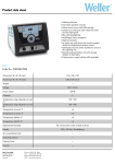
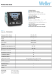
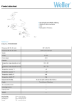
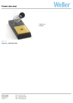
BGA / QFP-Rework System WQB 3000
Manuel d‘Utilisation
Version 1.4
2
Table des matières
1
Description
Caractéristiques techniques
2
Mise en service
2.1 Installation
2.2 Préparatifs
2.3 Fixation et positionnement de la carte imprimée et de la buse de soudage
3
Utilisation avec l'unité de programmation
3.1 La courbe de température
3.2 Démarrage du processus de soudage
3.3 Déroulement du programme
3.4 Modification des paramètres de soudage
3.5 Mémorisation et chargement de programmes
3.6 Détermination de la courbe de température avec des sondes externes (Teach-In)
Teach-In automatique
Teach-In manuel
3.7 Fonctions spéciales
4
Utilisation de la tête de soudage et de la tête de placement
5
Placement des composants
6
Description des modules
6.1 Appareil de base
6.2 Tête de soudage
6.3 Tête de placement
6.4 Chauffage inférieur
6.5 Support de carte imprimée
6.6 Unité de programmation
7
Fournitures
8
Accessoires
9
Liste des pièces de rechange
10
Tableau des buses à gaz chaud
11
Consignes de sécurité
12
Avertissements
13
Illustrations
Cooper Tools GmbH, Carl-Benz-Str. 2, 74354 Besigheim, P.O. Box 1351
Germany, Tel: (07143) 580-0, Fax: (07143) 580108
3
1
Description
Le système de réparation WQB 3000 est conçu pour effectuer des réparations de qualité aussi bien sur des
composants BGA que sur des composants FINEPITCH. Le concept sophistiqué de l'appareil allie une
grande fiabilité, une sécurité maximale du processus, une utilisation agréable et des solutions détaillées
techniquement au point. Des accessoires viennent compléter les possibilités d'emploi de ce système de
réparation.
La réparation universelle de cartes imprimées avec des composants SM nécessite un préchauffage efficace
de la carte par le bas et un chauffage contrôlé des composants à réparer par le haut pour les amener à la
température de Reflow, de même qu'un contrôle fiable du processus. Le chauffage infrarouge inférieur
régulé à 2 zones du WQB 3000 assure un chauffage rapide et une température homogène du substrat. Le
chauffage supérieur à gaz chaud à régulation numérique pour la surveillance de la température et régulation
du débit d'air autorise un dosage précis de la chaleur sur les composants. Une sonde de température placée
directement sur la buse à gaz chaud assure une régulation efficace du chauffage supérieur et autorise un
contrôle maximal du processus.
Toutes les étapes du processus peuvent être programmées, mémorisées et éventuellement verrouillées
pour en empêcher tout accès non autorisé sur l'unité de programmation numérique. Les principaux
paramètres du processus peuvent être visualisés durant l'exécution sur l'afficheur à cristaux liquides.
L'appareil de programmation permet de déterminer des courbes de température et de définir ainsi très
facilement les paramètres optimaux des processus de soudage. La programmation de nombreuses fonctions
spéciales permet d'adapter le processus aux conditions les plus variées et d'effectuer des réparations sur les
circuits les plus difficiles.
Le système de mini gabarit WELLER, éprouvé et breveté, est disponible pour le placement des composants
neufs après le dessoudage et l'application partielle de pâte à braser.
Cooper Tools GmbH, Carl-Benz-Str. 2, 74354 Besigheim, P.O. Box 1351
Germany, Tel: (07143) 580-0, Fax: (07143) 580108
4
Caractéristiques techniques :
Dimensions (L x l x h)
Tension secteur
Fusible secteur
Puissance
:
:
:
:
Alim. en air comprimé
Convertisseur d'air compr.
Réglage de température
:
:
:
Réglage du débit
Poids total
:
:
2
env. 650 X 600X 500 mm
230V, 50/60Hz
T10A
2300W
chauffage supérieur :
700 W
chauffage inférieur :
grand 1600W (260 X 260)mm
petit 400W ( 120 X 120)mm
400 – 600 kPa, air comprimé purifié, sec.
dépression de 60kPa
en continu de 50°C à 400°C
précision de réglage ± 10°C
en continu de 5 à 50 l/min.
42 kg
Mise en service
2.1 Installation
L'appareil de base (18) est équipé de 4 pieds réglables en hauteur.
La hauteur peut être réglée sans outil, en tournant les pieds à la main.
Les chariots de guidage de la tête de soudage et de la tête d'aspiration sont fixés à la position extérieure
durant le transport. Des vis de fixation pour le transport se trouvent à gauche et à droite sur le boîtier, à la
hauteur des bras. Ces vis doivent être entièrement retirées.
2.2 Préparatifs et branchements
Brancher l'unité de programmation pour WQB3000 sur la prise (15) et la fixer.
Une alimentation externe en air comprimé est nécessaire au fonctionnement de l'appareil.
La pression d'entrée est comprise entre 4 et 6 bars. Il est recommandé d'utiliser une vanne de régulation
externe pour régler la pression d'entrée. L'air comprimé doit être purifié et sec.
Le raccordement de l'air comprimé à l'appareil se fait avec un flexible de 6 mm de diamètre extérieur.
Enfoncer le flexible à fond dans l'élément de raccordement (14). Le système peut également être rééquipé
en option pour un fonctionnement du chauffage supérieur à l'azote. En plus du raccord d'air comprimé, il est
alors nécessaire de raccorder à l'élément de raccordement pour l'azote (30) un flexible de 6 mm de diamètre
extérieur.
S'assurer que l'interrupteur secteur est coupé.
Raccorder la tension secteur à l'élément de branchement secteur (16) en vérifiant les indications qui figurent
sur la plaque signalétique. Le raccordement au secteur doit être effectué uniquement avec un câble, un
connecteur ou un adaptateur agréé.
Monter la sonde pour la régulation de la température sur la buse à air chaud adaptée au composant. Pour ce
faire, visser la sonde de température dans la buse (à 45°).
Monter la buse à air chaud (8) avec la sonde de température sur la tête de soudage (13). Pour ce faire,
basculer le levier de verrouillage du raccord rapide (9) d'env. 90°, mettre la buse en place et la verrouiller.
Brancher le connecteur de la sonde de température sur la prise (1) de la tête de soudage.
Cooper Tools GmbH, Carl-Benz-Str. 2, 74354 Besigheim, P.O. Box 1351
Germany, Tel: (07143) 580-0, Fax: (07143) 580108
5
2.3 Fixation et positionnement de la carte imprimée et de la buse de soudage
La table de travail est équipée d'un support de carte imprimée x – y à réglage de précision. Les bras du
support (21) peuvent être déplacés après avoir desserré les vis de blocage (22). La carte à réparer peut
alors être mise en place. Déplacer les deux bras en direction x et la carte sur le support en direction y pour
positionner approximativement le composant à réparer par rapport à la buse. Fixer ensuite de nouveau les
deux bras avec les vis de blocage (22). Descendre la buse à air chaud (8) pour vérifier la position du
composant sur la carte imprimée par rapport à la buse et ajuster la position à l'aide de la vis de réglage en
direction X (24) et en direction Y (20).
Le chauffage inférieur peut être déplacé dans le sens de la longueur de la table de base pour un
préchauffage efficace de la carte imprimée. Pour ce faire, visser la barre (31) (fournie) soit dans la partie
gauche, soit dans la partie droite du boîtier du chauffage inférieur. Le chauffage inférieur peut maintenant
être placé de manière optimale par rapport à la carte positionnée.
Un positionnement selon l'axe thêta peut également être nécessaire suivant le placement du composant,
notamment dans le cas des composants tournés de 45°. Pour ce faire, desserrer la vis de blocage au bas de
la tête de soudage et régler avec le levier de réglage thêta (3) l'angle de la buse à air chaud (-5° à 95°).
Serrer ensuite de nouveau la vis de blocage.
La butée de profondeur de la tête de soudage doit en outre être réglée avec la vis moletée (28). Lorsque la
tête de soudage est abaissée, la buse à gaz chaud ne doit exercer aucune pression sur la carte imprimée. Si
la place autour du composant à réparer ne suffit pas compte tenu des dimensions de la buse, la buse peut
être placée à une distance définie au-dessus de la carte imprimée.
Durant le dessoudage, le composant est soulevé par un dispositif d'aspiration intégré à la buse. La vis
moletée (26) de la tête de soudage permet de régler la hauteur du tube d'aspiration (27) de manière à
adapter la position du tube à la hauteur spécifique du composant et à la distance entre la buse et la carte
imprimée.
3
Utilisation avec l'unité de programmation
Lorsque les préparatifs sont terminés, l'appareil peut être mis sous tension avec l'interrupteur secteur (16).
L'afficheur à cristaux liquides de l'unité de programmation (17) indique brièvement le nom de la société et de
l'appareil de même que la version du programme.
Au bout d'env. 4 secondes, l'affichage d'état apparaît. La LED Power de l'appareil de base est allumée.
L'appareil est opérationnel.
3.1 La courbe de température
Le soudage et le dessoudage des composants BGA ou Fine-Pitch se font d'après une courbe de
température en fonction du temps. La courbe de température comprend 4 phases.
Phase de préchauffage 1
Phase de préchauffage 2
Reflow
Phase de refroidissement
(STEP 1)
(STEP 2)
(STEP 3)
(COOLING)
Les unités de programmation contiennent d'origine des valeurs standards qui servent de grandeurs de
référence pour les programmes spécifiques des clients (voir 3.4. Modification des paramètres de soudage).
Les réglages suivants doivent être effectués sur l'unité de programmation pour définir une courbe de
température spécifique du client :
Cooper Tools GmbH, Carl-Benz-Str. 2, 74354 Besigheim, P.O. Box 1351
Germany, Tel: (07143) 580-0, Fax: (07143) 580108
6
Réglage des paramètres STEP 1 – STEP 3
Température du chauffage inférieur
Température de la buse
Débit d'air (5 – 50l/min)
Temps
50°C
50°C
10%
0sec.
-
400°C
400°C
100%
999sec.
Réglages complémentaires
Temps de refroidissement
Taille du chauffage inférieur
0sec. - 999sec.
Small / Large
Chauffage inférieur
Chauffage supérieur (buse de
soudage
Carte imprimée (sonde externe)
Step 1
Step 2 Step 3
Cooling
3.2 Démarrage du processus de soudage
L'affichage d'état apparaît sur l'afficheur de l'unité de programmation (17).
S T A T U S
P 0 1
- - - - - - - - - - - - - - - - - - - 1 0 0 ° C
→P R E H E A T T T E M P .
Affichage d'état
Etat de base de l'unité
de programmation
Les touches fléchées < > permettent de sélectionner Preheat Temp., Nozzle Temp. et les thermocouples
optionnels Sensor1 et Sensor2. Les températures momentanées sont indiquées sur l'afficheur.
Cooper Tools GmbH, Carl-Benz-Str. 2, 74354 Besigheim, P.O. Box 1351
Germany, Tel: (07143) 580-0, Fax: (07143) 580108
7
Le processus de soudage est généralement activé en pressant la touche START alors que la buse à gaz
chaud est soulevée.
S T
- →N
T I
E
O
M
P 1
- - - - - - - - - - - - - Z Z L E
T E M P
0 5
E
R E M A I N I N G
0 7
P 0 1
- - 0 ° C
0
s
Démarrage du programme
Démarrage et exécution du
programme sélectionné.
Le processus de soudage peut être arrêté à tout moment avec la touche Stop. Un nouvel actionnement de la
touche Stop permet d'activer et de désactiver le ventilateur de refroidissement.
3.3 Déroulement du programme
La courbe de température décrite en 3.2 est exécutée durant le déroulement du programme. L'étape en
cours du programme est indiquée par l'afficheur de l'unité de programmation et la LED de gauche (29) de
l'appareil de base.
STEP 1
STEP 2
STEP 3
COOLING
ère
: Déroulement 1 étape du programme, un signal sonore indique la fin de la phase de
préchauffage 1
ème
: Déroulement 2
étape du programme phase de préchauffage 2
ème
: Déroulement 3
étape du programme phase de Reflow
ème
: Déroulement 4
étape du programme, un signal sonore indique la fin de la phase de
refroidissement
Durant l'exécution de ces phases du programme, les températures momentanées des sondes raccordées
peuvent être visualisées en les sélectionnant avec les touches fléchées < >.
NOZZLE TEMP
: Température réelle du chauffage supérieur (buse de soudage)
PREHEATTEMP
: Température réelle du chauffage inférieur
SENSOR1
: Sonde externe 1 (thermocouple type K) en option
SENSOR2
: Sonde externe 2 (thermocouple type K) en option
L'afficheur de l'unité de programmation indique en outre le temps restant “ TIME REMAINING“ de l'étape en
cours du programme.
Les LED Top Heater et Bottom Heater à droite de l'appareil de base permettent de contrôler visuellement la
régulation du chauffage supérieur à gaz chaud et du chauffage inférieur à infrarouge.
Pour démarrer le processus de dessoudage, la touche DESOLD. (Desoldering) doit être enfoncée avant le
début de l'exécution du programme. La LED Desoldering de l'appareil de base s'allume et le tube
d'aspiration de la tête de soudage descend. Le dispositif d'aspiration intégré à la buse est alors
automatiquement activé à la fin du processus. L'aspiration doit ensuite être désactivée manuellement avec la
touche VAC.
Cooper Tools GmbH, Carl-Benz-Str. 2, 74354 Besigheim, P.O. Box 1351
Germany, Tel: (07143) 580-0, Fax: (07143) 580108
8
3.4 Modification des paramètres de soudage
Les paramètres peuvent être modifiés temporairement pour adapter le processus de soudage à la carte à
réparer. Cette fonction peut être exécutée uniquement lorsque l'unité de programmation n'est pas
verrouillée. L'emplacement du programme mémorisé reste inchangé.
L'unité de programmation est sur affichage d’état (quitter un éventuel menu actif avec la touche EXIT).
Appuyer sur la touche PROGRAMM pour modifier les paramètres de soudage.
S T E P 1
P 0 1
- - - - - - - - - - - - - - - - - - - 3 0 0 ° C
→P R E H E A T T E M P .
Mode programme
Modification temporaire des
paramètres du processus
Les touches fléchées < > permettent de se déplacer entre les différents paramètres du programme.
Les touches fléchées ∧ ∨ permettent de modifier les valeurs.
Les paramètres suivants peuvent être modifiés
STEP 1 – STEP 3
PREHEATTEMP
NOZZLE TEMP
AIRFLOW
TIME
Température du chauffage inférieur
Température de la buse
Débit d'air (5 – 50l/min)
Temps
50°C
50°C
10%
0sec.
-
400°C
400°C
100%
999sec.
Temps de refroidissement
Taille du chauffage inférieur
0sec. - 999sec.
Small / Large
Ainsi que
COOLING TIME
PREHEATZONE SIZE
Lorsque le menu a été quitté avec la touche EXIT, le processus de soudage peut être lancé avec les valeurs
modifiées.
En pressant une nouvelle fois la touche PROGRAMM, les valeurs modifiées sont sauvegardées dans le
menu “Mémoriser et charger“ sur un emplacement de programme.
3.5 Mémorisation et chargement de programmes
L'unité de programmation est sur affichage d’état (quitter un éventuel menu actif avec la touche EXIT).
En pressant deux fois la touche PROGRAMM, le menu pour le chargement et la mémorisation de
programmes apparaît.
P R O
> L O
S A
C L
G
A
V
E
R A M
D
E
A S
A R
P 0 5
Mémorisation et chargement
Accès aux emplacements de
programme
Cooper Tools GmbH, Carl-Benz-Str. 2, 74354 Besigheim, P.O. Box 1351
Germany, Tel: (07143) 580-0, Fax: (07143) 580108
9
Sélection du menu :
→ touche SELECT : Sélectionner le programme avec les touches fléchées ∧ ∨
(P01-P30) (puis valider la sélection avec SELECT)
Charger :
LOAD
Mémoriser :
SAVE AS → touche SELECT : Sélectionner le programme avec les touches fléchées ∧ ∨
(P01-P30) (puis valider la sélection avec SELECT)
R.A.Z. :
CLEAR
→ touche SELECT : Sélectionner le programme avec les touches fléchées ∧ ∨
(P01-P30) (puis valider la sélection avec SELECT)
Remettre l'emplacement à zéro (réglage standard).
La sortie du menu doit être confirmée avec la touche SELECT.
Confirm
>
yes
no
3.6 Détermination de la courbe de température avec des sondes externes (mode
Teach-In)
Il est possible de déterminer la courbe de température à l'aide de thermocouples externes. Deux sondes
peuvent être raccordées au maximum pour le contrôle de la température de la carte durant le déroulement
du processus. Pour que le mode Teach-In puisse être parfaitement utilisé, les sondes doivent être
correctement en contact à un endroit approprié de la carte (par ex. dessous de la carte, corps de
composant, etc.)
Les temps d'exécution des différentes étapes du programme sont déterminés lorsque des températures
cibles précises définies par l'utilisateur ont été atteintes. Avant le processus de Teach-In, un programme
adapté à la tâche de soudage doit être sélectionné ou créé. Si l'on ne dispose pas d'un programme adapté, il
est possible de sélectionner un emplacement de programme contenant des valeurs standards.
L'unité de programmation est sur affichage d’état ou dans le mode Programm.
Presser la touche SELECT + presser également la touche START pour faire apparaître le menu du mode
Teach-In sur l'afficheur de l'unité de programmation.
P 0 1
T E A C H - I N
M O D E
M O D E
> M A N U A L
A U T O M A T I C
M O D E
Mode Teach-In avec des sondes
externes
Les touches fléchées ∧ ∨ permettent de sélectionner le mode de Teach-In manuel ou automatique. La
touche SELECT appelle le menu correspondant.
Teach-In automatique
Avant d'activer le mode Teach-In, charger un programme de soudage adapté à la tâche à effectuer. Si l'on
ne dispose pas d'un programme adapté, le programme standard peut être utilisé. Procéder comme en 3.5
Mémorisation et chargement.
Le menu du mode Teach-In automatique peut également être activé directement en enfonçant la touche
PROGRAMM pendant 5 secondes.
Sélectionner l'étape du programme pour laquelle une température cible doit être entrée avec les touches
fléchées ∧ ∨ et confirmer avec la touche SELECT.
Cooper Tools GmbH, Carl-Benz-Str. 2, 74354 Besigheim, P.O. Box 1351
Germany, Tel: (07143) 580-0, Fax: (07143) 580108
10
Attention :
Les températures mesurées de la sonde Sensor1 sont déterminantes pour le déroulement
du processus de Teach-In automatique.
Les températures limites de la sonde 1 peuvent maintenant être modifiées avec les touches fléchées ∧ ∨ et
confirmées avec la touche SELECT.
A U T
> S T
S T
S T
O
E
E
E
M
P
P
P
A
1
2
3
T
-
I
E
E
E
C
T E A C H - I N
N D
1 1 0 ° C
N D
1 7 0 ° C
N D
2 2 0 ° C
Mode Teach-In
Entrée des températures limites
Le processus de soudage peut être démarré avec les températures limites réglées en actionnant la touche
START. Les étapes du programme sont alors exécutées automatiquement l'une après l'autre lorsque ces
températures limites sont atteintes. Le temps de refroidissement consécutif est assuré par l'emplacement de
programme sélectionné, qui a été chargé au début.
S T
- →S
T I
E
E
M
P
1
T E A C H
I
- - - - - - - - - - - - - - - N S O R
1
0 5 6 °
E
P A S S E D
0 0 6
N
C
s
Mode Teach-In
Déroulement du programme avec
affichage du temps écoulé du
processus
(Durant l'exécution du mode Teach-In automatique, il est possible de passer manuellement d'une étape à
l'autre en pressant la touche Start. Le processus de Teach-In peut être interrompu à tout moment avec la
touche Stop.)
Le processus de soudage est terminé lorsque le temps de refroidissement est écoulé. Les trois temps
déterminés se trouvent maintenant dans la mémoire temporaire de l'emplacement de programme. L'unité de
programmation est sur affichage d'état.
Pour mémoriser les temps de processus, presser deux fois la touche Programm comme en 3.5
Mémorisation et chargement.
Teach-In manuel
Avant d'activer le mode Teach-In, charger un programme de soudage adapté à la tâche à effectuer. Si l'on
ne dispose pas d'un programme adapté, le programme standard peut être utilisé. Procéder comme décrit en
3.5 Mémorisation et chargement.
L'unité de programmation est sur affichage d’état ou dans le mode Programm.
En pressant la touche SELECT + également la touche START, le menu pour le mode Teach-In apparaît
sur l'afficheur de l'unité de programmation.
P 0 1
T E A C H - I N
M O D E
M O D E
> M A N U A L
A U T O M A T I C
M O D E
Mode Teach-In avec une sonde
externe 1
Les touches fléchées ∧ ∨ permettent de sélectionner le mode Teach-In manuel ou automatique. Avec la
touche SELECT, le menu correspondant est appelé et l'exécution du programme commence
immédiatement.
Cooper Tools GmbH, Carl-Benz-Str. 2, 74354 Besigheim, P.O. Box 1351
Germany, Tel: (07143) 580-0, Fax: (07143) 580108
11
Les différentes étapes du programme doivent être activées manuellement en pressant la touche START.
Lorsque le temps de refroidissement est écoulé, il est nécessaire de mettre fin manuellement au processus
en pressant la touche START ou la touche STOP.
Les quatre temps déterminés se trouvent maintenant dans la mémoire temporaire de l'emplacement de
programme. L'unité de programmation est sur affichage d'état.
Pour mémoriser les temps déterminés du processus, presser deux fois la touche Programm comme décrit
sous 3.5 Mémorisation et chargement.
Remarque :
Si les temps déterminés avec le mode Teach-In sont trop longs ou si les températures cibles ne sont
pas atteintes, augmenter pas à pas les valeurs correspondantes (temp. chauffage supérieur, temp.
chauffage inférieur et débit d'air).
3.7 Fonctions spéciales
L'unité de programmation est sur affichage d’état (quitter un éventuel menu actif avec la touche EXIT).
En pressant la touche EXIT + la touche PROGRAMM, le menu pour les fonctions spéciales apparaît.
> O
O
S
S
S E C I
A L - F U N C T I
M E N U E
O N
F
F
T
T
T
N O Z .
T
P R E H .
B Y
N O Z .
B Y
P R E H .
0
0
1
O
F
F
A
A
S
S
N
N
E
E
D
D
0
0
0
F
0
0
0
F
°
°
°
°
C
C
C
C
L O C K M O D E
M O D E
O
F A N S P E E D
1 0 0
%
° C / ° F - D I S P L A Y
° C
Menu Special Function
Réglage des fonctions spéciales
Sélectionner les fonctions à régler avec les touches fléchées ∧ ∨ . Pour modifier une valeur, celle-ci doit
être confirmée avec la touche SELECT. La flèche > se place alors sur la valeur momentanément réglée.
La modification de la valeur avec les touches fléchées ∧ ∨ est possible.
Cooper Tools GmbH, Carl-Benz-Str. 2, 74354 Besigheim, P.O. Box 1351
Germany, Tel: (07143) 580-0, Fax: (07143) 580108
12
Les fonctions suivantes sont réglables :
OFFSET NOZ.
: Offset de température chauffage supérieur
-50°C à +50°C
OFFSET PREH.
: Offset de température chauffage inférieur
-50°C à +50°C
STANDBY NOZ.
: Température Stand-By chauffage supérieur
OFF à +400°C
STANDBY PREH. : Température Stand-By chauffage inférieur
OFF à +400°C
FAN SPEED
: Réglage de vitesse du ventilateur
10 % à 100 %
°C / °F
: Modification de l'affichage de température de °C en °F
LOOKMODE
: Mode 0
Toutes les touches sauf START, STOP, VAC et DESOLD sont bloquées sur
l'unité de programmation après le verrouillage avec l’interrupteur à clé.
: Mode 1
Toutes les touches sauf START, STOP, VAC et DESOLD sont bloquées sur
l'unité de programmation après le verrouillage avec l’interrupteur à clé.
Les programmes peuvent être changés mais pas modifiés.
La sortie du menu doit être confirmée avec la touche EXIT.
4
Confirm
>
yes
no
Utilisation de la tête de soudage et de la tête de placement
La tête de soudage et la tête de placement se déplacent sur des guidages linéaires de précision dans l'axe X
et Z. Le guidage horizontal (axe X) possède un verrouillage de précision des têtes porte-outil en position
centrale.
Le déverrouillage se fait par un bouton-poussoir (25) sur la gauche du châssis.
Lorsque la tête de soudage ou la tête de placement est amenée en position centrale, un verrouillage
automatique est effectué une fois la position atteinte. La position centrale, que la tête de soudage et la tête
de placement peuvent rejoindre, sert au placement précis ou à la préhension des composants avec la tête
de placement et à la réalisation du processus de soudage ou de dessoudage avec la tête de soudage.
La tête de soudage et la tête de placement sont équipées d'un levier rotatif amorti (2 et 4). L'actionnement
du levier correspondant permet de faire monter ou descendre la tête de placement en douceur.
La tête de placement (6) reçoit le composant via la buse d'aspiration (7). L'aspiration est activée et
désactivée avec la touche (5) sur la tête de placement. Le réducteur (fourni) doit être vissé sur la buse
d'aspiration pour les très petits composants.
Cooper Tools GmbH, Carl-Benz-Str. 2, 74354 Besigheim, P.O. Box 1351
Germany, Tel: (07143) 580-0, Fax: (07143) 580108
13
5
Placement des composants
Le gabarit breveté présente une fenêtre découpée avec deux surfaces de collage décalées qui se font face.
La préparation du gabarit au collage consiste à placer un ruban adhésif en travers des surfaces de collage
décalées. Avec un scalpel, couper le ruban adhésif à la longueur exacte en coupant l'excédent aux
extrémités le long du bord de collage. Le gabarit de positionnement préparé peut maintenant être positionné
facilement sur la grille de contact de la carte imprimée sans erreur de parallaxe. Le gabarit est parfaitement
positionné lorsque tous les points de soudure de la carte imprimée sont visibles à travers la rangée
extérieure de trous et centrés. Fixer le gabarit en pressant la surface de collage à l'intérieur de la fenêtre
découpée sur la carte imprimée.
Comme le ruban adhésif est plus bas, le placement du composant n'est pas gêné. Poser le composant à
souder sur le gabarit. Centrer exactement le composant sur le gabarit à travers la rangée interne de trous
(petits perçages).
Activer ensuite l'aspiration sur la tête de placement. Lorsque la tête de placement descend, le composant est
pris et peut être soulevé du gabarit métallique.
6
Description des modules WQB 3000
6.1 Appareil de base
•
•
•
•
•
•
•
•
•
•
•
Robuste structure soudée rigide, en profilés de tôle d'acier
Revêtement par poudre antistatique
Pieds réglables en hauteur
2 bras mobiles indépendamment dans le plan horizontal avec tête de placement et tête de soudage sur
guidage linéaire de précision
Mécanisme de verrouillage pneumatique des deux bras, actionnement automatique par interrupteur de
fin de course
Déverrouillage par bouton-poussoir sur le châssis
Possibilité de raccorder 2 thermocouples type K supplémentaires pour la détermination de la courbe de
température
Electronique de commande et unité pneumatique intégrées dans le carter en tôle arrière de la table,
tunnel de passage pour les cartes imprimées de très grande longueur
Affichage d'état du processus par diodes électroluminescentes
Possibilité de raccorder un pupitre de commande manuel pour le contrôle du processus
Interface RS-232 pour l'unité de programmation ou au choix commande par PC
6.2 Tête de soudage
•
•
•
•
•
•
•
•
•
•
•
Guidage linéaire de précision pour le déplacement dans l'axe Z, course env. 80 mm
Butée de profondeur réglable en continu par vis sans fin
Ventilateur à commande de vitesse de rotation pour le refroidissement à la fin du processus
Rotation thêta de la tête de soudage entre -5 ° et 95 °
Raccord de buse rapide
Système d'aspiration pour le dessoudage automatique des composants, réglage en continu du tube
d'aspiration, plage de réglage 10 mm
Raccordement de la sonde de température pour la buse à gaz chaud dans la tête de soudage
Elément chauffant d'une puissance max. de 700 W
Descente amortie de la tête de soudage
Construction fermée pour utilisation industrielle
Eclairage halogène orientable
Cooper Tools GmbH, Carl-Benz-Str. 2, 74354 Besigheim, P.O. Box 1351
Germany, Tel: (07143) 580-0, Fax: (07143) 580108
14
6.3 Tête de placement
•
•
•
•
•
•
Guidage linéaire de précision pour le déplacement dans l'axe Z, course env. 80 mm
Descente amortie de la tête de placement
Design intelligent, tous les câbles sont protégés et inapparents
Actionnement du préhenseur à aspiration par un bouton-poussoir à l'avant de la tête de placement
Réducteur de préhension pour les composants de petite taille
Eclairage halogène orientable
6.4 Chauffage inférieur
•
•
•
•
•
•
Radiateur céramique haute température (rayonnement infrarouge à ondes longues, λ ≈ 2 – 10 µm)
2
Petite zone de préchauffage :
400 watts
env. 125 x 125 mm
2
Grande zone de préchauffage :
1600 watts env. 270 x 270 mm
Régulation de température par thermocouple intégré dans le radiateur central
Protection contre les contacts en métal déployé
Chauffage inférieur mobile dans la longueur de la table de base
6.5 Support de carte imprimée
•
•
•
Unité de guidage linéaire de précision avec 2 chariots pour les bras
Entraînement de précision en x et y, plage de réglage ± 10 mm, précision du réglage ± 0,05 mm
Plage de serrage :
Largeur max. :
Largeur min. :
Long. :
495 mm
30 mm
illimitée
6.6 Unité de programmation
•
•
•
•
•
Afficheur à cristaux liquides rétro-éclairé
Interrupteur à clé
Raccordement à l'appareil de base par interface RS-232
30 emplacements de programme programmables
3 phases de processus suivies d'une phase de refroidissement. Les paramètres suivants peuvent être
programmés séparément pour chaque phase du processus :
Température chauffage inférieur : 50 °C - 400 °C
Température chauffage supérieur : 50 °C - 400 °C
Débit d'air :
10 % - 100 % (5 l/min. - 50 l/min.)
Temps du processus :
0 sec. - 999 sec.
Ainsi que :
Temps de refroidissement :
0 sec. - 999 sec.
Taille du chauffage inférieur :
petit - grand
•
Fonctions spéciales :
Vitesse de rotation du ventilateur réglable
Sélection de la température de standby pour le chauffage supérieur et inférieur
Sélection de l'offset de température pour le chauffage supérieur et inférieur
2 modes de verrouillage différents
Sélection de l'affichage en °C ou en °F
Mode Teach-In pour la détermination de la courbe de température
Cooper Tools GmbH, Carl-Benz-Str. 2, 74354 Besigheim, P.O. Box 1351
Germany, Tel: (07143) 580-0, Fax: (07143) 580108
15
7
•
•
•
•
•
•
•
•
•
•
•
•
•
•
8
•
•
•
•
•
•
•
•
•
•
9
•
•
•
•
•
•
Fournitures
Appareil de base avec chauffage inférieur, tête de soudage, tête de placement, électronique de
commande et unité pneumatique
Support de carte imprimée avec entraînement de précision en direction x et y et butée réglable
Eclairage pour la tête de soudage et la tête de placement
Unité de programmation avec câble de liaison RS-232
Sonde de température PT-100 pour le chauffage supérieur
Barre pour le déplacement du chauffage inférieur
Changeur de buse
5 embouts d'aspiration ∅ 4,5 mm
5 embouts d'aspiration ∅ 10 mm
Réducteur pour préhenseur à aspiration
Cordon secteur
2 m de conduite pour air comprimé
Mode d'emploi
Logiciel de démonstration WQB 3000 Control pour l'utilisation de l'appareil avec un PC
Accessoires (en option)
Grand choix de buses à gaz chaud et de gabarits de positionnement
Kit de fixation pour cartes imprimées
Appui pour cartes imprimées de grandes dimensions
Pupitre de commande manuelle pour conduite simple du processus
Thermocouple à gaine type K, ∅ 0,5 mm
Thermocouple à gaine type K, ∅ 0,25 mm
Câble série
Adaptateur de buse NQ pour WQB 3000
Préhenseur à aspiration avec entraînement de
précision pour rotation thêta (réparation QFP)
Récepteur à aspiration à fixer dans la tête de soudage
587 54 924
587 54 950
587 54 942
531 19 099
587 54 951
531 19 199
587 54 970
587 54 xxx
587 54 xxx
Liste des pièces de rechange
10 embouts d'aspiration ∅ 4,5 mm
10 embouts d'aspiration ∅ 10 mm
Tube d'aspiration pour le dessoudage
Sonde de température PT 100 chauffage supérieur
Butée de carte imprimée réglable WQB
Elément chauffant pour chauffage supérieur
587 137 99
587 137 98
587 54 947
587 54 948
587 54 873
587 54 977
Cooper Tools GmbH, Carl-Benz-Str. 2, 74354 Besigheim, P.O. Box 1351
Germany, Tel: (07143) 580-0, Fax: (07143) 580108
16
10
Tableau des buses à gaz chaud pour WQB 3000
Réf.
Corps de buse intérieur Corps de buse extérieur
mm x mm
mm x mm
587 47 947
7.6 x 7.9
8.6 x 8.9
587 47 943
6.5 x 6.5
7.5 x 7.5
587 47 945
8.5 x 8.5
9.5 x 9.5
587 47 961
8.5 x 10.6
9.5 x 11.6
587 54 967
10 x 10
11 x 11
587 47 848
12 x 12
13 x 13
587 47 904
13.5 x 13.5
14.3 x 14.3
587 47 935
15.5 x 15.5
16.5 x 16.5
587 47 893
15 x 11
16 x 12
587 54 836
18.5 x 10
19.5 x 11
587 47 977
15.5 x 23.5
16.5 x 24.5
587 47 833
18 x 18
20 x 20
587 54 770
21 x 21
23 x 23
587 54 820
22 x 22
24 x 24
587 47 764
25 x 25
27 x 27
587 47 993
27 x 23
29 x 25
587 47 850
27 x 27
29 x 29
587 47 927
29 x 29
31 x 31
587 47 999
28 x 32
30 x 34
587 47 906
33 x 33
35 x 35
587 54 887
35 x 35
37 x 37
587 47 753
37 x 37
39 x 39
587 47 871
39.5 x 39.5
41.5 x 41.5
587 47 874
42 x 42
44 x 44
587 54 903
45 x 11
47 x 13
587 54 905
45 x 26
47 x 28
587 47 763
46 x 46
48 x 48
587 47 916
47 x 47
49 x 49
587 47 941
49 x 49
51 x 51
587 47 985
57 x 18.5
59 x 20.5
Cooper Tools GmbH, Carl-Benz-Str. 2, 74354 Besigheim, P.O. Box 1351
Germany, Tel: (07143) 580-0, Fax: (07143) 580108
17
11
Consignes de sécurité
Le fabricant décline toute responsabilité pour les utilisations autres que celles décrites dans le mode
d'emploi de même qu'en cas de modifications non autorisées.
Le présent mode d'emploi et les avertissements qui y figurent doivent être lus attentivement et conservés de
manière bien visible à proximité de l'appareil de soudage. Le non respect des avertissements peut être à
l'origine d'accidents et de blessures ou de dommages pour la santé.
Le système de réparation WELLER BGA WQB 3000 est conforme à la déclaration de conformité
européenne en application des exigences fondamentales de sécurité de la directive 89/336/CEE,
73/23/CEE et 89/392/CEE.
12
Avertissements
1. Le cordon secteur ne doit être branché que sur des prises de courtant ou des adaptateurs agréés.
2. Faites régner l'ordre à votre emplacement de travail.
N'approchez aucun objet inflammable de l'appareil de soudage brûlant.
3. Tenez compte de l'environnement.
N'utilisez pas l'outil de soudage dans un endroit humide ou mouillé.
4. Protégez-vous des chocs électriques.
Evitez de toucher des objets mis à la terre comme des conduites, radiateurs, fours et réfrigérateurs.
5. Gardez les enfants à distance.
Ne laissez aucune autre personne toucher l'outil de soudage et les accessoires. Eloignez les autres
personnes de l'emplacement de travail.
6. Conservez votre outil de soudage en un lieu sûr.
Les outils de soudage inutilisés doivent être rangés en un lieu sec, fermé, hors de la portée des enfants.
Coupez l'alimentation en tension et en pression des outils de soudage inutilisés.
7. Ne surchargez pas votre outil de soudage.
Ne faites fonctionner l'outil de soudage qu'avec la tension indiquée et la pression indiquée ou dans la plage
de pression indiquée.
8. Utilisez le bon outil de soudage.
N'utilisez pas un outil de soudage trop peu puissant pour les travaux à effectuer. N'utilisez pas l'outil de
soudage à des fins autres que celles pour lesquelles il est prévu.
9. Portez des vêtements de travail appropriés.
Danger de brûlure par l'étain en fusion. Portez des vêtements de protection appropriés pour vous protéger
des brûlures.
10. Protégez-vous les yeux.
Portez des lunettes de protection. Lors de l'utilisation de colles, observez en particulier les avertissements du
fabricant. Protégez-vous des éclats de soudure ; danger de brûlure par l'étain en fusion.
11. Utilisez un système d'aspiration des fumées de soudage.
Si des dispositifs sont prévus pour le raccordement de systèmes d'aspiration des fumées de soudage,
assurez-vous que ceux-ci sont raccordés et bien utilisés.
12. Ne détournez pas le câble de l'usage pour lequel il est prévu.
N'utilisez pas le câble pour tirer la fiche hors de la prise. Protégez le câble de la chaleur, de l'huile et des
arêtes vives.
Cooper Tools GmbH, Carl-Benz-Str. 2, 74354 Besigheim, P.O. Box 1351
Germany, Tel: (07143) 580-0, Fax: (07143) 580108
18
13. Fixez la pièce.
Utilisez des dispositifs pour fixer la pièce. Elle sera mieux tenue qu'à la main et vous aurez les deux mains
libres pour manipuler l'outil de soudage.
14. Evitez toute position corporelle anormale.
Aménagez correctement votre emplacement de travail au plan ergonomique. Evitez les mauvaises postures
durant le travail. Utilisez toujours l'outil de soudage adéquat.
15. Entretenez soigneusement vos outils de soudage.
Gardez l'outil de soudage propre pour travailler mieux et en sécurité. Observez les consignes d'entretien.
Contrôlez régulièrement tous les câbles et flexibles raccordés. Les réparations ne doivent être effectuées
que par un professionnel agréé. N'utilisez que des pièces de rechange WELLER d'origine.
16. Retirez la fiche de la prise avant d'ouvrir l'appareil.
17. Ne laissez aucun outil d'entretien en place.
Avant la mise en marche, assurez-vous que les clés et les outils de réglage utilisés ont été retirés.
18. Evitez tout fonctionnement sans surveillance.
Assurez-vous que l'interrupteur est coupé avant de brancher la fiche sur la prise ou d'établir le branchement
au réseau.
19. Soyez attentif.
Faites attention à ce que vous faites. Travaillez de manière raisonnable. N'utilisez pas l'outil de soudage si
vous êtes déconcentré.
20. Vérifiez si l'outil de soudage est en bon état.
Avant de continuer à utiliser l'outil de soudage, vérifiez soigneusement le bon fonctionnement des dispositifs
de protection ou des éléments légèrement endommagés. Vérifiez si les pièces mobiles fonctionnent
correctement, si elles ne se bloquent pas et si des pièces sont endommagées. Toutes les pièces doivent
être montées correctement et remplir l'ensemble des conditions pour que le parfait fonctionnement de l'outil
de soudage soit garanti. En l'absence d'indication autre dans le mode d'emploi, les dispositifs de protection
et les pièces endommagés doivent être réparés ou changés dans les règles par un professionnel agréé.
21. Attention
N'utilisez que les accessoires et les équipements additionnels indiqués dans la liste des accessoires du
mode d'emploi. N'utilisez que des accessoires ou équipements additionnels WELLER avec les appareils
WELLER. L'utilisation d'autres outils et accessoires peut être à l'origine de dangers.
22. Faites réparer votre outil de soudage par un électricien qualifié.
Cet outil de soudage est conforme aux consignes de sécurité en vigueur. Les réparations doivent être
effectuées uniquement par un électricien qualifié, avec des pièces de rechange WELLER d'origine. Dans le
cas contraire, l'utilisateur s'expose à un risque d'accident.
23. Ne travaillez pas sur des pièces sous tension.
24. Ne raccordez pas de gaz inflammables.
Les appareils à air chaud ou à gaz chaud ne doivent pas être raccordés à des gaz inflammables. Ne dirigez
pas le flux de gaz chaud sur des personnes et ne regardez pas dans le flux de gaz chaud. Dans le cas des
gaz inertes, veillez à ce que la ventilation soir suffisante.
25. Utilisation avec d'autres appareils WELLER.
Si l'outil de soudage est utilisé avec d'autres appareils ou équipements additionnels WELLER, observez
également les avertissements qui figurent dans les modes d'emploi correspondants.
26. Observez les consignes de sécurité applicables à votre emplacement de travail.
Cooper Tools GmbH, Carl-Benz-Str. 2, 74354 Besigheim, P.O. Box 1351
Germany, Tel: (07143) 580-0, Fax: (07143) 580108
19
13
Illustrations
1
Sonde de température PT 100
8
Buse à gaz chaud
2
Levier articulé tête de soudage
9
Fermeture rapide tête de soudage
3
Réglage thêta tête de soudage
10
Ventilateur pour phase de refroidissement
4
Levier articulé tête de placement
11
Elément chauffant chauffage supérieur
5
Bouton-poussoir aspiration tête de
placement
12
Prise pour sondes externes
13
Tête de soudage
6
Tête de placement
7
Préhenseur à aspiration
Cooper Tools GmbH, Carl-Benz-Str. 2, 74354 Besigheim, P.O. Box 1351
Germany, Tel: (07143) 580-0, Fax: (07143) 580108
20
14
Raccord d'air comprimé 400 - 600 kPa
22
Vis de blocage bras de serrage
15
Interface RS 232 pour unité de
programmation ou PC
23
Chauffage inférieur IR avec tôle de
recouvrement
16
Module de connexion avec interrupteur
secteur et porte-fusible (T 10A)
24
Vis de réglage entraînement de précision
support de carte imprimée direction x
17
Unité de programmation
25
Bouton-poussoir déverrouillage
18
Appareil de base
26
Réglage en hauteur tube d'aspiration
19
Eclairage
27
Tube d'aspiration dessoudage
20
Vis de réglage entraînement de précision
support de carte imprimée direction y
28
Butée de profondeur tête de soudage
29
Indicateur d'état du processus
21
Bras de serrage support de carte imprimée
30
Raccord azote (option)
31
Barre de déplacement chauffage inférieur
Cooper Tools GmbH, Carl-Benz-Str. 2, 74354 Besigheim, P.O. Box 1351
Germany, Tel: (07143) 580-0, Fax: (07143) 580108
21
Table of Contents
1
Description
Technical data
2
Start-up
2.1 Set-up
2.2 Preliminaries
2.3 Attachment and alignment of the circuit board and soldering nozzle
3
Operation with the Programming unit
3.1 Temperature profile
3.2 Starting the soldering process
3.3 Program sequence
3.4 Changing the soldering parameters
3.5 Loading and saving programs
3.6 Determining the temperature profile with external Sensors (Teach-In)
Automatic Teach-In
Manual Teach-In
3.7 Special functions
4
Operation of the soldering head and placement head
5
Component placement
6
Assembly description
6.1 Base unit
6.2 Soldering head
6.3 Placement head
6.4 Bottom heater
6.5 Circuit board holder
6.6 Programming unit
7
Scope of delivery
8
Accessories
9
Spare parts
10
Overview of hot gas nozzles
11
Safety and liability
12
Warnings
13
Illustrations
Cooper Tools GmbH, Carl-Benz-Str. 2, 74354 Besigheim, P.O. Box 1351
Germany, Tel: (07143) 580-0, Fax: (07143) 580108
22
1
Description
The WQB 3000 Repair System is designed for carrying out demanding repair work, both on BGA as well as
on FINEPITCH components. A well thought-out design concept combines reliability and maximum process
control with ease of use and technically mature detail solutions. Useful accessories increase the possible
uses of this repair workstation.
For the universal circuit board repair of SM components, it is necessary to effectively pre-heat the circuit
board from below, and from above to precisely heat the components to be repaired to the reflow
temperature, as well as to reliably control the process. On the WQB 3000 the temperature-regulated 2-zone
infrared bottom heater provides rapid warm up and homogeneous substrate temperatures. The hot gas top
heater, with digital control electronics for temperature monitoring and regulation of the air flow rate, facilitates
the finely metered supply of heat to the components. A temperature sensor placed directly in the hot gas
nozzle efficiently regulates the top heater and thus provides maximum process control.
On the digital programming unit all process steps can be programmed, saved, and, if necessary, protected
against unauthorised use as required. The most important process parameters are optionally displayed on
the LC display during operation. The programming unit assists with the determination of temperature profiles
and in this way facilitates the definition of optimal soldering process data in the easiest possible manner. The
programming of comprehensive special functions permits the adaptation of the process to a very wide range
of boundary conditions, and thus enables repairs to be made even on the most difficult assemblies.
The proven, patented mini template system from WELLER is available for the re-positioning of components
on the circuit board after desoldering and partial application of solder paste.
Cooper Tools GmbH, Carl-Benz-Str. 2, 74354 Besigheim, P.O. Box 1351
Germany, Tel: (07143) 580-0, Fax: (07143) 580108
23
Technical data:
Dimensions (l x w x h)
Mains voltage
Main power supply fuse
Rating
:
:
:
:
Compressed air supply
Compressed air converter
Temperature control
:
:
:
Flow rate control
Total weight
:
:
2
approx. 650 X 600X 500 mm
230V, 50/60Hz
T10A
2300W
Top heater:
700 W
Bottom heater:
large 1600W (260 X 260)mm
small 400W ( 120 X 120)mm
400 – 600 kPa purified, dry compressed air
Low pressure 60kPa
50°C – 400°C (continuous)
Control accuracy ±10°C
5 – 50 l/min (continuous)
42 kg
Start-up
2.1 Set-up
The base unit (18) is equipped with four height-adjustable feet.
The height can be adjusted by turning the feet by hand (no tools required).
The guiding slides for the soldering head and vacuum head are fastened in the outermost positions by a
transport securing device. Screws are found on the left and right of the housing, at the height of the clamping
arms, for securing the unit during transport. These screws must be removed before use.
2.2 Preliminaries and connections
The programming unit for WQB3000 is inserted in the connecting socket (15) and secured in place.
An external compressed air supply is required for operation of the unit. The supply pressure range is 4 - 6
bar. The use of an upstream pressure control valve is recommended for setting the supply pressure. The
compressed air itself must be clean and dry.
A compressed air hose with an external diameter of 6 mm is required for the compressed air connection to
the unit. The hose must be fully inserted into the connecting element (14). Optional the system can be
converted for the use of the top heater with nitrogen gas. Additional to the compressed air connector, the
connector for nitrogen gas (30) must be allocated with a hose with an external diameter of 6 mm.
Ensure that the main switch is turned off.
The connection to the power supply is performed based on the information on the rating plate on the power
entry module (16). Connection is possible only with a specially designed cable, plug or adapter.
The sensor for temperature control is installed on the hot air nozzle for the given component. The
temperature sensor is inserted into the hot air nozzle (at a 45° angle).
The hot air nozzle with temperature sensor is installed on the soldering head (13). The locking lever of the
nozzle fixture (9) is pivoted approx. 90°, and the hot air nozzle is inserted and locked in place again. The
plug for the temperature sensor is inserted into the connecting socket (1) on the soldering head.
Cooper Tools GmbH, Carl-Benz-Str. 2, 74354 Besigheim, P.O. Box 1351
Germany, Tel: (07143) 580-0, Fax: (07143) 580108
24
2.3 Attachment and alignment of the circuit board and soldering nozzle
The worktable is equipped with a finely adjustable x-y circuit board holder. The arms of the circuit board
holder (21) can be moved after the clamping screws (22) have been loosened, and the circuit board for
repair can be put in place. Moving both arms in the x-direction and shifting the circuit board on the holder in
the y-direction will roughly align the component that is to be repaired with respect to the nozzle. Both arms
are then fastened in place again with the clamping screws (22). The position of the component to the nozzle
can be checked by lowering the hot gas nozzle (8) and precisely aligned with the x-y fine adjustment (20)
(24).
For an efficient preheating of the circuit board, the bottom heater can be shifted along length of the base
table. Screw in the handle (31) (scope of delivery) in the left or right side of the preheater housing. The
bottom heater can now be aligned to the positioned circuit board.
Depending on the placement of the component, especially in the case of a component that is turned 45°, it
may also be necessary to carry out an alignment along the theta axis. This will require loosening the
clamping screw on the bottom of the soldering head. The lever for the theta adjustment (3) can then be used
to adjust the angle of the hot air nozzle (-5° to 95°). The clamping screw must then be re-tightened.
The depth stop of the soldering head must also be adjusted using the thumb screw (28). When the soldering
head is lowered, the hot gas nozzle may not exert any pressure on the circuit board. If there is not enough
space around the component for the nozzle dimensions, the nozzle can be held above the circuit board at a
specified distance.
When carrying out a de-soldering process, the component is lifted by a vacuum that is integrated in the
nozzle. The thumb screw (26) on the soldering head is used to adjust the height of the vacuum tube (27).
This makes it possible to adjust the position of the vacuum tube to the specific component as well as the
distance of the nozzle to the circuit board.
3
Operation with the programming unit
After the preliminary work is completed, the unit can be switched on at the main switch (16). The name of the
company and the unit and the program version will appear briefly on the LCD display of the programming
unit (17).
After approx. 4 seconds the display will switch to the Status display. The LED display “Power” am base unit
will illuminate. The unit is now ready for operation.
3.1 Temperature profile
The soldering and de-soldering of BGA or FINEPITCH components is performed according to a temperature
time profile. The temperature profile is composed of four steps.
Preheat zone
Soak zone
Reflow zone
Cooling zone
(STEP 1)
(STEP 2)
(STEP 3)
(COOLING)
The program locations are given default values in the factory, which are used as a reference for customerspecific programs (see Section 3.4, Changing the soldering parameters).
To define a customer-specific temperature profile, the following preliminary settings must be entered at the
programming unit:
Cooper Tools GmbH, Carl-Benz-Str. 2, 74354 Besigheim, P.O. Box 1351
Germany, Tel: (07143) 580-0, Fax: (07143) 580108
25
Setting the parameters - Step 1 - Step 3
Temperature of the bottom heater
Nozzle temperature
Airflow (5 – 50l/min)
Time
50°C
50°C
10%
0sec.
-
400°C
400°C
100%
999sec.
Supplementary settings
Cooling time
Size of bottom heater
0sec. - 999sec.
Small / Large
Bottom heater
Soldering nozzle
Circuit board (external sensor)
Step 1
Step 2 Step 3
Cooling
3.2 Starting the soldering process
The status will appear on the display of the programming unit (17).
S T A T U S
P 0 1
- - - - - - - - - - - - - - - - - - - 1 0 0 ° C
→P R E H E A T T T E M P .
Status
Basic condition of the
programming unit
The arrow keys < > can be used to jump between Preheat Temp., Nozzle Temp. and the optional thermal
element Sensor 1 and Sensor 2. The current temperatures will be shown on the display.
Cooper Tools GmbH, Carl-Benz-Str. 2, 74354 Besigheim, P.O. Box 1351
Germany, Tel: (07143) 580-0, Fax: (07143) 580108
26
The soldering process is generally begun by pressing the START key with the hot air nozzle in the lifted
position.
S T
- →N
T I
E
O
M
P 1
- - - - - - - - - - - - - Z Z L E
T E M P
0 5
E
R E M A I N I N G
0 7
P 0 1
- - 0 ° C
0
s
Program Start
Start and cycle of the chosen
program
The soldering process can be interrupted at any time with the STOP key. Pressing the STOP key again will
switch the cooling fan on and off.
3.3 Program sequence
During the program sequence the temperature profile will run as described in Section 3.2. The current
program step will be displayed on the programming unit display and on the left LED display (29) of the base
unit.
STEP 1
STEP 2
STEP 3
COOLING
: Sequence program step 1 – Preheating phase1 ends with acoustic signal
: Sequence program step 2 – Preheating phase2
: Sequence program step 3 – Reflow phase
: Sequence program step 4 – Cooling phase ends with acoustic signal
As these program steps run, the current temperatures of the connected sensors can be shown by selecting
with the arrow keys < > .
NOZZLE TEMP
: Actual temperature of the top heater (nozzle)
PREHEATTEMP
: Actual temperature of the bottom heater
SENSOR1
: External Sensor1 (thermocouple type K) - optional
SENSOR2
: External Sensor2 (thermocouple type K) - optional
The programming unit display will also show remaining time (“TIME REMAINING“) of the given program
step.
The LED displays for the top heater and bottom heater on the right side of the base unit are used to visually
check the hot gas top heater and infrared bottom heater.
To start the de-soldering process it is necessary to press the DESOLD. key (desoldering) before beginning
the program sequence. The LED display “Desoldering the base unit” will illuminate and the vacuum tube on
the soldering head will descend. This will cause the vacuum (integrated in the nozzle) to be switched on
automatically at the end of the process. The vacuum must be switched off manually with the VAC key.
Cooper Tools GmbH, Carl-Benz-Str. 2, 74354 Besigheim, P.O. Box 1351
Germany, Tel: (07143) 580-0, Fax: (07143) 580108
27
3.4 Changing the soldering parameters
The parameters can be changed temporarily in order to adjust the soldering process to the specific assembly
that is to be repaired. This function is possible only when the programming unit is unlocked. The stored
program location will not be changed.
The programming unit will show the Status display (it may be necessary to exit the active menu with the Exit
key).
The soldering parameters are changed by pressing the PROGRAM key.
S T E P 1
P 0 1
- - - - - - - - - - - - - - - - - - - 3 0 0 ° C
→P R E H E A T T E M P .
Program modus
Temporarily change of the
process parameters
The arrow keys < > are used to jump between the different program parameters.
The arrow keys ∧ ∨ are used to change the values.
The following parameters can be changed:
STEP 1 – STEP 3
PREHEATTEMP
NOZZLE TEMP
AIRFLOW
TIME
Temperature of bottom heating
Nozzle temperature
Air flow (5 – 50l/min)
Time
50°C
50°C
10%
0sec.
-
400°C
400°C
100%
999sec.
Cooling time
Size of the bottom heater
0sec. - 999sec.
Small / Large
Additional
COOLING TIME
PREHEATZONE SIZE
If the menu is exited using the Exit key, the soldering process can be started with different values.
Pressing the PROGRAM key again will store the modified values at a program location in the menu “Saving
and Loading“.
3.5 Loading and saving programs
The programming unit will show the Status display (it may be necessary to exit the active menu with the Exit
key).
Pressing the PROGRAM key twice will call up the menu for loading and saving programs.
P R O
> L O
S A
C L
G
A
V
E
R A M
D
E
A S
A R
P 0 5
Loading and saving
Access to the program sets
Cooper Tools GmbH, Carl-Benz-Str. 2, 74354 Besigheim, P.O. Box 1351
Germany, Tel: (07143) 580-0, Fax: (07143) 580108
28
Menu selection:
Load:
LOAD
→ SELECT key:
Use the arrow keys ∧ ∨ to select the program (P01-P30)
(then confirm program selection with SELECT)
Save:
SAVE AS → SELECT key:
Use the arrow keys ∧ ∨ to select the program (P01-P30)
(then confirm program selection with SELECT)
Reset:
CLEAR
→ SELECT key:
Use the arrow keys ∧ ∨ to select the program (P01-P30)
(then confirm program selection with SELECT)
Reset the program location to standard setting.
Exiting the menu must be confirmed with the SELECT key.
Confirm
>
yes
no
3.6 Determining the temperature profile with external sensors (Teach-In mode)
It is possible to determine the temperature profile using external thermal elements. A maximum of two
sensors can be used for monitoring the temperature of the assembly during the process sequence. The
basic requirement for the faultless application of the Teach-In mode is the proper contact of the sensors to a
suitable location on the assembly (e.g., bottom of the circuit board, component assembly, etc.).
After freely definable target temperatures have been reached, the process times of the individual program
steps will be determined. Prior to the Teach-In process a program that corresponds to the soldering task
must be selected or created. If no suitable program is available, a free program location can be selected that
is described with default values.
The programming unit will show the Status display or the Program mode.
Pressing the SELECT key and also pressing the START key will cause the menu for the Teach-in mode to
appear on the programming unit display.
P 0 1
T E A C H - I N
M O D E
M O D E
> M A N U A L
A U T O M A T I C
M O D E
Teach-In Mode with external
sensors
The arrow keys ∧ ∨ are used to select either the manual or automatic Teach-in mode. The SELECT key is
used to call up the desired menu.
Automatic Teach-In
Before the Teach-in mode is activated, a soldering program that is suitable for the given soldering task
should be called up. If no suitable program is available, the standard program can be used. See the
procedure described in Section 3.5, Saving and Loading.
The menu for the automatic Teach-In mode can also be called up directly by pressing the PROGRAM key for
5 seconds.
The program step (for which a target temperature should be entered) is selected with the arrow keys ∧ ∨
and confirmed with the SELECT key.
Cooper Tools GmbH, Carl-Benz-Str. 2, 74354 Besigheim, P.O. Box 1351
Germany, Tel: (07143) 580-0, Fax: (07143) 580108
29
Important: For the process sequence of the automatic Teach-In, the measured temperatures of Sensor1
are definitive
The limiting temperatures of Sensor 1 can now be changed with the arrow keys ∧ ∨ and confirmed with the
SELECT key.
A U T
> S T
S T
S T
O
E
E
E
M
P
P
P
A
1
2
3
T
-
I
E
E
E
C
T E A C H - I N
N D
1 1 0 ° C
N D
1 7 0 ° C
N D
2 2 0 ° C
Teach-In Mode
Input of target temperatures
The soldering process can be started with the pre-set limiting temperatures using the START key.
The program steps will continue automatically after the limiting temperatures have been reached.
The subsequent cooling time will be accepted by the selected program location (which was loaded at the
beginning).
S T
- →S
T I
E
E
M
P
1
T E A C H
I
- - - - - - - - - - - - - - - N S O R
1
0 5 6 °
E
P A S S E D
0 0 6
N
C
s
Teach-In Mode
Program sequence with display
of elapsed process time
(It is possible to advance the process steps manually by pressing the Start key during the automatic TeachIn mode sequence. The Teach-In process can be interrupted at any time with the Stop key.)
The soldering process is concluded after the cooling time sequence. The three times, as determined, are
now in the temporary memory of the program location. The programming unit shows the Status display.
The process times can be saved by pressing the program key twice as described in Section 3.5, Saving and
Loading.
Manual Teach-In
Before the Teach-In mode is activated, the program location must be determined for which the new
temperature profile is to be created. If no suitable program is available, the standard program can be used.
See the procedure described in Section 3.5, Saving and Loading.
The programming unit shows the Status display or is in the Program mode.
Pressing the SELECT key and also pressing the START key will cause the menu for the Teach-in mode to
appear on the programming unit display.
P 0 1
T E A C H - I N
M O D E
M O D E
> M A N U A L
A U T O M A T I C
M O D E
Teach-In Mode with external
Sensor 1
The arrow keys ∧ ∨ are used to select the manual or automatic Teach-in Mode. The SELECT key is used to
call up the desired menu. The program sequence will start immediately.
Cooper Tools GmbH, Carl-Benz-Str. 2, 74354 Besigheim, P.O. Box 1351
Germany, Tel: (07143) 580-0, Fax: (07143) 580108
30
The individual program steps must be activated manually by pressing the START key. After the cooling time
has ended, the process must be ended manually by pressing the START key or STOP key.
The four times, as determined, are now in the temporary memory of the program location. The programming
unit will show the Status display.
The process times are saved by pressing the program key twice as described in Section 3.5, Saving and
Loading.
Note: If the times determined with the teach-in mode are too long or if the target temperatures are not
obtained, the corresponding settings (Temp. of top heater, Temp. of bottom heater and Airflow) must
be gradually increased.
3.7 Special functions
The programming unit will show the Status display (it may be necessary to exit the active menu with the Exit
key).
Pressing the Exit key and also pressing the PROGRAM key will call up the special functions menu.
> O
O
S
S
S E C I
A L - F U N C T I
M E N U E
O N
F
F
T
T
T
N O Z .
T
P R E H .
B Y
N O Z .
B Y
P R E H .
0
0
1
O
F
F
A
A
S
S
N
N
E
E
D
D
0
0
0
F
0
0
0
F
°
°
°
°
C
C
C
C
L O C K M O D E
M O D E
O
F A N S P E E D
1 0 0
%
° C / ° F - D I S P L A Y
° C
Special Function Menu
Setting special functions
The functions are selected using the arrow keys ∧ ∨. To change a value, the value must be confirmed with
the Select key. The arrow > will jump to the value that is currently being set.
The value can be changed with the arrow keys ∧ ∨.
Cooper Tools GmbH, Carl-Benz-Str. 2, 74354 Besigheim, P.O. Box 1351
Germany, Tel: (07143) 580-0, Fax: (07143) 580108
31
The following functions can be adjusted:
OFFSET NOZ.
: Temperature offset for hot gas temperature
-50°C to +50°C
OFFSET PREH. : Temperature offset for the preheating plate
-50°C to +50°C
STANDBY NOZ. : Standby temperature of the hot air nozzle
OFF to +400°C
STANDBY PREH.: Standby temperature of the preheating plate
OFF to +400°C
FAN SPEED
: Speed setting for the cooling fan
10% to 100%
°C / °F
: Change of the temperature display (from °C to °F)
LOOKMODE
: Mode 0
All keys except START, STOP, VAC and DESOLD are blocked
after locking with the key switch at the programming unit.
: Mode 1
All keys except START, STOP, VAC and DESOLD are blocked
after locking with the key switch at the programming unit.
In addition, programs can be switched but not changed.
Exiting the menu must be confirmed with the EXIT key.
4
Confirm
>
yes
no
Operation of the soldering head and placement head
The soldering head and placement head are guided along the X and Z axes by precision linear guides. The
horizontal guide (X-axis) has a precise lock of the tool heads in the centre position.
The release button (25) on the left side of the base unit will unlock the soldering tools.
If the soldering head or placement head travels to the centre position, automatic locking will take place as
soon as it reaches this position. The centre position, which can be accessed by the soldering and placement
head, is used for the exact placement or attachment of the components with the placement head and to carry
out the soldering or de-soldering processes with the soldering head.
The soldering and placement head are provided with a shock-absorbed rotating lever (2 and 4). Activating
the appropriate lever will cause the soldering or placement head to be smoothly lifted or lowered.
The component attachment with the placement head (6) is performed with the vacuum pickup (7). The
vacuum is switched on and off with the vacuum key (5) on the placement head. The reducer insert (see
“Items supplied”) is inserted in the vacuum pickup for components with very small dimensions.
5
Component placement
The patented template has a cut-out area with two opposing, offset adhesive surfaces. The template is
prepared for adhering since a adhesive strip is laid across the offset adhesive surfaces. A scalpel is used to
create the precise length of the adhesive strip by cutting the overhanging ends along the edge of the
adhesive. The prepared positioning template can now be easily aligned on the terminal grid of the circuit
board, without parallax. The template is positioned correctly when all the soldering connections on the circuit
board can be seen through outer row of perforations and are centred. Pressing the adhesive surface inside
the cut-out area on the circuit board will fasten the template in place.
Cooper Tools GmbH, Carl-Benz-Str. 2, 74354 Besigheim, P.O. Box 1351
Germany, Tel: (07143) 580-0, Fax: (07143) 580108
32
Because the adhesive strip is recessed, the placement of the component is not hindered. The component
that is to be soldered is placed on the template. The inner series of perforations (small openings) makes it
possible to centre the component precisely on the template.
The vacuum on the placement head will now be switched on. Lowering the placement head will cause the
component to be taken up and lifted from the metal template.
6
Module description - WQB 3000
6.1 Base unit
•
•
•
•
•
•
•
•
•
•
•
Stable, torsion-free welded construction made of steel plate profiles
Anti-static powder coating
Height-adjustable feet
Two horizontal, independently movable clamping arms with placement head and soldering head installed
on a precision linear guide
Pneumatic locking mechanism for both clamping arms, automatic activation via micro switch
Unlocks via key activation in the base unit
Two additional thermocouples (Type K) can be installed to determine temperature profile
Control electronics and pneumatic unit integrated in the rear housing on the table, tunnel-type duct for
extremely long circuit boards
Process status display via LED’s
Manual control panel can be connected for process activation
RS-232 interface for programming unit or PC control
6.2 Soldering head
•
•
•
•
•
•
•
•
•
•
•
Precision linear guide for Z adjustment, approx. 80 mm stroke
Infinitely adjustable depth stop with threaded spindle
Speed-controlled fan for cooling at end of process
Theta rotation of soldering head in range of -5° to 95°
Nozzle rapid closure
"Vacuum lift" for automatic de-soldering of components, height of vacuum tube is infinitely adjustable
with 10 mm adjustment range
Connection of temperature sensor for hot gas nozzle in the soldering head
Heating element with max. 700 W rating
Shock-absorbed lowering of the soldering head
Encased construction for industrial applications
Swivelling halogen light
6.3 Placement head:
•
•
•
•
•
•
Precision linear guide for Z adjustment, approx. 80 mm stroke
Lowering of placement head with shock absorption
Intelligent design - all incoming lines are protected and encased
Activation of vacuum pickup by key on front of placement head
Reducer insert of vacuum pickup for small components
Swivelling halogen light
Cooper Tools GmbH, Carl-Benz-Str. 2, 74354 Besigheim, P.O. Box 1351
Germany, Tel: (07143) 580-0, Fax: (07143) 580108
33
6.4 Bottom heater
•
•
•
•
•
•
High-temperature ceramic radiation elements (long-wave infrared radiation, λ ≈ 2 – 10 µm)
2
Small preheating zone:
400 watts
approx. 125 x 125 mm
2
Large preheating zone:
1600 watts
approx. 270 x 270 mm
Temperature control via thermocouple, integrated in centre radiator
Mesh cover plate to protect against contact
Bottom heater can be shifted along length of base table
6.5 Circuit board holder
•
•
•
Precision linear guide unit with two slides units for the clamping arms
Precision drive in x and y direction, adjustment range ± 10 mm, accuracy ± 0.05 mm
Adjustment range:
Width (max.):
Width (min.):
Length:
495 mm
30 mm
unlimited
6.6 Programming unit
•
•
•
•
•
LCD display with background lighting
Key switch
Connection to the base unit via RS-232 interface
30 programmable program sets
Three process steps and subsequent cooling phase. The following parameters can be programmed
separately for each process step:
Temperature of bottom heater:
Temperature of top heater:
Air flow:
Process time:
additional:
Cooling time:
Size of bottom heater:
•
50 °C - 400 °C
50 °C - 400 °C
10 % - 100 % (5 l/min. - 50 l/min.)
0 sec. - 999 sec.
0 sec. - 999 sec.
small – large
Special features:
Adjustable fan speed
Standby temperature for top and bottom heater
Temperature offset for top and bottom heater
Two different lock types
°C and °F display
Teach-In mode for determining temperature profile
Cooper Tools GmbH, Carl-Benz-Str. 2, 74354 Besigheim, P.O. Box 1351
Germany, Tel: (07143) 580-0, Fax: (07143) 580108
34
7
•
•
•
•
•
•
•
•
•
•
•
•
•
•
8
•
•
•
•
•
•
•
•
•
•
9
•
•
•
•
•
•
Scope of delivery
Base unit with bottom heater, soldering head, placement head, control electronics and pneumatic unit
Circuit board holder with precision drive in x and y direction and adjustable circuit board block
Lighting for soldering head and placement head
Programming unit with RS-232 connecting cable
Temperature sensor PT-100 for the top heater
Handle for bottom heater
Nozzle changer
5 pc. vacuum inserts ∅ 4.5 mm
5 pc. vacuum inserts ∅ 10 mm
Reducer insert for the vacuum pickup
Mains cable
2 m connecting tube for compressed air
Instruction manual
Demo Software WQB 3000 Control for use of the system with PC
Accessories (optional)
Large range of different hot gas nozzles and positioning templates
Clamping set for circuit boards
Support for large-sized circuit boards
Manual control console for straightforward process control
Thermocouple Type K, ∅ 0.5 mm
Thermocouple Type K, ∅ 0.25 mm
Serial interface cable
NQ nozzle adapter for WQB 3000
Vacuum pickup with precision drive for theta rotation (QFP repair)
Vacuum receptacle that can be used in the soldering head
587 54 924
587 54 950
587 54 942
531 19 099
587 54 951
531 19 199
587 54 970
587 54 xxx
587 54 xxx
Spare parts
10 pc. vacuum inserts ∅ 4.5 mm
10 pc. vacuum inserts ∅ 10 mm
Vacuum tube - de-soldering
Temperature sensor PT 100 - top heater
Adjustable circuit board block WQB
Heating element for top heater
587 137 99
587 137 98
587 54 947
587 54 948
587 54 873
587 54 977
Cooper Tools GmbH, Carl-Benz-Str. 2, 74354 Besigheim, P.O. Box 1351
Germany, Tel: (07143) 580-0, Fax: (07143) 580108
35
10
Overview of the hot gas nozzles for the WQB 3000
Part no.
Nozzle housing
Inside size
mm x mm
Nozzle housing
Outside size
mm x mm
587 47 947
7.6 x 7.9
8.6 x 8.9
587 47 943
6.5 x 6.5
7.5 x 7.5
587 47 945
8.5 x 8.5
9.5 x 9.5
587 47 961
8.5 x 10.6
9.5 x 11.6
587 54 967
10 x 10
11 x 11
587 47 848
12 x 12
13 x 13
587 47 904
13.5 x 13.5
14.3 x 14.3
587 47 935
15.5 x 15.5
16.5 x 16.5
587 47 893
15 x 11
16 x 12
587 54 836
18.5 x 10
19.5 x 11
587 47 977
15.5 x 23.5
16.5 x 24.5
587 47 833
18 x 18
20 x 20
587 54 770
21 x 21
23 x 23
587 54 820
22 x 22
24 x 24
587 47 764
25 x 25
27 x 27
587 47 993
27 x 23
29 x 25
587 47 850
27 x 27
29 x 29
587 47 927
29 x 29
31 x 31
587 47 999
28 x 32
30 x 34
587 47 906
33 x 33
35 x 35
587 54 887
35 x 35
37 x 37
587 47 753
37 x 37
39 x 39
587 47 871
39.5 x 39.5
41.5 x 41.5
587 47 874
42 x 42
44 x 44
587 54 903
45 x 11
47 x 13
587 54 905
45 x 26
47 x 28
587 47 763
46 x 46
48 x 48
587 47 916
47 x 47
49 x 49
587 47 941
49 x 49
51 x 51
587 47 985
57 x 18.5
59 x 20.5
Cooper Tools GmbH, Carl-Benz-Str. 2, 74354 Besigheim, P.O. Box 1351
Germany, Tel: (07143) 580-0, Fax: (07143) 580108
36
11
Safety and liability
No liability is assumed by the manufacturer for other uses that deviate from those specified in the instruction
manual or for unauthorised modifications.
These operating instructions and warnings must be read carefully and kept in an easily visible location near
the soldering unit. Non-compliance with these warnings can lead to accidents, injuries or health problems.
The WELLER BGA Repair System WQB 3000 complies with the EC Conformity Declaration according
to the basic safety requirements in the Directives 89/336/EWG, 73/23/EWG and 89/392/EWG.
12
Warnings
1. The power cord should only be inserted in specifically authorised power sockets or adapters.
2. Keep your workstation orderly.
Do not place flammable objects near the hot soldering tool.
3. Take environmental conditions into account.
Do not use the soldering tool in damp or wet conditions.
4. Protect yourself from electrical shock.
Avoid contact with grounded parts such as pipes, heaters, ovens and refrigerators.
5. Keep children away from the unit.
Do not allow other persons to touch the soldering tool and accessories. Keep other persons away from your
workstation.
6. Store the soldering tool carefully.
Unused soldering tools should be stored in a dry, enclosed location beyond the reach of children. Ensure
that unused soldering tools are not connected to power or pressure sources.
7. Do not overload the soldering tool.
Use the soldering tool only with the rated voltage and specified pressure or pressure range.
8. Use the right soldering tool.
Do not use a soldering tool for your work that is weaker than you need. Do not use the soldering tool for
purposes other than those for which it was designed.
9. Wear appropriate work clothes.
Risk of burns from liquid solder. Wear appropriate protective clothing to protect yourself from burns.
10. Protect your eyes.
Wear protective goggles. When working with adhesives, special care should be given to the warnings
provided by the manufacturer of the adhesive. Protect yourself from spatters – liquid solder may result in
burns.
11. Use a soldering fumes exhaust hood.
If there are facilities available to install a soldering fumes exhaust hood, ensure that this equipment is
connected and used properly.
12. Do not use the cable for purposes other than those for which it was designed.
Do not pull on the cable to remove the plug from the socket. Protect the cable from heat, oil and sharp
objects.
Cooper Tools GmbH, Carl-Benz-Str. 2, 74354 Besigheim, P.O. Box 1351
Germany, Tel: (07143) 580-0, Fax: (07143) 580108
37
13. Secure the work piece.
Use the clamping devices to hold the work piece. This ensures that the work piece is held more securely
than with the hand and also leaves both hands free to operate the soldering tool.
14. Avoid abnormal posture.
Organise your workstation ergonomically. Avoid bad posture while working. Always use the appropriate
soldering tool.
15. Maintain your soldering tools with care.
In order to work better and more safely, keep the soldering tool clean. Observe warnings. Check all
connecting cables and hoses regularly. Repairs may only be carried out by an authorised electrician. Use
original WELLER spare parts only.
16. Remove the plug from the socket before opening the unit.
17. Do not leave maintenance tools in the unit.
Before switching on the unit, ensure that the key and adjustment tools have been removed.
18. Avoid unintentional operation.
Ensure that the switch is turned off before plugging in the unit or connecting to the power supply.
19. Pay attention.
Watch what you do. Approach your task with care. Do not use the soldering tool if you are not focused on
your work.
20. Check the soldering tool for damage.
Protective devices or slightly damaged parts on the soldering tool must be carefully examined to ensure
perfect and proper function before further use. Check moving parts for proper function or sticking as well as
for damage. All parts must be correctly assembled and fulfil all conditions in order to guarantee the smooth
operation of the soldering tool. Damaged protective devices and parts must be properly repaired by a
recognised workshop or replaced, unless otherwise specified in the operating instructions.
21. Caution
Only use accessories or auxiliary units listed in the accessory list of the instruction manual. Only use
WELLER accessories or auxiliary units with original WELLER equipment. The use of other tools and
accessories can result in the risk of personal injury.
22. Have this soldering tool repaired by a trained electrician.
This soldering tool complies with relevant safety regulations. Repairs should only be carried out by a trained
electrician, using original WELLER spare parts. Otherwise, this may result in accidents for the operator.
23. Do not work with parts that are connected to power sources.
24. Do not use flammable gases.
Do not connect flammable gases when using hot air or hot gas units. Do not direct the hot gas flow towards
persons. Do not look directly into the hot gas flow. Ensure proper ventilation when using internal gases.
25. Use with other WELLER equipment.
If the soldering tool is used in conjunction with other WELLER equipment or auxiliary units, the warnings
included in their instructions for use must be observed as well.
26. Observe all safety rules that apply to your work site.
Cooper Tools GmbH, Carl-Benz-Str. 2, 74354 Besigheim, P.O. Box 1351
Germany, Tel: (07143) 580-0, Fax: (07143) 580108
38
13
Illustrations
1
Temperature Sensor PT 100
8
Hot gas nozzle
2
Rotating lever soldering head
9
Rapid closure soldering head
3
Theta-adjustment soldering head
10
Van for Cooling phase
4
Rotating lever placement head
11
Heating element top heater
5
Vacuum button placement head
12
Connector for external sensors
6
Placement head
13
Soldering head
7
Vacuum pickup
Cooper Tools GmbH, Carl-Benz-Str. 2, 74354 Besigheim, P.O. Box 1351
Germany, Tel: (07143) 580-0, Fax: (07143) 580108
39
14
Connector compressed air 400 - 600 kPa
22
Clamping screw circuit board holder
15
RS 232-Interface for programming unit or
PC
23
IR-bottom heater with shielding
24
16
Power entry module with mains switch and
fuse holder (T 10A)
Adjusting screw circuit board holder xdirection
25
Release button
17
Programming unit
26
Height adjustment vacuum tube
18
Base unit
27
Vacuum tube desoldering
19
Illumination
28
Height adjustment soldering head
20
Adjusting screw circuit board holder ydirection
29
Process visualisation
21
Circuit board holder arm
30
Connector for nitrogen gas (optional)
31
Handle for bottom heater
Cooper Tools GmbH, Carl-Benz-Str. 2, 74354 Besigheim, P.O. Box 1351
Germany, Tel: (07143) 580-0, Fax: (07143) 580108