1
Titel_Rueck_Klapp.fm Seite 0 Donnerstag, 18. Mai 2006 1:37 13
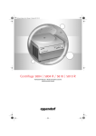
Centrifuge 5804 / 5804 R / 5810 / 5810 R
Instruction Manual · Mode d'emploi succinct
Instrucciones breves
Titel_Rueck_Klapp.fm Seite 3 Donnerstag, 18. Mai 2006 1:37 13
Centrifuge 5804 / 5804 R / 5810 / 5810 R
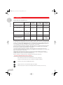
Shortcuts
Task / Function
Lid
Press
1. Select
Parameter set
time
or
speed
etc.
2. Select
or
1. Press repeatedly
Soft start / stop
time
2. Select ramp
or
Alarm ON / OFF
time
+
Display
Centrifuge
5804 /R / 5810 /R
Chapter in
instruction
manual
1. Selected
parameter
flashes.
3.5
3.8
2. New nominal
value appears.
Acceleration
ramp 9 (fast)...
0 (slow)
Deceleration
ramp 9...0
"alarm on"
3.11
3.19
speed
"alarm off"
Programming
(only during standstill)
1. Set parameter
2. Press 2 x
prog
3. Storing:
1. Parameter shown
2. "P..." symbolizes
first free
program no.
3.14
3. "ok"
prog
> 2 sec
At set rpm
start
stop
open
2
> 4 sec
on
off
3.12
Titel_Rueck_Klapp.fm Seite 2 Donnerstag, 18. Mai 2006 1:37 13
Centrifuge 5804 / 5804 R / 5810 / 5810 R
Figure 1 + 2
rpm
rcf
rad
short
prog
prog
accel
brake
rpm/rcf
min/sec
speed
time
open
start
stop
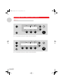
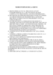
Fig. 1: Display field and control panel of the 5804 / 5810 (non-refrigerated)
rpm
rcf
rad
short
fast
temp
°C
temp
prog
prog
accel
brake
rpm/rcf
min/sec
speed
time
Fig. 2: Display field and control panel of the 5804 R / 5810 R (refrigerated)
3
open
start
stop
Titel_Rueck_Klapp.fm Seite 1 Donnerstag, 18. Mai 2006 1:37 13
Contents
Centrifuge 5804 / 5804 R / 5810 / 5810 R
Centrifuge 5804 / 5804 R / 5810 / 5810 R
Operating Instructions . . . . . . . . . . . . . . . . . . . . . . . . . . . . . . . . . . . . . . . . . . . . . . . . . . . . . . . . . . . . . . . . . . . . 5
Mode d’emploi succinct . . . . . . . . . . . . . . . . . . . . . . . . . . . . . . . . . . . . . . . . . . . . . . . . . . . . . . . . . . . . . . . . . . 26
Instrucciones breves. . . . . . . . . . . . . . . . . . . . . . . . . . . . . . . . . . . . . . . . . . . . . . . . . . . . . . . . . . . . . . . . . . . . . 32
No part of this publication may be reproduced without the prior permission of the copyright owner.
Copyright© 2005 Eppendorf AG, Hamburg
4
1B_5804_5810_US_en.fm Seite 5 Donnerstag, 18. Mai 2006 1:38 13
Centrifuge 5804 / 5804 R / 5810 / 5810 R
1
Contents
Introduction . . . . . . . . . . . . . . . . . . . . . . . . . . . . . . . . . . . . . . . . . . . . . . . . . . . . . . . . . . . . . . . . . . . . . . . . .
Delivery package. . . . . . . . . . . . . . . . . . . . . . . . . . . . . . . . . . . . . . . . . . . . . . . . . . . . . . . . . . . . . . . . . . . . . . .
Unpack . . . . . . . . . . . . . . . . . . . . . . . . . . . . . . . . . . . . . . . . . . . . . . . . . . . . . . . . . . . . . . . . . . . . . . . . . . . . . .
Installing the device . . . . . . . . . . . . . . . . . . . . . . . . . . . . . . . . . . . . . . . . . . . . . . . . . . . . . . . . . . . . . . . . . . . .
6
6
6
6
2
Safety regulations and applicational limitations . . . . . . . . . . . . . . . . . . . . . . . . . . . . . . . . . . . . . . . . . . . . 8
3
3.1
3.2
3.3
3.4
3.5
3.6
3.7
3.8
3.9
3.10
3.11
3.12
3.13
3.14
3.15
3.16
3.17
3.18
3.19
3.20
3.21
3.22
3.23
Operating . . . . . . . . . . . . . . . . . . . . . . . . . . . . . . . . . . . . . . . . . . . . . . . . . . . . . . . . . . . . . . . . . . . . . . . . . . 10
Operating controls . . . . . . . . . . . . . . . . . . . . . . . . . . . . . . . . . . . . . . . . . . . . . . . . . . . . . . . . . . . . . . . . . . . . . 10
Mounting / dismounting the rotors . . . . . . . . . . . . . . . . . . . . . . . . . . . . . . . . . . . . . . . . . . . . . . . . . . . . . . . . 10
Rotor lid F-45-30-11 . . . . . . . . . . . . . . . . . . . . . . . . . . . . . . . . . . . . . . . . . . . . . . . . . . . . . . . . . . . . . . . . . . . . 10
Loading the rotors. . . . . . . . . . . . . . . . . . . . . . . . . . . . . . . . . . . . . . . . . . . . . . . . . . . . . . . . . . . . . . . . . . . . . 10
Routine centrifugation with preset time / rcf display . . . . . . . . . . . . . . . . . . . . . . . . . . . . . . . . . . . . . . . . . . 12
Continuous operation . . . . . . . . . . . . . . . . . . . . . . . . . . . . . . . . . . . . . . . . . . . . . . . . . . . . . . . . . . . . . . . . . . 13
Short spin centrifugation (Short spin) . . . . . . . . . . . . . . . . . . . . . . . . . . . . . . . . . . . . . . . . . . . . . . . . . . . . . . 13
Time change during the run . . . . . . . . . . . . . . . . . . . . . . . . . . . . . . . . . . . . . . . . . . . . . . . . . . . . . . . . . . . . . 14
Refrigeration (for 5804 R/ 5810 R only). . . . . . . . . . . . . . . . . . . . . . . . . . . . . . . . . . . . . . . . . . . . . . . . . . . . . 14
Preset radius . . . . . . . . . . . . . . . . . . . . . . . . . . . . . . . . . . . . . . . . . . . . . . . . . . . . . . . . . . . . . . . . . . . . . . . . . 15
Centrifugation with Soft start / stop . . . . . . . . . . . . . . . . . . . . . . . . . . . . . . . . . . . . . . . . . . . . . . . . . . . . . . . 15
At set rpm . . . . . . . . . . . . . . . . . . . . . . . . . . . . . . . . . . . . . . . . . . . . . . . . . . . . . . . . . . . . . . . . . . . . . . . . . . . . 15
Preset program . . . . . . . . . . . . . . . . . . . . . . . . . . . . . . . . . . . . . . . . . . . . . . . . . . . . . . . . . . . . . . . . . . . . . . . 15
Programming . . . . . . . . . . . . . . . . . . . . . . . . . . . . . . . . . . . . . . . . . . . . . . . . . . . . . . . . . . . . . . . . . . . . . . . . 16
Write protection . . . . . . . . . . . . . . . . . . . . . . . . . . . . . . . . . . . . . . . . . . . . . . . . . . . . . . . . . . . . . . . . . . . . . . 16
Nominal value display . . . . . . . . . . . . . . . . . . . . . . . . . . . . . . . . . . . . . . . . . . . . . . . . . . . . . . . . . . . . . . . . . . 16
Automatic rotor recognition . . . . . . . . . . . . . . . . . . . . . . . . . . . . . . . . . . . . . . . . . . . . . . . . . . . . . . . . . . . . . 16
Display of elapsed spin time . . . . . . . . . . . . . . . . . . . . . . . . . . . . . . . . . . . . . . . . . . . . . . . . . . . . . . . . . . . . . 17
Switching on/off the warning signal . . . . . . . . . . . . . . . . . . . . . . . . . . . . . . . . . . . . . . . . . . . . . . . . . . . . . . . 17
Exiting the Service program . . . . . . . . . . . . . . . . . . . . . . . . . . . . . . . . . . . . . . . . . . . . . . . . . . . . . . . . . . . . . 17
Control via serial interface (optional). . . . . . . . . . . . . . . . . . . . . . . . . . . . . . . . . . . . . . . . . . . . . . . . . . . . . . . 17
Opening the centrifuge in the case of a power failure . . . . . . . . . . . . . . . . . . . . . . . . . . . . . . . . . . . . . . . . . . 17
Overload cutout switch / Fuses . . . . . . . . . . . . . . . . . . . . . . . . . . . . . . . . . . . . . . . . . . . . . . . . . . . . . . . . . . 17
4
4.1
4.2
4.3
4.4
4.5
4.6
4.7
Maintenance and cleaning . . . . . . . . . . . . . . . . . . . . . . . . . . . . . . . . . . . . . . . . . . . . . . . . . . . . . . . . . . . . 18
Device . . . . . . . . . . . . . . . . . . . . . . . . . . . . . . . . . . . . . . . . . . . . . . . . . . . . . . . . . . . . . . . . . . . . . . . . . . . . . . 18
The rotors . . . . . . . . . . . . . . . . . . . . . . . . . . . . . . . . . . . . . . . . . . . . . . . . . . . . . . . . . . . . . . . . . . . . . . . . . . . . 18
The aerosol-tight rotor . . . . . . . . . . . . . . . . . . . . . . . . . . . . . . . . . . . . . . . . . . . . . . . . . . . . . . . . . . . . . . . . . . 18
Rotor sterilization . . . . . . . . . . . . . . . . . . . . . . . . . . . . . . . . . . . . . . . . . . . . . . . . . . . . . . . . . . . . . . . . . . . . . . 18
Glass breakage . . . . . . . . . . . . . . . . . . . . . . . . . . . . . . . . . . . . . . . . . . . . . . . . . . . . . . . . . . . . . . . . . . . . . . . . 19
Refrigerated centrifuges . . . . . . . . . . . . . . . . . . . . . . . . . . . . . . . . . . . . . . . . . . . . . . . . . . . . . . . . . . . . . . . . . 19
Return of devices . . . . . . . . . . . . . . . . . . . . . . . . . . . . . . . . . . . . . . . . . . . . . . . . . . . . . . . . . . . . . . . . . . . . . . 19
5
Troubleshooting. . . . . . . . . . . . . . . . . . . . . . . . . . . . . . . . . . . . . . . . . . . . . . . . . . . . . . . . . . . . . . . . . . . . . . 20
6
Technical data . . . . . . . . . . . . . . . . . . . . . . . . . . . . . . . . . . . . . . . . . . . . . . . . . . . . . . . . . . . . . . . . . . . . . . 21
7
Ordering information . . . . . . . . . . . . . . . . . . . . . . . . . . . . . . . . . . . . . . . . . . . . . . . . . . . . . . . . . . . . . . . . . 22
Contents
1
1.1
1.2
1.3
5
1B_5804_5810_US_en.fm Seite 6 Dienstag, 24. Februar 2009 11:45 11
1 Introduction
1
Introduction
The Centrifuges 5804 / 5810 are non-refrigerated bench-top centrifuges and the Centrifuges 5804 R / 5810 R are
refrigerated bench-top centrifuges. The Centrifuges 5804 / 5804 R / 5810 / 5810 R are intended exclusively for use
indoors and are for separating aqueous solutions and suspensions of differing density in approved test tubes.
The 5804 / 5804 R models have a maximum capacity of 400 ml and the 5810 / 5810 R models have a maximum capacity
of 1600 ml.
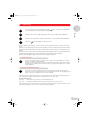
This sign is found on your centrifuge and on several pages in the operating manual.
Texts labeled with this sign contain safety notes. Read these safety precautions before using the
centrifuge for the first time.
Before starting up the Centrifuges 5804 / 5810 and 5804 R / 5810 R for the first time, please read the instruction
manual.
1.1 Delivery package
1 Centrifuge 5804 / 5810 with fan cooling or 1 refrigerated Centrifuge 5804 R / 5810 R (rotor not included with
centrifuges)
1 Main power cable (European standard plug)
1 Instruction manual
1 Rotor key
1.2 Unpack
When the machines are removed from the packaging, they must be supported by two persons near the rubber feet at the
bottom on the left- and right-hand side and then carried the short distance to the lab bench. Please observe the weightbearing capacity of the bench. If the machines are to be transported over long distances in the lab, a trolley must be
used.
1.3 Installing the device
For 5804 R and 5810 R only: To avoid damage to the compressor caused by incorrect transportation,
wait four hours after installation before switching on the device.
To disconnect the centrifuge from the power supply in the event of an error, an emergency switch must be installed away
from the centrifuge, preferably outside the centrifugation room or next to the exit of this room.
6
–
Place the centrifuge onto a horizontal, stable and resonance-free work surface.
–
Ensure that the working environment is well-ventilated and not exposed to direct sunlight.
–
There should be 15 cm clearance at the sides of the centrifuge and 10 cm to the rear.
–
According to the regulations of the EN 61010-2-020 standard, a safety distance of 30 cm must be observed around
the centrifuge during operation. No objects which cause damage when destroyed must be positioned in this space.
–
Before plugging in the centrifuge, compare your power supply with the electrical requirements listed on the identification plate.
The mains cable of the centrifuge may be connected only to a socket with a protective conductor.
–
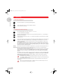
On refrigerated centrifuges 5804 R and 5810 R with a mains voltage of 120 V, a distinction is made between two
versions depending on requirements: the 15 A variant is equipped with a conventional IEC power cable (see Fig. 3) so
that these devices can be operated directly at the lab work-station using a conventional socket (120 V, 15 A).
However, this causes a drop in the cooling performance of this kind of device. This technical specification leads to a
rise in the lowest temperature which can be reached at maximum speed and to slower cooling down to the specified
value.
1B_5804_5810_US_en.fm Seite 7 Donnerstag, 18. Mai 2006 1:38 13
1 Introduction
1
Introduction
Fig. 3: 15 A IEC power cable
Fig. 4: 20 A standard variant
On the 20 A standard variant, by contrast, the power cable is permanently attached to the device (see Fig. 4). These
devices have a special 20 A plug and require the appropriate socket to guarantee the supply of current and voltage
required for the centrifuges (120 V, 20 A). The advantage is greater, more rapid cooling.
–
To switch on the centrifuge, press the mains switch (on the right-hand side of the device). The nominal values of the
test run appear in the display and the control lamp in the Open key lights up.
–
The centrifuge lid can be opened by pressing the Open key.
Please insert the rotor before starting and tighten it with the supplied rotor key.
The rotors A-4-81 and A-4-81-MTP are tightened with the special rotor key included in the rotor delivery package.
7
1B_5804_5810_US_en.fm Seite 8 Donnerstag, 18. Mai 2006 1:38 13
2 Safety regulations and applicational limitations
2
In the interests of your own personal safety, always observe the following regulations:
The rotor and the rotor cover must always be securely fastened.
Safety regulations and applicational limitations
Do not begin centrifugation before the rotor has been securely fastened.
The rotor must be loaded symmetrically. Opposing tubes should be of the same type and should be filled equally.
For reasons of mechanical stabilization, all positions of rotor A-4-44 and A-4-62 / A-4-62-MTP must be loaded with
buckets of the same type.
Prior to centrifugation, the tubes should in any case be visually inspected for material damage. Damaged tubes may not
be centrifuged. This is because broken tubes can, in addition to sample loss, result in further damage to the centrifuge
and accessories.
Do not use buckets and rotors which show clear signs of corrosion or mechanical defects. Please check accessories at
regular intervals.
Do not operate centrifuges which have not been correctly installed or repaired.
Do not move or knock against the centrifuge during operation.
Repairs must only be performed by an Eppendorf authorized service technician.
Only use original rotors and spare parts recommended by Eppendorf.
The Centrifuges 5804 / 5810 and 5804 R / 5810 R may only be used for special applications. They must not be operated
in a hazardous or flammable environment and must not be used to centrifuge explosive or highly reactive substances.
If such liquids are spilled in the rotor or rotor chamber, the centrifuge must be cleaned with a moist cloth and a mild soap
solution.
A liquid density of 1.2 g/ccm must not be exceeded at the maximum rotational speed.
During longer spin times in the 5804 / 5810 models, the sample tubes may heat up. Observe the limiting data specified
by the tube manufacturer.
The use of organic solvents (e.g. chloroform) may have an adverse effect on the stability of plastic test tubes.
Following operation in a cooling room, run the centrifuge for 30 minutes in the cooling room until it is warm. Alternatively,
allow it to warm up in a lab for at least three hours, but do not plug in the centrifuge in order to prevent damage caused
by condensation.
Rotors are high-grade components which are subject to extreme mechanical strain. Aluminium rotors are protected
against corrosion caused by commonly-used laboratory chemicals by means of an electrolytic coating, although this
protection cannot be fully guaranteed.
Please ensure that the rotor is protected from mechanical damage. Even slight scratches and cracks can cause severe
inner damage to the rotor materials, which are difficult or impossible to detect with the eye.
Please avoid using aggressive chemicals with the rotors. Such chemicals include concentrated and mild alkalis,
concentrated acids, solutions containing mercury ions, copper ions and other heavy-metal ions, chlorinated
hydrocarbons and concentrated saline solutions.
When handling toxic or radioactive liquids or pathogenic bacteria out of Risk Group II (see World Health Organization:
"Laboratory Biosafety Manual"), observe national regulations.
In the event of contamination caused by impurities or aggressive agents, the rotor must be cleaned immediately using a
neutral cleaning liquid. This is particularly important for the bores of the fixed-angle rotor and for the buckets.
Please clean your rotor regularly using a neutral cleaning liquid (e.g. Extran® neutral or RBS neutral). This will protect the
rotor and prolong its service life.
According to EN 55011, the centrifuges 5804/5804 R and 5810/5810 R are Class A products. Interference with
signal reception can occur in residential areas. The operator should take appropriate protective measures.
8
1B_5804_5810_US_en.fm Seite 9 Donnerstag, 18. Mai 2006 1:38 13
2 Safety regulations and applicational limitations
2
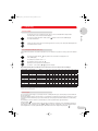
The following rotors and accompanying buckets have a maximum operating life of seven years. The date of production is
engraved on the rotor in four-digit form (e.g. 10/98 = October 1998):
5804 730.003
A-4-62-MTP
5810 711.002
A-2-DWP
5804 740.009
T-60-11
5804 730.003
F-34-6-38
5804 727.002
A-4-81
5810 718.007
A-4-62
5810 709.008
A-4-81-MTP
5810 725.003
Safety regulations and applicational limitations
A-4-44
12 1
98
11
5
6
2 3 4
8 9 10
Transparent rotor lids made of PC and PP as well as the PC caps of the rectangular buckets have an operating life of
three years. The date of production is engraved in the form of a clock
.
7
Contact with organic solvents (e.g. phenol, chloroform) may have an adverse effect on the transparent (polycarbonate)
caps of the aerosol-tight rotors. Please check lids of this type regularly for chemical damage or for cracks. Cracked caps
or caps with a milky discoloration must be replaced immediately.
Do not use rotors, caps or buckets which have been subjected to chemical or mechanical damage
or which have exceeded their maximum operating life!
* PC = Polycarbonate; PP = Polypropylene
9
1B_5804_5810_US_en.fm Seite 10 Donnerstag, 18. Mai 2006 1:38 13
3 Operating
3
3.1 Operating controls
Operating
See the fold-back cover at the front of this manual.
In the text,
prog
,
time
,
speed
, etc. signify keys
"Buckets" include buckets and titer plate buckets.
3.2 Mounting / dismounting the rotors
A summary of the various different rotors can be found in the brochure.
Clean the motor axle and the rotor bores with a cloth before attaching the rotor.
– When fastening / loosening the rotor onto / from the motor axle, ensure that the temperature of the rotor and the
motor axle is between 10 °C and 30 °C.
– Mount the rotor onto the motor axle and tighten the rotor nut by turning clockwise using the appropriate rotor key
supplied.
– To dismount the rotor, turn the rotor nut counterclockwise using the rotor key.
– When the rotors are not in the centrifuge, please place them in the rotor stand (Order no. 5804 720.008).
– Do not centrifuge using rotors and buckets with visible corrosion or mechanical defects (see Chapter 2: Safety regulations and applicational limitations ).
The Centrifuges 5804 / 5810 and 5804 R / 5810 R have automatic rotational speed limitation.
3.3 Rotor lid F-45-30-11
The non-aerosol-tight rotor lid of the rotor F-45-30-11 is attached by pressing the lid onto the rotor. The rotor lid need not
be screwed tight.
3.4 Loading the rotors
The rotors and buckets must always be loaded symmetrically. The adapters may only be loaded with the test tubes
recommended.
Differences in the weight of the filled sample tubes should be kept as low as possible in order to prolong the life-time of
the drive and to minimize running noises caused by imbalance.
On each rotor you will find information concerning the maximum weight of a completely loaded bucket (bucket
including adapter, tubes and liquid or titer plate buckets including titer plate and liquid) (see also applicational
limitations).
Performance data of the rotors
Type
Designation
max. capacity
(ml)
max. rotational
speed rpm /
max. rcf (x g)
max.
Radius
(cm)
5804 /
5804 R
5810 /
5810 R
Aerosol-tight
centrifugation
possible
A-4-81 1)
4 x 400 ml
4,000 / 3,250
18.0
–
●
●
A-4-81 1) 3)
96 x 2 ml
4,000 / 2,600
14.6
–
●
–
A-4-81-MTP 1)
16 x MTP-Platte
4,000 / 2,900
15.3
–
●
–
A-4-62 2)
4 x 250 ml
4,000 / 3,200
18.0
–
●
●
Swing-bucket rotors
A-4-62-MTP 2)
16 x MTP-Platte
4,000 / 2,750
15.4
–
●
–
A-4-44
4 x 100 ml
5,000 / 4,500
16.1
●
●
●
A-2-DWP
4 x Deepwell-Platte
3,700 / 2,250
14.7
●
●
–
Fixed-angle rotors
F-34-6-38
6 x 85 ml
11,000 / 15,550
11.5
●
●
–
F-34-6-38
6 x 85 ml
12,000 / 18,500
11.5
–
only 5810 R
–
F-45-30-11
30 x 2 ml
14,000 / 20,800
9.5
●
●
–
FA-45-30-11
30 x 2 ml
14,000 / 20,800
9.5
●
●
●
F-45-48-PCR
6 x 8er PCR-Streifen
12,000 / 15,350
9.5
●
●
–
60 x 2 ml
14,000 / 16,400
7.5
●
●
–
Drum rotor
T-60-11
10
1B_5804_5810_US_en.fm Seite 11 Donnerstag, 18. Mai 2006 1:38 13
3 Operating
3
1) The swing-bucket rotor can be delivered without buckets, equipped with rectangular buckets as an A-4-81 or with MTP buckets as an
A-4-81-MTP, whereby the flex buckets (especially MTP-buckets) can be purchased extra in sets of 2 or 4, user-friendly change of rectangular
buckets or MTP and flex buckets is guaranteed by the use of a common rotor cross.
2) The swing-bucket rotor can be delivered as A-4-62 (loaded with buckets) or as A-4-62-MTP (loaded with microtest plates). User-friendly
Operating
exchange of rectangular buckets or microtest plate buckets is guaranteed by the use of all-in-one rotor cross.
3) A-4-81 is equipped with flex buckets and IsoRack adapters.
Swing-bucket rotor
Only the combinations of rotor/buckets/adapter which are recommended by the manufacturer
may be used.
Please check whether all buckets have been inserted correctly and can swing freely.
For purposes of mechanical stabilization, all positions of the rotors A-4-44 and A4-62 / A-4-62-MTP must be loaded with
the same buckets. In contrast, the rotor A-4-81 / A-4-81-MTP can be equipped with a mix of rectangular buckets and
titer plate buckets. It is in principle not permitted to use swing-bucket rotors with only two rectangular buckets or titer
plate buckets inserted.
Fig. 5: Rotor A-4-81-MTP symmetrically
loaded
Fig. 6: Not allowed, because the pegs are not evenly
loades, rotor is asymmetrically loades
The rectangular buckets are sorted according to weight. The weight category is printed on the side in the groove:
e.g. 86 (the last two places in grammes). Opposing buckets should be of the same weight category. When placing
follow-up orders, please state the weight category. This also applies to titer plate buckets.
Ensure that the grooves are clean before inserting the buckets. Unclean grooves and pivots prevent the buckets from
swinging freely.
When working with a rotor which is not completely loaded, position the tubes within the buckets in such a way that the
rotor pivots are stressed evenly.
Fig. 7: Rotor is symmetrically loaded
Fig. 8: Not permitted: pivots are not stressed
evenly, rotor is not symmetrically loaded
A manual swing test with empty tubes must be carried out if oversized tubes
(i.e. longer than 100 mm) are used.
11
1B_5804_5810_US_en.fm Seite 12 Donnerstag, 18. Mai 2006 1:38 13
3 Operating
3
Operating
Permitted loads for the swing-bucket rotor
Rotor
A-4-44
(4 x 100 ml)
Maximum load per
100 ml rectangular bucket
310 g
(adapter + tubes)
Maximum load per
plate carrier
–––
Maximum load per 50 ml
Falcon® bucket
144 g
(for two conical
tubes incl. liquid
and form insert)
Specifications on the rotor
(weight for loaded buckets /
rectangular buckets)
4 x 0.6 kg
A-2-DWP
(Deepwellplate rotor)
A-4-62
(4 x 250 ml)
A-4-62-MTP
A-4-81
(4 x 400 ml)
A-4-81-MTP
–––
630 g
(adapter + tubes)
780 g
(adapter + tubes)
380 g
380 g
380 g
(with full plates)
(with full plates)
(with full plates)
–––
–––
–––
2 x 1.010 kg
4 x 1.1 kg
4 x 1.4 kg
(A-4-81)
4 x 1.22 kg
(A-4-81-MTP)
The weight specifications printed on the rotor (e.g. 4 x 0.6 kg for the 4 x 100 ml swing-bucket rotor A-4-44) correspond to
the overall weight of the rectangular bucket, inclusive of adapter, test tubes and the contents of each individual position.
In general, commercially-available deepwell plates with a 96-well plate format may only be used in the buckets of the
A-4-62-MTP on condition that the maximum load does not exceed 380 g and the maximum height of the plate does
not exceed 53 mm. This restriction also applies to stacked titer plates or culture plates.
Commercially available deepwell plates or filter plates / filter plate stacks in the 96-well plate format may be inserted in
the buckets of the A-2-DWP only if their load does not exceed 380 g and their height does not exceed 89 mm.
These restrictions also apply to stacked titer plates or culture plates.
Commercially available deepwell plates or filter plates / filter plate stacks may be inserted in the buckets of the
A-4-81-MTP only if their load does not exceed 380 g and their height does not exceed 60 mm. These restrictions also
apply to stacked titer plates or culture plates.
If deepwell plates used with dimensions which do not correspond to the values stated above (e.g. prototypes,
combination plates with a heavy lid or specially designed plates), the user must consult Eppendorf to establish the
suitability of using these plates in a titer plate or Deepwell plate rotor.
Under no circumstances use MTP-, MTP / Flex- and DWP-buckets with deformed side plates.
3.5 Routine centrifugation with preset time / rcf display
Turn on the main power switch. The nominal values of the last run are displayed.
Load the rotor symmetrically and close the centrifuge lid. The Open key lights blue.
speed
activates the preset speed. The SPEED display flashes.
modify the values. The new nominal value appears in the display.
If the preset speed is in rcf, please check the radius that has been entered. (see Section 3.10).
12
1B_5804_5810_US_en.fm Seite 13 Donnerstag, 18. Mai 2006 1:38 13
3 Operating
3
speed
to select rcf, press this key repeatedly until the rcf symbol ( ) appears to the left of the SPEED display.
The rcf value flashes and can be modified using the arrow keys.
activates the preset time. The TIME display flashes. The time can be modified using the arrow keys.
temp
activates the preset temperature. The nominal temperature in °C can be modified using the arrow keys.
start
stop
starts the run.
Operating
time
flashes and displays the rotation of the rotor.
Rotor recognition (see also Chapter 3.16) occurs at 200 to 700 1/min and the device then accelerates to the nominal
speed.
During the run, the rotational speed of the rotor or the appropriate rcf value, the sample temperature and the remaining
spin time in minutes are displayed. The last minute is counted down in seconds. During the run, all parameters can be
modified.
After the end of a run, or after a run has been interrupted by pressing the Stop key, the rotor is braked and brought to a
standstill. During the braking process, the time display flashes and the elapsed spin time is displayed.
When the lamp in the Open key lights up, the lid can be unlocked by pressing the key.
3.6 Continuous operation
time
The continuous operation function is set above 99 min or below 1 min using the arrow keys. In the time
display, "oo" indicates continuous operation.
During the run, the actual rotational speed/ RCF and temperature values and the elapsed time in minutes
are displayed. If the centrifuge runs for more than 99 min, "99." appears in the display. The run is ended
with the STOP key.
3.7 Short spin centrifugation (Short spin)
short
Press for as long as the run should last. The text "SH" will appear in the display. The elapsed time is
displayed in seconds. An already interrupted run can be continued up to two times by repeatedly pressing
the key, as long as the centrifuge has not yet come to a stillstand.
If the Short key is pressed while the lid is open, one of the following two status signs will appear, depending upon the
rotor recognized (see Chapter 3.16 Automatic rotor recognition): "rpm max" or "200 – rpm"
The status displays mean:
"rpm max":
The inserted rotor accelerates to its nominal rotational speed.
"200 – rpm":
The maximum rotational speed for the short-spin run can be set over the arrow keys.
If the Short key is pressed for longer than three seconds while the centrifuge lid is open, the device will switch over to the
other status and display it for two seconds. The status set last will be maintained.
13
1B_5804_5810_US_en.fm Seite 14 Donnerstag, 18. Mai 2006 1:38 13
3 Operating
3
3.8 Time change during the run
Operating
time
Press this key during the run (not during the braking phase).
change the duration of the run. The time elapsed is taken into
account in the new actual value.
3.9 Refrigeration (for 5804 R / 5810 R only)
temp
The nominal temperature value can be set from – 9 °C to + 40 °C.
It can be modified during centrifugation.
Once the nominal temperature value has been reached, a deviation greater than ± 3 °C is indicated by a
flashing temperature display.
If the temperature deviates by more than 5 °C, a periodic warning signal can be heard and the centrifuge
switches itself off.
fast
temp
starts a temperature run at a rotor-specific speed for the best possible refrigeration. The new preselected
temperature is quickly attained in the rotor by cooling. FT appears in the PROG field. The run is then
ended automatically at the arrived at nominal temperature or by pressing the Stop key. A signal can be
heard at regular intervals.
The centrifuge does not terminate the run until the rotor, carrier or rectangular bucket have reached the
pre-selected temperature. The target temperature is initially measured on the chamber and then shown in
the display. However, the temperature run is automatically terminated when the rotor, carrier or rectangular
bucket have reached the target temperature.
When the lid is closed, the rotor chamber is refrigerated to the preselected nominal temperature before or
Standbyrefrigeration after a run, as long as this value is below ambient temperature. The rotor does not turn during this
procedure and the temperature changes more slowly.
If the centrifuge is not used for longer than 8 hours, or if the lid is not opened for this time, the refrigeration
function switches off for safety reasons. Standby off appears in the display, together with the nominal
temperature in the rotor chamber. The desired temperature can be reached rapidly via the Fast Temp
function.
The standby cooling of the centrifuge can also be switched on permanently. To do this the Temp and Prog
keys must be pressed simultaneously. Standby 8h appears in the display. Following this, the Fast temp
must be pressed immediately in order to switch the standby cooling over into permanent operation.
Standby endless appears in the display.
The standby cooling is automatically switched off after 8 hours in order to protect the device.
The switching of standby cooling to permanent operation is carried out at own risk and can lead
to overheating of the compressor.
Please empty and clean the tray for condensation water (on the right at the bottom of the device) on a
regular basis.
Remove any condensation water and ice regularly from the rotor chamber using a soft, moist
cloth. Defrosting is recommended for ice removal.
14
1B_5804_5810_US_en.fm Seite 15 Donnerstag, 18. Mai 2006 1:38 13
3 Operating
3
3.10 Preset radius
Operating
The internal conversion of rotational speed to RCF occurs as a standard with the largest radius
A smaller radius can be entered for another adapter.
Press this key repeatedly until the radius symbol ( ) appears to the left of the SPEED display.
The radius value flashes.
speed
change the values entered. The new rcf value appears three seconds (or 10 s during the stillstand) after the
rotor radius has been entered.
3.11 Centrifugation with Soft start / stop
If the maximum acceleration / deceleration speed (level 9) is not desired, it is possible to set the speeds in nine different
levels.
Press this key repeatedly until
to the TIME display
time
(the symbol for the acceleration levels) appears next
Presetting the acceleration level 9 – 0.
Deceleration is set in the same way
.
Braking level 0 corresponds to free deceleration.
For levels 0 – 8, the symbols
appear in the display.
Approximate braking times for different rotors for the levels 0 to 9 (in seconds) for 230 V centrifuges
5804 / 5804 R
5810 / 5810 R
Rotor
0
1
2
3
4
5
6
7
8
9
–
–
●
A-4-81
532
189
174
143
131
109
95
85
59
31
●
A-4-81-MTP / Flex
643
191
174
142
131
110
94
83
58
30
–
●
A-4-62
740
190
170
140
130
110
95
85
55
26
–
●
A-4-62-MTP
620
190
170
140
130
110
95
85
55
26
●
●
A-4-44
470
300
270
220
200
140
100
75
45
23
●
●
A-2-DWP
304
174
130
118
100
75
51
44
32
14
●
●
T-60-11
800
280
140
95
70
55
45
40
36
36
●
●
F-34-6-38
880
370
280
190
170
150
125
95
75
54
●
●
F-45-30-11
240
140
70
45
35
30
25
22
19
18
●
●
FA-45-30-11
240
140
70
45
35
30
25
22
19
18
●
●
F-45-48-PCR
169
119
60
41
31
26
22
19
17
16
The given times are to be considered guidelines. While level 9 means "strongest braking", level 0 means "free deceleration", whereby considerable
fluctuations can occur with this uncontrolled deceleration depending upon the condition of the device and the load. The deceleration times for the 230 V
and 120 V devices are almost identical.
3.12 At set rpm
The "at set rpm" function triggers a counting down of the centrifugation time upon achieving the preselected rotational
speed ("at set rpm").
Pressing the START / STOP key for longer than 4 seconds while the centrifuge lid is open triggers a switching over to the
"at set rpm" function. While the key is pressed, both triangles of the pictogram are illuminated in blue in an alternating
sequence.
The activated "at set rpm" function is symbolized by the continuously illuminated, upper blue triangle
in the pictogram
.
In order to leave the "at set rpm" function again, and thus to activate the countdown of the centrifugation time directly
after switching on the centrifuge, press the START / STOP key while the centrifuge lid is open. The standard setting is
selected again after 4 seconds, symbolized by the illumination of the lower triangle in the pictogram
.
15
1B_5804_5810_US_en.fm Seite 16 Donnerstag, 18. Mai 2006 1:38 13
3 Operating
3
3.13 Preset program
Operating
Programs can only be preselected when the device is at a standstill.
prog
Press this key once ➔ the program no. that has been set flashes.
0
Data from last run.
1...9, A...Z Fixed programs.
select further program numbers.
start
stop
Returns to program 0 or leaves the programming mode when the lid is open.
In order to start the selected program immediately, the centrifuge lid must be closed prior to
pressing the START / STOP key.
3.14 Programming
Storing a fixed program (only possible when the device is at a standstill):
It is possible to save a maximum of 35 fixed programs (1...9, A...Z).
Enter the program data to be used first by pressing the parameter keys and the arrow keys or use the data from the last
run. The "at set rpm" functions and the set deceleration ramp can also be saved in a program if necessary.
prog
Press this key twice ➔ the first free program no., indicated by "P...", appears in the display and
flashes.
The desired free program number (1...9, A...Z) can be selected.
prog
Hold down this key for two seconds until ok appears in the display. The previously set parameters
of Temp., Speed, Time, etc. are now saved as a data set.
If parameters are modified during the run with a fixed program, "0" appears in the PROG field and the user exits the
program without it being modified.
To exit the fixed program, call up program "0" or modify the parameters.
3.15 Write protection
In order to avoid accidental deletion of an existing fixed program, the old data set must be deleted while the lid is open
prior to renewed assignment of a program number:
prog
Press this key once ➔ the program no. display flashes.
select the program no. which is to be deleted.
start
stop
16
Press this key within ten seconds until cleared appears.
1B_5804_5810_US_en.fm Seite 17 Donnerstag, 18. Mai 2006 1:38 13
3 Operating
3
3.16 Nominal value display
Operating
All nominal values are displayed when the centrifuge is at a standstill. During a run, all nominal values can be displayed
for 2.5 seconds by pressing one of the parameter keys (Temp, Speed, Time).
3.17 Automatic rotor recognition
Automatic rotor recognition occurs at the beginning of each run.
When a new rotor is recognized, the maximum rotational speed appears in the display for two seconds.
If the nominal speed set is greater than the maximum speed for the rotor used, it is aligned to the maximum speed and
the run is interrupted. SPEED appears in the display and the run must be restarted.
The rotational speed and the radius for the rcf value will be reset to the maximum permitted value.
If a run with a program has been started, the program number is set to "0".
3.18 Display of elapsed spin time
time
prog
If the Time key and the Prog key are pressed simultaneously, the total running time (in hours) of the
centrifuge appears in the display. This function can only be selected when the rotor is at a standstill.
3.19 Switching on/off the warning signal
speed
time
Press the Speed and Time keys simultaneously. "Alarm on" and "Alarm off" appear after 2 seconds
alternately in the display.
3.20 Exiting the Service program
If the Service program has been selected accidentally, press both arrow keys simultaneously.
3.21 Control via serial interface (optional)
All centrifuge functions can be operated via the serial interface (RS 232). The appropriate conversion must be carried out
by the service department.
Only devices which have been tested in accordance with IEC 950 may be connected via the serial interface.
3.22 Opening the centrifuge in the case of a power failure
If the magnetic lid latch cannot be activated because of a power failure, the emergency lid release can be activated
manually:
Turn off the main power switch. Wait until the rotor has come to a standstill (The rotor may continue spinning for
up to eight minutes). Insert the standard rotor key into the opening in the middle of the front part in the nut
underneath and turn counter-clockwise. This disengages the lid, allowing it to be opened.
Be absolutely sure to remove the rotor key afterwards.
3.23 Overload cutout switch / Fuses
The 230 V and 120 V devices have built-in thermal overload switches which function as all-pole fuses. When the
overload protection is actuated, these switches over the power switch to OFF, but do not switch it on again
automatically.
To turn on the overcurrent protector switch again, please turn off the centrifuge for 10 seconds with the mains power
switch. When the centrifuge is subsequently turned on again, the overcurrent protector switch will be automatically
reactivated.
17
1B_5804_5810_US_en.fm Seite 18 Donnerstag, 18. Mai 2006 1:38 13
4 Maintenance and cleaning
4
4.1 Device
Maintenance and cleaning
The outside of the centrifuge and the rotor chamber should be cleaned regularly with neutral
detergent. This is for hygiene purposes as well as to prevent contamination caused by residual
contamination.
The user is responsible for cleaning or decontaminating the centrifuge in the event of contamination caused
by high-risk substances.
Open the lid of the centrifuge and disconnect the main power plug. Unscrew the rotor with the rotor key provided and
clean separately. Only neutral agents may be used for cleaning and disinfection (e.g. diluted Extran® neutral, RBS
neutral or 70 % isopropanol/water mixture or an alcohol-based disinfectant). The rotor chamber should only be cleaned
with a moist cloth.
After cleaning with detergent, the rubber seals in the rotor chamber should be rinsed well with water and lubricated with
glycerine in order to prevent the seals from becoming brittle.
If condensation water forms in the rotor chamber after freezing occurs, dry with a soft absorbent cloth.
The user must consult the manufacturer before cleaning or decontaminating the centrifuge using methods not
recommended by the manufacturer in order to ensure that the centrifuge and accessories are not damaged. To ensure
that the centrifuge functions correctly and safely in the long-term, please note that aggressive chemicals can damage the
rotor, buckets and boiler. Please check the centrifuge regularly for damage caused by corrosion.
4.2 The rotors
The rotor and buckets must be cleaned regularly to prevent contamination caused by residue. Check at least the rotor
and housing monthly for residue and corrosion. This applies in particular to the rotor bores. Please clean your rotor using
a neutral cleaning liquid. This will protect the rotor and prolong its service life. As a reminder, the message "clean rotor"
appears in the display of the centrifuge three times after every 200 runs.
When using the swing-bucket rotor, ensure that the grooves in which the buckets are fitted are free of contamination. The
buckets can be lubricated with the lubricant (grease for pivots) supplied, although care must be taken to ensure that the
buckets can still swing freely.
4.3 The aerosol-tight rotor
The sealing rings of the aerosol-tight rotor FA-45-30-11 are subject to natural wear and tear and should be replaced
regularly if damaged. To protect the rotor, please ensure that the sealing rings are maintained regularly.
When handling the rotor lid, please observe the specifications regarding the chemical resistance of the materials of
construction.
The cover of the aerosol-tight rotor must not be fastened tightly during storage!
4.4 Rotor sterilization
All rotors are autoclavable (121 °C, 20 min).
After the rotor has been autoclaved ten times, the lids of the aerosol-tight buckets or rotors must be exchanged.
The aerosol-tight Rotor FA-45-30-11 and the lid can be autoclaved at 142 °C for 2 hours to destroy prions, but the
aerosol-tight lid must be exchanged after each autoclaving.
18
1B_5804_5810_US_en.fm Seite 19 Donnerstag, 18. Mai 2006 1:38 13
4 Maintenance and cleaning
4
4.5 Glass breakage
Maintenance and cleaning
When centrifuging glass tubes, please observe that high speeds/rcf’s increase the risk of glass breakage. Please follow
the manufacturer’s instructions concerning the maximum speed/rcf of centrifuge tubes. In the event of glass breakage,
carefully remove all splinters and all ground glass from the rotor, the buckets, the adapters and the rotor chamber. You
may need to replace the rubber mats and adapters to prevent further damage.
Fine splinters of glass may otherwise scratch the surface of the rotors and buckets, reducing their resistance to
chemicals. The air turbulences within the rotor chamber produce a very fine black powder of abraded metal. In addition
to causing damage to the rotor chamber, rotor, buckets and adapters, the powder also contaminates the samples.
Check the rotor bores regularly for residues and damage.
4.6 Refrigerated centrifuges
Clean the refrigeration mesh of the heat exchanger (on the rear side of the device) with a brush at least twice a year.
Be sure to first switch off the centrifuge and pull the plug.
Switch off the centrifuge after use, leave the lid open and empty the tray for condensation water, situated below the
device on the front right-hand side.
4.7 Return of devices
When returning centrifuges, please ensure that the devices have been decontaminated and thereby do not present a
health risk to our Service staff.
You will find additional information and a blank of the decontamination confirmation at www.eppendorf.com.
Do also consult your laboratory safety officer about a suitable decontamination method.
Please fill out the decontamination confirmation and place it together with the device when it is to be sent back to
Eppendorf.
19
1B_5804_5810_US_en.fm Seite 20 Donnerstag, 18. Mai 2006 1:38 13
5 Troubleshooting
5
Troubleshooting
Centrifuges 5804 / 5810 and 5804 R / 5810 R
Error
Display
Cause
Solution
No display.
None
No main power connection.
Check power supply cable.
Power failure.
Check main power fuse on the device and
in the laboratory.
clean rotor
Standby off
200 runs.
Centrifuge not used for 8 hours.
Clean rotor and drum.
Open lid and then close it again.
Centrifuge does not
start up.
no rotor
No rotor.
Error in the drive or rotor
recognition.
Mount rotor.
Switch off the device and switch it on
again.
Lid cannot be
opened.
None
Power failure.
Bring rotor to a standstill, activate
emergency lid release.
Lid not closed
completely.
Press Open
Close Lid
Lid latch not engaged.
Lid not closed correctly.
Press Open and close lid again.
Press down lid.
Lid does not open.
Lift Lid
Lid does not open automatically.
Open lid manually.
Centrifuge shakes
during acceleration
and switches off.
IMBAL
Rotor not loaded symmetrically.
Check rotor equipment and rotor load.
ROTOR
Rotor not fastened.
Fasten rotor correctly.
Device has been moved or work
surface unstable.
Place device on stable work surface.
SPEED
Nominal speed for rotor too high.
Enter new nominal speed.
Error 1
Rotor is not recognized.
Repeat run. If error recurs, test with
another rotor.
Centrifuge switches
off.
Problem with the rotational speed
measuring system.
Centrifuge switches
off. Warning signal.
Flashing
temperature display.
Error 2
Imbalance sensor damaged.
Error 3
Problem with the rotational speed Leave device switched on for 8 min, press
measuring system.
Open, then open the device. Repeat run.
Error 4
Lid latch sensor damaged.
Switch device off and then switch it on
again. Repeat run.
Error 5
Unauthorized opening of lid or lid
switch damaged.
Repeat run.
overload
or
Error 6
Converter overloaded.
Brake defective.
Voltage supply too low.
Rotor becomes loose.
Allow to cool. Restart device after 5 min.
Error 7
Overspeed.
Repeat run.
Error 8
Rotor loose.
Drive error.
Motor defective.
Tighten rotor.
overtemp
Temperature deviation from
nominal value > 5°C.
Repeat run.
Error 9–25
Electronics error.
Clear Memory
Program memory full.
Delete several programs or press Start or
Prog to begin new run.
Interrupt
Power failure during the run.
Restart.
Temperature deviation from
nominal value > 3 °C.
If the above solutions are unsuccessful, please contact SERVICE.
20
Repeat run.
Check voltage supply.
Tighten rotor.
1B_5804_5810_US_en.fm Seite 21 Donnerstag, 18. Mai 2006 1:38 13
6 Technical data
5804 / 5804 R
5810 / 5810 R
Power supply:
230 V / 50 or 60 Hz
230 V / 50 or 60 Hz
Maximum power requirement:
5804 / 5810
5804 R / 5810 R
900W
1650 W
900 W
1650 W
Fuse protection:
5804 / 5810
5804 R / 5810 R
Excess current switch 12 A
Excess current switch 12 A
Excess current switch 12 A
Excess current switch 12 A
Max. rotational speed:
14 000 rpm
14 000 rpm
Max. centrifugal force:
20 800 rcf
20 800 rcf
Max. kinetic energy:
5804 / 5810
5804 R / 5810 R
19 000 Nm (11 000 rpm)
19 000 Nm (11 000 rpm)
19 000 Nm (11 000 rpm)
23 000 Nm (12 000 rpm)
Max. load:
4 x 100 ml
4 x 400 ml
Max. density of material
to be centrifuged:
1.2 g/ml
1.2 g/ml
Permitted ambient temperature
during operation:
5804 / 5810
5804 R / 5810 R
2 °C to 40 °C
15 °C to 35 °C
2 °C to 40 °C
15 °C to 35 °C
Permitted maximum relative air humidity:
75 %
75 %
Degree of contamination
2
2
Overvoltage category
II
II
Standardized interface (optional)
RS 232 C
RS 232 C
Noise level
< 65 dB (A)
< 65 dB (A)
466 x 496 x 337 mm
(D = 550 with operating
section)
535 x 536 x 345 mm
(D = 608 with operating
section)
634 x 496 x 342 mm
(D = 550 with operating
section)
700 x 536 x 345 mm
(D = 608 with operating
section)
55 kg
80 kg
68 kg
99 kg
Power supply:
120 V / 60 Hz
120 V / 60 Hz
Maximum power requirement:
5804 / 5810
5804 R / 5810 R, 20 A version
5804 R / 5810 R, 15 A version
950 W
1650 W
1300 W
950 W
1650 W
1300 W
Fuse projection in the device:
5804 / 5810
5804 R / 5810 R, 20 A version
5804 R / 5810 R, 15 A version
Excess current switch 12 A
Excess current switch 18 A
Excess current switch 15 A
Excess current switch 12 A
Excess current switch 18 A
Excess current switch 15 A
Dimensions (W x D x H):
5804 / 5810
5804 R / 5810 R
Weight:
5804 / 5810
5804 R / 5810 R
6
Technical data
Centrifuges
Electrical data for 120 V model
Technical specifications subject to change!
21
1B_5804_5810_US_en.fm Seite 22 Donnerstag, 18. Mai 2006 1:38 13
7 Ordering information
7
Ordering information
Centrifuge 5804
Bench-top centrifuge, max. capacity 4 x 100 mL
with rotational speed regulation up to 14,000 rpm
120 V / 60 Hz, not including rotor
230 V / 50 – 60 Hz, not including rotor
Centrifuge 5804 R
Refrigerated bench-top centrifuge, max. capacity 4 x 100 mL
with rotational speed regulation up to 14,000 rpm
Temperature range: – 9 to 40 °C
120 V / 60 Hz, not including rotor
230 V / 50 – 60 Hz, not including rotor
Other voltages or 50 Hz frequency upon request.
22622501
22622552
22623508
22623559
Captain Eppi, Rotor key holder, 1 piece
Captain Eppi, Rotor key holder, 10 pieces
22639609
22639625
Rotor stand, for all rotors for Centrifuges 5804 5804 R / and 5810 / 5810 R
22639021
Swing-bucket rotor and accessories (see brochure for further details) for Centrifuge 5804 / 5804 R
Swing-bucket rotor A-4-44 (4 x 100 mL),
with 4 rectangular buckets of 100 mL
22637401
1 rectangular bucket of 100 mL with weight category (for individual deliveries,
please state the existing weight category)
22637410
2 aerosol-tight caps for 100 mL rectangular bucket
22637428
4 replacement seals for aerosol-tight caps of the rectangular bucket 100 mL
22637444
Adapters for standard test tubes, blood withdrawal systems and micro test tubes
for 100 mL rectangular bucket
(Number and diameter of bores)
2 adapters for
2 adapters for
2 adapters for
2 adapters for
2 adapters for
2 adapters for
2 adapters for
2 adapters for
2 adapters for
2 adapters for
3
1.5
4
3
7
7
12
30
50
80
–
5 mL test tubes (14 x 11)
–
2 mL micro test tubes (12 x 11)
–
7 mL test tubes (12 x 13)
– 15 mL test tubes (7 x 16)
– 17 mL test tubes (6 x 17.5)
– 18 mL test tubes (4 x 20)
– 30 mL test tubes (2 x 26)
– 50 mL test tubes (1 x 31)
– 75 mL test tubes (1 x 35)
– 120 mL test tubes (1 x 46)
4 spare rubber mats
2 spare clamps
22637509
22637525
22637541
22637568
22637584
22637622
22637649
22637681
22637703
22637720
22662503
22662511
Adapters for Falcon® test tubes for 100 mL rectangular bucket
(Number and diameter of bores)
22
2 adapters for 15 mL Falcon® test tubes (4 x 17.5)
2 adapters for 50 mL Falcon® test tubes (1 x 31)
22637606
22637665
4 buckets for 50 mL Falcon® test tubes (2 x 31)
8 spare adapters for 50 ml Falcon® tubes as re-order
22637452
22637479
Deepwell plate rotor A-2 DWP
with 2 DWP buckets for deepwell plates
22638564
Deepwell plate bucket with weight category for swing-bucket rotor A-2-DWP
(individual delivery only as a replacement delivery with prior agreement)
22638572
1B_5804_5810_US_en.fm Seite 23 Donnerstag, 18. Mai 2006 1:38 13
7 Ordering information
7
Fixed-angle rotors and accessories (see brochure) for the centrifuges 5804 / 5804 R 5810 / 5810 R
Fixed-angle rotor 6 x 85 mL, type F-34-6-38
with rotor lid
22637207
22662961
2 adapters for micro test tubes (4 x 11.5)
2 adapters for 7 – 15 mL test tubes (2 x 16.5)
2 adapters for 15 – 18 mL test tubes (1 x 18.5)
2 adapters for 20 – 30 mL test tubes (1 x 26.5)
2 adapters for 50 mL test tubes (1 x 29)
2 adapters for 50 mL Falcon® test tubes (1 x 29.5)
2 adapters for 15 mL Falcon® test tubes (1 x 17)
22637215
22637223
22637231
22637240
22637258
22637266
22637274
Fixed-angle rotor 30 x 1.5 mL, type F-45-30-11
with rotor lid
22637002
Spare lid for rotor F-45-30-11
22662970
Fixed-angle rotor 30 x 1.5 mL, type FA-45-30-11
aerosol-tight, with rotor lid of aluminium
22637100
Spare lid for rotor FA-45-30-11
22637126
6 adapters for 0.4 mL centrifuge tubes
6 adapters for 0.5 mL micro test tubes and Microtainers®
6 adapters for 0.2 mL PCR-tubes
22636243
22636227
22636260
PCR-strip rotor F-45-48-PCR for
6 x 8-strips, 6 x 5-strips, 48 x 0.2 mL PCR-tubes
22638581
Drum rotor and accessories (see brochure) for the centrifuges 5804 / 5804 R 5810 / 5810 R
Drum rotor T-60-11 with rotor lid,
for 60 x 1.5 mL / 2 mL tubes / 120 x 0.4 mL tubes
with 6 adapters for 1.5 mL /2 mL tubes
22638505
Adapter for 1.5 mL / 2 mL tubes (set of 6)
Adapter for 0.4 mL tubes (set of 6)
22638521
22638548
Accessories for the Centrifuges 5804 / 5804 R
Grease for pivots
Standard rotor key
Conversion kit for interface for 5804
Conversion kit for interface for 5804 R
Tray for condensation water
22634330
22664166
Upon request
Upon request
22662678
Ordering information
Spare lid for rotor F-34-6-38
Important note:
Please use the original accessories recommended by Eppendorf. Using spare parts or disposables which we have not
recommended can reduce the precision, accuracy and life of the centrifuges.
We do not honor any warranty or accept any responsibility for damage resulting from such action.
Rotor code
All Eppendorf rotors are designated
according to a simple, logical system
which describes the technical specifications as a uniform series of numbers
and letters e.g.:
Fixed-angle
rotor
F A
Aerosol-tight
version
Angle of
adapter bore
45
Ø Tube/
Adapter
30
Max. no. tubes/
adapters
11
Ø tube/adapter
bore
Swing-bucket rotor
A
4
81
Max. no tubes/
adapters
23
1B_5804_5810_US_en.fm Seite 24 Donnerstag, 18. Mai 2006 1:38 13
7 Ordering information
7
Ordering information
Centrifuge 5810
Bench-top centrifuge, max. capacity 4 x 400 mL
with rotational speed regulation up to 14,000 rpm
120 V / 60 Hz, not including rotor
230 V / 50 – 60 Hz, not including rotor
Centrifuge 5810 R
Refrigerated bench-top centrifuge, max. capacity 4 x 400 mL
with rotational speed regulation up to 14,000 rpm
Temperature range: –9 to 40 °C
120 V / 60 Hz, not including rotor
230 V / 50 – 60 Hz, not including rotor
Other voltages or 60 Hz frequency upon request.
Rotor stand, for all rotors for Centrifuges 5804 5804 R / and 5810 / 5810 R
22625004
22625055
22625501
22625551
22639021
Swing-bucket rotor and accessories (see brochure for further details) for Centrifuges 5810 / 5810 R
Swing-bucket rotor A-4-81 (4 x 400 mL) with 4 rectangular buckets of 400 mL
22638602
1 rectangular bucket of 400 mL with weight category
(for individual deliveries, please state the existing weight category)
22638637
2 aerosol-tight caps for 400 mL rectangular bucket
22638661
Replacement cap sealings
22638670
Adapters for standard test tubes, Vacutainers and Falcons® for
400 rectangular bucket:
24
2 adapters for 2.6 – 7 mL (25 x 13, number and diameter of bores)
2 adapters for 5 mL (Monovette®; 18 x 13)
2 adapters for 7 – 17 mL (16 x 17.5)
2 adapters for 5 mL Falcon® (12 x 7.5)
2 adapters for 50 mL Falcon® (5 x 31)
2 adapters for 180 - 250 mL tubes (1 x 62)
2 adapters for 400 mL (1 x 81)
2 adapters for Centriprep®‚ Centrifugal Filter Units (5 x 31)
22638700
22638718
22638726
22638742
22638769
22638921
22638785
22638904
Replacement adapter rubber mats
Replacement adapter clamps
22665201
22638696
2 bottles 400 mL
22638653
Swing-bucket rotor A-4-81-MTP, with 4 MTP / Flex-buckets
22638807
4 MTP / Flex-buckets for swing-bucket rotor type A-4-81-MTP or A-4-81 for use
of IsoRack adapters, cell culture flasks adapters and MTP, DWP
2 MTP / Flex-buckets
1 MTP / Flex-bucket
22638840
22638866
22638882
2 adapters for each cell culture flask for use in the MTP / Flex-buckets
2 adapters for each IsoRack for 0.5 ml micro test tubes
2 adapters for each IsoRack for 1.5 and 2.0 ml micro test tubes
22639005
22638980
22638998
1 IsoRack Starter Set: 2 IsoRack adapters, 2 IsoRacks with lid,
2 x 0 °C cool packs IsoRack; for 0.5 ml and 1.5 ml/2 ml micro test tubes
22510070
Swing-bucket rotor A-4-62 (4 x 250 mL), with 4 rectangular buckets of 250 mL
22638009
1 rectangular bucket of 250 mL with weight category
(for individual deliveries, please state the existing
weight category)
22638025
2 aerosol-tight caps for 250 mL rectangular bucket
22638033
4 replacement seals for aerosol-tight caps
22638017
1B_5804_5810_US_en.fm Seite 25 Donnerstag, 18. Mai 2006 1:38 13
7 Ordering information
7
Adapters for standard test tubes, blood withdrawal symptoms and micro test tubes
for 250 mL rectangular bucket (Number and diameter of bores)
1.5
1.5
4
3
7
7
18
30
50
80
160
–
5 mL test tubes (25 x 11)
–
2 mL micro test tubes (16 x 11)
–
7 mL test tubes (15 x 13)
– 15 mL test tubes (12 x 16)
– 17 mL test tubes (12 x 17.5)
– 18 mL test tubes (8 x 20)
– 30 mL test tubes (4 x 26)
– 50 mL test tubes (4 x 31)
– 75 mL test tubes (2 x 35)
– 120 mL test tubes (1 x 46)
– 250 mL test tubes (1 x 62)
4 spare rubber mats
4 spare rubber mats for adapter 22638441
2 spare clamps
22638203
22638220
22638246
22638262
22638301
22638327
22638360
22638386
22638408
22638424
22638441
Ordering information
2 adapters for
2 adapters for
2 adapters for
2 adapters for
2 adapters for
2 adapters for
2 adapters for
2 adapters for
2 adapters for
2 adapters for
2 adapters for
22638483
22638459
22628467
Adapters for Falcon® test tubes for 250 mL rectangular bucket
(Number and diameter of bores)
2 adapters for 15 mL Falcon® test tubes (9 x 17.5)
2 adapters for 50 mL Falcon® test tubes (3 x 31)
2 adapters for 50 mL Falcon®-test tubes (4 x 31)
22638289
22638343
22638351
Swing bucket rotor 4 x 100 mL, type A-4-44, see 5804 / 5804 R and brochure
Swing-bucket rotor A-4-62-MTP, with 4 plate carriers
22638041
4 plate carriers for swing-bucket rotor,
A-4-62-MTP, for 4 plates or 1 deepwell plate
22638068
1 plate carriers for swing-bucket rotor, A-4-62-MTP with weight category
(individual delivery only as a replacement delivery with prior agreement)
22638076
Deepwell plate rotor A-2 DWP with 2 DWP buckets for deepwell plates
22638564
Deepwell plate bucket with weight category for swing-bucket rotor A-2-DWP
(individual delivery only as a replacement delivery with prior agreement)
22638572
Fixed-angle rotors and accessories: see 5804 / 5804 R and brochure
Drum rotor and accessories: see 5804 / 5804 R and brochure
Accessories for the Centrifuges 5810 / 5810 R
Grease for pivots
Standard rotor key
Conversion kit for interface for 5810
Conversion kit for interface for 5810 R
Tray for condensation water
22634330
22664166
Upon request
Upon request
22662678
Important note:
Please use the original accessories recommended by Eppendorf. Using spare parts or disposables which we have not
recommended can reduce the precision, accuracy and life of the centrifuges.
We do not honor any warranty or accept any responsibility for damage resulting from such action.
25
2B_5804_5810_R_US_fr.fm Seite 26 Dienstag, 24. Februar 2009 11:46 11
Mode d'emploi succint
Les centrifugeuses 5804 / 5810 sont des modèles de paillasse non réfrigérés et les centrifugeuses 5804 R / 5810 R sont
des modèles de paillasse réfrigérés. La Centrifugeuse 5804 / 5804 R / 5810 / 5810 R doit exclusivement être utilisée à
l'intérieur. Elle sert à séparer les solutions et les suspensions aqueuses de différentes densités dans des tubes autorisés.
Les modèles 5804 / 5804 R ont une capacité de charge maximale de 400 ml, les modèles 5810 / 5810 R de 1600 ml.
Avant de procéder à la première mise en service des centrifugeuses 5804 / 5810 et 5804 R / 5810 R, il convient de
lire le mode d’emploi. Pour un aperçu complet des instructions d'emploi, nous vous recommendons de lire en
outre la version en anglais (pages 5 à 25) plus complètes.
Mode d'emploi succint
Vous trouverez ce symbole sur votre centrifugeuse, ainsi qu'à différents endroits de la notice d'utilisation.
Celui-ci indique la présence de consignes de sécurité importantes. N'utiliser la centrifugeuse qu'après avoir lu
ces consignes desécurité.
Instructions de sécurité
Pour la propre sécurité des utilisateurs, il convient de respecter strictement les instructions ci-après:
Les rotors et les couvercles de rotor doivent toujours être fixés conformément aux instructions.
Ne jamais centrifuger sans avoir vérifié le serrage de la fixation du rotor.
Le rotor doit uniquement être garni de manière symétrique et les tubes se trouvant les uns à côté des autres doivent être
du même type et identiquement remplis.
Pour assurer la stabilisation mécanique, tous les emplacements des rotors A-4-44 et A-4-62 / A-62-MTP doivent être
dotés des mêmes suspensions.
Avant d’effectuer la centrifugation, il convient de vérifier visuellement dans chaque cas un éventuel endommagement
des récipients. Les récipients endommagés ne doivent pas être centrifugés puisque si ceux-ci se cassent, il peut y avoir
outre la perte de l’échantillon d’autres dommages sur la centrifugeuse et les accessoires.
Les gobelets et les rotors qui présentent des traces nettes de corrosion ou des détériorations mécaniques, ne doivent
pas être utilisés. Veuillez contrôler régulièrement les accessoires.
Les centrifugeuses qui n‘ont pas été installées ou remises en état par des spécialistes ne peuvent pas être utilisées.
La centrifugeuse ne peut pas être déplacée ni secouée au cours du fonctionnement.
Les réparations ne peuvent être effectuées que par le service après-vente autorisé par la société Eppendorf.
Seuls des pièces de rechange et des rotors d‘origine de la société Eppendorf peuvent être insérés.
Les centrifugeuses 5804 / 5804 R ou 5810 / 5810 R ne peuvent être utilisés que pour les cas indiqués d’utilisation. Elles
ne doivent pas être utilisées dans des endroits soumis à un risque d’explosion, des matières explosives ou hautement
réactives ne doivent pas être centrifugées.
La densité de 1,2 g/ml ne peut pas être dépassée lors de la centrifugation à régime maximal.
En cas de durée plus longue de fonctionnement dans les centrifugeuses non réfrigérées 5804 / 5810, les récipients
d’échantillonnage se réchauffent. Les données limites spécifiées par le fabricant des récipients à propos de la charge
admissible doivent être respectées.
En cas d’utilisation de solvants organiques (par ex. chloroforme), la solidité des récipients en plastique peut être
diminuée.
En cas de passage du chambre réfrigérée à un laboratoire normal, soit la centrifugeuse doit être préchauffée 1/2 heure
dans la chambre réfrigérée soit elle doit se réchauffer au moins pendant 3 heures dans le laboratoire et ne doit pas être
raccordée au secteur avant d’éviter des dommages en raison du condensat.
Les rotors sont des composants de qualité supérieure devant résister à des charges extrêmes. Les rotors en aluminium
sont protégées très largement contre la corrosion de produits chimiques courants des laboratoires grâce à une couche
anodisée, cette protection n’est cependant pas illimitée. Veuillez protéger les rotors des détériorations mécaniques.
Même de légères fissures ou rayures peuvent entraîner des détériorations internes graves du matériel qui sont
visuellement difficilement reconnaissables, voire même complètement non reconnaissables.
Veuillez éviter de réduire leur protection par des produits chimiques agressifs, par exemple: des alcalis forts et faibles,
des acides forts, des solutions contenant des ions de mercure, de cuivre et d’autres métaux lourds, de l’hydrocarbure
chlorée, des solutions salées concentrées.
26
2B_5804_5810_R_US_fr.fm Seite 27 Donnerstag, 18. Mai 2006 1:39 13
Mode d'emploi succint
Lors de manipulation de liquides toxiques ou marqués sur un plan radioactif ou de germes pathogènes du groupe de
risques II (voir World Health Organization: "Laboratory Biosafety Manual") les réglementations nationales
correspondantes doivent être respectées.
En cas d’impuretés dues à des solutions agressives, veuillez nettoyer immédiatement le rotor immédiatement à l’aide
d’un produit de rinçage neutre. Ceci est en particulier valable pour les alésages des rotors à angle fixe et les gobelets.
Les rotors et les godets/nacelles correspondants ont une durée de vie maximale de 7 ans; la date de fabrication est
gravée sous le format 10/98, qui signifie octobre 1998:
5804 730.003
5804 740.009
5804 727.002
5810 709.008
A-4-62-MTP
T-60-11
A-4-81
A-4-81-MTP
5810 711.002
5804 730.003
5810 718.007
5810 725.003
Mode d'emploi succint
A-4-44
A-2-DWP
F-34-6-38
A-4-62
12 1
98
11
5
6
2 3 4
8 9 10
Les couvercles des rotors et les capuchons des gobelets rectangulaires en PC* ou en PP* ont une durée de vie de 3 ans.
La date de fabrication est gravée sous la forme d’une horloge
.
7
Les couvercles transparents peuvent perdre de leur solidité sous l’effet de solvants organiques (phénol, chloroforme).
Veuillez contrôler régulièrement si de tels couvercles ne présentent pas de corrosion chimique ou de petites fissures. Les
couvercles présentant des fissures ou des décolorations laiteuses doivent être immédiatement remplacés.
Les rotors, couvercles ou nacelles qui sont endommagés sous l‘effet de réactions chimiques
ou mécaniques ou qui ont dépassé leur durée de vie maximale ne peuvent plus être utilisés!
* PC = Polycarbonate; PP = Polypropylène
Installation
Ne concerne que le modèle 5804 R / 5810 R: attendre au moins 4 heures avant la première mise sous
tension de la centrifugeuse pour éviter d’endommager le groupe compresseur et qui serait la
conséquence d’un transport non conforme.
–
La tension et la fréquence du réseau doivent correspondre aux données fournies sur la plaque du fabricant de
l‘appareil.
–
Placer la centrifugeuse sur une surface horizontale, stable et exempte de résonance. (en cas de forte vibration du
support, le dispositif de sécurité anti-balourd peut être rendu inactif)
–
S’assurer d’une bonne ventilation de l’environnement de la centrifugeuse et éviter toute incidence solaire directe.
–
Respecter un espace libre d’au moins 15 cm sur les côtés de la centrifugeuse, et de 10 cm à l’arrière.
–
Selon les recommandations de la norme EN 61010-2-020, il convient de marquer et de respecter un espace libre de
sécurité de 30 cm tout autour de la centrifugeuse. Cet espace devra être interdit à tout objet susceptible de
comporter un risque par sa destruction.
–
Raccorder la centrifugeuse au secteur et la mettre sous tension par le commutateur principal.
–
Actionner la touche open pour ouvrir le capot.
Avant de démarrer la machine, mettre en place le rotor et le serrer fermement à l’aide de la clé du rotor.
Les rotors A-4-81 et A-4-81-MTP sont serrés fermement avec la clé spéciale du rotor faisant partie des
éléments livrés avec les rotors.
Chargement du rotor
(Il convient de respecter les indications fournies dans le guide des accessoires)
Concernant le rotor libre:
: vérifier le bon positionnement des nacelles ainsi que la liberté de leur mouvement d’oscillation
Pour garantir la stabilité de l’ensemble pour les rotors A-4-44 et A-4-62 / A-4-62-MTP, toutes les places doivent être
occupées par des nacelles identiques. Par contre, pour le rotor A-4-81 / A-4-81-MTP, un équipement mixte de gobelets
rectangulaires et de plaques en titre suspendues est possible.
Lorsque des tubes de hauteur supérieure à 100 mm sont utilisés, il est impératif de vérifier manuellement et à vide leur
possibilité d’oscillation.
27
2B_5804_5810_R_US_fr.fm Seite 28 Donnerstag, 18. Mai 2006 1:39 13
Mode d'emploi succint
Eléments de fonction et de commande
(déplier la première et dernière page de couverture)
Fig. 1:
Fig. 2:
Mode d'emploi succint
prog
Cadran et clavier de commande 5804 / 5810 (non-réfrigérée).
Cadran et clavier de commande 5804 R / 5810 R (réfrigérée).
,
time
,
speed
speed
, Pictogramme des touches utilisées pour activer une fonction.
Active la consigne vitesse: le message SPEED clignote.
Active la commutation vers le message RZB de l’accélération relative g (
du rayon ( ).
) ou du correcteur
Modifie les valeurs numériques: le cadran indique la nouvelle valeur de consigne.
time
Active la présélection du temps, 1 – 99 min. ou marche continue; au cadran: 00.
Active la programmation des phases d’accélération et de freinage, voir tableau
temp
Active la présélection de la température pour la centrifugation et pour la réfrigération en
attente. Gamme de températures: – 9 °C à + 40 °C.
start
stop
Permet le démarrage de la centrifugation.
Clignote et indique que le rotor tourne.
Démarre la reconnaissance manuelle du rotor.
.
Arrête la marche.
Interrompt la programmation en cours (escape).
Efface le programme sélectionné.
fast
temp
prog
Démarre une réfrigération initiale rapide avec une vitesse de rotation spécifique.
S’arrête dès l’obtention de la température de consigne: ➔ émission d’un signal sonore
périodique.
Active le programme en mémoire.
Démarre une nouvelle programmation (P1...P9, PA...PZ).
Démarre des centrifugations courtes. Maintenir la touche short appuyée pour maintenir la
centrifugation en marche. L’inscription "SH" s’affiche à l’écran.
at set rpm
“At set rpm“ entraîne un décomptage de la durée de la centrifugation lorsque le régime
présélectionné est atteint (« at set rpm »). En appuyant sur la touche START / STOP pendant
plus de 4 s lorsque le couvercle de la centrifugeuse est ouvert, cela entraîne une commutation
sur la fonction “at set rpm“.
Réfrigération
d’attente
Le couvercle du capot étant fermé, l’intérieur du bol du rotor sera réfrigéré soit avant, soit
après une centrifugation jusqu’à la température de consigne, si celle-ci se situe en dessous de
la température ambiante.
Sélection du programme
(possible uniquement à l’arrêt de la machine)
prog
Actionner une fois ➔ le numéro du programme clignote.
0
Données de la dernière marche.
1...9, A...Z Programme fixe.
Sélectionner le numéro du programme souhaité.
start
stop
28
Avec le couvercle de la centrifugeuse ouvert, l’appareil revient au programme 0 et quitte le
mode de programmation. Pour commencer le programme sélectionné, le couvercle de la
centrifugeuse doit être fermé avant d’appuyer sur la touche START / STOP.
2B_5804_5810_R_US_fr.fm Seite 29 Donnerstag, 18. Mai 2006 1:39 13
Mode d'emploi succint
Programmation
(possible uniquement à l’arrêt de la machine)
Permet d’abord de composer le programme en utilisant les touches paramètre et les touches fléchées.
Actionner deux fois ➔ le premier n° de programme libre et disponible se manifeste par le
message "P..." qui clignote.
prog
Le numéro du programme libre souhaité (1...9, A...Z) peut être sélectionné.
Mode d'emploi succint
Maintenir la touche activée pendant 2 s jusqu’à l’apparition de "OK".
Les paramètres réglés précédemment (Temp (temp), Speed (vitesse), Time (durée), etc.) sont à
présent mémorisés.
prog
Interrompt la programmation en cours (escape).
start
stop
Si certains paramètres sont modifiés en cours de marche, "O" apparaît dans la zone programme, et l’utilisateur quitte le
programme sans que celui-ci soit modifié (protection de l’écriture du programme).
Pour éviter d'effacer un programme par inadvertance, les données précédentes devront être annulées avant d'assigner
de nouvelles données à une mémoire programme, avec le couvercle de la centrifugeuse ouvert.
Actionner une fois ➔ la zone N de programme clignote.
prog
Appeler le N° de programme à effacer.
Maintenir en action dans les prochaines dix secondes jusqu’à apparition du
message cleared (effacé).
start
stop
Ouverture de la centrifugeuse en cas de coupure de courant
Mettre la touche secteur en position arrêt. Attendre éventuellement l’arrêt complet du rotor.
Introduire la clé du rotor dans l’orifice situé au milieu de la façade. La positionner dans la vis qui s’y trouve,
tourner en sens anti-horaire, à gauche. Le capot sera ainsi déverrouillé et pourra être ouvert.
Retirer impérativement la clé du rotor.
Nettoyage
L’appareil
L’extérieur de la centrifugeuse ainsi que l’intérieur du bol du rotor peuvent être nettoyés à l’aide d’une solution
détergente neutre:
Nettoyer de temps à autre le rotor, les nacelles et les béchers de manière à éliminer les souillures et d’éventuels dépôts
qui risqueraient d’endommager les matériaux. Les seuls produits de nettoyage admis sont les produits nettoyants et
désinfectants neutres (exemples: Extran® ou solution eau/éthanol à 70 %). L’intérieur du bol du rotor ne devra être
nettoyé qu’à l’aide d’un tissu doux et légèrement humidifié.
Après chaque nettoyage au détergent, les joints caoutchouc de l’intérieur du bol du rotor seront
bien rincés à l’eau, ensuite traité à la glycérine.
En cas de dépôt de condensats à l’intérieur du bol du rotor, sécher avec un chiffon doux et absorbant.
29
2B_5804_5810_R_US_fr.fm Seite 30 Donnerstag, 18. Mai 2006 1:39 13
Mode d'emploi succint
Rotor
Il est interdit d’utiliser des rotors ou des béchers endommagés ou ayant subi une corrosion.
Le rotor comporte un anneau magnétique permettant son identification et le contrôle du régime. Il est fixé à la
base de ce rotor. En cas d’endommagement, il devra être remplacé en atelier par un personnel qualifié.
Les rotors libres devront subir une attention particulière en veillant à la stricte propreté des articulations
recevant les nacelles et les béchers. Elles devront être nettoyées et lubrifiées à l’aide de la graisse pour
articulation fournie avec l’appareil. Les nacelles doivent pouvoir osciller librement.
Mode d'emploi succint
Le rotor anti-aérosols ne devra jamais être entreposé avec son couvercle serré à fond.
Bris de verre
Lors de la centrifugation de tubes en verre, il faut savoir que le risque de bris de verre s'accroît au fur et à mesure que la
vitesse de rotation ou de centrifugation augmente. Veuillez respecter les indications du fabricant relatives à la charge
maximale des tubes de centrifugation.
En cas de bris de verre, veuillez retirer immédiatement tous les éclats et le verre pulvérisé du rotor, des tubes, des
adaptateurs et de l'espace de la centrifugeuse. Eventuellement, les plaques en caoutchouc et les adaptateurs doivent
être changés, pour éviter davantage de dégâts.
Sinon, les petits bris de verre rayent la surface des rotors et des béchers, et leur compatibilité chimique s'en trouve ainsi
réduite. Dans l'espace de centrifugation, des déchets d'abrasion de métal très fins, noirs apparaissent, qui provoquent,
outre des dommages sur la centrifugeuse, les rotors, les béchers et les adaptateurs, également une contamination des
échantillons.
Veuillez contrôler régulièrement qu'il ne se trouve pas de résidus ou de dommages sur les alvéoles des rotors.
Renvoi d’appareils
Lors du renvoi de centrifugeuses, veuillez prendre garde à ce que les appareils soient entièrement décontaminés et
qu’ainsi, ils ne présentent aucun risque pour la santé de notre personnel d’entretien.
Vous trouverez d’autres informations et un modèle de l’attestation de décontamination sous www.eppendorf.com.
Pour obtenir des renseignements à propos de la méthode de décontamination appropriée, veuillez-vous adresser
également au responsable de la sécurité de votre laboratoire.
Veuillez remplir l’attestation de décontamination et joignez-la complétée à l’appareil lorsque celui-ci doit être renvoyé à la
société Eppendorf.
30
2B_5804_5810_R_US_fr.fm Seite 31 Donnerstag, 18. Mai 2006 1:39 13
Mode d'emploi succint
Tableau d’identification des anomalies
Centrifugeuses 5804 / 5804 R / 5810 / 5810 R
Anomalie
Message
Cause
Remède
Absence message.
absent
Problème de raccordement.
Vérifier raccordement secteur.
Alimentation défectueuse.
Vérifier fusibles sur appareil et sur tableau
d’alimentation du laboratoire.
Error 3
Error 23
Absence rotor.
Installer un rotor.
Problème sur entraînement ou sur le Faire une manoeuvre arrêt/marche.
dispositif de reconnaissance du rotor.
Capot impossible à absent
ouvrir.
Coupure secteur.
Attendre l’arrêt du rotor et ouvrir
manuellement le capot.
Fermeture incomplète du capot.
Press Open
Capot non verrouillé.
Actionner touche Open, puis refermer le
capot.
Capot bloqué.
Lift Lid
Le capot ne s’ouvre pas de lui-même. Soulever le capot.
Forte vibration de la IMBAL
centrifugeuse au
démarrage, puis
ROTOR
arrêt.
Chargement dissymétrique du rotor.
Vérifier les dispositions des tubes et leur
chargement.
Rotor desserré.
Serrer fermement le rotor conformément
aux instructions.
Mode d'emploi succint
Centrifugeuse ne
démarre pas.
Machine bousculée, support de base Poser la centrifugeuse sur un support
non stable.
stable.
Centrifugeuse
s’arrête.
La centrifugeuse
s’arrête avec
émission d’alarme
sonore.
SPEED
Régime de consigne trop élevé.
Programmer une vitesse compatible.
Error 1
Défaut de reconnaissance du rotor.
Relancer la machine; si même message,
changer de rotor.
Error 2
Détecteur de balourd défectueux.
Refaire essai.
Error 3
Défaut dans le système
compte-tours.
Laisser reposer la machine sous tension
pendant 8 min. et attendre que le témoin
Open s’allume, puis ouvrir. Refaire essai.
Error 4
Détecteur de verrouillage du capot
défectueux.
Faire une manoeuvre arrêt/marche;
Refaire essai.
Error 5
Ouverture du capot non compatible
ou commutateur de capot
défectueux.
Refaire essai.
overload
ou
Error 6
Convertisseur en surcharge
frein défectueux.
Rotor défait.
Refaire essai après 5 min.
Error 7
Surrégime.
Refaire essai.
Error 8
Rotor défait.
Défaut dans l’entraînement.
Moteur défectueux.
Resserrer rotor.
Error 9–25
Pannes d’électronique.
overtemp
Écart de température supérieur
à 5 °C.
Clear Memory Mémoire programme saturée.
Température
clignotante.
Resserrer rotor.
Refaire essai.
Effacer certains programmes.
Écart de température > 3 °C
sur la consigne.
Si aucune des mesures préconisées ci-dessus ne devait porter de remède aux anomalies, il convient de faire appel au
service après-vente Eppendorf.
31
3B_5804_5810_R_US_es.fm Seite 32 Dienstag, 24. Februar 2009 11:47 11
Instrucciones breves
Las centrífugas 5804 / 5810 son centrífugas de mesa sin refrigerar y las 5804 R / 5810 R son centrífugas de mesa
refrigeradas. La Centrífuga 5804 / 5804 R / 5810 / 5810 R está determinada exclusivamente para la utilización en
espacios interiores y sirve para la separación de soluciones acuosas y suspensiones de diferente densidad en tubos de
muestras autorizados. Los modelos 5804 / 5804 R tienen una capacidad volumétrica máxima de 400 ml, y los modelos
5810 / 5810 R una capacidad máxima de 1.600 ml.
¡Antes de poner el aparato en marcha por primera vez, leer el manual de instrucciones! Para obtener una visión
general más completa del manejo, es recomendable leer además la versión en inglés, más detallada,
(páginas 5 a 25).
La guía de accesorios del anexo forma parte de las presentes instrucciones de servicio.
Este signo lo encontrará en la centrífuga, así como en varios puntos de estas instrucciones de servicio. Los
textos marcados de esta manera se refieren a indicaciones relevantes para la seguridad. Únicamente debe
utilizar la centrífuga si ha leído estas indicaciones de seguridad.
Instrucciones breves
Indicaciones de seguridad
En interés de su propia seguridad, por favor, tenga en cuenta las siguientes disposiciones:
El rotor y su tapa tienen que estar siempre sujetos de acuerdo con las normas.
Únicamente debe centrifugarse con el rotor firmemente apretado.
El rotor sólo debe equiparse simétricamente; los recipientes que se encuentren unos frente a otros deben ser del mismo
tipo y estar igual de llenos.
Por razones de estabilización mecánica, todas las posiciones de los rotores A-4-44 y A-4-62 / A-4-62-MTP tienen que
estar equipadas con dispositivos suspensores del mismo tipo.
Antes de proceder a la centrifugación, deben inspeccionarse siempre visualmente los recipientes para identificar
posibles daños materiales. Los recipientes deteriorados no deben centrifugarse, ya que su rotura, además de la pérdida
de la muestra, podría tener como consecuencia mayores daños en la centrífuga y los accesorios.
No deben emplearse vasos ni rotores que presenten claros signos de corrosión o deterioros mecánicos. Por favor,
controle los accesorios con regularidad.
No se deben poner en funcionamiento centrífugas no instaladas o no reparadas adecuadamente.
Durante el funcionamiento, no debe moverse ni golpearse la centrífuga.
Los trabajos de reparación sólo debe realizarlos el personal de servicio autorizado por la empresa Eppendorf.
Sólo deben emplearse piezas de recambio y rotores originales de la empresa Eppendorf.
Las centrífugas 5804 / 5804 R y 5810 / 5810 R deben emplearse únicamente para los casos de aplicación indicados. No
deben ponerse en funcionamiento en locales con riesgo de explosión, y no deben centrifugarse sustancias explosivas ni
de reacción fuerte.
No debe sobrepasarse la densidad de 1,2 g/ml en el material a centrifugar al número de revoluciones máximo.
En caso de tiempos de marcha prolongados en las centrífugas 5804 / 5810 no refrigeradas se calentarán los recipientes
de muestras. Deben respetarse los datos límite especificados por el fabricante del recipiente en lo que se refiere a la
capacidad de carga.
Si se emplean disolventes orgánicos (p. ej. Cloroformo), la resistencia de los recipientes de plástico puede disminuir.
Cuando se cambie de una sala refrigerada a una sala normal de laboratorio, la centrífuga debe o bien funcionar para
calentarse durante 1/2 h en la sala refrigerada, o bien calentarse como mínimo durante 3 horas en la sala de laboratorio
sin conectarse a la red, con el fin de evitar daños debidos a la condensación.
Los rotores son componentes de alta calidad que deben resistir cargas extremas. Los rotores de aluminio están
protegidos ampliamente contra la corrosión producida por las sustancias químicas habituales en los laboratorios
mediante una capa de anodización; sin embargo, esta protección no es ilimitada. Por favor, proteja los rotores frente al
deterioro mecánico. Incluso los pequeños arañazos y grietas pueden producir graves daños internos al material que a
simple vista son muy difíciles o incluso imposibles de detectar.
Por favor, evite la debilitación debida a sustancias químicas agresivas, entre las que se encuentran: álcalis fuertes y
débiles, ácidos fuertes, soluciones con iones de mercurio, de cobre y de otros metales pesados, hidrocarburos
clorurados, soluciones salinas concentradas.
Al manipular líquidos marcados como tóxicos o radiactivos o gérmenes patógenos del grupo de riesgo II (ver
Organización Mundial de la Salud: "Laboratory Biosafety Manual" - Manual de bioseguridad en laboratorios), deben
observarse las respectivas disposiciones nacionales.
32
3B_5804_5810_R_US_es.fm Seite 33 Donnerstag, 18. Mai 2006 1:40 13
Instrucciones breves
En caso de contaminación por medios agresivos, por favor, limpie el rotor inmediatamente con un detergente neutro.
Esto es especialmente válido para los orificios de los rotores de ángulo fijo y los vasos.
Los siguientes rotores y los correspondientes vasos / dispositivos suspensores tienen una vida útil máxima de 7 años; la
fecha de fabricación está estampada en forma 10/98 = oct 1998:
A-4-44
A-2-DWP
F-34-6-38
A-4-62
5804 730.003
5804 740.009
5804 727.002
5810 709.008
A-4-62-MTP
T-60-11
A-4-81
A-4-81-MTP
5810 711.002
5804 730.003
5810 718.007
5810 725.003
12 1
98
11
5
6
2 3 4
8 9 10
Las tapaderas de rotores, así como las caperuzas de los vasos rectangulares de PC o PP*, tienen una vida útil de 3 años.
La fecha de fabricación está estampada en forma de reloj
.
7
Las caperuzas transparentes pueden perder su resistencia debido al efecto de los disolventes orgánicos (fenol,
cloroformo). Por favor, controle periódicamente dichas caperuzas con respecto a ataques químicos o pequeñas grietas.
Las caperuzas con grietas o con coloraciones lechosas deben sustituirse inmediatamente.
Instrucciones breves
¡No deben volver a utilizarse los rotores, las tapas, las caperuzas ni los dispositivos suspensores que
estén deteriorados debido a efectos químicos o mecánicos, o que hayan superado su vida útil!
* PC = Policarbonato; PP = Polipropileno
Instalación del aparato
Sólo para el modelo 5804 R / 5810 R: Para evitar averías en el compresor debido a un transporte
inadecuado, el aparato sólo debe conectarse cuando hayan transcurrido 4 horas desde la instalación.
La tension et la fréquence du réseau doivent correspondre aux données fournies sur la plaque du
fabricant de l‘appareil.
–
La tensión y frecuencia de red tienen que coincidir con los datos indicados en la placa de características del aparato.
–
Coloque la centrífuga en una mesa de laboratorio horizontal, estable y sin vibraciones
(las vibraciones fuertes de la mesa de laboratorio pueden dejar fuera de servicio el interruptor de desequilibrio).
–
El ambiente debe estar bien ventilado y protegido de los rayos solares.
–
Debe mantenerse una distancia de 15 cm a ambos lados y de 10 cm por detrás de la centrífuga.
–
Según recomienda la norma EN 61010-2-020, durante la centrifugación debe haber marcada una distancia de
seguridad de 30 cm alrededor de la centrífuga; en este espacio no deben encontrarse objetos cuya destrucción
pudiera causar daños.
–
Enchufe la centrífuga a la red y conecte el interruptor principal.
–
La tapa de la centrífuga se abre pulsando la tecla Open.
Antes del inicio, por favor, coloque el rotor y apriételo con la llave del rotor. Los rotores A-4-81 y A-4-81-MTP se aprietan
con la llave especial del rotor que se incluye en el suministro de los rotores.
Funcionamiento
(Tenha em atenção os dados constantes do guia da centrífuga)
Carga de los rotores
Para los rotores basculantes, se aplica:
: Compruebe si todos los dispositivos suspensores están colgados completamente y pueden
bascular con total libertad.
Por razones de estabilización mecánica, en el caso de los rotores A-4-44 y A-4-62 / A-4-62-MTP, todas las posiciones
tienen que estar ocupadas por dispositivos suspensores del mismo tipo. Por el contrario, en el caso del rotor A-4-81 /
A-4-81-MTP es posible una ocupación mixta con vasos rectangulares y dispositivos suspensores de placas Titer.
¡Si se utilizan tubos muy largos (más de 100 mm de longitud), es imprescindible realizar un test de basculación manual
con contenedores vacíos!
33
3B_5804_5810_R_US_es.fm Seite 34 Donnerstag, 18. Mai 2006 1:40 13
Instrucciones breves
Elementos de funcionamiento y control
(Consultar la página desplegable de este manual)
Fig. 1:
Fig. 2:
prog
Pantalla y panel de control del modelo 5804 / 5810 (no refrigerada).
Pantalla y panel de control del modelo 5804 R / 5810 R (refrigerada).
,
time
,
speed
, etc. indican teclas que se utilizan para activar funciones.
Activa la preselección de la velocidad: En la pantalla parpadea SPEED (velocidad).
speed
Activa cambio a visualización FCR (
) o a la corrección del radio (
).
Instrucciones breves
Modifica los valores: En el campo de indicación aparece el nuevo valor nominal.
time
Activa la preselección del tiempo, 1 – 99 min o funcionamiento continuo: Pantalla 00.
Activa la programación de los niveles de aceleración y frenado
.
temp
Activa la preselección de la temperatura de centrifugación y la refrigeración en standby.
Rango de temperaturas: de – 9 °C a + 40 °C.
start
stop
Inicia la centrifugación.
parpadea y muestra la rotación del rotor.
Inicia la identificación manual del rotor.
Detiene la centrifugación;
Interrumpe el programa en curso (escape).
Borra el programa seleccionado.
fast
temp
Inicia una regulación rápida de la temperatura a la velocidad específica del rotor.
Finaliza al llegar a la temperatura nominal: ➔ Señal acústica intermitente.
prog
Activa el programa memorizado.
Inicia la nueva programación (P1...P9, PA...PZ).
Inicia la marcha breve. Mantener pulsada la tecla Short durante el tiempo que debe durar la
marcha. En la pantalla aparece el letrero "SH".
"at set rpm"
"At set rpm" produce una cuenta atrás del tiempo de centrifugado al alcanzarse el número de
revoluciones preseleccionado ("at set rpm"). Si se pulsa la tecla START / STOP durante más
de 4 s con la tapadera de la centrífuga abierta se produce una conmutación a la función "at
set rpm".
Refrigeración en
standby
Con la tapa cerrada, la cámara del rotor se refrigera antes o después de una centrifugación a
la temperatura nominal preseleccionada, en tanto en cuanto esta temperatura esté por debajo
de la temperatura ambiente.
Selección de un programa
(sólo es posible cuando la centrífuga está parada)
prog
confirmar una vez; parpadea el número de programa ajustado.
0
datos del último funcionamiento.
1...9, A...Z
programas fijos.
Seleccionar el número de programa deseado.
start
stop
34
con la centrífuga abierta regresa al programa 0, o sale del modo de programación. Para iniciar
el programa seleccionado debe cerrarse la tapa de la centrífuga antes de pulsar la tecla
START / STOP.
3B_5804_5810_R_US_es.fm Seite 35 Donnerstag, 18. Mai 2006 1:40 13
Instrucciones breves
Programación
(sólo es posible cuando la centrífuga está parada)
En primer lugar, introducir los datos de programa deseados utilizando las teclas de parámetros y las teclas cursoras.
Pulsar dos veces ➔ en la pantalla aparece con "P..." el primer número de programa libre y
parpadea.
prog
se puede seleccionar el número de programa libre deseado (1...9, A...Z).
Mantener pulsada esta tecla durante 2 segundos hasta que aparezca "ok" en la pantalla.
Los parámetros ajustados previamente Temp., Speed, Time, etc. están ahora guardados como
grupo de datos.
prog
Interrumpe la programación en curso (escape).
Instrucciones breves
start
stop
Si durante la centrifugación con programas fijos se modifican los parámetros, en el campo PROG aparece la indicación
"0" y el usuario sale del programa sin que quede modificado (protección contra sobreescritura).
Para evitar borrar por error un programa existente, en caso de que la tapa de la centrífuga esté abierta, antes de asignar
nuevos datos a un número de programa debe borrarse el grupo de datos antiguo:
Pulsar una vez ➔. La pantalla número de programa parpadea.
prog
Selección del número de programa a borrar.
Mantener pulsada esta tecla durante 2 segundos, hasta que aparezca la palabra cleared
(borrado).
start
stop
Apertura de la centrífuga en caso de fallo del suministro eléctrico
(apertura de emergencia)
Desconectar el interruptor de red. Debido a que el rotor podría seguir funcionando, esperar a que el
rotor se pare.
Introducir la llave del rotor en la tuerca debajo del orificio situado en el centro de la parte frontal de
la centrífuga y girar en el sentido contrario a las agujas del reloj. La tapa se desbloquea y se puede abrir.
A continuación, sacar obligatoriamente la llave del rotor.
Limpieza
Aparato
La superficie exterior de la centrífuga y la cámara del rotor pueden limpiarse con un detergente neutro:
De vez en cuando, deben limpiarse el rotor y los vasos, con el fin de evitar que los restos del material centrifugado
provoquen modificaciones en el material. Para la limpieza y la desinfección deben emplearse únicamente agentes
neutros (por ejemplo Extran® o etanol al 70 %). La cámara del rotor debe limpiarse únicamente con un paño húmedo.
Después de la limpieza con detergente, las juntas de goma de la cámara del rotor deben enjuagarse bien con agua y
frotarse con glicerina.
En caso de que se produzca condensación de agua en la cámara del rotor, séquela con materiales absorbentes suaves.
35
3B_5804_5810_R_US_es.fm Seite 36 Donnerstag, 18. Mai 2006 1:40 13
Instrucciones breves
Rotor
No deben emplearse rotores deteriorados ni corroídos.
El anillo magnético fijado en la parte inferior de cada rotor, para la identificación del rotor y el control del número
de revoluciones, debe sustituirlo el servicio técnico en caso de que se produzca algún deterioro.
Cuando se utilicen rotores basculantes, asegurarse de que las ranuras y los pivotes de los contenedores están
limpios y engrasados con la grasa para pivotes suministrada, de tal forma que los contenedores puedan
bascular con total libertad.
¡El rotor antiaerosol no debe guardarse con la tapa apretada!
Rotura de vidrios
Instrucciones breves
Para el centrifugado de tubos de vidrio se debe tener en cuenta que si aumenta el número de revoluciones o la
aceleración centrífuga relativa, crece el peligro de rotura del vidrio. Por favor, tenga en cuenta las instrucciones del
fabricante sobre la carga máxima de tubos de centrífuga.
Si se produce una rotura de vidrio, por favor extraiga todos los fragmentos y polvo de vidrio del rotor, los contenedores,
los adaptadores y la cámara de centrifugación. En caso necesario, deben cambiarse por otros nuevos las placas de
goma y el adaptador para evitar daños posteriores.
De lo contrario los fragmentos finos de vidrio arañan la superficie del rotor y los contenedores, con lo que disminuye su
resistencia a las sustancias químicas. En la cámara de centrifugación, y debido a los remolinos de aire, se forma una
abrasión metálica negra muy fina, que además de daños en la cámara de centrifugación, el rotor, los contenedores y el
adaptador, origina también impurezas en las muestras.
Por favor, revise regularmente los orificios del rotor en cuanto a residuos y daños.
Devolución de aparatos
Por favor, para devolver las centrífugas preste atención a que los aparatos estén completamente descontaminados, con
el fin de que no representen ningún riesgo para la salud de nuestro personal de servicio.
En www.eppendorf.com. hallará más información y un impreso de confirmación de descontaminación. Para un método
de descontaminación adecuado consulte también con los responsables de seguridad de su laboratorio.
Por favor, rellene la confirmación de descontaminación y acompáñela con el aparato en caso de que éste deba ser
devuelto a Eppendorf.
Esquema para la localización de fallos
Centrifugeuses 5804 / 5804 R y 5810 / 5810 R
Error
Pantalla
Causa
Eliminación
En la pantalla no
aparece nada.
Nada
No se ha enchufado a la red.
Controlar el cable de red.
Fallo en el suministro eléctrico.
Comprobar el fusible del aparato y del
laboratorio.
CLEAn ro
200 marchas.
Limpiar el rotor y el recipiente.
Standby off
8 h no utilizado.
Abrir la tapa y volverla a cerrar.
no rotor
No hay rotor.
Colocar un rotor.
Fallo en el accionamiento o en la
identificación del rotor.
Desconectar la máquina y volver a
iniciarla.
No se puede abrir la Nada
tapa.
Fallo en el suministro eléctrico.
Dejar que el rotor se detenga y activar la
apertura de emergencia de la tapa.
La tapa no se cierra Press Open
totalmente.
La tapa no está bloqueada.
Pulsar la tecla Open y a continuación
cerrar de nuevo la tapa.
La tapa no se abre.
La tapa no se abre automáticamente. Abrir la tapa manualmente.
La centrífuga no
centrifuga.
36
Lift Lid
3B_5804_5810_R_US_es.fm Seite 37 Donnerstag, 18. Mai 2006 1:40 13
Instrucciones breves
Error
Pantalla
Eliminación
El rotor no se ha cargado
simétricamente.
Controlar el equipamiento y la carga del
rotor.
El rotor no se ha apretado bien.
Apretar bien el rotor.
La máquina ha recibido un golpe, la
mesa es inestable.
Colocar la máquina sobre una mesa fija.
SPEED
Velocidad nominal demasiado alta
para el rotor.
Controlar el equipamiento y la carga del
rotor.
Error 1
No se reconoce el rotor.
Repetir la centrifugación y, en caso de que
se vuelva a producir el error, comprobar
con otro rotor.
Error 2
Sensor de desequilibrio averiado.
Repetir la centrifugación.
Error 3
Avería en el sistema de medición de
la velocidad de rotación.
Dejar el aparato conectado durante 8 min
hasta que se encienda la tecla Open y
abrir la centrífuga a continuación. Repetir
la centrifugación.
Error 4
Sensor de bloqueo de la tapa
averiado.
Desconectar la máquina y volverla a
conectar. Repetir la centrifugación
Error 5
Apertura improcedente de la tapa o
interruptor de la tapa averiado.
Repetir la centrifugación.
overload
o
Error 6
Convertidor sobrecargado. Freno
defectuoso.
Dejar enfriar y volver a iniciar al cabo
de 5 min.
Tensión de red demasiado baja.
Comprobar la tensión de red.
Se ha aflojado el rotor.
Apretar el rotor.
Error 7
Exceso de revoluciones.
Repetir la centrifugación.
Error 8
Rotor suelto.
Fallo en el accionamiento.
Motor defectuoso.
Apretar el rotor.
overtemp
Diferencia de temperatura > 5 °C
respecto al valor nominal.
Repetir la centrifugación.
Error 9–25
Fallo del sistema electrónico.
La centrífuga vibra IMBAL
durante la puesta en
marcha y se
ROTOR
desconecta.
La centrífuga se
desconecta.
La centrífuga se
desconecta y se
escucha una señal
de alarma.
Clear Memory Memoria para programas llena.
Interrupt
El indicador de
temperatura
parpadea.
Instrucciones breves
Causa
Borrar algunos programas o iniciar una
nueva centrifugación mediante Start o
Prog.
Fallo del suministro eléctrico durante Reiniciar.
la centrifugación.
Diferencia de temperatura > 3 °C
respecto al valor nominal.
Si las soluciones indicadas para la eliminación de la avería no diesen resultado después de aplicarlas repetidamente, por
favor, póngase en contacto con el SERVICIO TÉCNICO.
37
3B_5804_5810_R_US_es.fm Seite 38 Donnerstag, 18. Mai 2006 1:40 13
3B_5804_5810_R_US_es.fm Seite 39 Donnerstag, 18. Mai 2006 1:40 13
3B_5804_5810_R_US_es.fm Seite 40 Donnerstag, 18. Mai 2006 1:40 13
Titel_Rueck_Klapp.fm Seite 4 Dienstag, 24. Februar 2009 11:49 11
Eppendorf Offices
AUSTRALIA / NEW ZEALAND
Eppendorf South Pacific Pty. Ltd.
Tel. +61 2 98 89 50 00
Fax +61 2 98 89 51 11
E-Mail: [email protected]
Internet: www.eppendorf.com.au
AUSTRIA
FRANCE
EPPENDORF FRANCE S.A.R.L.
Tel. +33 1 30 15 67 40
Fax +33 1 30 15 67 45
E-Mail: [email protected]
Internet: www.eppendorf.fr
SOUTH & SOUTHEAST ASIA
Eppendorf Asia Pacific Sdn. Bhd.
Tel. +60 3 8023 2769
Fax +60 3 8023 3720
E-Mail:
[email protected]
Internet: www.eppendorf.com.my
GERMANY
SPAIN
Eppendorf Austria
Tel. +43 1 2901756-0
Fax +43 1 2901756-20
E-Mail: [email protected]
Internet: www.eppendorf.at
Eppendorf Vertrieb
Deutschland GmbH
Tel. +49 2232 418-0
Fax +49 2232 418-155
E-Mail: [email protected]
Internet: www.eppendorf.de
Eppendorf Ibérica S.L.U.
Tel. +34 91 651 76 94
Fax +34 91 651 81 44
E-Mail: [email protected]
Internet: www.eppendorf.es
BRAZIL
INDIA
Eppendorf do Brasil Ltda.
Tel. +55 11 3095 9344
Fax +55 11 3095 9340
E-Mail: [email protected]
Internet: www.eppendorf.com.br
Eppendorf India Limited
Tel. +91 44 42 11 13 14
Fax +91 44 42 18 74 05
E-Mail: [email protected]
Internet: www.eppendorf.co.in
SWITZERLAND
Vaudaux-Eppendorf AG
Tel. +41 61 482 1414
Fax +41 61 482 1419
E-Mail: [email protected]
Internet: www.eppendorf.ch
CANADA
ITALY
Eppendorf Canada Ltd.
Tel. +1 905 826 5525
Fax +1 905 826 5424
E-Mail: [email protected]
Internet: www.eppendorfna.com
Eppendorf s.r.l.
Tel. +390 2 55 404 1
Fax +390 2 58 013 438
E-Mail: [email protected]
Internet: www.eppendorf.it
UNITED KINGDOM
Eppendorf UK Limited
Tel. +44 1223 200 440
Fax +44 1223 200 441
E-Mail: [email protected]
Internet: www.eppendorf.co.uk
CHINA
JAPAN
Eppendorf China Ltd.
Tel. +86 21 68760880
Fax +86 21 50815371
E-Mail: [email protected]
Internet: www.eppendorf.cn
Eppendorf Co. Ltd.
Tel. +81 3 5825 2363
Fax +81 3 5825 2365
E-Mail: [email protected]
Internet: www.eppendorf.jp
USA
Eppendorf North America, Inc.
Tel. +1 516 334 7500
Fax +1 516 334 7506
E-Mail: [email protected]
Internet: www.eppendorfna.com
CZECH REP. & SLOVAKIA
NORDIC
EPPENDORF Czech & Slovakia s.r.o.
Tel. +420 323 605 454
Fax +420 323 605 454
E-Mail: [email protected]
Internet: eppendorf.cz
Internet: eppendorf.sk
Eppendorf Nordic Aps
Tel. +45 70 22 29 70
Fax +45 45 76 73 70
E-Mail: [email protected]
Internet: www.eppendorf.dk
OTHER COUNTRIES
Internet:
www.eppendorf.com/worldwide
In touch with life
Your local distributor: www.eppendorf.com/worldwide
Eppendorf AG · 22331 Hamburg · Germany · Tel: +49 40 538 01-0 · Fax: +49 40 538 01-556 · E-mail: [email protected]
Eppendorf North America, Inc. · One Cantiague Road · P.O. Box 1019 · Westbury, N.Y. 11590-0207 · USA
Tel: +1 516 334 7500 · Toll free phone: +1 800 645 3050 · Fax: +1 516 334 7506 · E-mail: [email protected]
Application Support
Europe, International: Tel: +49 1803 666 789 · E-mail: [email protected]
North America: Tel: +1 800 645 3050 ext. 2258 · E-mail: [email protected]
Asia Pacific: Tel: +60 3 8023 6869 · E-mail: [email protected]
eppendorf is a registered trademark.
B 5820 900.105-08/0209 · Printed in Germany · Printed on chlorine-free bleached paper
Titel_Rueck_Klapp.fm Seite 5 Dienstag, 24. Februar 2009 11:49 11