1
Chapter 6
Feasibility Study on Magnetically
Levitated Planar Actuator
This chapter proposes a conceptua玉design fbr a planar actuator having
the same con丘guration for the孤agnetic drcuits as for the planar motion
control so that the mover can be magneticaHy suspended. In addition, it
presents a feasibility verification of motion・control characteristics by
nUmeriCal analySiS.
171
6.Fe asibility
Study on Magnetically Levitated
Planar Actuator
This chapter pre8ents a feasibMty veri丘cation as to whether a planar actuator can
magnetica皿y suspend a mover, capable of 3・DOF motions on a pla ne, so as to further
improve the(hive performance of a planar actuatOr. First, the planar actuator is
redesigned so it can both suspend the mover and contro1 the planar motions. Then, the
planar motion and magnetic suspension characteristics of the planar actuator are
verified by nuエnerical analysis.
6.1.Conceptual De8ign of Magneticaly LeVitated Planar
Actuator
This section presents a compatibility veri丘cation of plallar motion and magnetic
suspension, and then introduces a conceptual design fbr a planar actuator with a
magnetically suspended mover.
6.1.1.De8ign Considerations
The proposed planar actuator has spatially super皿posed magnetic circUits for the
x−,アーandα一clirections, which are its most importa nt feature and enable the mover to
travel over a wide movable area on a plane by exciting only two polyphase armature
conductors. The magnetica皿y levitated planar actuator is also designed so that aU the
magnetic ch℃Uits a re mutually superimposed, as in the fb皿owing methodology:
(D Compatibility veri丘cation of both 3・DOF planar motion and magnetic−
suspension controls of the planar actuator designed in Chapter 3.
(ll) Redesign the planar actuator, without increasing the number of the
armature conductors, so that planar motion a nd magnetic suspension are
compatible if they are found not to be in(i).
In order to design the planar actuator, a numerical analysis of 6−DOF driving fbrces
for 6・DOF mover positions is performed.
172
6.1.2.6・DOF Force Ana lysi8
This section present8 an analytical model of面ving fbrces with 6 DOE and then
presents the results of the analysis.
(i) Analytical model fbr 6・DOF driving forces:
The driving fbrces, inclu(ling the suspension forces, greatly depend on the siZe of the
gap l〕etween the mover and armature condu伽rs, and therefbre this gap needs to be
precisely contro且ed. Genera皿y, reducing this gap increases the driVing fbrces. If the
mover is located below the stator, attraction forces to the stator are req血ed to suspend
the mover.且owever, the attraction fbrces are increased by reducing the gap, which
makes the vertical motions of the mover unstable. Conversely, if the mover is located
above the stator, repUlsion forces from the stator are req血ed to suspend the mover.
The repulsion」e()rces are increased by reducing the gap, and so the vertical motions are
stable. Therefbre, in this study, the mover of the magnetica皿y leVitated planar actuatOr
is positioned on the stator.
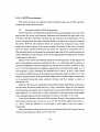
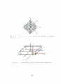
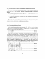
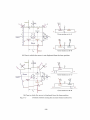
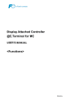
Figure 6.12・1 shows the analytica 1 mode1 for the driving forces. In this丘gure, the
mover and p olyphase armature conductors for the x−or y−directions only are shown. A
motmg 2・D且albach permanent・magnet array has the same structure as shown in Fig.
3.2.1・1,and fbur・pole・and・seven・segment magnetization with p ole・pitch length TpM=3
mm along the xi−andγ∫−clirections. Its dimensions are l l mm×11 mm×2mm, which
are ahnost two−fifths the size of the magnet−array dimension shown in Fig.3.2.1−1. The
ulthnate nmiaturization of the permanent・magnet mover enables higher accelerations
to be generated using the same armature currents and且ux density as given in
Subsection 3.3.1.
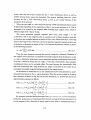
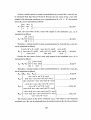
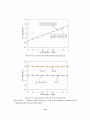
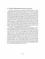
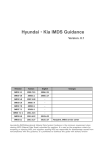
Figure 6.1.2・2 shows an analyticaUy obtained且ux・density disUibution on the plane
O.5 mm below the mover bottom for the x市and y.−directions. Figure 6.1.2−2 indicates
that the permanent・magnet mover a lso generates a quasi・sinusoida1且ux density with a
pitch length ofτ=2.1 mm in the xm− and ym−directions・On the other hand, pitch lengths
of the meander・shaped armature conductors are equa1 to the pitch r(=2.1 mm).
In the mover motions, there are 3−DOF rotations.且owever, this analysis deals with
the rotations around only one axis(xm, y励, or zm). The rotational angles around the x.一,
.Ym−, and zm−axes are referred to as roU an91e 7, pitch angle B, and yaw angleα,
respectively」
The driVi ng forces acting on the mover can be calcUlated from the Lorentz force law
with the same equations as Eqs.(3.3.1・1)一(3.3.1・8).
173
.十、
「一「
「.一
「
1
一
Armature conductors
1.・
forx−direCtional drive
1
川
㌦
E
1
1
∋鈎
i◇
〉,s・〈う
i
1
1
lli
1
a
II:V
『
x
’”
2τ
γ
3
2τ
丁
1
1 i
}2τ
1丁
1
1
τ.T
1
1
遅
i
1
1
L=1
(a)Supplyingもhree・phase currents f()r the x−directional drive.
Armature conductors
β
fory−direCtiona|driVe
@
ス 1_.r
O
〉・
ら.ら
“.
α
fi コ
÷』
菰 ら・
、σ
.÷
L⊥____τ
ら
今一輪「
γ=:□
ヴら ら.
匠三圭≡⇒…÷
1
一一2r }T,
匡三≡丁巳≡、
L
3
’i la
⊃
(b)SupPlying three・phase currents for the y一dlirectional drive.
Fig. 6.1.2・1; Analytical model for 6・DOF driving forces。
174
500
400
600
(
8
)
喝”
.≧
8
8
300
400
200
200.
0
i 1100
D” ’
.一’
T.
0
一200
,i一
一IOO
き
口
一400,
一200
一600、
傷・陥
.‘
S6
一300
一400
..・「 つ
.....・r・....
ち〃−4−6
Dつ〇一
一罐ぽ
Qヅ
一500
ツ
Fig.6.1.2・2:
Flux・density distribution on the plane O.5 mm below the
皿over
bottom.
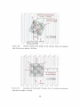
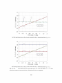
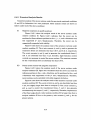
(D) Analysis results fbr 6・DOF driving fbrces:
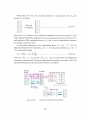
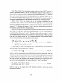
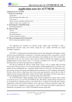
Figure 6.12・3 shows the anaユysis results of the driVing f()rces&, E., Tr, T,., T. f()r the
yaw angleαwhen the 4−and g−aXis currents for the x−directiona! drive are supplied(J、tr
=1A, orし=1A), the air gap between the mover bottom and ai’mature conductors is O,5
mm, and the pitch and roll positions are not displaced(β=y=Odeg). Figure 6.1.2・3
indicates that the d−axis current generates the translational f()rces F. and torques T.,
and the q−axis current generates the translational forces Ev and torques Tr, T,.. The
translational forces Er, F, and torques ny・ are a1皿ost constant, and the torques Tl. and T.
are proportional to the yaw angleαwhen the yaw angleαny O deg. Because of the
symmetric magnetization of the mover, the same driving forces can be generated every
180deg.
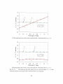
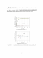
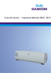
In the same way, the driving ferces resulting fi’om the d− and q−aXis currents for the
)一directional drive I、tv., Ig.i. can be numerically analyzed, and are shown in Fig.6.1.2・4.
From these results, the d−axis currents fbr the x−and〕・−directional drives i、lr and I,i、「
generate nearly equal translationa1丘)rces E. and torques r,, and therefbre cannot be
uniquely determined f壬om the total translational forces F. and torques T,. In other
175
w・・d・,with・nly th・d−aXi・ ・urr・nt・伽th・x−andγ一由recti・na邉v・・ldu and 1、,,
2’DOF妙ing飴rces cann・t be c・nt・・U・d. Th・t・rqu…e・ulting丘・m th・g一舳
・urr・nt・f・・th・x−and y−・lirecti・nal d亘ves伝and拓紺・・imila・ becau・e・f th。
symmetry of the actuator.
When the yaw angleα=±24.7 deg and±45 deg,3・DOF translational fbrces ca皿ot
b・g・n・・at・d rega・dless・f th・magnitudes・f・the・d−・and・9−aXt・・cur・en偽伝, lqx. Thi・i・
presumed to be caused by the magnetic field resUlting from magnet mover, which is
t且ted an angle of 24.7 deg or 45 deg.
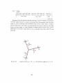
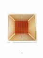
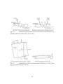
The mover generates opposite magnetic poles every pitch lengthτin the
.Mm−・lirecti・n・and・・th・magn・ti・p・le・at a p・・iti・n・and・5rdi・tant p・siti・n a1・ng th。
ルーdirection are mutuaUy opposite as shown in Fig.6.1.2・5. When tited byαb=23.6 deg
(・1・・et・24・7・deg)・in・th・a−directi・n, th・m・v・・g・nerates・PP・・it・magneti, p。1。、 every
2τalong the x∫−direction as shown in Fig.6.1.2・5 because of geometry relation, as shown
in the following equation:
α・=・in−1
k2τ5τ〕=23・6deg・・…….…….……..………………...………………..……..……(6.・.2−・)
Then, the same armature currents且ow every 2τ along the xs−direction. Therefbre, if
the magnet mover generates a completely・sinusoidal magnetic丘eld distribution in the
xm−and y.一一clirections, each phase current generates opposite translational fbrces every
2τ in the x.−direction du血g the yaw angleα=23.6 de g. Consequently, these opposite
translational fbrces can be mutually offset. The error between the theoretically(23.6
deg)and analyt元cally(24.7 deg)obtained yaw angle is presumed to be caused by an
incomplete sinusoidal magnetic field generated by the magnet mover.
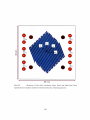
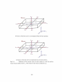
As mentioned in Subsection 3.2.1, the m血iaturized mover also generates a quasi・
sinusoida1且ux density in the xi−and yt−directions. When the mover is t江ted by 45 deg in
theα一(lirection as shown in Fig.6.1.2・6, the且ux densities Bx,∂ソ, Bごbelow the mover are
approxhnately expressed as fbUows:
輌・石)=−Bm(・・)・in〔。lti;−dx・〕…〔,:
l………一…・・………一…・……・(6…2・2)
・y・
輌・・』ω…〔π XlTPAd〕・i・〔 ,元ア1〕……………・……………・・…・………・・(6…2・3)
』・・Zs)=矯in〔π xlrPAイ〕・in〔。:, (6…2・4)
So, armature currents flowmg through a lineみ(i=xor y, k=u, v, or w)in armature
conductors, i」・k generate no translational fbrce l)ecause average of the且ux densities Bx,、Bv,
B。 with respect to the必一direction is nearly equal to zero, that is, translational fbrce F,
176
shown in Eq.(3.3.1・3), is expressed as fbUows:
/戸=・・/戸N・・S,,B・⑭.…………...………………....……….…(6.・2・5)
F=−
w怪・B)一…...………………..….……………..…………..…….……..(6.、.2−6)
Figures 6.1.2・3 and 6.1.2・4 a180 indicate that a magnitude of torque 7>resulting
丘om the mover tiled by 24.7 deg is larger than that by 45 deg. Magnitudes of torques]㌦
and Ty resulting from the mover tiled by 45 deg are equal because且ux density resulting
from the magnet mover is symmetrically disUibuted in the xs−and距directions. On the
other hand, magnitudes of torques Tx and Ty resUlting from the mover tiled by 24.7 de g
are not equal because of asymmetric dis旋ibution of the flux density in the x、−and
Ys−directions.
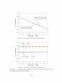
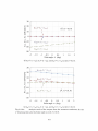
Figures 6.12・7 and 6.1.2・8 show the analysis results of the torques Tx,7}, T.. for the
pitch angleβwhen the o』and g−axis currents are supplied(伝=1A,」伝=1A,レ=1A,
or」lay=1A), the yaw and ro皿positions are not displaced(α=γ=Odeg). From these
results, it can be seen that the d・−axis currents generate the torques Ty proportional to
th・pit・h angl・βand th・g−axis c㎜・ntS 9・n・・ates th・瓠m・・t・・n・tant t・rques T,.
Figure 6.12・9 shows schematic views of the generation of the torques 7}. The g−axis
current for the y−directional drive also generates the tx)rques T. proportiona 1 to the pitch
angleμ
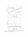
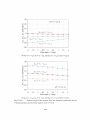
Figures 6.1.2−10 and 6.1.2・11 show the analysis results of the torques Tx, Ty, T. fbr
the roU angleγwhen the o』and g−aXis currenbS are supplied(伝=1A, Igx=1A, Idy=IA,
or lay=1A), the yaw and pitch positions are not displaced(α=β=Odeg). From these
results, it can be seen that the d・−axis currents generates the torques]㌦proportional to
the roU angle% and the g−axis currents generates the almost constant torques Tr.
Figure 6・1・2’12 shows schematic views of the generation of the torques Tx. The 4−axis
current fbr the x−directional drive also generates the torques T. proportional to the roU
angle r.
177
20
40
1(7’,),、・24.7[>1(γ二)rt..b−1
2
30
15
邑lo
207
憲5
ξ
2
口 0
lo
0
0
\」/.
亘
&i
ε一5
−io8
碧
宮
o
−20e
匡’iO
−15
1A・・
一30
一20
一40
一90 −60 −30 0 30 60 90
Yaw angleα(deg)
(a)Driving fbrces加m the 4−aXis current for the x−dii’ectional di’ive ld,=1A.
20
40
15
2
30
ε10
害5
で
2
日 0
20目
10る
}ひ
’7’
0 斥’
言
ご
一10㎏
呂
一20ぎ
.9 −5
烏
冨
=−10
E
、T.r
−15
一30
1( T.r)、,・4sl lCT,・),、−4sl
一20
一40
一90 −60 −30 0 30 60 90
Yaw angleα (deg)
(b)Driving forces from the q−axis current fbr the x−directional driveち、,=1A.
Fig.6.L2・3: Driving forces fbr yaw ang]eαat pitch and roll anglesβ=∼’=Odeg
when the armature currents fbr theエーdh℃ctional drive are supplied.
178
20
40
1(z1二)、,−24.・[>iσ),、..4il
2
15
30
207
邑lo
巨
§5
扁 0
lo 2
旦
/.’\
0 已
㌧∨
ぎ一5
一ユ障
亘
.20ξ
‖−lo
占
一15
一30
一20
−40
一90 −60 −30 0 30 60 90
Yaw angleα (deg)
(a)D亘ving fbrces丘om the∂−axis current for the y−directional drive ld),=1A,
20
40
「(Tx)。・45|k、Tv),、.451
15
30
乞
ε 10
に’
8
L
20巨
で
loる
5
?
0
o『
肩
o
=
.10肖
一5
’二:
6
芝
〔−10
L
α=24.7deg
一20き
9
一15
一30
一20
一40
一90 −60 −30 0 30 60 90
Yaw angleα(deg)
(b)Driving fbrces from the g−axis current fbr the J一directional drive 1亘、.ニ1A.
Fig.6、12・4: Driving fbrces fol’yaw angleαat pitch and roll angles fi =y=Odeg
when the armature current・s fc)r the .i,−directional drive are supplied.
179
一
「
一
「一「
.・
D1し.
’n
ソ、,,1
1
一1
「一
Mutual「y opPosite poles
for the)C〃−direction
Opρosite driving
ft)rces are offset
ll
の
SnS 1
1
i
li
句
↓≧ 1
σ、 の
1
L
A.
1
α
1
1
の
の
1
の
}1
1
2τ1
α=23.6deg
llll
,1 ,”
1
E
O
口§am竺三「「99/S一
[
..J
一
Fig.6.1.2・5: Relation between pitch lengths of the meander shape and magnetic
pole when the yaw angleα=23.6 deg.
1
il
一
1
x’
)㌔
Z
oo
の Z
の
Z
Z
の
Z
の
Z
の
Z
Z
の
@33.7τ
b1
1
乃
1.・・lt、・.・・1
F=一Σ∫,セ、・・8)・−ll・,≒o
ノ.k ”
i
の
∫.旭・.…∫ぴ・t?・・
iNo translational
if。・ceg・・e・ati・・
l
i
1
㌦
0
{,、・
Fig.6.1.2−6: Integration of且ux density B二along a line
when the yaw angleα=45 deg,
180
1)・kin armature conductors
15
10
言
日 5
z
邑
已 O
F・;””−5
Id.v
日
一10
・15
一2
一15
一1
一〇5 0 05
1
1.5
2
Pitch angleβ(deg)
(a)Driving forces due to the d−aXis current for the x−directional drive塩,=1A.
15
10
官
ξ
5
E
)
0
z
/
’− р氏f一合一一〔←・一.fi− ・一・s!一・−fF−_fi_.
t
巨’
一5
P
一10
一15
一2
一1.5
一1
一〇5 0 0.5
1
15
2
Pitch angleβ (deg)
(b)Driving forces due to the q−axi. s current for the x−directional driveんv=1A.
Fig.6.L2−7: Driving fbrces fbr pitch angleβat yaw and 1’oll angles cr=〆=Odeg
when the armature currents fbr the x−directional drive are supphed.
181
15
10
官
∈
z
T.v T.
,−
5
t
l
t
≡
)
φ
0
タ ー
in△一・−tS.
. 一合一 ・ −de ≡ −a合一 一 一
^・
口1
一5
fd)・=IA
Tv
A
一10
一15
.2
一1.5
一1
一〇.5
0
1
0.5
15
2
Pitch angleβ(deg)
(a)Driving forces due to the d−axis current for the )」−directional drive ld、,=1A.
15
7’
10
?D
官
巳 5
Z
.....
@ ...・.......
@ .
ε
自 0
@ τv .
.A
&”’
D5
己
ノ、、、・=1A
一..
.」.
@ 1’, 一
一10
@ ..・「「 .」
一15
@ ‘ ‘ .
一2
一15
一1
@ .
一〇.5 0 0.5
1
1.5
2
Pitch angleβ (deg)
(b)Driving forces due to the q−axis cui’rent for the〕r−directional drive∫1,t,.=1A.
Fig.6.1.2−8: Driving fbrces fbr pitch angleβat yaw and roll anglesα=γ=Odeg
when the armature currents for the s−directional drive are supplied.
182
Mover
、1’=.;’
0
Disp[aced inβ
T,,>0
CE)
AUraction force
d−axis current
for.Y−drive/、t,>0
・Y、
N S
S
N
Stator Positive lorqtle generation
(a)Generated torques T,,丘om the dLaxis current for the x−directional drive.
)・つ∫ M。verろ・<0
・瓢:;∵1驚:顯 。)
↓,tC .、
S N
S N
Stator Negative torque gelleration
(b)Generated torques Ti. f士om the q−axis current for the x−directional ditve.
)’=.1・、 Mover 71・>0
「
S
Stato「 Positive torqしle generation
(c)Generated torques T,.f士om the d−axis cun’ent f{)r the .v−directional drive.
Mover Zi・=O
.∼.’=.T’、
Disp「aced inβ
o〈/
: ‘/−axis current
fo「.1一drive/...、>0
『・
0(N◎Tnagnetization)
Stator No Tol’qLlc genen’atioll
(d)Generated torques T,、 fi’om the q−axis current for the .i’−directiona1 drive.
Fig.6.L2・9: Schematic views of generation of torques T,..
183
15
10
官
il 5
/.
z
邑
已 0
・1・.5
∫d.y
一10
一15
一15
一2
一1
1
一〇5 0 0.5
2
1.5
Roll angle/(deg)
(a)Driving forces due to the d−aXis cum’ent for the .r−directional drive塩v=1A.
15
10
...
.
......
..
官
巨 5
Z
..
D.
.
@ ・
.・
・
7∵
ε
已 O
.・
.
A
t’“・
D5
...
ご
∫甲=
・
1
...
τ二
一10
.・.
D
.
一15
.2
.1.5
一1
一〇.5 0 05
1
1.5
2
Roll angle 1(deg)
(b)DrMng fbrces due to the q−aXis current for the .r−directional drive lci.r=1A.
Fig.6.12・10: Driving fbrces fol’roll angle/at}・aw and pitch anglesα=β=Odeg
when the armature currents fbr the x−directional di’ive are supplied.
184
15
10
Tし. 71.
E
/ /
z日 5
ε
已 O
7−°
一
秩E・一;tw.】、.t..tr’記一・〔・・一.
.挙.
ィ一一{←・.一・Pt・C∴・Z=
ti−・
∫dv=IA.
Tx
一10
一15
1
一2
一15
一1
一〇.5 0 0.5
1
1.5
2
Roll angle/(deg)
(a)Driving forces due to the d−aXis current for the y−directional drive J,1、,=1A.
15
10
官
ξ 5
z
ε
自 O
\ 『→ …臼… ↑
r
に」5
・
一10
一15
一2
一1.5
一1
一〇5 0 05
1
1.5
2
Roll allgleγ(deg)
(b)Driving fbrces due to the q−axis current fbr the S−directional drive塩1.=1A,
Fig.6ユ2・11: Driving fbrces fbr roll angle! at yaw and pitch anglesα=β=Odeg
“’hen the armature cun’ents for the .i一dii’ectional drive are supplied、
185
・r=・N’、
Mover
7’、>0
Displaced in 7
イ!−axis cur「ent
夢ぷe∫〉°
Stator Positive torque gelleratioll
(a)Generated torques Tr due to the d−aXis current for the x−dii’eetional drive.
.・’・= .X、 Mover 71, =O
O S
DiSPIaced inγ
〔 t∫−aXIS current
㊤,
for.v−drive t >0 1・
「’‘・ ・㌧
「
0(No magnetization)
Stator No↑orque generation
(b)Generated torques T, due to the q−axis current for the x−directional drive.
T>0
’1’;A’、 Mover
Stator Positive torqしle generation
(c)Generated torques Z, due to the d・−axis current fbr the v−directional drive.
.N’=x、 Mover τ>0
Stator Po9. ilive torque generaUol1
(d)Generated torques Tv due to the q−axis current for the〕・−directional drive.
Fig.6.1.2・12: Scllematic Ntie“’s of generation of torques 7r..
186
As the analysis results above show, the driving fbrcesノ『t, F,., F., Tr, T,.,乙can be
expressed丘o皿the d−and q−axis currentsん.,ん,1,t)、,ソ, as fbllows:
ε,
F:
ノ‘tr
KI.−F(d,β,γ)
l、ir
......,.’.....㊨............,......................,......,.”.......(6.1.2−7)
6×4皿atri
z、・
1‘{ト・
Ig),
T,
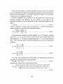
where Kl.・1・is a 6 x 4 matrix and all elements of the matrix nonhnearly depend on the
yaw angleα, pitch angleβ and roll angle/In this study, the pitch and roll
displacements of the mover are assumed to be very sma11(β定Odeg and 7=Odeg)
because of small air gap(less than l mm)between the mover and stator, and in the
range, all elements of Ki.i・ almost linearly depend on the pitch and roll displacements.
Further皿ore, if the yaw displaeements are assu皿ed also to be very srnall(αzO deg), all
elements of Ki.v・almost linearly depend on the yaw displacements, and the system・
constant matrix Ki・・7・is expressed apProximately as follows:
κノィ.
E、・
0
迭
0
O
Ki.〔.
O
1‘tr
l,1x
______...______.__.(6.1.2−8)
K’ il, fl
KIr・
Jd,,
ll、・
−Kl《・
K〃・cr
J,t,・
z.
κ〃17
κ〃,β
7i,.
whereκ,ぞ,κ1c, and Kyアare constant(in this analysis, fbr a O,5・mm ahr gap, Ki,c・零17mN,
κア1’ ・12mN・mm, and Kl7, =4.5 mN・mm). Equation(6.1.2−8)indicates that the driving
f()rces due to the d−axis currents Jd, and泓、. are equal because of the symmetry of the
actuator. Therefbre, even迂the two currents Idv andん,. are controlled, only 1・DOF
driving fbrces can be controUed in the range withinαre O deg,β≒Odeg、 andγたOdeg.
Therefbre, controUing the fbur arnlature currents in the吻一f已ame controls the 3・DOF
motions of the mover(fbr instance, x−, y−andご一皿otions, or x−,」一, andα一motions). In
order to realize both 3・DOF motion controls on a plane and magnetic suspension, the
planar actuator needs to be redesigned.
187
6.1.3.Conceptual De8ign of Fundamental St】ra(加re
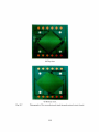
In order to suspend the mover, su8pension fbrces that balance the fbrce of gravity
need to be generated. E quation(6.1.2・3)indicate8 that negative d−aXis currents(ldu,侮<
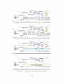
0)generate suspension fbrces(尾>0). Figure 6.1.3・1shows schematic views of when the
d−axts currents are supplied. Negative d−aXis curTents to actively contro1 leVitation
fbrces(Fz>0)always generate re8to血g torques against theβ一and r− displacements.
The restoring torque8 stabilize theβ一and r−motions of the mover.
Equation (6.1.2・3)also shows that the g−axis currents Igx, Iay generate the
translational fbrces Fx,ちon a plane without vertical fbrces」Fz. Therefbre, the d−and g−
a)dS C㎜ents伝, lg。, ldy, lgy:
> independently control the translationa1]1orces Fx,ち, Fz
> stabiUze the pitch and roU motions.
且owever, the d‘−axis currents utiized to control the suspension fbrces」巳, generate
yaw−directional torques proportional to the yaw angleα, that is, they generate instable
yaw motions. Therefbre, in order to realize both 3・DOF motion controls on a plane and
magnetic suspension, a stabilization mechanism for the yaw motions is needed.
Then, we can consider the fbUow血g two methods toward addition of the
stal)ilization mechanism;redesign of structures of the permanent・magnet mover or
stationary armature conductors. Fab亘cating the permanent・magnet mover is d避icult
in bonding each permanent・magnet component. On the other hand, the armature
conductors can be且exibly and easily manu£actured by means of mult且ayered printed
ch℃uits. In this study, the armature conductors are redesigned to offer stable yaw
motion with less interference to the translationa1, pitch, and roll motions.
The torques acting on the mover depend on the relative yaw, pitch, and roU
distances between the mover and the armature conductors, but relative pitch and roll
distances should be a lways nearly equa1 to O deg in order to maintain a sma皿air gap.
The torques also depend on pitch lengths of the armature conductOrs, which determine
an alowable max血um width of those as shown in Fig.6.1.3・2. The width of the
armature conductors also determines an aUowable maximum current of those, and so
design of the armature conductors includmg Pitch lengths as a parameter tends to
become comphcate.
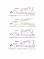
In this study, new armature conductors with different relative distances in the yaw
direction丘om the armature conductors fbr the x−and.y−(lirectional drives are
introduced to control the yaw motion as shown in Fig.6.1.3−3.
188
含・・V…一・
NSNSNSN
Mover
Mtlll
NsNsNsNsNsN Stator
Negative d−axis Current(/dく0)
(a)Generation of the levitation fbrces F..
竺Ω血gforqαe
Mover
(displaced inβor/)
NsNsNsNsNsN Stator
Negative d−axis Current(ld<0)
(b)Generation of the restoring torques万, and Tr.
Propulsion force
M°ve「
Stator sNsNsNsNsN
q−axis Current Iq
(c)Generation of the propulsion forces Er. and F,..
Fig.6.1.3・1:
Conceptual design of a magnetically leVitated planar actuator,
189
」 一 ... ..
Fig.6.1.3・2: Allowable maximum width of the armature conductors determined by
pitch length of those.
‘Tilt
r””NL...7
,’/
、、
Fig.6.1.3・3:
New introduced armature eonductors tilted in the yaw dii’ection.
190
Figures 6.1.2・3 and 6.1.2・4 mdicate8 that the d−−axis current generates translational
fbrces Fz and torques Tz, and the 4−axis current generates translational fbrcesノ㌦, Fy and
torques Tx,7}when the pitch and roU position8 are not displaced(β=γ=Odeg). So, at
least fbur kinds of the g−axi8 currents, that is, fbur pah!s of polyphase currents are
needed to actively contro16・DOF motions.
Furthermore, Figs.6.1.2・3 and 6.1.2・4 indicate that the d−and g−a】ds currents
gellerate o】〔且y torques without tran81ational fbrces when the relative yaw distance is
24・7deg or 45 deg・As mentioned in Subsection 6.1.2, a magnitude of torque 7三resulting
from the mover tiled by 24.7 deg i81arger than, that by 45 deg. Therefore in this study,
the armature conductors are tilted by 24.7 deg tn the yaw direction丘om the armature
conductors for the x−directional drive, I term this arrangement ”armature conductors
fbr theα一directional drive.”When the yaw angle of the moverα=Odeg, the d−aXis
currents fbr theα一directional drive Ida:
> generate only torques T,
> without vertical fbrces凡.
Therefbre, the d−−axis currents Idα can separate the generation of the vertical fbrces
尺and torques Tz, and stabiize the yaw motion. To date, the 4−and q−−axis currents are
generated by three・phase currents, but they can be also be generated by two・phase
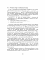
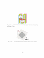
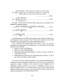
currents. In this study, a magneticaUy levitated planar actuator with three pairs of
two・phase armature conductOrs is organized as shown in Fig.6.1.3・4. Tables 6.1.3・1and
6.1.3・2show the specifications of the m血iaturized permanent・magnet mover and a
triple・layered printed circUit board mo皿t血g armature conductors, respectively.
191
y Top view
tt グ ’ パ.,、.后〆〃:万 ./’ s,.
β
i.…川・.・.、.1.・・2〃拶
憂§難lll繧
z x
α γ
’
Mover
(1{albach arra)..)
賎
, ら .・ら ら ら
辮1彗R。∋。や
StatOr
e日:{8}
ぐ■ 1.● ,$ 鵬1’
(3−la)’erprinted circuit)
医.コ1. 、、
ロカ s
h
ド ごロ
ノ1鍵:1
Two conductors
アf。,)・.d,ive
T、vo conductors
1 fbr x−drive
二し :.、÷:∼..
鞍壷鍵._.一
’、・∼.∼ ’
Two conductors
i fbr a−drive
‘みasis
li .1
.
Mover
er
τ/2
S−ax】s
膓 1/
ノ∫
tt
StatOr
@∫
”
Thickness:0.lmm
Side view
z
α
ア
Insulating layer(Thickness:0.2 mm)!
(a)Fundamental structure.
(b)]N{anufactured stator and mover.
Fig.6.1.3・4: Magnetically levitated planar actuator.
192
Table 6.1.3・1:
Specifications of miniaturized permanent・magnet mover.
Mate亘al
NdFeB(Shin・Etsu Chemical Co., Ltd.)
Residua1且ux density Br
1.35−1.41T
Overall dimension
ll mm×11 mm×2mm
PM component
2mm×2mm×2mm, or 2 mm×1mm×2mm
Tota1 mass
1.89
Table 6.1.3・2:
Speci丘cations of triple・layered printed ch℃uit board.
Number of conductor layers
3
PitCh of meander pattern,τ
2.1mm
Number of turns of meander pattern
16
Width of conductors
0.8mm
Thickness of conductors
30 一 35 pm
Thickness of insulating layer
O.1,0rO2mm
Resistance of each conductor
1.0Ω
193
6.2.Dynamic BehaVior of Mover
The mover has 3・DOF translational and rotational motions because there is no
mechanical suspension mechanism. When the physical quantities of the mover motion
are repre8ented, it is extremely important what coordinates are respected. The
translational motions are often represented w誌h respec乞to乞he stationary coordinate,
and the rotational motion8 are often represented w比h respec乞to the mover coor《㎞ate.
This section introduces an equation fbr the 6−DO亙]【notions ef the mover that desc亘bes
the dynamic behaVior. ・
6.2.1.Mass and lnertia Tensor
The mass M and inertia tensor J.’ef the m《rver are determined by mass・de】窪sity a丑{垂
dimensions. The mass M was measured us垣g an eleetronic sca le(LIBROR, EB・・320鐙,.
Shimadzu Corp.)that has a O.1−g resolutio江.「駈e scale垣《五ca給《l that. mass・擁:=・1.8:gi.
which agreed with the theore昼cal value calcUlatedi丘o]【n mass de丑s迦ρ=7↓6③×103三
kg!m3 and volumeγ=224 mm3. The hle垣a teDsorみ.’Wtt}1 respecも:挺樋e・mover
coor(linate axes xh、ym.7m with an頭9in at O’, correspen砲g to the ce疏e宝・of;搬ss・o£;』・・
mover shown in Fig.6.2.1−1, can be represe亘ted as a 3 x 3 mat亘x a…s島避Ows・;
J.‘」㌶J.
Jm’=J♪。’」ガJ♪.
................_...右.Q.輪...⑰.飢_◆..。...。.繊◆_.....◆..........}見.軌.}}}__..〈6こ2二玉ヨi)
J.’」4J=
where the diagona1 elements 」. ’,み’, aロ、d X』’』are the. m.o敬e,n.ts・o銑he・返le頭al abou±磁e.
xm−,ルー, and z〃7−axes passing throuきh the cen搬・o£磁ass of血e血◎ve鵬主espect担e雄;. a盈《美
the o任《五agonal elements・ん’,」)実’,4零’,み’;ム.㌧銀dふ♪a苦e竈e騨od迫cts of the血e斑a・
These elements can be de丘鵬d as the章遊o“厄.殴琴e寧惑ion;:
」〆=1ρ硯2δバr)・rk)ばγ...___一一___._。。。_繊漣
whereρis mass densi観P=[司 聾 縫τIs a…袈s垣Q穎,、 vecto壬曇壁旦.疋磯a越顛.¢鰻鎗奪w姪鮭
・espect t・the m・ver℃oo叉・撫蜘㈱s獅癒弓麺鴫;.左・=・1,,2違殴磁.煕磁s磯』・
Position vector r, and 4R is KTQ駐e¢ke置《1¢1ちa・無垣e琴毒.i塾亀en§o書痴.邑o£ぴ璽eetaD・膠a鍵頚越:§m5.
which has u頑。顛ma領撫siも顯、嘘垣e綱磯垣壌・¢Ω壁撫撫撫題藤,頑轟、癒・
origin at O cξEロbeξepξese旦垣《董as・趨且◎ΨS;
襲挺
吉〃‘。2+1。2)・ ・
@・ 誕2+1.2)・
」・L
o o ⊥M
............._....._.._......(6.2.1・3)
(1.2+1.・)
12
where lx, ly, and lz are the len
gths of the edges of the prism as shown in Fig.6.2.1・2. Next,
/of the same prism with respect to the
we can easily calculate the inertia tensor Jo
coordinate axes x“p7, with the origin at O, pata皿e1 tO the coordinate x.Or.z. with each other
as fbnOWS:
b2+c2
Jo, ’=Jo’+M
−ba
−ca
一ab −ac
c2+a2 _bc
◆...__.._.............◆....◆......................(6.2.1−4)
−一・cb a2+b2
c]ア◆
where dt=[a b ls the displacement vector from the origin O to the origin O,. The
inertia tensor Jm’of the mover with respect to the coordinate axes x3iv。tt、 Js’can be
calculated丘om Eqs.(6.2.1・3)and(6.2.1・4)as fb皿ows:
0.1828 0 0
Jst=
・10−7kg・m・.___◆_._.____._____.(62.1−5)
0 0.1828 0
0 0 0.3543
As we can see, the inertia tensor/1’is a diagonal matrix. The diagonal elements of
the inertia tensor/1’and the coordinate axes U、z. are referred to the princip a1 moments
of mertia and the principal axes, respectively. Once the principal moments and their
axes of the mover are known, the inertia tensor Jm, with respect to any other axes
passing through the center of mass, can be fbund by a shnnarity transfbrmation de丘ned
by the Euler angles relating the two coordmates. If the transfbrmation matrix is given
as R, the inertia tensor Jm’can be represented as fbUows:
Jm’=RJ5’R7...◆....◆..._.....◆..........◆............◆........................_....._...................(6.2.1・6)
The transformation matrix R from the stationary・coordinate axes石γ冨, to the mover・
coordinate axes xh,yh,z. shown in Fig.6.2.1−1is given as fblows:
cos(π/4) −sin(π/4) O
R=・in(π/4)…(π/4)0
...◆...........................◆...................._....◆.............(6.2.1−7)
0 0
Therefore, we can ca lcUlate the inertia tensor Jm ’ of the mover with respect to the
mover・coordmate axes x∂,㎡m as fb皿ows:
0.1828 0 0
Jm’=
0 0.1828 0
・10−7kg・m・._.__.____.__...____(6.2.1−8)
0 0 0.3543
195
㍗1η
〃1
Fig,6.2.1・1:
Mover with mover・coordinate axes x“∂・“ご“, and stationary℃oordinate
axeS芯):、ご.v・
)’t
・rf
Fig.6.2.1−2:
Rectangular prism with two mutuaUy−parallel coordinate axes.
196
62.2.EUIer Angle and Arigular Velocity
In order to define the 3・DOF rotational orientation of the mover, the Euler angle
needs to be de丘ned[GolO1, TajO6]. In this study, Euler angleφ=[α β /71 is de丘ned
丘℃mα,βandγas orderly counterclockwise rotations around the stationary二,一,)・.s−and
ぷ一axes passing through the center of mass of the mover, respectively, as shown in Fig.
6.2.2・1.At f丘st, an immediate coordinate xlγ}zl is defined to be rotated f士om the
stationary coordinate U宕, byαaround the二、−axis. Then, an皿mediate coordinate xぴz二2
is defined to be rotated丘om the coordinate x1γ向byβaround the y.−axis. Finally, the
mover coordinate x“」,“浮,,、 is defined to be rotated丘om the coordinate x2yユニ2 byγaround
the.v.,.−axis.
Next, the orientation of the mover coordinate x“D,,,ξ“, with respect to the stationary
coordinate x.O’・、z,, R。“、, is introduced宜om the Euler angleφWhen a body is rotated
counterclockwise by Vi areund an arbitraエy vectorλ=[λ1 λ2 ゐ]㌧the rotation matrix
Rv, can be represented as follows:
R,、ニE…9‘t・(?・IMI+7L,〃,+占〃、)輌・・a・11』(1−…V)__.…__….___(6.2.2−1)
where E is a 3×3 unit matrix and Mt(∫=1,20r 3)is an infinitesimal rotation generator,
which can be represented by the following equations:
0
ui:
0
E・
0
βfl=
0
....,..’..,_......._...._...__、..,...,.............㊨....._..................㊨㊨......㊨(6.2.2・2)
llii]…・闇一・一・・一・6…2−・・
0 0
0 −l
0
, 〃勺=
l O
Zl
z∫
α
zづ
・⇒
c−・i’.[〉
Ys
β
Xs
zηf
γ
Xnl
X]
Stationary coordinate
Fig.6.22−1:
)/1il
・x’.s’
Definition of Euler angleφ=[α
197
Mover coordinate
β〕]v’.
At丘rst, a rotation matrix’ to rotate counterclockwise by a aro皿d the z.−axis, R。1 can
be calculated from Eq8.(6.2.2’1)一(6.2.2−3). Because the unit vector of the zs−axis with
respect t《)the 8tationary coordinate x跳zぷis represented as 11ぶ=[0 0 1]「, the rotation
matriX R∫i can be represented as follows:
R・1=
Then, the unit vector of the ys−aXis with respect to the coordinate xOγlzl,彪is
represented as follows:
0
4sニR。1−1
Slnα
COSα
0
_........................◆..............◆....◆..................._............(6◆2.2−5)
0
Therefore, a rotation matrix tO rotate counterclockwise by fi around the ys−axis, R 12
can be calcUlated as follows:
R12=
cosβ+sin 2α・(1−cosβ)
c・sα・sinα・(1−c・sβ)
…α・・inα・(1−・・sβ)
…β+…2α・(1−…β)
一sinα・s口1β __(6.2.2・6)
sin a ・ sin 6
COS fi
−COSα・sinβ
COSα・sinβ
Fina皿y, the unit vector of the xs−axis with respect to th is
represented as follows:
COSα・COSβ
λms=Rl 2−I Rs1−10=−sinα・cosβ ___..___.__._.._____._.___(6.2.2・7)
O sinβ
Therefore, a rotation matrix to rotate co皿terclockwise by r aro皿d theひaxis, R2nt
can be calculated as fbUows:
R、m= [R、mlR、m、R、m、]...__.__.__.__..____.____.__..____.(6.2.2・8)
…r+…2α・C・S2β・(i−…r)
R2ml=
・inβ・・in・1−…α・・inα…S2β・(1− COS 7)
.............._._....◆◆.......(6.22・9)
・inα・C・・β・・in・1+…α・…β・・iψ(1−・・Sγ)
一・inβ・・in・7−…α・・inα・c・・’β・(1−…γ)
R2m2=
…r+・in2α…S2β・(1−COS 7)
__.._....._............(6.2.2−10)
…α・…fi…i・r−・inα・c・・,B・・inβ・(1−…γ)
一・inα・…β・・inγ+…α・…β・・inβ・(1−COS 1)
R2m3=
一、。、α・C・・,B・・in・r・一一・inα・…β・・inβ・(1−…γ)
....._._.............._(6.2.2・11)
…γ+・in2β・(1−…r)
The rotation matrix of the mover coordinate x例ymz功with respect to the stationary
coordinate xW。, R。m, can be calcUlated from the rotation matrices Rsi, R i 2, R2m as follows:
198
R、m = Rs’IRI2R2m
COSα・COSβ 一Sinα・COSβ Sinβ
=Sinα・COsγ+cOSα・Sinβ・Sin l COSα・cosγ一Sinα・sinβ・s㎞γ 一cosβ・Sinγ
Sinα・Sinγ一COSα・Sinβ・CoSγcOSα・Sinγ+Sinα・Sinβ・cOSγCOSβ・COSγ
............_......._.....__(6.22・12)
The rotation matrix of the stationary coordinate xSy、zs with respect to the mover
coord丘1ate )chJlh,zm, R“,s, can be calculated as fbUows:
R朋。=R。m−1=R.m「
COSα・COSβSinα・COSγ+COSα・Sinβ・SinγSinα・Sinγ一COSα・Sinβ・COSγ
=−Sinα・cOSβcOSα・COSγ一Sinα・Sinβ・SinγCOSα・Sinγ+sinα・Sinβ・COSγ
Sinβ 一COSβ・Sin 1 COSβ・cOSγ
◆...◆._.....◆◆..◆◆.....◆.......◆..(6.2.2・13)
We can convert positions with respect to the mover coordinate x〃品into those with
respect to the stationary coordinate x躍, as fbUows丘om Eq.(6.2.2−13).
The angular velocity of the mover with respect to the mover coordinate x〃㎡加, as
shown in Fig.6.2.2・2, cz)sm ’=[∂,’toy’tDz’]τcan. be calculated as fblows:
ω、m』R、m’IR12−1ω。1’+R、m−1ω12’+ω、m’
=Rωφω誓 ’’’”°’’’’’’’’’’’’’’’’’’’’’’’’’’’’’’’’’’’’’”°’’”◆”◆◆’◆◆°°(』
Sin a・Sinγ一COSα・Sin fi・COSγ S桓α・cOsγ+COSα・S㎞β・Sinγ COSα・cOSβ
Rωφ=cOSα・Sinγ+S㎞α・Sinβ・COSγ coSα・COSγ一S01α・S㎞β・S㎞γ 一Sinα・COSβ
COSβ・COSγ 一COSβ・Sinγ Sinβ
......_.◆◆_◆◆..............◆◆◆.◆(6.2.2−15)
where∂,1’,ω12’, andσ㌦’are angular velocities of the mover about the z。−axis with
respect to the immediate coordinate xlylzl, the ys−axis with respect to the immediate
coordinate x2y2乏, and the xs−axis with respect to the mover coor{五nate㌔y房m,
respectively. The angular velocities tv。i ’,ω12’, and∂2m’can be calculated from the unit
vectors Zl、,ん,ん、 a nd EUIer angleφ=[α β IT as follows:
ω、ll=み。芸・ω121=ろ、誓・ω・加・=・1,m・書一・………・…………・……・・……・・…(6・2・2−・6)
Then, we can calcUlate the differential of the EUIer angle(4/dt)丘om E qs.(6.2.2・14)
and(6.2.2・15)as fbUows:
誓=R。φ⑧一1ω一1…・…・…・・……………・………・・………・…………・・……・………………(6・2・2−・7)
199
1
一l
Rdi,.
c・・(2α)
ラ コ
Slnα・Smγ一COSα・Sinβ・COSr
cosα’Smγ+sinα・sinβ・cosγ
x Slnα・cosγ+cosα・Smβ・sinγ
COSβ・COSγ
COSα・COSβ
シ
COSα’COSγ一sinα・sinfi・sinγ
一COSβ・sinγ
一Smα・COSβ
sinβ
.__._._._,,_.___..(6.2.2−18)
Equation(62.2・18)in〔licates thatthe matrix 1∼、41 cannot be defined, and therefbre
the Euler angleφcannot be uniquely determined丘om this equation when the Euler
・ng1・α=±45,・r±135 d・g・Th…ti・nt・ti・n・f th・m・ver i・・ft・n・al1・d…i・gUl。。
posture.”However, in this study, it is assumed tha七the mover is driven in the range
within the Euler angleα≒Odeg. Therefbre, a singular posture cannot occur, and the
differential of the Euler angle(dφ/dt)can be calculated fi・oM Eqs.(6.22・17)alld
(6.2.2−18).
z,η
A:.
(」)α
Ym
Xm
Fig.6.2.2・2:
Angular velocity di,。、’=[co.r ひ、、 tv,]Tand Euユer angleφ=[α β 7〕 T.
200
6.2.3.Equation of Motion
The equation of the motion of the mover can be represented by the translational
fbrces acting on the mover F、m=1万 ち 」Fz]「and tOrques around the mover center O・
Ts加’=[Tx’万刎「a8制・WS・
dり
”元加=塩+Fg……・・…・……・…・……・…・・…一…………・・……………・…・…….…….(6.2.3・1)
み,14 R加’=T。m・−tD。m・・(」.’・p。胡う……………….…….…….……...……………….……(6.蹄2)
where巳坊輌v, vz】Tand Fg=[00−Mg]Tar・v,1。city。fth。 m。ver and th。 f。,ce。f
gravity acting on the mover, respectively」
Equations(6.2.3・1)and(6.2.3・2)represent 3・DOF translational and rotational
motion equations of the mover, respectively. Al variables in the translational and
rotational motion equations are represented with respect to the stationary coordinate
xSy,z。 and mover coordinate xhJl..7励respectively. The position r,m and EUIer angleφof the
mover can be represented by the velocity vs〃2 and angular velocity m,〃!, respective1)ちas
fbUOWS:
dr。m
=ッsm_.____...______..__.__...◆...............................◆◆.....◆.......◆.(6.2.3−3)
fl=Rωφ⑯一1ω、m・・………………………・……………・…・.….………….….…….…………(6.2.3・4)
Equations(6.2.3・1)一(6.2.3・4)can represent dynamic behaviors of the mover with 6
DOF.
201
6.3. Planar Motion Control with Stable Magnetic Levitation
This section di8cu8ses 8ix・current controls to stably leVitate the mover and actively
control the xrナ, z−, andα一motions. There are two important things fbr the motion
controls:
〉
to generate independent translational forces」Fx, Fy, and F. with stable torques in
theγ一andβ一directions.
〉
to generate torques in the a−direction with less interference to translational
fbrces Fx,1『}, and Fz.
This section丘rst presents driving fbrces resulting丘om three pairs of two・phase
armature current8, and then the driVing force℃ontrol system.
6.3.1.1}ran 81ational Motion Control
In this study, three pairs of two・phase c㎜ents杉=1ん 勾79=x,ア, orα), as shown
in Fig.6.3.1・1, are assumed to be supplied to the three pairs of two・phase armature
conductors as shown jn the fbUowmg equations:
・1ノー一・ノ…ψv)….….………………...…….….……….………….……..…………….…....(6.3.1・1)
・、ノ=・ノ・inψv)…..….…………….….._…………….….…….………._………….….…(6.3.1−2)
Figure 6.3.1・2 shows phasor diagrams fbr the relation between the dq−frame and
α’
タ’一丘ame. The currents lix and lly generate the opposite・phase magnetic丘eld to that
resUlting from the permanent・magnet mover when the mover position in the x−and
.y−directions(x,.y)=(xs, Ys)and the Euler angleφ=(0,0,0). Theα’−axis are a五gned to the
oPPosite side of the current 1りaxis, and theβ’−axis leads theα’−axis by 90 deg. The
current llαgenerates a magnetic field that is tilted byψ=−24.7 deg around theα一
direction丘om that caused by current lix. Bearing this in mind, the armature currents in
the∂dq−frame々・and loj・can be represented by the currenbS lif and 12j as follows:
[1:]=[:翻
譲㌻6][;1:]………◆…・………・……・……・……・……・・……(6・3・・−3)
[il:]=[:馴
鵡㌻劉囲………・……………・…・・………・……・…・……・(6・3・・−4)
[ill]{:翻
識劉6:]一…・…・……・…………・・……・………・……(6・3・・−5)
αs=xs cosψ_ys sin q..____..,.__.____..____..__..______..._(6.3.1−6)
202
fi =axi g.
▲|brx−drive
d−axis
. . 1 . . . .
tbr a−drive
ll。,謂:v,▲1 ;r㌃芸i,c 442∴二;ivc
lI ” ノ
(y−axlS
tbr a−dri、ノL’
fi=axis
ギ
lbr 1,−drive
ヒ_レα’−asis
ib「ipdri、’e
・t
‘ 1..1 1 1 1 1 ‖刀
#・#・iH:i鵬オ]・1
氈E−ax】s
一 ゜1・P
・ 一 . 一
2τ1,.11.it・.ハ1・a4・.s
・一・
・> ibrJ一drive
d−−asis
!..F
{br、一drive
’ ノ./
ん㌧.,
〈・.:・忠,2・,
.〆:え
アβ
貰墜懇
.1 ノ.”...’
王ド
xα
tt
1‖
x
11
α
Gt 一㌘←ヨ←
γ
s’ つ 「)
Fig.6.3.1・1:
dg−frame and a’fiLframe for the x−一, y−, alldα一directional {irives.
与
β’−axis
fbrノーdrive
∫、・∫、Z・ゲ
.
び=エ.y. orα)
S−ax1S
う
品rゾーdrive
Magneticneld
’
f@’
、
due to mover
、、 、
膓,
@ ‘トaxis n)rノーdrive
\泓
免
π 1
丁ノ・
1bl’∫−d1
β,
Fig.6.3.1−2:
、
ソ 一ax
Jl/
Phasor diagram showing relation between dq−frame andα’βL☆ame.
203
These pairs of d・−and・−axis currents generate the translational fbrcesノ『、“, and
torques TvnJ’as fbllowsl
E
∫‘tr
E
F:
∫,lx
κ(r、・,tt ) ip)
∫d).
..,..................,...,.....”........,㊨㊨....㊨㊨.....㊨㊨....㊨...”(6.3.1−7)
71,’
6×6 rnatrix
1ぴ
Idα
T、・
T,1
ttα
where K is a 6 x 6 matrix, and all elements of K depend on the mover position,w、 and
Euler angleφWhere Euler angleφ=0, K can be approximated as shown in Fig.6.3.1−3,
and therefore 3−DOF translational forces万, F,., and F, can be independently controlled
by two・phase currents i. and i」..
In this study」references of the translational fbrces E,nt’= [4.’ F、.’ 1『』’]’1 are
deterロ1ined丘om the mover positions,、,,、=Lx’y :・]T and position references rsm’=[x’」’
z’
nフ’by three PID controls.
F、’.’・砿一r,n,)一・’芸・………………’一…・…………・…………・…・…・…………(・・…一・)
where Pl.・=[Pノ.1・Pl.・yノ)ノ.L一]and D∫,ニ[Di−:, Dハ. Di.L.]are proportional and differentia1
ホ コ
parameters, respectively. ln this study, refbrences of the armature currentsみand it. are
ロ
calculated丘o皿those of the translationa1 forces E,.“, as fbUows:
Drivjng
forces
4・
乙
Cur「ents
Translational force control
0 0000
000 00
0 0 00
Tx「
「)・’
3x4 3 x 2
∫dU
Idl・
14y
人31.人「ささくo
(fa
κ(へ。.φ)
[
㌫,]一[笥[;:1:]
ldα
matrix mat「ix
T:1
[〉[;・]・[剖[;:d
/q.v
(∫、凶,<o→1・:・ω
亀,。,quec。,,.,
6 × 6 matrix
∫、tv
匡i]一開[;:1::畷
cl・v
∫tiT.
tt:’
Fig.6.3.1・3:
Control method for driving forces.
204
闇=[Kn K12K31 K32]]蠕;2]・………………………………一……・……・…・………・・…(6・3…9)
[1::]{雛:]’i「乏12]・………一・…………・・……一一………………………(一)
Supplying the armature currentsみandんequal to the refbrencesピand↓’generates
the translational fbrces Fsm equal to the refbrences 1㌃胡゜.
6.3.2.Torque Chatracteristics and Rotational Motion Control
The armature currents i. and iy generate not only the translational fbrces Fsm, but
also the torques T。m’. Therefbre, it is extremely important to investigate how the torques
T。m’resUlting from the armature currents ix and iy in且uence the rotational motions of
the mover. When the Euler angleφ霜0, the torques 7…’, Ty’, and 7二’are do血nant on the
Euler angleα,βand 7, respectively. Next I perfbrmed a numerical analysis of the
torque characteristics due to the armature currents fbr the x−directional drive when
rotational motions with more than 2 DOF occur in the range within−2 deg<α,βandγ
<2deg.
Figure 6.3.2・1 shows the system constants K61(=7三’/、ldu)and」K62(=7∵/Iqx), which
are dominant on the a−motion, for the Euler angleα. The system constant K61 is
independent on the Euler anglesβand%and the system constantκ62 is almost
independent on the Euler anglesαandμFigure 6.3.2・2 shows the system constants Ks i
(=Ty’/ ldU)andκ52(=7ジ/Igx), which are dominant on theβ一motion, f()r the Euler angleβ
The system constant Ks i is hldependent on the Euler angle%and the differential(∂Ks l/
∂βis independent on the Euler anglesαand 7. The system constant Ks2 is almost
independent on the Euler anglesα,」6, and Z Figure 6.3.2・3 shows the system constants
K41(=T}’/ldU)and陥2(=Tx’/Igx), which are dominant on theγ一motion, fbr the Euler
angle 1. The system constantκ41 is independent on the Euler anglesαandβand the
system constant K42 is almost independent on the Euler anglesβand万
205
15
10
⊇
5
盲
ξ
z
0
日
)
5
一5
(β,7) (0,2),(2,2)
一10
一15
一2
一15 −1 −0.5 0 05 1 1.5
2
Euler angleα(deg)
(a)K61 (=r.J/娠)at(βr)=(0,0),(2,0),(O,2), and(2,2).
15
(0,2) (2,2)
10
?
㌫_一一k.__._
5
)
芦
ZT
0
∈
)
s
一5
(β、1) (0,0)
(2, O)
一10
一15
一2−1.5−1−0500.51152
Euler angleα(deg)
(b)K62(=T.ソlvx)at(βr)=(0,0),(2,0),(0,2), and(2,2),
Fig.6.3.2−1: Analysis result of torque万’due to the armature currents fbr the
x−directional drive fbr the Euler angleα.
206
15
10
(2,0),(2,2)
⊇
5
)
巨
子
5
0
7,
一5
(α,7) (0,0),(0,2)
一10
一15
一2 −15 −1 −05 0 05 1 15
2
Euler angleβ(deg)
(a)κ5i(=ny:11dr)at(α,カ=(O,0),(2,0),(O,2), and(2,2).
15
10
A
<
\
5
(O,O)
F
z
写
E
)
0
(2,2)
(α,/)=(2,0)
(O,2)
1
誤
・L.
t
一5
t
1
1
一10
t ’ ”
, ● ■ . 一 ・ 桓
一 ・ ・ ρ
・ ● 、
一15
一2 −L5 −1 −05 0 05 1 15 2
Euler aiigleβ(deg)
(b)κ52(=71.’/ly.v)at(α,]・)=(O,0),(2,0),(0,2), and(2,2).
Fig.6.3.2・2: Analysis resuユt of torque Tv’due to the armature currents f(〕r the
x−directional drive f(〕r the Euler angleβ.
207
15
10
?
(α,β) (0,0),(0,2)
5
)
芦
ZTE
0
)
(α,β) (2,0),(2,2)
≒
一5
一10
一15
一2 −15 −1 −05 0 05 1 15 2
Euler angleγ(deg)
(a)κ4i(=7∵!idv)at(α,β)=(0,0),(2,0),(0,2), and(2,2).
15
10
?
5
(2,2).
(2,0).
)
a
Z
で
0
宍・一キ・一・Se ・−lie ・ 一“.・−t.・.一指
日
)
今
一5
(α,β)(o,o)
(O,2)
一10
一工5
一2 −15 −1 −05 0 05 1 1.5 2
Euler angle 1 (deg)
(b)Ka2(=Z, V lgr)at(α,β1=(0.0),(2,0),(O,2), and(2,2).
Fig.6.3.2・3: Analysis result of torque T,’due to the armature currents fbr the
x−directional drive for the Euler angle那
208
From these results, when rotational motions with more than 2 DOF occur, K is
alm・・t・in・agreem・nt・with・K・・T・in・Eq・(6・12・3)・Theref・re, n・gativ・φaxis current砿レ
that・・nt・・1 the su・p・n・i・n f・・ces・F。 9・n・・ate・tabl・・restO・ing t・・qu・・T,’,・T.’.且・w・ver,
th・q−axis c㎜・nt・that・・nt・・1 th・t・an・lati・nal・f・rce・Fx,ち9・nerate・tO・que8互万,
T. ’, which are not stable restoring torques. So next I perfbrmed a numerical analy8is of
the torque characteristics due tO the armature cur rentS for the a−−clirectiona1 drive.
Figure 6.3.2−4 shows the匂)rques due to the armature condu由rs for the
o←《血ectional drive at(βフ)=(0,0). When the Euler angles(βフ)=(0,0), the d−aXis
current ldαgenerates only the torque Tz’and the g−axis current Igαgenerates only the
torques Ty’, Tx’. Therefbre, the torque81ジand Tx’cannot be i皿dependently controned by
the armature eurrents for the a−・directiona1 drive.
Figure 6.3.2・5 shows the torques from the armature conductors for the a・−clirectiona1
曲・at(B・P=(2・2)・Th・d−・and・q−axi・・curr・nt・g・n・・ate・Tz’, Ty’, Tr・, but the t・rqu・TY
is much less than the torques万’and 7>’. Therefore in this study, the torques T.’and Tx’
are controlled by the two armature currents for the a・−directiona1 drive. When the Euler
angle ¢N O and angUlar velocity a}.,’ ft O, a linearized equation of the rotational motion
can be obtained from Eqs.(6.2.3・2)and(6.2.3・4)as fbUows:
雲=R・φ〔肱L卿励1ω一》一薯〕.…………..….……………(_)
駕R。φω一1 T。mt=TE=[TaηTr]τ
In this study,7ご, which is the reference of TE, is determined by a PD control from
つ
the Euler angleαand the refbrenceαas fbUows:
T・’=P・・(a’一α)−D環・……・……………・…・・……・……・……・………・………・・……(6・3・2−2)
where PTa and DTa are proportional and(i遜erential parameters, respectively. Then, the
references 7ジand 7膓are determmed to be zero because of the supPression of theβ一and
γ一motions. The torque references T.’and T.’can be calculated from the refbrence 7言by
Eq.(6.3.2・1). Then, the refbrences of the armature currents fbr theα一dhごectional drive
Idα’
≠獅п@lgα’can be calcUlated for the torque references Tr’硲and 7ゾas fbnows:
闇=[El:瓢::]一[;]〕・……………・…………………・・…………………(6・3・2−3)
where Txa’and 7三。’are torques due to the armature currents ix and ii,, and can be
represented as fbUows:
209
1dU
[TiZ]=[E::E:::1:2
19x
....................._......◆_........_......_._.....(6.3.2・4)
ldy
lgy
■
Supplying the armature currents iα equal to the references iα
generates TE nearly
equal to Ti, and controls the
rotationa1
translationa1 motion8.
210
motion8 with less interference to the
30
§2°
Tv〃、〆tX)
(β,γ)(o,o)
…’°
i°
三’1°
K4s(
㎏一20
〃dtt)
.」・. ・十..’.
7ーノ/∫、,の
κr,)
一30
一2
一15
一1 −05 0 0.5 ユ
15
2
Euler angleα(deg)
(a)陥5(=Tx’/ldα),κ55(=T).’ノIda), and K65(=7∵/ノLta)at(6,1)=(O,0),
30
κ4〔、(
t92°
/f、i,‘)
◇
…1°
κ56(T、㌦/1、i a)
’− 魔?f−x←一一)←・_)←
i°
’■’口
¥ 十… 一や.・.一÷唱
き一1°
1、力よ)
(β,γ)(0,0)
》−20
一30
一2
一15
一1 −O.5 0 0.5
1
1.5
2
Euler angleα(deg)
(b)Kj6(=7J,’11、iα),ムロ6(=T,.ソJ,ノロ), and K66(=r,ソiga)at(β1]’)=(0,0).
Fig.6.3.2−4: Analysis result of the torques丘om the armature conductors f()r the
α一directional drive fヒ)r the Euler angleαat(β2)=(0,0).
211
30
(β,γ) (2,2)
書2°
…1°
i°
三一1°
κ T,〃、1。)
’三)←’−x−一一k−一一)←一一. jke−..→k−・_*一._
◇
・十’
K4S(Tx〃tia)
一+”・’+’
’十”
t< −20
一÷“
・十一
κ 7層,〃、1川
一30
一2−15−1−0.500511.52
Euler angleα (deg)
(a)K4s(=7r.’!Jda),κ55(=7}ソlda), andκと5(ニT,’/ノliロ)at(fi,))=(2,2).
30
κ4・(ア.・ソノ、∫“)
宕20
ξ
乏i°
…。
κ56(
//、J,x)
’一 h←’一・・一一一 )e・一…一._,、一
三
き一1°
”・・ {一・・一一L・… ↓一・一+一一一+・一・→一一・一+一一・一
κ,、。(γ二.∫、の
葛.20
(β,
(2,2)
一30
一2−1.5−1−0.500.511.52
Euler angleα(deg)
(b)K46(=TV〆1qa), klsG←TI.’/Jen), and K66(=7三ソ1,∼a)at(a ].)=(2,2).
Fig.6.3.2・5: A1ユalysis result of the torques f士om the armature conductors fol’the
a−directional drive fbr the Euler angleαat(fi,7)=(2,2).
212
6.4.Numerical Ana]y8i80f Mover Motion
This section present8 the analytical condition8 of the 6・DOF motions of the mover
and the analysis resUlt8.
6.4.1.Ana lytical Model and Condition 8
Motion characteristics with 6 DOF can be obtained by solving Eqs.(6.2.3・1)一
(62・3・4)using the Runge・Kutta method. In order to numerica皿y solve the equations, it
is necessary to calculate the driving fbrces Fsm and Tsm’at each t皿e step. The
calculation at each time step consists of an integration of Lorentz fbrce acting on the
line segments as shown in Eqs.(3.3.1・3)and(3.3.1・4), and so reqUi res a lot of
computation time. The flux density B acting on the armature conductors greatly
depends on the mover position rsm and Euler angleφThere」e()re, the driving fbrces I『』m
and Tsm’are fUnctions of the mover position rsm and Euler angleφIn this study, the
system・constant matriX K was calcUlated and the data table of K was made before the
motion analysis. Then, the system℃onstant matrix K is calculated丘om the mover
position rsm and Euler angleφ1)y inte叩01ating it with the data table at each tilne step.
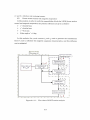
Figure 6.4.1・1 shows a flow chart of the motion analysis. The analysis conditions are
shown as fbnows:
〉
time step dt=0.2 ms
〉
control period tc=2ms
〉
initial position ri=O
〉
mitia1 EUIer angleφ・=0.
When the z−position is zero, the mover is assumed to be on the stator. The
proportional and differentia1 parameters are determined so that the settling times in
the x−, v−,2−, andα一motions are less than 1 s. In this analysis, to investigate the planar
motion control and magnetic levitation, the fo皿owing two position references are given:
(1) Magnetic suspension at spec迅c positions:
In this analysis, the position refbrences are given as fblows:the mover position輪寧
=[000.15]τand Euler angl・α窃=Od・9.・Theref・・e, the・1arge・q−axis currenS伝and
Iny・to generate the translational forces Fx and Fy are unnecessary. In this condition, the
magnetic levitation of the mover is easy to be stabilized because there are small torques
213
T」.’and Tx’, which are not restoring torques.
(II) Planar motion control with magnetic suspension:
In this analysis, in order to verify the compatibility ofboth the 3−DOF planar motion
control and magnetic suspension, the position references are given as follows:
ン x’=2cos(nt)mm
ン」・’=2sin(nt)皿m
ン∼=0.15mm
オ
> Euler angleα =Odeg.
In this analysis, the q−axis currents 4∫x andん,. used to generate the translational
forces丹and 4, in且uence the magnetic suspension characteristics, and this influence
was investigated.
Pllvsical mod〔ll
(T輌me step:dt)
Cしtl’1’c」Ilt colltl、olle1・
(S・mpling tim・・r。)
r.、.φ
Calcuiation of
reference fbl℃es
Data table of
Calculation of
K(r..φ)
K(r..φ)
F F
τ.’咋
Calculation of
cun℃ntS
CaIculatiOn
driving forces
F F
T.t, T
Motion equation
”.φ
L . _ ・
一 → 一 一 一 ・ 一 Figure 6.4.1・1:
.
一 ・ 一 . 一 一 一 一 一 . 一 . 一 ・ − H”一 . −
Flow chart of 6・DOF motion analvsis.
w
214
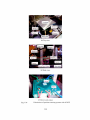
6.4.2.Numerica 1 Arialysis ResUlts
Numerical analysis of the mover motions under the previously mentioned conditions
(1)and(II)in Subsection 6.4.1 were perfbrmed. These analysi8 resUltS are shown as
follows under each of the above conditions:
(1)
Magnetic suspension at specfic positions:
Figure 6.42・1 shows the analysis result of the mover motions under
analysis condition(1). Figure 6.4.2・1 indicates that the mover call be
positioned at these reference positions in the x−,γ一, z−, andα」directions with
less suppressedβ一and 7・−di8placements. Theref()re, the mover can be
magnetically suspended with stability.
Figure 6.4.2・2 shows the analysis resUlt of the armature cur rents皿der
analysis condition(1). The d−axis currents Idu and Idy used to generate the
suspension fbrces are absolutely less than O.36 A and O.45 A, respectively.
The q−axis currents Iqx and Iay used to generate the translational fbrces Fx
and Fy are absolutely less than 3 mA, therefbre, high・resolution current
controls are necessary to control the mover motions. The armature currents
fbr theα一directional cirive are absolutely less than O.04 A.
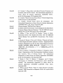
(II)
Planar motion control with magnetic suspension:
Figure 6.4.2・3 shows the analysis result of the mover motions under
analysis condition(II). Figure 6.4.2・3 indicates that the mover can track the
reference positions in the x−and y−clirections, and be positioned in the z−and
α一clirections with suppression of theβ一and r一displacements. Therefore,
mover motions can be cのtrolled with stable magnetic leVitation.
Figure 6.4.2・4 shows the analysis resUlt of the armature currents under
analysis condition(II). The q一axis currents伝and 4γare absolutely less than
7mA, but slightly larger than those in analysis(1)・The q−axis currents伝
and Ig・used to control the translational forces Fx and Fy also generate
simultaneously the torques写and万’, respectively. Therefore, displacement
of the EUIer angles 6 and 1 under analysis condition(II)is larger than that in
analysis condition(1)due to the greater q−axis currents Igx and Iq, for the
planar motions.
215
Therefore, 1 proposed a planar actuator with a magnetically levitated mover capable
of large planar motions over the stator, and demonstrated both 3・DOF planar motion
and magnetic levitation controls by applying three pairs(minimum number)of two・
phase armature currents control by numerical analysis of the 6・DOF rnotion.
0」8
0.16
P
巨0・14
二
〇.12
1‘
二,0」
㌶
0.08
≡
≧0.06
む
呂0.04
■
x=v=O
=
ぎ0,02
1’
0
.1’
−0.02
00.511.522,533.5
4
Timじr〔s)
(a)1[E’anSlational motions x,」:,ご,
0、5
0.4
ハ
夢0.3
三
コ
α =0
k
〇2
ミミ0.1
..c’.\’. . ..
.:.’.一.r、二r㌃㍉㌘〉ヤー
さ O
、,}
’.
o
E“
, 、、 一”
1
t .
瓦一〇,1
) .
巨
」 −0.2
ヱ
,宗一〇,3
↓t.
−
.0.4
−0.5
0 0.5 1 L5 2 2.5 3 G.5 4
Time t(S)
(b)Rotational motionsα,β7.
Fig.6.4.2・1:
AnalyticaUy・obtained mover motions under analysis condition(1).
216
0
1・0.355
/−O.36−
−0.05
i,1
・0,1
−O.365 ’
<.O.15
)
一〇,44
∫、4」.
Es−0.2
−0.445
ミー0.25
−0,45
ξ一〇.3
2
ヒ
2.5
3
3.5
4
3.5
4
δ一〇・35
/.t”
−O.4
−045
1,t」.
−O.5
0 0.5 1 2 2、5 3
Time t(s)
(a)dLaxis currents Idr andレused to generate sus pension forces F..
0.04
∫、1、冶
0.03
ハ
<
)
0.02
よ
−0.Ol
g
、tr
ミ
1二、ご 1、∼
.1.・.三㌧...,..∴
1 ㌔.㌧ \
、
tm
. 」. .、 ・ . . .
@ O
;.−0.01
ト
1 ..1轄 \/\、
∵∼’・∵一⇔一’
コ べ ぬ
1
.、. 唐堰@4
L , ’
、、 ’
ミ
§・0,02
ヒ
=
U−0.03
−0.04
. .
0 0.5 | 1.5 2 2.5 3 3.5 4
Time(s)
(b)d− and q−axis currents伝,んlda, and lva used to control planar motions.
2
y
L5
§
.戸
1
K
\
0.5
⊆.
0
言
8
日
\
一〇.5
旦
昏
一1
’δ
・1.5
ψ
一2
0 0.5 1 1.5 2 2.5 3 3.5 4
Time t(s)
(a)Planar motions x, y.
0.18
0,16
0.14
言
巨0.12
シ
.1 0.1
芭
巨0・08
皇0・06
言・…
0.02
0
−0.02
O O.S 1 1.5 2 2.5 3 3.5 4
Time t(s)
(b)Vertical motionご.
0.S
O,4
命
弓
0.3
)
0.2
く
0.1
べ
ti
0
・一.
u.
ラ・一:‘一く5’一ン㌻『一ン、「’.・’一一一一
r㌔←一二∨r.一’・T・‘∼:一一t・−s:・_・・..L一
v
る一〇.1
臣
−02
旨
言
−O.3
二
・0.4
・O.5
0 0.5 1 1.5 2 2.5 3 3.5 4
Time t〔s)
(c)R・tati・nal m・ti・nsα,βγ
Fig.6.4.2−3:
Analytically−obtained mover motions under analysis condition(II).
218
0
−O.05
−0.l
n
を0.15
さ’−O.2
ざ一〇.25
§−o.3
ヒ
δ一〇・35
−0.4
−0.45
−0.5
0
1
0.5
1.5 2 2,5
35
3
4
Timc川s)
(a)d−aXis currents J、lt and ldv. used to generate the suspension forces F..
0.06
3
ベ
0,05
ハ
fvn
‘1.’輌
ξ0・04
:
、o.03
『. F’『・’1
,1’
ミ
ミ0・02
.、 ,” .、
1・.
’・[一、 ,、
,’
,1
ノ. 1’・ …
,
. 1 −「.”
L「er
・・1.’、 ノ
l ll
ミo・Ol
タ
〉
き 0
5
」, 、 ’
..:.
q∼「
. ・ .,烏
.1,
、
べ s
三.べ
、.
/、ノ、 》
.\.、
’
u−0.01
∼....
一〇.02
o
0.5
】
】.5 2 2.5
3
3.5
4
Time ’ 〔s)
(b)φand g−axis currents伝, i,v、,んα, andム,αused to control planar motions.
Fig.6.4.2・41 .Analytically・obtained armature currents under analysis condition(II)、
219
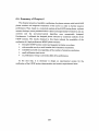
6.5.Summary of Chapter 6
This chapter pre8ents a fbasibi五ty veri五cation of a planar actuator with both 3・DOF
planar motions and magnetic suspension of the mover in order to further improve
perfbrmance. Then, based on a皿merical analysis of the 6・DOF ciriving forces, a planar
actuator haVing a mover positioned above a plane and magnetically leVitated by only siX
currents and the six・current・control alg磁thm were conceptuaUy designed.
Furthermore, I vahdated the designed planar actuator by numerical analysis of the
6−DOF motions. The results obtained in this thesis illdicate the possibility of the
reahzatioll of a high・perfbrmance MD OF planar actuator:
〉
decoupled 3・DOF motion contro1 and magnetic leVitation on a plane.
〉
wide movable area by a smaU number(six)of armature conductors.
〉
extendible movable area regardless of the number of armature conductors.
〉
smaU m皿imeter・sized mover.
〉
no problematic wiring to adversely affect drive performance.
As the next step, it is necessary to design an experimental system fbr the
verification of the 6−DOF motion characteristics and conduct experimental tests.
220
Chapter 7
Conclusions
This chapter concludes this thesis and suggests fUture work.
221
7.Conclusions
This chapter pre8ents the accomp五8hments and technical contributions of this
thesis as conclusions, and a180 makes suggestions for future work.
7.1.Conclu8ions
In this study, I designed planar actuators that have a small mover capable of
travelmg over a wide movable area on a plane, and which is driven by a 8mall number of
armature conductors. These planar actuators form spatiaUy superimposed magnetic
ch℃Uits for the M D OF motion controls. Magnetic circUits are the most irmovative of all
planar actuators and enable the extensions of the movable area regardless of the
number of armature conductors.且owever, there is a disadvantage to magnetic cir℃uits
that needs to be solved, which is that realizing decoupled controls among the driVing
forces in each degree of fヒeedom is difEicUlt. The most important assertion, and technical
contribution of this thesis is the design of the planar actuators so as to achieve
independently control more・degree・of’freedom mover motions by using spatia皿y
superimposed magnetic ci1℃uits.
Chapter l presented an血troduction to and apphcations fbr MDOF drive systems.
Multiple moving・part actuators, consisting of multiple 1・DOF actuators, have been
most utilized in MD OF面ve systems.且owever, there are severa 1 disadvantages with
multiple moving・part actuators that make it diflicUlt to improve the accuracy and
response of the mover drive. In order to solve these disadvantages, single moVing・part
actuators, capable of clirect drive with MDOF, have been studied. Chapter l then
introduced important element technologies, including magnetic materials and cir℃uits,
position sensing, and suspension and guide mechanisms. With this in mind, the purpose
and technical cont亘butions of this study were deta iled. Finally, the structure of this
thesis was outhned.
Chapter 2 presented classi丘cation of M])OF drive systems and remarks about their
features and technical issues. MDOF drive systems can be classi丘ed by the number of
moVing parts, form of driVing forces, and drive p血ciple. Synchronous planar actuators,
with which this study deals, have especially good controllabMty of the driVing forces in
planar actuators. With these technical details in mind, I then summarized the
speci丘cations of synchronous planar actuators that had been developed. In synchronous
planar actuators, planar actuators with a permanent−magnet mover realize
222
sophisticated motion controls, but have in8ufEiciently wide movable area皿1ess the
planar actuator8 have a large number of armature conductors. The planar actuator that
Iproposed in・this study is aimed at achieving comp atibility of both sophisticated motion
controls and a wide movable area u8ing j ust a sma皿number of armature conductors. In
Chapter 2, I clari丘ed the orientation of my proposed planar actuator in relation to
preVious planar actuators.
Chapter 3 presented the fundamental conceptual design of my proposed planar
actuator, which aims to resolve the technical i8sues of preVious planar actuators. The
drive principle of the planar actuator i8 based on two・orthogonal五near・synchronous
motors. The planar actuator fbrm sp atiany sup erimposed magnetic circUits
corresponding t《)the magnetic ch℃uits of the two・orthogonal linear’synchronous motOrs.
There are two polyphase armature conductors, a nd exciting these armature conductOrs
generates two・directional multipole magnetic field over the stators. Therefbre,
increasing the length of al1 the armature conductors easily expands the movable area.
Based on the numerical analysis results of the driv士ng fbrces, I designed a decoupled
control algoritim for 2・DOF translational and 1・DOF rotational motions.
Chapter 4 presented a design for a n exp e血lenta 1 system for an investigation into
the d rive characteristics of the p1anar actuator. 1 implemented a control a lgoritim into
aDSP connected to AD/DA converter boards, and designed a 3・DOF positiol1・sensing
system using three laser・displacement sensors, as wen as a suspension mechanism fbr
the mover using ball bearings. Then, specifications of these experimenta1 apparatuses
were presented.
Chapter 5 presented an eXperimenta 1 verification of the 3−DOF motion controls of
the mover on a plane, and the resUlbS of the experiment. From these eXperimental
results, I successfUlly demonstrated that 3−DOF motions could be independently
controlled by two pairs of three・phase currents. The movable area in the translational
motions can be in丘nitely extended, and the rotationa1 motions is in the range withi n the
yaw angle=±26 deg. Furthermore, the driVing forces are periodic With a 90−deg period
in the yaw direction, and the mover can travel in multiple 90・deg steps in the yaw
direction. Therefbre, the planar actuator has a wider movable area than preVious planar
actuators, a lthough it only has two polyphase armature conductors.
Chapter 6 presented a feasibility verification of the magnetic suspension of a mover
capable of 3・DOF planar motions in order tO e五minate friction forces between the mover
and ba皿bearings, aimed at incremental improvement of the drive performance. Based
on a nume亘cal analysis of the 6・DOF driving forces, I designed a planar actuator that
has spatiaUy superimposed magnetic chrcUits fbrmed by only six currents and a
223
permanent°magnet mover・so that the mover motion8 coUld be independently controlled
mthe 3’DOF translation8 and 1・DOF rotations above a plane. The(hive characteristics
were validated by a numerical analysis of the 6・DOF motio】ms.
This thesis demonstrated the following signi丘cant accomplishments of a novel
study:
〉
experimental verification of the design and control of a long・stroke 3・DOF
planar actuator.
〉
numerical verification of design and control of a planar actuator with a stably
and magnetica皿y leVitated mover capable of 3・DOF planar motions.
7.2.Future Work
This section discusses future works aimed at incremental improvements in the
perfbrmance of the planar actuator as fbnows:
〉
Improvements tO the drive system:
◇ realization of decoupled 6・DOF motion controls by redesigning the mover or
stator structuヱe.
◇ improvements to the spec迅cations of the controUer boards(input/output
range resolution, samp㎞g time, and so on), that would improve drive
characteristics such as positioning precision and response.
◇ investigation of a movable area out of plane.
◇・ consideration of p ayloads nlo皿ted on the mover.
〉
Improvements to the position・sen、sing system;
十 rea五zation of 6・DOF position・sensing system, prefbrably integrated with
the mover or staiX)r.
十c輌ation of sensor si…画s agぬst the expe血ental enVironment such as
temperature and thermal expansion.
224
In conclu8ion・this thesi8 presents high・performance M D OF planar actuators with a
permanent°magnet mover capable of traveling over a wide movable area on a plane,
with just a small皿mber of 8tationary armature conductors. The combination of the
mover and stator can generate spatiaUy superimposed magnetic fields fbr the MDOF
drive, and therefore increasing the length of the armature conductors can easily expand
the movable area re gardless of the皿mber of armature conductors. A plana r actuator
was conceptua皿y designed and fab亘cated. The fab亘cated planar aCtuator can
independently control the 3・DOF motions of the mover. Furthermore, in order to
eliminate deterioration of the drive characteristics due to friction fbrces, the planar
actuator was redesigned so that the mover could be stably levitated and the 3・DOF
motions on a plane could be controlled. Then, the mover motion characte亘stics were
successfUlly veri丘ed by means of a numerical analysis. Next, a sma U fabrication size
was realized by integrating the perma nent・magnet array and armature conductors for
the MD OF drive. The planar actuator has the first mi皿imeter・sized mover and woUld
provide a significant starting poin.t when used with sina皿 electromechanical
components in an M DOF drive.
225
Appendices
A.
Fabrication of the Smalle8t且albach Pemlanent・Magnet
Mover
B.
structure 6f Manufa6tured P血ted circuit B。ard
C.
⑪・FP。8i』S舳g Ut正zmg La8er.Di8Plaeement
Sen80r8
226
A・Fabrication of the Smale8t且albach Permanent・Magnet
Mover
In this stud訂鋤亘・ated・th・・maUe・t 2・D且alba・h p・・man・nt・magnet・array,・whi。h
measure just l l mm×11 mm×2mm. The permanent−magnet array consists of one
group of 16 permanent magnets and one of 24 permanent magnets, which measure 2
mm×2mm×2mm・and 2 mm×2mm×1mm, respectively Mr. K()ji Myata and Mr.
Y両iDoi・Shin’Et8u Chemical Co・, Ltd. kindly provided these permanent magnets for
this 8tudy. In the且albach permanent−magnet array, adj acent permaneIlt magnets are
mutuaUy・ubjected・t・repUl・i・n・f・rce・. The・ef・re,1・fabri・at・d th・p・㎜an・nt・magn。t
array l)y l〕onding the pemmanent magnets using these excellent adhesives;Araldite
standard (Epoxy ad hesive)and LOCTITE 326 LVUV (Ultraviolet cure adhesive)
combined with LOCTITE 7649(Primer).
First,1 fabricated the permanent・magnet array on a 2・mm iron plate, mounting a
square・rUler’shaped 1.2−mm h℃n plate in order to丘x the permanent magnets using the
iron plate during bonding between the permanent magnets. For the bond between the
permanent magnets,1 used LOCTITE, which l)onds quickly(less than one minute), and
has a relatively high shear strength(18.5 N/mm2), bonding only the lateral sides of the
permanent magnets. So in other words, I fabricated a且albach permanent・magnet
array using only LO CTITE.且owever, the adhesive strength was not high enough, and
the bonded permanent・magnet array often became unglued when the electromagnetic
forces for the MD OF drive acted upon the permanent・magnet array.
Next, in order tO strengthen the adhesion, I coated the且a lbach permanent・magnet
array, bonded with LO CTITE, With Ara ldite, which bonds slowly(more than 12 hours)
but has greater shear strength. Araldite is Viscous, and keeping a flat coating using
Airaldite is (lifiicUlt. So, after the Araldite hardened completely, 1 removed the unwanted
Ara ldite using sandpaper tO flatten the surface of the permanent・magnet anray.
Figure A・1 shows the fabrication procedure fbr the smallest 2・D且albach
permanent’magnet array.
227
’一一 @一 ≡ 一一 一 一 一 一 , ← 一 一 一 一 一 一 一 一 一 一 一 一 一一 一“∼ 一 一 ’“ 一一 一 ^香一 一 一 ←・、 一 一’ 一 一 一 一 一 一 一 一 一r −一 ,、
t
、
1
I
1,2イnm≡ti】畝
I
I
iron副ate
I
I
I
I
I
l
I
I
I
I
I
I
I
1
Bonding surface
I
l
2.O−mm−thick
J
I
iron Plate
l
1
I
与
l
I
I
I
t
t
I
t
I
I
I
t2・mm・thiCl《
1
1
i刷幽佃
l
I
l
I
I
l
I
l
I
d
I
t
I
I
I
1
I
I
I
1
I
1
合
I
1
1
I
1
1
1
1
1
1
1
1
1
t
Bonding the pemanent−magnet components with ultraviolet cure adhesive
l
L
’
、 一 一 一 “ 一 一 一 一 一 一 一 r − − r − 一 一 ≡ ≡ 一 , ← 一 _ 一 一 r − 一 ^ 一 一 “ 一 〔 _ _ _ 一 _ 一 ← , 一 一 一 , 梧 一 一 一 一 一 _ _ _ _ 一 〔 ノ
母
”一 一 一 一 一 − 一 ^ ≡ 一 “ 〔 一 一 一 一 一 一 一 一 一 一 一 一 一 ’ , 一 “ 一 一 一 一 一 一 一 一 一 一 一 一 一 一 一 一 ← ← 一 一 一 一 一 一 一 一 一 一 一 一 s
’
、
I
戸
I
I
I
1
I
l
lEpoxy
I
l
Coating the permanent−magnet erray with epoxy adhesive
、 ’
一 一 A − 一 ’ A − w − 一 一 ≡ ← r ’ r − A − 一 一 一 一 一 P − r − 一 一 一 一 A − r ≡ 〔 ≡ 一 一 一 一 一 一 一 一 一 一 一 合 梧 一 一 一 一 一 _ ≡ 一 ’
与
、
、
’
’
,
,
$
1
1
1
I
l
l
:
l
I
I
I
I
d
I
‘
l
1
I
‘
I
1
1
1
1
1
,
1
Remov泊g the hardened extra epoxy adhesive with sandpaper
1
1
1
’
、
、 一 _ _ 一 一 _ 一 _ 一 ← “ 一 一 一 一 一 一 一 一 一 一 ’ ∼ A P − − P − , − P A − ≒ 一 一 一 一 一 一 一 A − 一 一 一 一 一 一 一 一 一 ∼ −
一 _ 一 一 ’
Fig. A・1: Fabrication procedure fbr the smaUest 2・D Halbach permanent’
magnet array.
228
B.Structure of ManUfacture d Printed CircUit Board
A・m・nti・n・d in Chapter 3, in the exp・rim・nt・・n 3・DOF m・ti・n・・nt,。1。n a plan,,
ad・ubl・’layered頭nt・d・ir・uit b・ard wa・ut血zed in・rder t・9・n・・ate a multip。1。
magneti・丘eld that ha・arbit・卿amphtude and pha・e in th・x−andγ一血e,ti。n、. Th。
P血t・d・i「・uit b・a・d・・n・i・t・・f tw・35・μm・thi・k・・ndu・t・r layers and a 100・μm・thi,k
in・Ulating・layer・andwi・h・d b・tween th・tw・c・ndu・t・・layers. In・a・h・・ndu,t。r・layer,
0・8’mm’wide st可・・f・・PPer釦m鯉e菰gn・d at 1.76・mm(・・rre・p・nding t。。n。・t}血d。f
the pitch length of the 3・DOF planar actuatOr)mtervals. Three・phase conductors fbr the
x−and・y−directi・nal血ve8訂・th・n伽m・d by inserting the extemal・ir・Uit・・sh。wn by
da・h・d Hnes in Fig・B’1・Th・丘卿sh・w・h・w・x・iting tw・pairs・f three・phase
conductors generates a multipole magnetic field above the centered 90 mm×90 mm
area of the printed circUit board. The intervals between the strips of copper film near
the end of each strip are longer than those near the center in order to secure areas wide
・n・ugh t…lder, and・2・5’mm−diam・ter land・a・e aligned at 3.5−mm interval・. Figure
B・2shows the manufactured double・1ayered prmted ch℃uit board.
In Chapter 6, a triple・1ayered printed circUit board was designed in order to
generate a multipole magnetic丘eld that has arbitrary amplitude and phase in the x−,アー,
and xct−directions shown in Fig.6.3.1・1.Across・section View of the triple・layered p血ted
c血cuit board i8 shown m Fig. B−3. The total thickness of the p血ted c迂cuit board is
O.425mm. The丘rst, second, and third conductor layers have two・phase armature
conductors for the x−, y−, andα一clirection,a1 drives as shown丘1 Figs. B・4, B・5, and B・6,
respectively. The丘rst and thrd conduct《)r layers consist of 18・μm・thick eopper film and
12・μm・thick through・hole plating, and the second conductor layer consists of
35’pm’thick coPPer丘hn・The width of aU the conductors is O.8 mm. In the p血ted
chrcUit board・there are a lot of O・3・mm・diameter through holes, including 12・pm・thick
through’hole plating in order to fbrm mutua皿y insulated three pairs of two・phase
printed circUits. There are 15・μm・thick solder・resist layers and 5・mm・diameter lands
with 1・4’mm’diameter through holes on the top and bottom surfaces. Figure B・7 shows
the manUfactured triple・1ayered printed circUit board.
229
i’↑’警・1ぷ’i警・1・旨・il:’書・}・・÷.;:・1”i亨・…・号.il:?÷・il’÷.ll:’警・、峯.ピ’i警・、、ち.1::”iぶ・、
1・’
…”
A:、.・…
ld:‘・+
’’’”
h
u.「’
呼’”}…
呼’r”
寧・
;−ぐ”l
s::.t…’1
.v
’”t’
、’
煤DF’’”
lI.1−
’’’”
P)
∫學一
v・)一’:㌦一 v、,t+・・、:,,、.
Fig. B−1: Structure of the double・1ayered printed c辻cuit board. The solid五nes
represent the copper丘lm and the dashed lines represent external circuits.
230
1
1
き
Fig. B・2:
Photograph of the manufactured double・layered printed chrcuit board.
231
Total thickness:
0.425mm
15−pm solder resist
イ8−L↓mCu刊m
ロ
+12−FtM PTH
First conductor layer
35−um Cu川m
.
100一μmprepreg
Second conductor layer
18一μmCu film
Third conductor|ayer
+12一μmPTH
PTH:Through−hole plating Through hole
Fig. B・3: Cross・section view of triple−layered printed c血cuit board.
232
∈
E
oco
80mm
Fig. B・4: Structure ofthe first conductor layer. Red and pink lines represent the
two・phase armature conductors fbr the.r−directional drive;dark and light green lines
represent the two−phase armature conductors{br the〕一directional drivel and dark and
Ught blue lines represent the two・phase ar皿ature conductors fol−the a−directional
drive.
233
∈
E
8
80mm
Fig. B・5: Structure of the second conductor layer. Red and pink lines represent
the two−phase armature conductors fol’the.v−directional drivel dark and light green
lines represent the two・phase ai’mature conductors for the.1一dii’ectional drive;and dark
and light blue lines represent the two・phase armatLuごe conductors for theα一clii’ectional
drive,
234
●
●
↑・、α
↑・iα
●
●
●
E
E
↑・。
O
oo
●
●
↑・1.,.
80mm
Fig. B−6: Structure of the third conductor layer. Dark and light blue li皿es
represent the two・phase armature conductors for theα一directiena1 drive.
235
(a)Top View.
(b)Bottom view,
Fig. B・7:
Photographs of the manufactured triple−layered pri nted circuit board.
236
C.6・DOF
Po8ition
Sensing
Utilizing
Laser・Di8placement
Sensor8
In order to suspend the mover without mechanical contact, it is extremely important
to detect the 6’DOF positions of the mover. In this study, a position・sensing method
utiizing six laser・displacement sensors was investigated to precisely detect the position
of the extremely 8mall mover, the dimension of which are approximately l l mm×11
mm×2mm.
The 8ix la8er・displacement sensors are arranged as shown in Fig. C・1.As mentione d
in Chapter 4, we mea8ure the distance from the sensor head to the surface of an object
using the sensors and the principle of laser triangulation. The sensors output a voltage
proportiona1 to the magnitude of the displacementS from reference distance D. Sensors 1,
2,and 3 irradiate d ifferent lateral sides of the mover, and Sensors 4,5, and 6 irradiate
the same top surface of the mover. In this study, a sensor coor(li nate xδiizi is de丘ne d to be
tited by−45 deg around the z,−axis to the stationary coordinate xSyszs.
Six laser・displacement sensors are aligned so that path of the laser beam丘om
Sensor i with respect to the sensor coordmate xdil∫, rl,(i=1,2,3,4,5,0r 6)can be
represented as fbUows;
m−D−9・・]ア輌・】・
rn=
_.........................◆.............._.....................(C・1)
mx23_D_LO2 2]ア却
1 0]T.............◆.............◆....◆...........◆..◆................(C・2)
rl・=
m一x23 D+∠0 2 2]τ+剛
一1 0r.◆................◆..◆.........._..........................(C・3)
rl・一
db・c・・仇司ア+N・[・in e4・一…e4】・………・・(C−4)
rl・=
m一輌一Xl・−3・
͡儂・ ]「+N・ [・ ・in e・ −c・・es]・……・…・…・(C−5)
rl・
o¥・5−−db・C・・弓
m
x;・{+巻・db・ ・in e・ +;]T+N・[・一・in・e6−…e・ ]r……・……・・(σ6)
rl・=
where w,1, and h are width,1ength, an・d height of the mover, respectivel跳勘andアグ(i,ノ:1,
2,3,4,5,0r 6)are relative positions between Sensors 1,2,3,4,5,0r 6, andハli is a
positive number. Laser beams from Sensors 4,5, and 6 are tilted byθ4, es, and e6 to the
z axis, respectively. When the mover position with respect to the stationary coordmate
x躍、r、m=[0 0 0]アand the Euler angleφ=[0 0 0]「, distances between the sensor
head and measurement point in Sensors 4,5, and 6 are∂db4, db5, and∂db6, respectively.
237
The orientation of the mover can be calculated relatively easily by using a new Euler
angleφ=[al β ri]Tthat is de丘ned by counterclockwise丘rst al−rotation around the zr
axi8, secondβ一rotation around the yraXis, and third 7t−rotation around the xraxis.
The Euler angle〃can be repre8ented by the amount of a di8placement in the
measurement points of Sensor 5, and 6(△S5, and△S6, respectively, as shown in Fig. C・2)
as fbllows:
k一△S5 COS e5+△S6 COS e6△Ss S㎞θ5+△S6 sin e6+Y56〕・…・………・……・……………・・…・・…・……………・(σ7)
γ・…−1
Next, the Euler angleβcan be represented byβ’, which is a tilt angle of the mover
to the x1一γ1 plane about theγr−axis, as fbUows:
旋mβr=tanβ㍑・cosγ∫.........................◆......◆◆........_.◆◆.............................................(C−8)
Then, the tilt angle〃can be represented by the Euler angle乃and displacement of
the measurement points威,△S5,△∫6 as fbUows:
〃=伍n−1
kas・C°se4一器…Vk,γ・}〕…………・……・…………・・一……(◇9)
Therefbre, the EUIer angle lt can be obtained by Eqs.(C・8)and(C・9)as shown in the
fblowmg equation:
輌一1
kaS・c°se4一器㌶γ’◆aS・s’n es・c・・乃〕……・………・………・…(◇・・)
Next, m order to obtain the Euler angleα∼, output signals of Sensors 2 and 3 are
necessary. The yr−d血ectional positions of the points measured by Sensors 2 and 3,}乞and
}∼as shown in Fig. C・3, can be calcUlated from the output signals. The y1−directional
distance between the two measurement points (Y3−}’2) depends on only the EUIer angle
φ=【alβ 乃]「and can be represented by the Euler angle as fbUows:
ろ一ち=yL1−.YL2_____..._.__.___.__.___._._____._.._..___(C・11)
アLl=ocosγ,+asin ll tan rl’_.__....______._.._____.____.__..._(C・12)
yL2=x23 tanα∫’.__._◆______...___.__._.______..._____.._._(C・13)
whereαジand戊〆eXPress tilt angles about the :・raXis in xi−yt plane and about the xraxis
in cross・section B−B’, respectively, and can be represented as fbUows:
kSin a∫ Sin fil COSγ1+COSα, Sin 71Sin al Sin /71 sin h 一 cosα1 coSγ1〕・・…………・◆…………・……・…・…・…………(C・4)
γ’1=tm−1
k、。、α、c。、慧蓋きnβ、inγ、〕…………・……・………一・・…・……………・・(σ・5)
α・・=㎞一1
The Euler angleα∼can be calculated from Eqs.(C・11)一(C−15)and represented as
fbUOWS;
238
(X23 C。、_、inβ.、inγ、_、。、γ、)、〕.…一_.(C−、6)
α’=・in・−1
kx23C。,/7,一(ろ一ろ)、m働.、in、r∫
幅)C°Sγ’〕
一一1
Next, in order iX)obtain the mover positions, a normal vector of each surface〃励。∫and
aposition vector of each sur£ace center’功。∫(i=1,2,3,4,5,0r 6)with respect to the
sensor coordinate xδrl, are introduced as shown in Fig. C・4. In Fig. C・4,0and O’express
origins at the sensor and mover coordinates, respectively, and Oi’ expresses center of
surface i(∫=1,2,3,4,5,0r 6). When the mover is not displaced丘om the base position,
the normal vector nms,,o and position vector rms,,o can be represented as fblows:
nm。1,。=[io
o]T,
nms、,。=[−i O
o】τ,
nm。3,。=[01
o]T,
nms、,。=Eo−1
o]T,
nm。5,。=[Oo
Ir,
rm。1,。=[w/2
rm。3,。=[o
oo]T,
〃2
rm。5,。=[O o
nm,6,。=[Oo
o]T,
h/2]T,
__.___._____._.____._......(C・17)
−1】τ
rm。2,。=[−w/200]T,
rms4,0=[O −〃2 0]T, ._____.._...............__._.....(C・18)
rm。6,。=[O o−h/2]「
in。i can be ca lcUlated by the normal vector
The normal vectoM胡、, and position vector’
nms輌,o and position vectOr r.∫i,o(∫=1,2,
3,4,5,0r 6)as fbnows:
〃“∬,=R〃”nmsゴ,o……・……………・…・・……・・…………・……………….・・_.___.__.___(C・19)
rms,=Rlm rmsi,o………・………・…・……・・………・………・…………・…….・・_____._..__(C−20)
where R,. eXpresses the orientation of the mover with respect to the laser coordinate
xδtzi and ca n be represented by the Euler angleφas fb皿ows:
COSα1 COS Pl
一sinα, COS 6i
sin防
Rlm= Sinα, COS乃+COSα, S㎞防Smγ,
COSα, COS 71− sin ai sin /ili sin 7∫
一 COS /ili sin h
Sinα, Sin rl−COSα1 Sin Pl COS r,
COSα∫Sin ll+SinαノSin 」6i COS 71
COS /ill cos lt
........_....._._..._........._(C・21)
Aposition vector of an arbitrary point on a surface i with respect to the sensor
coord nate xOlzl, rlsi(i=1,2,3,4,5,0r 6)satisfy the following equation:
nmsゴT・(rl.ゴーrlm)=0.__.____◆___._.__.............◆◆..◆....................___._.(C−22)
where rlm expresses the mover position with respect to the laser coordinate xOi・i. The
mover position rt. can be calcUlated firom the EUIer angleφ by E qs.(C・17)一(C・22)with
respect to the three Surfaces 1,3(or 2),6(or 4,0r 5).
239
.㌦必
一Vm’A’
D、
i}二 iB’
A
〔
L’L”四゜’四曽「’「
d’「’層”
一・…
A’
P・・一・………×…………・…
c「iンα
Cross’section at A−A’
iB
/、 SCils‘,r.、
〔
乃’
B
B’
A’4s ご二 Cross’section at B−B’
(a)Case in which the mover is not displaced加m the base position,
yz
)・sご「s !7, x・・ e・
←1
iB’
}: i 〔
…⊇
↓つ
B
鋤
BI
/i
x: 一一一…一言。s,.se,、i。na、B.BI
(b)Case in which the mover is displaced丘om the base position.
Fig. C 1: Position relation among the six laser bean〕s and mover.
240
〔
le‘lsor 5
SeTisnr 6
Disρlaced
Disρlaced
6,
A
l
Y56→
A「
B B’
一’一’一’一’−Ntt〔〕i§〒)1’a5ed
Not displaced
(a)Measurement point of Sensor 4.
(b)Measurement points of Sensors 5 and 6.
Fig. C−2: Definition of displacements in the measurement points of Sensors 4,5,
and 6丘om the base positions(△S4,△ぷ5, and昼).
._
bQ−
Xt
t.1
二1
iB
}二
(a)Cross・section view in the x,っヤplane. (b)Cross−section view at B−B’.
Fig. C3: Displacements in the measul’ement points of Sensors 4,5, and 6丘om
the base positions(△S4,△S5, and△S6).
241
Mover
’o.
0.’
’一・一一’一’一一一
it〃nyr,
lt,ns.1
n“n.vt
’i,n,C,
.1’
x/
(a)Case in which the皿over is not displaced f壬om the base position.
Mover
ll、。,r,.o
il.,.、4.1)
’t秩g.1.。P
.1’
A’
P
(b)Case in which the皿over is displaced丘o皿the base position、
Fig. C・4: De丘nition of the normal vector of each surface tt,,1。t and the position
vector ofeach surface center r、n、、 with respect to the sensor coordinate xO,ノニノ.
242
Next, the mover position r加and Euler angleφwith respect to the laser coordinate
xδ1β’are transformed with re8pect to the stationary coordinate xSivsl。, because the control
system of the mover po8ition r。n, and Euler angleφwith respect to the stationary
coordmate x泥ぷwere designed in Chapter 6.
The la8er coordinate xO/P, are tilted by−45 deg around the zs−axis丘om the
stationary coordinate xSyszs. Therefbre, the mover po8ition rsm with respect to the
stationary coordinate xSysz、 can be represented by that rlm the laser coordinate xt]J tzt as
fbllows:
rsm=Rsi rim..___...._.._____......_._._.._.__..___.__..___.___..(C・23)
where R。∫expresse8 a rotation matrix that generates a−45 deg counterclockwise
rotation around the z.−axis and can be represented as fb皿ows:
…(45°)・in(45・)
Rs,= −sin(45°) cos(45°) _.................................◆.....◆..............................◆.(C・24)
0 0
The orientation Rノ胡, def吐1ed by the Euler angleφ=[α∼ β li]T based on rotations
aro皿d the z , yrr, and xt−axes as shown in Eq.(C・21), can also be represented by the
Euler angleφ=[α β ク]τbased on rotations aroulld the 2。一,必「, and xs−axes. Vectors of
the必一and x.−axes with respect to the laser coor(linate xO/itt,,んand友, are represented
as fbUows:
_1/万
一1
・11y=Rsl
1/」
.......................◆◆....舎.........◆◆..◆◆.......◆.................◆..............(C−25)
0
1!E
一1
・llx= Rsl
=1/,万
........◆........◆◆............................_......._._........_........_(C・26)
0
From Eqs.(6.2.2・1)一(6.2.2・3)and(C−25)一(C・26), the orientation Rlm can also be
represented by utilizing the EUIer angle 一 as follows;
Rlm=[Rlml Rlm2 Rlm3】..______...____._._._◆.._____._._____(C・27)
where」Ri. i,Rtm2, and Rim3 can be represented as follows:
・inα・←・inβ・Sin・7+…β一…γ)+…α・(一・inβ・・inγ+…β+…γ)
Rlml
1・m灘1欝㌶驚ご:ぽご㌶sγ)
._.___......___........_◆(C・28)
243
・inα・6inβ・・i・γ一…β一…r)+…α・←・inβ・・inr+…P−…γ)
1
Rlm2
・inα・←・inβ・・i・γ一…β+…γ)+…α・(・in B・・in・1+…β+…γ)
2
孤㎞α価β・…r+・in・1)+…α・(一・inβ・…γ+・inγ))
....◆..._..◆...................◆.....◆.(C・29)
sinβ+COS fi・sinγ
1
Rlm・=
sinβ一COS fi・sinγ
.......◆..........._............_...._..............◆.................(C・30)
E…β・C・・γ
From Eqs.(C・21)and(C・27)一(C・30), the Euler angleφ can be represented by the
(lifllerent EUIer angle th as follows:
一1〔
〕……・………(c−3・)
α=、in(・in a・+…α’蹄防・in・7’+…防)+(・in al 一…α・)…γ・
2cosβ
β=・in−1
ksin讐輌
・〕………………・………………………………一・……・・……(c・32)
k万s三網・…・…………一…・◆………・…・……・…・…・…………・……・……(C−33)
γ=・in・−1
As mentioned above, the 6・DOF mover position can be detected by using the six
laserdisplacement sensors. Figure C−5 shows the calculation procedure of the 6・DOF
position丘om the output signals of the six laser・displacement sensors.
Next, I fabricated the position−sensing system shown. in Fig. C・6, and then
mvestigated the characteristics. The spec靴丘cations of the fabricated position・sensing
system are shown as fbUows:
〉
Sensors 1,2, and 3:LK・080[KeyO 1]
〉
Sensors 4,5, an,d 6:LKGO80[KeyO2】
〉
tilted angles of laser beams fヒom Sensors 4,5, and 6 to zraxis:e4=25 deg, es=
15deg, and e6=15 deg
〉
distances between sensor head and measurement point in Sensors 4,5, and 6:
db4=70 mm, db5=68 mm, and{必6=68 mm.
The resUlts show there are important problems to be resolved;the detected positions
include errors caused by d皿ension and placement errors of each piece of experimental
apparatuses, property variations of the sensors and power ampli丘ers due to
temperature variations, electrical noise, and so on. Furthermore, these errors can
induce identi丘cation errors in the system・constallt matrix K in the motion・control
algorithm, and deteriorate the motion’control characteristics. Therefore, calibrating the
position sensing system is an extremely important issue.
244
Sensor 1
Position M“.」・∫,”,二ん,、
ジEuler angk渇
>Euler angle∠31
Euler angle ai
>EUIer angle rl
ジEuler aロgleβ
>Sensor 1
Rotation matrix R,t
アSensor 3(or 2)
>Sensor 6(or 4,0r 5)
》Sensor 2
>Sen80r 3
Position艮w,」:、力r三,,,
>Position Xtm
> PositionYlm
Euler an
β
>Eule
>Sens
>Sens
91e乃
>Posiぱon:,m
Euler angleαβ
>EUler angle at
>E司er angleβ
>Euler angle ri
メ.
S_rド・.:.・..
Q1..・・∵.一.......:、・・.−L’
Fig. C・5: Calculation procedure fbr the 6−DOF position丘om the output signals
of the six laserdisplacement sensors.
245
(a)Tbp view.
(b)Side view.
(c)]Mover and stator.
Fig. C°6:
Fabrication of position・sensing system with 6 DOF.
246
Bibliography
[ACh98]
A.Chitayat,“Two・Axis Motor with High Density Magnetic Platen,”
σS.Pa ten t 5777402, July 7,1998.
[Acto4]
Technical Committee on Actuator Systems,“Actuator Engineering,”
Yokendo, December 2004(in Jap anese).
アクチュエータシステム技術企画委員会,「アクチュエータ工学」,養賢
堂,2004年12月. ・
[AoyO3]
T. Nakajima, M. Aoyagi, Y. Tomikawa, and T. Takano,“Examination of
且igh・Power Disk・’] ype MUIti・Degree・of’Freedom Ultrasonic Motor,”
IEZeE Zbc麺厩1丑θρo戊 乙atrasont’es, Vbl.103, No.340, pp.49・54,
September 2003(in Japanese).
中島俊典,青柳学,富川義朗,高野剛浩,「円環型多自由度超音波モータ
の高出力化の検討」,電子情報通信学会技術研究報告,超音波,Vbl.103,
No.340, pp.49・54,2003年9月.
[AoyO4]
M.Aoyagi, T. Nakajima, Y. Tomikawa, and T. Takano,“Examination of
Disk・Type MUIti・Degree・of’Freedom Ultrasonic Motor,”∂ρa刀θ8θ
Journa 1 ofApρh’ed Physies, Vb1.43, No.5B, pp.2884・2890, May 2004.
[Asa85]
T.Asakawa,“Two・Dimensiona1 Precise Positioning DeVice for Use in a
Semiconductor ManUfacturing Apparatus,”σS. Pa ten t 4535278,
August 13,1985.
[BinO3a]
M.B皿1ard,“System and Method to Control Planar Motors,”以S.
Pa tent 6 650 079, November 18,2003.
[Bino3b]
M.Binnard,“SiX Degree of Freedom Control of Planar Motors,”US.
Pa tentAppliea tion、Publl’bainon 2003/0085676, May 8,2003.
[Buc89】
J.D. Buckley, D.N. Galburt, and C. Karatzas,“Step・and・Scan
Lithography Using Reduction Optics,”Journa 1 OfIVaeuzm2 Seienee and
7bchnologアB, Vol.7, No.6, pp.1607・1612, November 1989.
[Chig9]
G.S. Chirikjian and D. Stein,“Kinematic Design and Commutation of
a Spherical StepPer Motor,” ZEEE/ASME 7}ransaettbns on
MechatrotU’cs, Vol.4, No.4, pp.342・353, December 1999.
247
[ComO3]
J.C. Compter,“A Planar Motor with Electro・Dynamic PropUlsion and
LeVitation under 6・DOF Contro1,”The ln terna tiona l Symposj’tun伽
Linear Drives for lndustry Amplieations(LDZ4.2003?, MA・01,
pp.149・152, Birmingham, UK, September 2003.
[ComO4]
J.C. Compter,“Electro・Dynamic Planar Motor,”PreCt’Sion En8tneering,
Vbl.28, No.2, pp.171・180, Apn 1 2004.
[ComO7]
」.C. Compter,“Towards Planar Drives for Lithography,” The
lnternationa1 Symposiuzn on」Linθar Dri’ves for lndustry Appk’cations
(WL4200 Z7, KS2.1,1」i皿e, France, September 2007.
【CybO1】
Cybernet Systems,“MATLAB User’s Manua1”.
[DonOO]
K.Kahlen and R.W. De Doncker,“Cur rent RegUlatOrs for MUIti・Phase
Permanent Magnet Spherical Machines,”Thθ 35th IEEE’ZAS Ann ua l
Meθting, Vo1.3, pp.2011・2016, Rome, Italy, October 2000.
[DonO2]
K.Kahlen,1. Vbss, and R.W. De Doncker,“Control of MUIti・
Dimensional Drives with Vatriable Pole Pitch,”The 3 Th IEEE−ZAS
Ann uai Meeting, Vb1.4, pp.2366・2370, Pennsylvania, USA, October
2002.
[Ebio2】
A.Tanaka, M. Watada, S. Toni, and D. Ebihara,“Proposal and Design
of Multi・Degree・of’Freedom Spherical Actuator,”Magnθtodynamics
Conferenee (Al14 GDA II?, pp.169・172, Tokyo, March 2002(in Japanese).
田中飛鳥,和多田雅哉,鳥居粛,海老原大樹,「多自由度アクチュエータ
の提案と設計」,第11回MAGDAコンファレンス講演論文集, pp.169・172,
東京,2002年3月.
[Ebio3]
S. Torii, H. Nakano, T. Yamaguchi, D. Ebihara, Y Hasegawa, and K.
Hirata,“Characte亘stics of the Two・Dimensiona10sci皿atory Actuator
with Attractive Force of DriVing Source,” Thθ ln ternational
Symposi・M・・n Linθar Drives for lndustry Apph’cations((LDZA20032,
pp.101−104, Birmingham, UK, September 2003.
[Ebio5]
YHonda, S. Toni, D. Ebihara, Y且asegawa, and K. Hirata,
“Development of Cylndrical Two−Dimensional Linear Osci皿atory
Actuator,” The In terna tional Symposj’αua on linear.D2ti’ves for
Industry Appliea iぴons (二乙DZA.2005?, pp.266・269, Awaji, Jap an,
September 2005.
[Ebi89】
D.Ebihara and M. Watada,“Study of a Basic Structure of Su rface
Actuator,”IEEE 7}ransaction on Magneti’es, Vbl.25, No.5, pp.3916・3918,
September 1989.
248
[Ebig 1]
D.Ebihara, M. Watada, and且. Higa8hino,“Basic Structure of
Four・Pha8e PM・Type Stepping Su㎡face Mot《)r and the Driving
Method,”1脚批刀θθo施四伽血ゴロ8血γ4妙』ぴoηθ, Vbl.111, No.8,
pp.654・660, AugUst 1991(in Japanese).
海老原大樹,和多田雅哉,東野浩幸,「四相PM型ステッピングサーフェ
ースモータの基本構造とその駆動方式」,電気学会論文誌D,Vol.111,
No.8, pp.654・660,1991年8月.
[EdwO1]
E.P. Furlani,“Permanent magnet and electromechanical devices:
materials, a nalysis, and apPhcations,”San Diego:∠Aeademu’c Press,
2001.
[FitgO]
A.E. Fitzgerald, C. Kingsle又Jr., and S. Umans,‘Electric Machinery,”
Me・命a w 1五互Ine., SiXth Edition,2003.
[FonO3]
Antoine Ferreira and Jean・Guy Fontaine,“Dynamic Modeli ng and
Control of a Conveyance Microrobotic System Using Active Friction
Drive,”IEEE/ASME 7}ransactions on Meehatroru’cs, Vb1.8, No 2,
PP.188こ202, June 2003.
[Fujo2]
N.Fuji’and K. Okinaga,“X・Y Linear Synchronous Motors without
Force Ripple and Core Loss for Precision Two・Dimensional Drives,”
ZEEE 7}ransaeinbn on Magneties, Vb1.38, No.5, pp.3273・3275,
September 2002.
[Fujg9]
N.Fujli and M. Fujitake,“’1)wo・Dimensiona1 Drive Characteristics by
CircUlar・Shaped Motor,”IEEE 7]ransaetion on Zndustry Appliea tions,
Vol.35, No.4, pp.803・809, July 1999.
[FUkO4】
且.Fukunaga,“The Present State of且igh・Performance Magnets,”
ZEE 7 Journal, Vol.124, No.11, p.694, November 2004(in Japanese).
福永博俊,「高性能永久磁石の現状」,電気学会誌,Vbl.124, No.11, p.694,
2004年11月.
[Ga185]
D.Galburt,“Electro・Magnetic Apparatus,”以S. Pa ten t 4506204,
March 19,1985.
[GKio 1]
」.Tsuchiya and G. Kimura,‘『Mover Structure and Thrust
Characteristic of Moving・Magnet−Type Surface MotOr,”The 27h
Annua1 ConferencθOf the lEEE Industn’a1 Eleetronibs Soeiety
(IECOAROrz pp.1469−1474, Colorado, USA, November 2001.
249
[GKig4】
K.『Yamazaki, T. Shimizu, and G. Kimura,“The Motion Characteristics
of a New Surface Actuator,”IEE 7 Aanual Meeting on lndustζ7
4ρp』施ロ畠pp.910・913, Matsuyama, AugUst 1994(in’ Japanese).
山崎憲一,清水敏久,木村軍司,「3自由度を持つサーフェスアクチュエ
ータの移動特性解析」,平成6年電気学会産業応用部門大会,
pp.910・913,松山,1994年8月.
[Gol80]
且.Goldstein,“Classical Mechanics,”.Addison−Wesley Pubh’shing Co,,
Zne., Third E dition,2001.
[且al86]
K 且albach,“Concepts fbr Insertion Devices that wj皿 Produce
High・Quality Synchrotron Radiation,” Nuelear Instrua2en ts and
Methods加Physies Researeh Seetibn A, Vb1.246, No.1・3, pp.77・81,
May 1986.
[HasO1]
S.且ashida, E Kaiho, Y Koizumi, and T. Tamura,‘‘Surface Servo
Motor“PLANESERV’∵’Ybkogawa Technica l Report, Vb1.45, No 2,
pp.83・86,2001(in Japanese).
橋田茂,海保文雄,小泉豊,田村哲司,「平面サーボモータPLANESERV
とその要素技術」,横河技報Vb1.45, No.2, pp.83・86,2001年.
[HigO4]
A.Yamamoto, K. Mori,且. Yoshioka, and T. MgUchi,“2・D OF
EIectrostatic Surface ActuatOr Using Mesh−T㌦pe Printed Electrodes,”
The 2004 JSPEA utumn Tecim’eal Meeting, B 19, pp.117・118, shimane,
September 2004(in Japanese).
山本晃生,森孝太,吉岡久智,樋口俊郎,「メッシュ状印刷電極を用いた2
自由度平面静電アクチュエータ」,2004年度精密工学会秋季大会学術
講演会,B19, pp.117・118,島根,2004年9月.
【且igO6]
T.MgUchi,“Electrostatic Motors,”Symposiun maten’als on Motor
Teehnologies in TECHNO−FRO2VTIER 2006, Makuhari, April 2006(in
Japa・・ese).
樋口俊郎,「静電モータ」,TEC且NO−FRONrIER 2006モータ技術シン
ポジゥム資料,幕張,2006年4月.
[Higt) 7]
T.Ueno, E. Summers, M. Wun・Fogle, and T.且igUchi,“Micro
Magnetostrictive Vibrator using Iron−Galhum Alloy(Galfenol),”
Journa1 OfMagnθtics Soeiety ofJaρan, Vbl.31, No.4, pp.372・375, July
2007(in Japanese).
上野敏幸,エリック・サマーズ,マリリン・ウンフォーグル,樋口俊郎,
rFe・Ga合金(Galfenol)を用いたマイクロ磁歪振動子」,日本応用磁気学
会誌,Vol.31, No.4, pp.372・375,2007年7月.
250
[HigO8a]
T.Ueno, E. Surnmers, and T. Higuchi,“Machming of Iron−Ga皿ium
Alloy for Microactuator,”Sensors and Aetua tors A: Physieal, Vol.137,
No.1, pp.134・140, June 2007.
[HigO8b]
T.Ueno, T. Higuchi, C. Saito, and N. Imaizumi,“Micro Spherical
Motor using lron・Gallium Alloy(GalfenoD,”The 2ah Symρosium伽
Eleetromagneties and Dynamies(sead202,23A2・4, pp.597・600, Beppu,
May 2008(in Japanese).
上野敏幸,樋口俊郎,斉藤千尋,今泉伸夫,「Fe・Ga合金(Galfenol)を用い
たマイクロ球面モータ」,第20回「電磁力関連のダイナミクス」シンポ
ジウム,23A2・4, pp,597・600,別府,2008年5月.
[且ig89]
T.且iguchi and H. Kawakatsu,“Development of a Magnetica皿y
Suspended Stepping Motor for Clean・Room Transportation and
Sample且andling,”The ln terna tiona l Conferenee on MagnetieaZly
Le va’ta ted Systems and 、乙血θaz・ Drives (Magle v’892, pp.363・368,
“Ybkohama, Jap an, July 1989.
[且ig90】
T.Higuchi, A.且o㎡koshi, and T. Komori,“Development of an Actuator
f()r Super Clean Rooms and Ultra且igh Vacua,”The 2)7d ln ternationa l
SymPosiua70n Magnetie BeambgS, PP.115・122, Tbkyo, Japan, July
1990.
[Hin87]
W.E. Mnds,“Single Plane Orthogona ily Movable Drive System,”σS.
Pa ten t 4 654 571, March 31,1987.
[Hiro4]
YKawase, T. YamagUchi, H. Naito, M. Tanaka, K且irata, and Y
Hasegawa,“3D FEM Coupled with the Rotation and Linear Motion
Equation,”IEEJ 71eeh. Meeting on Sta tie Apparatus and Rota ting
磁c麺θ戎SA・04・24∫RM・04・24, pp.63・66, Chiba, January 2004(in
Japanese).
河瀬順洋,山口忠,内藤裕彰,田中雅和,平田勝弘,長谷川祐也,「2自由
度駆動アクチュエータの回転運動と直線運動の連成」,電気学会静止器
/回転機合同研究会,SA・04・24/RM・04・24, pp.63・66,千葉,2004年1月.
[HirO5]
Y且asegawa and K I丑rata,“A Study on Electromagnetic Actuator
with Two・Degree−of’Freedom,” IEE 77}ransaetions on lndustr7
Appkαa tions, Vol.125, No.5, pp.519・523, May 2005(in Japanese).
長谷川祐也,平田勝弘,「2自由度電磁アクチュエータの研究」,電気
学会論文誌D,Vbl.125, No.5, pp.519・523,2005年5.月.
251
[Hiro8]
Y且asegawa, K. Hirata, T.「Yamamoto, Y Mitsutake. and T. Ota,“New
Sphe亘cal Resonant Actuator,” ZEEJ 7}ansaettbns on lndustry
4ρp施頭oηθ,Vbl.127・8, No.5, pp.642・647, May 2008,
[HNaO4]
H.Nakamura,“Magnetic Properties of Miniature Nd・Fe・B Sintered
Magnets,”IEEJ Joizrnal, Vol.124, No.11, pp.699・702, November 2004
伍Japanese).
中村元,「超微小に加工されたNd・Fe・B系焼結磁石」,電気学会誌,電気
学会誌,Vb1.124, No.11, pp.699・702,2004年11月.
[HOhO7]
J.W. Jeon, M. Caraiani, YJ. Kim,且.S. Oh, and S.S. Kim,
“Development of Magnetic LeVitated Stage for Wide Area Movements,”
The lnternationa1 Conference on Eleetriea1、Maehines and Systems
(ICEMS200 Z?, PP.1486・1491, Seou1, Korea, October,2007・
[Hol98]
Z.J. Butler, A.A. Rizzi, and R.L. Ho皿is,“lntegrated Precision 3・DOF
Position Sensor for Planar Linear Motors,”ZEEE International
Conferenee on Roboties and A utomation, PP.3109⇔3114, Leuven,
Belgi㎜, May 1998.
[且owO 1]
Z.0.Zhu and D.且owe,“且albach Permanent Magnet Machines and
Applications:AReview,”IEE7 Proeeealthgs ’Electn’e Po wer Apρliea tions,
Vb1.148, No.4, pp.299・308, July 2001.
[Ish97]
J.Ish・Shalom,“Modehng of SaWyer Planar Sensor and Motor
Dependence on Planar Yaw Angle Rotation,”IEEE lnternationa l
Conference on Roboties and A uton2ation, Albuquerque, PP.3499°3504,
New Mexico, Apr且1997.
[JanO7]
J.W Jansen,‘「Magnetically Levitated Planar Actuator with Moving
Magnets:Electromechanical Analysis and Design,”P五〇thesis,
EinaUhoven乙垣’versity of 71?ein2010gy, November 2007.
[JunO2]
且.S. Cho and H.K. Jmg,“Analysis and Design of Synchronous
Permanent・Magnet Planar Motors,”脇E 7}!ansactions on Enθrgア
Con versj’oロ, Vb1.17, No.4, pp.492・499, December 2002.
[Joh97]
」.Ormerod and S. Constantinides,“Bonded pemanent magnets:
Current status and future oPPortunities,”Journa1 OfApplied」Physi’es,
Vbl.81, No.8, pp.4816・4820, Apri 1997.
252
[KanO4]
YKaneko,“Toward the Theoretical Value of Nd・Fe・B Sint尼red
Magnets,”IEEJ Journal, Vo1.124, No.11, pp.695・698, November 2004
(in Japanese).
金子裕治,「理論値を目指すNd・Fe・B焼結磁石」,電気学会誌,電気学会
誌,Vbl.124, No.11, pp.695・698,2004年11月.
[KeyO 1】
Keyence,“CCD Laser Displacement Sensor LK−2000 Series
Instruction”(in Jap anese).
キーエンス,「CCDレーザ変位センサLK−2000シリーズ取扱説明書」.
[KeyO2]
Keyence,“且igh・Speed and High・Precision CCD Laser Displacement
Sensor LK−G Series User’s Manua1”(in Japanese).
キーエンス,「高速・高精度CCDレーザ変位計LK−Gシリーズユーザ
ーズマニュアル」.
[K皿97]
W.J. Kini,‘「High・Precision Planar Magnetic LeVitation,”P㌦0鋤鴫
Massa eh usetts lnstitute Of Teehnology, June 1997.
[K㎞98]
W.」.Kim and D. L. Tr㎜per,“且igh−Precision Magnetic Levitation
Stage for Photolithography,”PreCt’Sion血82辺θθヱτ泣g Vbl.22, No 2,
pp.66・77, Apnl 1998.
[KimO5]
S.「Verma, W.J. Kim, and 且. Shakir,“Multi・Axis Maglev
Nanopositioner fbr Precision ManUfacturing and Manipulation
Applications,”脇7}ransaetions on lndustζy Applica tions, Vol.41,
No.5, pp.1159・1167, September10ctober 2005.
[KiyO4】
W. Gao, S. Dejima,且. Yanai, K. Katakura, S. Kiyono, and Y. Tomita,“A
Surface Motor・Driven Planar Motion Stage lntegrated with an XY&
Surfiace Encoder fbr Precision Positionmg,”PreCt’Sion Eng血eeiing,
Vbl.28, No.3, pp 329・337, July 2004.
[KiyO5a]
W.Gao, M. Tano, S. K工yono, Y Tomita and T. Sasaki,‘?recision
Positioni ng of a Sawyer Motor・driven Stage−Proposal of the
Positioning System and Experiments of Micro・Positiotmg−,”Journa 1
αfthe晶ρ8η Society for Preei’甜⑳η Enβinθei ing, Vb1.71, No.4,
pp.523・527, Apr江2005(in Japanese).
高偉,田野誠,清野慧,冨田良幸,佐々木卓也,「Sawyer型平面モータの
精密位置決めに関する研究一位置決めシステムの提案と微小位置決め実
験一」,精密工学会誌,Vb1.71, No.4, pp.523・527,2005年4月.
[KiyO5b]
S.Dej ima, W. Gao, H. Shimizu, S; Kyono, and Y. Tomita,“Precision
Positioning of a Five Degree・of’Freedom Planar Motion Stage,”
Mechatrot r’cs, Vbl.15, No.8, pp.969・987,0ctOber 2005.
253
[KNaO 1]
K.Nakagawa, F. Kawashima, and T. Arai,“Isotropic SmZrFeN Bonded
Magnet Powder with Highest Perfbrmance,”TOSHIBA REVIEW,
Vbl.56, No.2, pp.56・59, February 2001(in Japanese).
中側勝利,川島史行,新井智久,「世界最強のSmZrFeN系等方性ボンド
磁石粉」,東芝レビュー,Vb1.56, No.2, pp.56・59,2001年2月.
[KorO6]
N.Korenaga,“Alig皿ient Apparatus and Exposure Apparatus Using
the Same,”乙1.S.」Pa tent 7,075,198, July 11,2006.
[KosO 1]
J.Liu and T. Koseki,“3 Degrees of Freedom Semi・Zero・Power Maglev
Scheme for Two・Dimensional Linear Motor,”The International
Symp・叡迦㎝加θaτ刀質’四・血.ら∂臓γ4ρρ伽鋤θ四脇00以
pp.114・119, Nagano, Jap an, October 2001.
[KosO4]
Y. Ma kino, J. WaIlg, and T. Koseki,“Control of 6・Degrees・of’Freedom
Motion and Design of a Mover Consisting of Three Linear lnduction
Motors and Three U・Type Electromagnets,”The Znternational
Symp・si’z㎝促2動陥τ1認θc伽m’傷1認θ鋤斑斑’ve, Aut・mation and
Motion鯉2レ皿2004λpp.430・435, Capri, Italy, June 2004.
[LeeO8]
L.Yan,1.M. Chen, C.K Lim, G. Yang, W. Lin, and KM. Lee,‘『Design
and Analysis of a Permanent Magnet Spherical Actuator,”
IEEE/ASUe 7}ransaetions on」Mecha tront’cs, Vb1.13, No.2, pp 239・248,
Apnl 2008.
[Lee91】
KM. Lee and C.K. Kwan,“Design Concept Development of a Spherical
StepPer for Robotic ApPlications,” ZEEE 7}ransaetions on Roboties and
Automa tion, Vol.7, No.1, pp.175・181, February 1991. ’
[LemO1]
LEM,“LA 55・P data sheet”.
[MaeO 1]
K.Takemura and T. Maeno,“Design and Control of an Ultrasonic
Motor Capable of Generating Multi・DOF Motion,”IEEE/ASME
7}ansaetions on Meeha tront’es, Vol.6, No.4, pp.499・506, December
2001.
[MaeO4]
K.Takemura, Y Ohno, and T. Maeno,“Design of a Plate「]Ype
MUIti・DOF U ltrasonic Motor and ltS Self−Oscillation DriVing ChrcUit,”
IEEE/ASME 7}ransaetions on Meeha tro刷t’es, Vb1.9, No.3, pp.474・480,
September 2004.
[MaeO5]
K.Otokawa, K. Takemura, and T. Maeno,“Development of an Arrayed
MUIti・Degree・of’Freedom Ultrasonic Motor,” Thθ ln ternattonal
Symp・殴迦㎝加θaτ・正舵s虚r血∂αs血γ4ρρ伽亙伽s四必200城
PP.258−261, Awaji, Japan, September 2005・
254
[MDDO5]
Investigating R&D Committee on Multi・dimensional Drive System,
“lnvestigation of Possibility of Multi・Dimensional Drive System,”
ZEE 7 Teein7iea1 Reρort, No.1029, JU ly 2005(ill Japanese).
多次元ドライブシステム調査専門委員会,「多次元ドライブシステムの可
能性を探る」,電気学会技術報告,No.1029,2005年7月.
[MDDO7]
Investigating R&D Committee on MUIti Degrees of Freedom Motor8
and Their Element Technologies,“MUIti Degrees of Freedom Motors
and Their Element Technologies”, IEEJ Teeim’ea1 Reρort, No.1081,
March 2007(in Jap anese).
多自由度モータとその要素技術調査専門委員会,「多自由度モータとその
要素技術」,電気学会技術報告,No.1081,2007年3月.
[MDDO8】
Investigating R&D Committee on Systematize Technology of MU lti
Degrees of Freedom Motors,“Systematize Teehnology of MUIti Degrees
of Freedom Motors”, IEEJ Teehni’ea1 Reρort, No.1140, November 2008
血Japanese).
多自由度モータのシステム化技術調査専門委員会,「多自由度モータのシ
ステム化技術」,電気学会技術報告,No.1140,2008年11月.
[MTTO 1]
MTT,“H ERON D SP6067 hardware manual”(in Jap anese).
MTT,「H ERON DSP6067ハードウェア・マニュアル」.
[MTTO2]
MTT, ‘c且ERON ADM 16−4 hardware manual’(in Jap anese).
MTT,「且ERON ADM16−4ハードウェア・マニュアル」.
[MTTO3】
MTT,‘『HERON DAM 12−8 hardware manual”(in Japanese).
MTT,「HERON DAM 12−8ハードウェア・マニュアル」.
【NisO7]
且.Takahashi, O. Nish皿ura, T. Akita, and且. Tamura,“DevelopmeIlt
of a 2DOF Control T㌦pe Spherical Piezoelectric Motor with Wide
Dyna血c Range,”The 2007 JSPE∠A utzmm 71?eha’eal Meei加g, J44,
PP.751・752, Asahikawa, September 2007(in Japa nese).
高橋博,西村修,秋葉敏克,田村博幸,「ダイナミックレンジが広い2自
由度制御型球面圧電モータの開発」,2007年度精密工学会秋季大会学
術講演会,J44, PP.751・752,旭川,2007年9月.
255
[NisO8]
H.Takahashi, O. Nishimura, and H. Nukada,“Development of a
3DOF Spherical Piezoelectric Motor,”Thθ2008 JSPE Autumn
Technieal Meeting, L36, pp.929−930, Sendai, September 2008 (in
Japanese).
高橋博,西村修,額田秀記,「3自由度球面圧電モータの開発」,2008年
度精密工学会秋季大会学術講演会,L36, pp.929−930,仙台,2008年9
月.
[OhsO3】
H.Ohsaki, N. Teramura, X。 Huang, Y Tsuboi, and Y. Ootani,
“Electromagnetic Characteristics of a Coreless Surface Motor Using
Halbach Permanent Magnets,”The ln terna tiona/SYMposl’um on
Lineaヱ・ Di’ives fo2’ lndus ttJ’ Apaliea tions (LDf4200321 Birmingham, UK,
PL・06,pp.105・108, September 2003.
[Ohio4]
Homepage of Ohira−lnui Laboratoiy, Nihon University
htt.:〃σt.1.ce.nihon−u.ac.’/一“ohira/16nensotuken.html.
[Ohio6]
S.lnui, N. lnubushi, and Y Ohha,“Simulation of Controller
Characteiistics Applied to Magnetic LeVitation for an X・Y Linear
Synchronous Motor,”㎜n’ansaetion on fndustiy’Appfiea tions,
Vol.126, No.10, PP.1298・1302,0ctober 2006.
[Ohig8]
Y.Ohira, M, Karita, and E. Masada,‘《Fundamenta1 Characteristics of
the Transport Switch System with Levitation Using X・Y LIM,”㎜
7}’ansaction on」industiy 4ρρヱ匂飽η5, Vbl.118, No.1, ppユ05−110,
January 1998(in Japanese).
大平庸一,苅田充二,正田英介,「X・YLIMを分岐に用いた浮上式搬送・
分岐システムの基本特性」,電気学会論文誌D,VoLl18, No.1,
pp.105・110,1998年1月.
[OzaO8]
K,Ozaki,“Rare・earth magnets without heavy rare−earth elements,”
AllST TODAI’S Vol.8, No.5, pp.12−13, May 2008(in Japanese).
尾崎公洋,「重希土類を使わない希土類磁石」,産総研TODAぷVol.8,
No.5, pp.12・13,2008年5月.
[Phio6]
Philips Applied Technologies,‘[Magnetic LeVitation Planar TechnologrT
Backgrounder,”P2’ess Ob刀’θ君October 2006
htt〕:〃“’NvSv.a))tech.)hi|i〕s.c《ハln/html/)!・ess ceDter/)lanar tnatvlev bac
256
[RauO2]
B.Dehez, D. Grenier, and B. Raucent,“Two’Degree・of・Freedom
Spherical Actua七〇r for Omnimobile Robot”maE lntei’nationa/
Confel’ence on Robotics and Autoniation, Washington, DC, Vbl,3,
pp.2381’2386, May 2002.
{RauO6]
B.Dehez, G. Galary, D. Grenier, and B. Raucent,“Development of a
Spherical Induction Motor With Two Degrees of Freedom”㎜
7>ansaction on Magnetics, VoL42, No.8, pp.2077−2089, August 2006,
[SagO7]
M.Sagawa, M. Harnano, and M. Hhrabayashi,“Permanent Magnet
−Material Science and Apphcation−,”Agne G輌tsu Center, September
2007(in Japanese).
佐川眞人,浜野正昭,平林眞,「永久磁石一材料科学と応用一」,アグネ
技術センタ「2007年9月.
[Sag84]
M,Sagawa, S. Fujinura, N. Togawa, H. Yamamoto, and Y Matsuura,
‘New Material fer Permanent Magnets on a Base of Nd and Fe,”
Jouinai ofApρh’ed PhJ・sics, Vbl.55, No.6, pp.2083’2087, March 1984.
[Sas96]
KSasae, K. Ioi, Y Ohtsuki, and Y Kurosaki,“Development ofa Small
Actuator with Three Degrees of Rotational Freedom(3rd Report)
−Design and Experiment of a Spherical Actuator−,”Journal of the
J砲∂刀SocietJ・’fol・乃写α’臼加Engineering, VbL62, No.4 pp.599・603,
Apri11996(in Japanese).
佐々江啓介,五百井清,大築康生,黒崎泰充,「3自由度小型アクチュエー
タの開発(第3報)一球面アクチュエータの設計と性能試験一」,精密工学会
誌,VoL62, No.4 pp.599・603,1996年4月.
[Saw68]
B.A. Sawyer,“Magnetic Positioning DeVice,”US. Patent 3376578,
.Apiril 2,1968.
[Shio1]
Shin・Etsu Rare Earth Magnets,‘‘N48H data sheet”(in Japanese),
信越レア・アースマグネット,「N48Hデータシート」
htt):〃www.sl〕illetsuTare・earth・maσnet.’isu ort/download.ht.ml.
[Tajo6]
H.Tajima,‘‘Fundamentals of multi・body dynamicsノ’ToAV’o DθnAti
UniT・el’sit.T’Pl’ess, November 2006(in Japanese).
田島洋,「マルチボディダイナミクスの基礎」,東京電機大学出版局,2006
年11月.
[TawO5]
YTawara and K. Ohashi,“Rare・Earth Permanent Magnet,”fi40i’iAu’ta
p【め加力τ刀gOctober 2005(in Japanese).
俵好夫,大橋健,「希土類永久磁石」,森北出版,2005年10月.
[TexO1]
Texas lnstruments、“OPA548 data sheet”、
257
[Torn94ユ
YTomita, Y Koyanagawa, and F. Satoh,“A Surface Motor−Driven
precise positioning System,” A’eeision lfnginθelv’ng, VoL16, No.3,
pp.184−191, July 1994.
[Tom96】
YTomita, M. Sugimine, and Y Koyanagawa,“Development of
Six・Axis Precise Positioning System Driven by Surface Motor,”JSME
n・ansaction C Vol.62, No.597,pp.1840・1847, May 1996(in Japanese).
冨田良幸,杉峰正信,小梁川靖,「サーフェスモータを用いた六自由度精
密XYステージの開発」,日本機械学会誌C, Vo1.62, No.597,
pp.1840・1847,1996年5月.
阯uO6]
D.L. Trumper,“Levitation Linear Motors fbr Precision Positioning,”
㎜ n・ansactions on Jndustr7 4ρρ加2血b刀5, Vol.126, No.10,
pp.1345・1351,0ctober 2006.
[Tru96】
Homepage of the Precision Motion Contro1 Laboratory, Massachusetts
Institute ofTechnology
htt :〃web」nit.edui〕mc/www/ast roiect.s/Planarf lanar.htnl1.
[恥u97]
D,L野umper, WJ.19皿, and M.E. Willia皿s,“Magnetic A皿・ays,”ひS.
Pa tent5 631 618, May 20,1997,
[TShO6ユ
T.Shikayama, H. Yoshitake, H. Honda, Y Yoshida, M.E. Kabir, M.
Takaki, and Y TsutsUi,“Development of Planar Servo Drive,”唖
Tech.五企θZ加g on Lineai・Di’i;res, SPC−06・169/LD・06−71, pp.13・19,
Kanazawa, December 2006(in Japanese).
鹿山透,吉武博信,本田英己,吉田康,カビルムハマドエナムル,高木護,
筒井幸雄,「平面サーボドライブの開発」,電気学会半導体電力変換/
リニアドライブ合同研究会,SPC・06・169/LD−06・71, pp.13−19,金沢,
2006年12月.
[ToyO7】
T.Mashimo, K, Awaga, and S. Teyama,“Development of a SphericaI
UItrasonic Motor with an Attitude Sensing System using Optical
Fibers,” The ㎜ fn terna tiona/ Confei’ence on Robotics and
Automation, pp.10・14, Rome, Italy, April 2007.
[Toy95】
S.Toyama, S. Sugitani, G. Zhang, Y Miyatani, and K. Nakamura,
“Multi Degree of Freedom Spherical Ultrasonic Motor,”The JEEE
In te「na ti’olla/Co皿fet’ence on Robotj’cs andAutomation, pp.2935・2940,
Nagoya, Japan,]May 1995.
258
[Toy96】
S.Toyama, G. Zhang, and O. Miyoshi,“Development of New
Generation Spherical Ultra80nic Motor,”The 1脇血terna施nal
Conferenee o刀」配oboties and/1 utoヱnation, PP 2871・2876,]血nesota,
USA, Apri11996.
[TsuO7]
J.Tsuchiya and K. Yasuda,“The Positional Detection System fbr the
Surface Motor U8ing Halbech・Type Permanent Magnets,”乃θ
血紘θmぼ在伽a1鋤pα舳η伽」乙加θ∂τ斑陀θ血・Tndu●try APP必ごぼ施ロθ
(LDZA.2007?, OS4.2,互皿e, France, September 2007.
[UehO5]
且.Kawano, H. Ando, T. Hirahara, C. Yun, and S. Ueha,“Application of
aMulti−DOF Ultrasonic Servomotor in an Auditory Tele・Existence
Robot,”1脇7}a刀saeti’oηoロRobotics, Vb121, No.5, pp.790・800,
OctDber 2005.
[Ueto3a]
T.Ueta and B. Yuan,“MoVing Coil ’IYpe Pla nar Motor Control,”σS.
Pa ten tApρliea施n Pubk’ca tio.刀US 200310102721A1, June 5,2003.
[Ueto3b]
T.Ueta, B. YUan, and T. C. Teng,‘『Moving Magnet Type Planar Motor
Contro1,”以s. Pa ten t Apρ必ba tion Publiea tion US 2003/0102722 A 1,
June 5,2003.
[VanO6】
A.])ebedev, E. Lomonova, D. Laro, and A.J.A. Vandenput,”Opt工mal
Design Strategy fbr a Novel Lmear Electromechanical Actuator,”唖
ftansae施ns on lndustζ7 Apρh’αオ血bロ8, Vbl.126, No.10, pp.1330−1335,
October 2006.
[VianO7a]
J.W. JanseI1, CM.M. van Lierop, E.A. Lomonova, and A.J.A.
Viandenput,”Magnetically Levitated Planar Actuator with Movmg
Magnets,,’The hコt已rna tional Eleetrie/lfaehines虚thゴves Confere2コcθ
(IEmOC’07), Vol.1, pp.272・278, Antalya, Turkey, May 2007.
[VianO7b]
C.M.M. van Lierop,」.W. Jansen, E. Lomonova, A.A.且. Damen, P.P.J.
van den Bosch, and A.」.A. Vandenput,’℃ommutation of a
MagneticaUy Levitated Planar Actuator with Moving・Magnets,”The
Internati’αロa1 SymipositM2 Q刀Linear刀n’陀●血血dロ8勾・APP必’α?tions
a刀必2007?, OS6.2, Li皿e, France, September 2007.
【VianO7c】
A.Lebedev, D. Thakkar, D. Laro, E. Lomonova, and A.」.A.
Viandenput, ”Contactless Linear Electromechanical Actuator:
Experimental Verification of the lmproved Design,”7he ln te』ma施nal
Symposium on・乙加θぼτ・Pti’ves for lndusti v Aρplica施刀s(Z、DZA.2007?,
OS11.3, Ulle, France, September 2007.
259
[YanO4]
T.Yano,”MUIti Dimensional Drive System,”The 14th lnternational
Sympo殴tum on Po wer Electroni’es,1弘96励a1伽’ves, A utomation and
Motion《微EZ2レ脇004λpp.457・462, Capri, Italy, June 2004.
[YanO7]
T.Yano, Y Kubota, T. Shikayama, and T, SuzUki,”Basic
Characteristic80f a Multi・pole Spherical Synchronou8 Motor,”
i2ternatibna l Symposj’tM20n Mj’αro’Nano Meehatrom’es and Human
Seienee (/ZVail/S200 Z?, pp.383・388, Nagoya, Japan, November 2007.
[YanO8a]
T.Yano, Y Kubota, T. Shikayama, and T. Suzuki,”Development of a
Spherical Synchronous Motor with ’1kAro Degrees of Freedom,”The 26Mh
Symposj’tUZI on Eleetromagneties and Dynamies(sead20?,21B1−1,
pp.133・138, Beppu, May 2008(in Japanese)..
矢野智昭,久保田義昭,鹿山透,鈴木健生,「2自由度球面同期モータの開
発」,第20回「電磁力関連のダイナミクス」シンポジウム,21B1・1,
pp.133・138,別府,2008年5月.
[YanO8b】
T.Yano,”Development of a且igh Torque Spherical Motor −Proposal of
aHexahedron−Tetrahedron Based Spherical Stepping Motor−,”
Journa l Of the Japan Soeiety Of Apρlied Eleetromagneties and
MeehatU’cs, Vol.16, No2, PP.108・113, June 2008(in Japanese).
矢野智昭,「高トルク球面モータの開発一正六面体と正四面体に基づく球
面ステッヒ゜ングモータの提案一」,日本AEM学会誌, Vb1.16, No.2,
pp.108・113,2008月6月.
[Yan93】
T.Yano and M. Kaneko,”Basic Consideration of Actuators with MUIti
Degrees of Freedom HaVing an ldentical Center of Rotation,” Journa l
Of the Roboties Soeiety of Japan, Vb1.11, No.6, pp.107・114, June 1993
(in Japanese).
矢野智昭,金子真,「回転中心を同一とする多自由度アクチュエータの基
礎的検討」,日本ロボット学会誌,Vb1.11, No.6, pp.107・114,1993年6月.
[XiaO7】
且.Li, C. Xia, P. Song, and T. Shi,”Magnetic Field Analysis of A
Halbach Array PM Spherica1 Motor,” IEEE ln terna tiona 1 Conferenee
伽Automation and Logtstics, pp.2019・2023, Jinan, Chma, August
2007.
260
Publications
Journal Paper8
[P1]
YUeda and且. Ohsaki,“A Long・Stroke Planar Actuator with Multiple
Degrees of Freedom by Minimum Number of Polyphase Currents,”Motion
Control, I V・T脇CH Book, ISBN:978・953・7619・X・X, September 2009(to be
submitted).
[P2】
YUeda and H. Ohsaki,‘℃omp act Three・Degree・of’Freedom Planar Actuator
with Only SiX Currents Cap able of DriVing over Large displacements in Yaw
Direction,”IEEJ 7}ansaction on lndustry Apph’ea tionθ, Vb1.129, No.3, March
2009(in Japanese, to be published).
上里垂込,大崎博之,「2組の3相交流電流を適用してヨー方向に広い範囲で駆動
が可能な小形の3自由度平面アクチュエータ」,電気学会論文誌D,Vbl.129, No.3,
2009年3月(掲載予定).
[P3]
YUeda and且. Ohsaki,“Positioning of a Maglev Planar Actuator by
ControUing Three Sets of Two−Phase Currents,”Jo urna 1 of thθJapan Soeiety
Of Applied Eleetromagnetics and Meehantes, Vbl.17, No.1, March 2009(in
Japanese, to be published).
上田靖人,大崎博之,「3組の2相電流制御による磁気支持平面アクチュエータの
位置決め」,日本AEM学会誌, Vbl.17, No.1,2009年3月(掲載予定).
[P4]
YUeda and且. Ohsa]d,“Six・Degree・of’Freedom Motion Analysis of a Pla nar
Actuator with a Magnetically Levitated Mover by Six・Phase Current
controls,”IEEE 7}ransaetion on Magneties, Vbl.44, No.11, Part 2, pp.4301−
4304,November 2008.
【P5]
YUeda and且. Ohsaki,“A Planar Actuator with a Sma且Mover ’lllraveling over
Large Yaw and T}ranslational Displacements,”IEEE 7}ransaetion on Magneties,
Vb1.44, No.5, PP.609・616, May 2008.
261
International Conference Proceed ings
[P6]
YUeda and且. Ohsaki,“Armature Conductor Design of a Long・Stroke Planar
Actuator with Multiple Degrees of Freedom,”The 7th lnterna施ηぼ1
SympoSi’ltM on Linear thゼves」for lndustria1 Appliea tions(fLDZA20092, Incheon,
Korea, September 2009(to be 8ubmitted).
[P7】
YUeda and且. Ohsaki,“Design and Control of a且igh・Perfbrmance
Multi・Degree・of’Freedom Planar Actuator,”Symposi°醐Of Global COE a t
乙励’versl’ SアOf Tokyo oη5εo乙zrθう乙ife」EleetrotU’α%Tbkyo, Japan, January 2009.
[P8]
YUeda and且. Ohsald,“A PIanar Actuator with a MagneticaUy LeVitated
Mover Cap able of Planar Motions by Only Six・Current Control,”The 9th Seoα1
M亙伽ぼ1乙Tllrzi’versity・∼面’verSl’tyαf Te幻りJoint Semihar oロ・酬θo垣皿
En8カleen’ng, Tbkyo, Japan, January 2009. ’
[P9]
YUeda and且. Ohsald,“Six・Degree−o}Freedom Motion Analysis of a Planar
Actuator with a Magneticany Levitated Mover by Six・Phase Cunrent
Controls,”The 1加θma在伽a1互∼agne施s confereneθ(ln termag20082, GH・09,
Madrid, Sp ain, May 2008.
[P10]
YUeda and且. Ohsaki,“Large「Yaw Motion Contro1 of a Planar Aetuator for
Two・dimensional D亘ve,”The 6th ln tei1刀a亙伽a 1 Symposi’ILzzl on L加ear thゴves
for lndustrialApp必已面oηθ(LDL4,200 Z?, OS9.1, Li皿e, France, September 2007.
[P11]
YUeda and且. Ohsaki,“Fundamental characteristics of a sma11 actuator with
amagnetica皿y levitated mover,”The 4th Porver Conversi’on Ob唖τθ刀6θ
(POC・Nagoya200”/?, pp.614・621, Nagoya, Japan, Ap姐2007.
[P12】
YUeda and且. Ohsaki,“Two・(imensiona1 D亘ve with Yawing motion by a
Sma皿Surface Motor,”Me 8th Seou〃Va ti伽a1乙麺゜versity’乙励’versity of 7bkyo
e/bj’rn t Semhコar o刀Eleetriea1」動28カコeering, PP.79・82, Seou1, Korea, February
2007.
[P13]
YUeda and H. Ohsaki,“Application of Vector Con、trol to a Coreless Surface
Motor based on a Permanent Magnet Type])inear Synchronous Motor,”The
2006 1n ternationa l Conference oη Eleetn;とral /lfaehiロes and Systems
(ICEMS2006?, Nagasaki, Jap an, November 2006.
[P14]
且.Ohsaki and Y Ueda,“Numerical Simulation of Mover Motion of a Surface
Motor using Halbach Perman、ent Magnets,” The 18th lnternational
Symposium伽P・wer・Eleetroni’〈rs,・Electrica1 Drives, Aut・mati伽and M・毎伽
(SPEEDAM72006?, pp.364・367, Taormina, Ita ly, May 2006.
262
[P15]
YUeda and且. Ohsaki,“Two・dimensional Drive by a Coreless Surface MotOr
using且albach Permanent Magnet Array,”The 7th乙励’versity of Tokyo’SeouZ
2V吾莇伽a1 乙麺’verSl’tアJoin t Se]ロ21iηaτon 1弛c伽頃」脇28カ1θering, PP.157・161,
Tokyo, Japan, November 2005.
[P16]
YUeda and且. Oh8aki,“Positioning Characte血8tic80f a Coreles8 Surface
Motor using且albach Permanent Magnet ArraピThe sth lnternational
SymPOSI’un on L加θar thゴIzes for.lndustrial App】「ications d乙DL4.2005?,
pp.270・273, Awaji, Japan, September 2005.
[P17]
YUeda, Y Kawamoto and且. Ohsaki,“Dynamic Characteristics of a Coreless
Surface Motor using且albach Permanent Magnets,”The sth力6θm硫伽al
Po rver Eleetroni’es(フ’onferenee(IPEO・2Vfiga ta20052, S4・1, N亘gata, JapaI1, Apri1
2005.
Domestic Conference Proceedngs(in Japane8e)
[P18]
上旦魅大崎博之,「6つの電機子導体を持つ磁気支持平面アクチュエータの平
面運動制御」,平成20年電気学会産業応用部門大会III, pp.135・136,高知,2007
年8月.
Y. Ueda and H. Ohsaki,“Planar Motion Contro1 of a Maglev Planar Actuator
with SiX Armature Conductors,” IEE 7 Ann ual Meetin8 0刀 Industry
4ρρ五cぼ施ηθIII, pp.135・136, Kochi, August 2008.
[P19]
上田靖人,大崎博之,「光メモリ用の多自由度ドライブ装置の開発動向」,電気学
会交通・電気鉄道/リニアドライブ合同研究会,TER・08・19∫LD・08・19, PP.35・40,
鹿児島,2008年7月.
YUeda and且. Ohsaki,“Survey of Development of Multi−degree・of’freedom
Drive for Optica 1 Memories,” IEEJ Join t 7beh. Meeting on 71ransporta tion and
Eleetrie Rai7rvay and Linear Diゴves, Kagoshima, TER・08−1911D・08・19,
pp.35・40, July 2008.
[P20]
上田靖人,大崎博之,「3組の2相電流制御による磁気支持平面アクチュエータの
位置決め」,第20回「電磁力関連のダイナミクス」シンポジウム,21B2・2,
pp.165・170,別府,2008年5月.
YUeda and且. Ohsaki,“Positioning of a Maglev Planar Actuator by
Contro且ing Three Sets of Two・Phase Currents,” The 20肋Symposゴzun on
Electromagneties and」Oyηamies(sea d20?,21B2・2, pp.165・170, Beppu, May
2008.
263
[P21] 」』拠大崎博之,「平面アクチュエータの3自由度回転姿勢に対する電磁力特
性」,電気学会全国大会,5・213,p.321,福岡,2008年3月.
YUeda and H. Ohsaki,“Electromagnetic Force Characteristics of a Planar
Actuator fbr Three・Degree・of’Freedom,”IEEJ Ann ua1 Meeting,5・213, p.321,
Fukuoka, March 2008.
[P22] 」;.!Mg}Hius,MA大崎博之,「ヨー方向に大変位できる平面アクチュエータの可動子の位
置検出」,電気学会リニアドライブ研究会,LD・07−34, pp.11・16,東京,2007年
10月.
Y. Ueda and且. Ohsald,“Position Detection of a Mover of a Planar Actuator
Cap able of ’lllraveling over Large Displacements inrYaw Direction,”IEE 7 Teeh.
Meeting on、Linear t zゴves, LD・07・34, pp.11・16, Tokyo, October 2007.
[P23】 上田靖人,大崎博之,「ヨー角に対する平面アクチュエータの位置決め特性」,平
成19年電気学会産業応用部門大会III, pp.137・138,大阪,2007年8月.
YUeda and且. Ohsaki,“Positioning characteristics of a planar actuator for
yaw angle,”IEE 7 Ann ua1 Meeting on lndustζ7 Appk’ea tions III, pp.137・138,
Osaka, AugUst 2007.
[P24] 上坦鐙ム,大崎博之,「小形平面モータの磁気支持力特性」,第19回「電磁力関
連のダイナミクス」シンポジウム,A312, pp.363・365,東京,2007年5月.
Y. Ueda and H. Ohsaki,“Magnetic suspension force characteristics of a small
Planar motOr,”The 19th Symp・訂㎜on Eleetromagnetics and Dymamics
(sead192, A312, pp.363・365, Tokyo, May 2007.
【P25] 上田靖人,大崎博之,「小型多自由度アクチュエータの電磁力特性」,電気学会リ
ニアドライブ研究会,LD・06・63, pp.79・84,東京,2006年10月.
YUeda and且. Ohsaki,‘「Electromagnetic characteristics of a sman actuator
for mUlti・degrees of丘eedom,”IEEJ 7Z?eh. Meeting on in’near Drives, LD・06・63,
PP.79・84, Tbkyo, October 2006・
[P26] 上坦董ム,大崎博之,「永久磁石同期モータに基づく空心形サーフェスモータの電
磁力特性」,平成18年電気学会産業応用部門大会III, PP.155−158,名古屋,
2006年8月.
YUeda and且. Ohsaki,“Electromagnetic Characteristics of a Coreless Surface
Motor based on Permanent Magnet TYPe Synchronous MotOr,”IEEJ Ann ual
Meθtiロg on lndustryAppk’ca tions III, pp.155・158, Nagoya, August 2006.
264
[P27] .k1911EiZS,大崎博之,「小型多自由度アクチュエータの駆動に関する検討」,電気
学会交通・電気鉄道/リニアドライブ合同研究会,TER・06・51/LD・06・29,
pp.19・24,札幌,2006年7月.
YUeda and且. Ohsaki,“lnvestigation about drive of a small actuator fbr
mUlti・degree80f丘eedom,”IEEゾJoin t Teeh. Meeting on 1}ansρorta tion and
Eleetric Ralway and Linear」thゴves, TER・06・51∫LD・06・29, pp.19・24, Sapporo,
July 2006.
[P28] 」;.1Ngws,MA大崎博之,「永久磁石リニア同期モータを原理とする空心形サーフェス
モータの駆動特性に関する考察」,第18回「電磁力関連のダイナミクス」シンポ
ジウム,A2PO1, pp.489−494,神戸,2006年5月.
YUeda and且. Ohsaki,‘TDiscussion about Drive Contro1 of a Coreless Surface
Motor based on Permanent Magnet TYpe Linear Synchronous Motor,”The 18th
βジz互ρo匝LL囮on Eleetromagnetics a刀dl 1∼グηalzzτ已(sead18?, A2PO1, PP.489・494,
Kobe, May 2006.
[P29] 上田靖人,河本泰典,大崎博之,「ハルバッハ磁石を用いた空心形サーフェスモー
タにおける可動子の回転運動抑制制御」,第17回「電磁力関連のダイナミクス」
シンポジウム,pp.249−252,高知,2005年6月.
YUeda and且. Ohsaki,“Control of Mover Yawing Motion in a Coreless Surface
Motor using且albach Permallent Magnet,“The 17th Symposium on
Eleetromagneties and Dymamlbs(seadl Z?,2AMO6, pp.249・252, Kochi, June
2005.
[P30】 河本泰典,上田靖人,大崎博之,「ハルバッハ磁石を用いた空心形サーフェスモー
タの駆動特性」,電気学会リニアドライブ/半導体電力変換合同研究会,
LD・04・98/SPC・04・170, pp.7・12,諏訪,2004年12月.
YKawamoto,】͡alld且. Ohsaki,“Drive Characteristics of a Coreless
TYpe Surface Motor Using且albach Permanent Magnets,”IEEJ Join t Tedh
Meθting on Liηear Dn’ves and Semieonduetor」Power Converter, LD・04・98/
SPC・04・170, pp.7−12, Suwa, December 2004.
[P31] 上田靖人,大崎博之,正田英介,「電磁吸引式磁気浮上車両の支持系へのフアジイ
制御の導入」,電気学会交通・電気鉄道/リニアドライブ合同研究会,
TER・04・31/LD・04・52, pp.1−6,名古屋,2004年7月.
YUeda,且. Ohsaki, and E. Masada,‘‘ApPlication of Fuzzy Control to
Suspension System of Electromagnetic Suspension Type Magnetically
LeVitated Vehicle,”IEEJ Joint 7Z?eh. Meeting on 7}ansportation and」Electrie
Railrva 7 and Linear Drives, TER・04−31!LD−04−52, PP.1−6, Nagoya, July 2004・
265
Other8
[P32] YUeda, H. Uesugi, M Nara, Y Fujli, and E. Ohkuma,“Campus Life is
Changed!?,”The Journa1 oflEEJ, Vol.126, No.12, PP.775・778, December 2006
(in Japanese).
上田靖人,上杉春奈,奈良雅文,藤井康正,大熊栄一,「キャンパスライフが
変わる!?」,電気学会誌,Vb1.126, No.12, pp.775・778,2006年12月.
[P33] YUeda,“Systematized technologie80f multi degrees of freedom motors
(Section 7.3:Lens Drive f()r Optical Memories),”ZEEJ 7εφ皿bal Reρort,
No.1140, pp.59・63, November 2008(in Japanese).
.L[91WS,「多自由度モータのシステム化技術(7.3節:光メモリ用のレンズ駆動)」,
電気学会技術報告No.1140, pp.59・63,2008年11月.
266