1
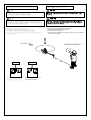
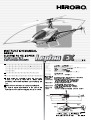
レプトン
組立前に必ずこの説明書を最後まで、よくお読みにな
り、正しくお使い下さい。特に、「組立を始める前
に必ずお読み下さい」は、組立前及び飛行前に必ず読
んで下さい。
この説明書は、大切にお手元に保管して下さい。
製品改良のため、予告なく仕様を変更する場合があります。
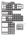
主要諸元
>
? 全備重量
ギヤ比
無線機
適合モーター
適合バッテリー
適合スピード
コントローラー
( ( ( , 約+**(-セル.-/01)**"使用時)
, 12)..-(-セル)1+..-(1セル)
, ヘリ用プロポセット(PCM方式推奨)小型サーボ-個3ジャイロ(別売)
, 4$5アウターローターモーター16,*7,/2*
(0/2* 最大電流-8",+*9)
, 4$5リポバッテリー-/0 1)** "
(リチウムポリマーバッテリー1)** "-セルまたは1セル)
, 4$5 $9(+*" $(
(1セル〜-セル対応 最大+*" $(付)
, ": +** ;< - . -/ 0 1)** "=
, 12)..- ;- = 1+..- ;1 =
, '
;' ( ! ;'(!= = ;9 =
, 4$5 16,*7,/2*
;0 /2* : -8 ",+* =
, 4$5 4 -/ 0 1)** "
;4 1)** " - 1 =
, 4$5 $9(+*" $(
;1 - : +* " $(=
--
288
+*
)/
216
(
!"#$ % &"'"%
)**+
%**
目
次
1.
1. 組立を始める前に必ずお読み下さい .................................. 1
Read before assembly ............................................................... 1
・ネジの種類とサイズの見方 ............................................... 9
· Screws and measurements ...................................................... 9
・キット以外に必要なもの ................................................... 10
· Necessary items not included in this kit ................................ 10
2. 組立編 ....................................................................................... 12
2.
Assembly ................................................................................... 12
3. フライト編 ............................................................................... 44
3.
Flight ......................................................................................... 44
4. メンテナンス編 ....................................................................... 54
4.
Maintenance .............................................................................. 54
5.
5.
Repair Parts .............................................................................. 58
補修パーツについて ............................................................... 58
パーツリスト ........................................................................... 59
Parts list ..................................................................................... 59
データシート ........................................................................... 71
Data sheet .................................................................................. 71
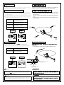
) 組立を始める前に必ずお読み下さい
! 組立を始める前に安全のために必ず
お守り下さい。
このたびは、ヒロボー製品をお買上げいただき、ありがとうござい
ます。
安全にお使いいただくために、飛行前にこの取扱説明書を最後まで
よくお読みください。
飛行上の注意事項、本機の能力、飛行方法などを十分にご理解のう
え正しく、安全にルールやマナーを守って飛行くださるようお願いい
たします。
『シンボルとシグナル用語』の意味について
%#&" 注意文の頭部に表示の「シンボルとシグナル用語」の意味を説明し
ます。
なお、
注意 に記載した事項でも、状況によっては重大な結果
に結付く可能性があります。
警告
誤った取扱をしたときに、死亡や重傷等の重大な
結果に結び付く可能性が大きいもの。
!"#"$
注意
誤った取扱をしたときに、 状況によっては重大な
結果に結び付く可能性があるもの。
%#&"
禁止
&!'#("
絶対に行わないでください。
!"# $ % &
(注):製品の組立、操作、メンテナンスに関する重要なご注意。
' ( )
& * ( + , & !$ &
- . 1. 組立てる前に説明書を良く読んで、おおよその構造及び組立手順を
理解してから組立に入ってください。
2. 組立てる前に、部品の数・内容をお確かめください。パック開封の
後は、部品の交換、返品等については応じかねます。万一部品の不
足・不良があった場合には、お手数ですが、愛用者カードに販売店
の印をもらい、ヒロボー株式会社・営業部まで、部品名と内容を明
記の上ご連絡ください。
1
無線操縦模型の安全について
警告
飛行の前に
1. 可能な限り、飛行場を清掃してください。
◆ 小石、ガラス、くぎ、針金、ひも、浮遊物等の異物を飛行場から
取除いてください。
2. 周囲の状況を考慮してください。
◆ 強風、雨のとき、及び夜間は飛行させないでください。
◆ 人が多い場所では飛行させないでください。
◆ 家、学校、病院などの近くでは飛行させないでください。
◆ 道路、線路、電線などの近くでは飛行させないでください。
◆ 同じ周波数の無線操縦模型が近くにいる時は飛行させないでくだ
さい。
3. 次のような人、または状況下では飛行させないでください。
◆ 子供。
◆ 生理中、妊娠中の人。
◆ 疲れている時、病気の時、酔っている時。
◆ 薬物の影響、その他の理由で正常な操作ができない人。
◆ 初心者の方や、他人の機材を借りる場合、あらかじめ模型を良く
知っている人から安全指導を受けてから始めてください。
4. 無理して使用しないでください。
◆ 機能に適さない改造や加工をしないでください。
◆ 使用限界が示されている物は、必ずその範囲で使用してください。
◆ 空中撮影や農薬散布には使用しないでください。
5. きちんとした服装ではじめてください。
◆ 長そで、長ズボンを着用してください。
◆ 宝石や、物に引っ掛かりやすいものは、身につけないでください。
◆ 長い髪は、肩までの長さに結わえてください。
◆ 足下保護のため、必ず靴を着用してください。
◆ 高温部に触る場合等は、必要に応じて手袋をしてください。
6. ドライバーやレンチ等の工具は取外してください。
◆ 始動する前に組立、取付、整備等に用いた工具類が取外してある
ことを確認してください。
7. 各部の点検をしてください。
◆ 始動前に、各部品に損傷がないか十分点検し、 正常に作動する
か、また所定の機能を発揮するか確認してください。
◆ 可動部分の位置調整、及び各部のボルト、ナットの締付状態、部
品の損傷、取付状態、その他飛行に影響を及ぼす全ての箇所に異
常がないか確認してください。
◆ 無線機器の電源電圧(電池の量 )は十分か確認してください。
◆ 損傷した部品、その他部品交換や修理は、説明書の指示に従って
ください。説明書に指示されていない場合は、お買上げ販売店、
またはヒロボー(株)営業本部エンジニアリングサービスで修理を
行なってください。
◆ 始動前に、必ず各部のネジがゆるんでいないか、指定部への給油
(オイル / グリス)、送・受信機用バッテリーが充分に充電されて
いるかを点検してください。
8. 純正部品を使用してください。
◆ 本説明書、及びヒロボーカタログに記載されている、純正部品以
外のものを使用しないでください。事故やけがの原因となる恐れ
があります。
9. モーターを回さないで、各部の操作方法を練習してください。
◆ モーターを回す前に、各部の操作方法を練習してください。
◆ 操作を充分に修得するまではモーターを回さないでください。
◆ 機械の動きに異常がみられる場合もモーターを回さないでく
ださい。
2
1. Clear as much debris from the airfield as possible.
Clear away pebbles, glass, nails, wire, rope, floating objects, or other trash from
the airfield.
2. Consider the circumstances of the surrounding area.
Do not fly in strong winds, rain, or at night.
Do not fly in a crowded area.
Do not fly near homes, schools, or hospitals.
Do not fly near roads, railways, or power lines.
Do not fly near another radio controlled unit that uses the same frequency.
3. This unit must not be operated by:
Children.
Menstruating or pregnant women.
Tired, sick, or inebriated individuals.
Individuals under the influence of drugs or for some other reason incapable of
operating the unit normally.
Beginners or individuals operating a borrowed unit should proceed only after
having received safety instructions from someone familiar with the model.
4. Do not use the unit improperly.
Do not perform any remodeling or configuration unsuitable for the unit’s
functions.
Make sure to use within the range of the limitations indicated for the unit.
Do not use for aerial photography or crop dusting.
5. Wear appropriate clothing.
Wear a long-sleeve top and trousers.
Do not wear jewelry or objects that may get easily entangled.
Long hair should be bound to shoulder length.
Wear shoes for solid footing.
Wear gloves should it become necessary to touch hot components.
6. Put away screwdrivers, wrenches, or other tools.
Before starting the engine, check that any tools used in the assembly, installation,
or maintenance of the unit have been put away.
7. Inspect each part.
Before starting the engine, check for any damaged parts and make sure that the
unit operates normally with all its functions in order.
Adjust the positioning of moveable parts and check that all nuts and bolts are
fastened, that there are no damaged or improperly installed parts, and that there
are no abnormalities that would adversely affect the flight of the unit.
Check that the power supply voltage (charge of the batteries) in the remote control
is sufficient.
The exchange or repair of damaged parts should be performed according to the
instruction manual. In the event that the desired operation is not indicated in the
manual, ask for repair service at the store from where you purchased the product
or at the engineering services section of Hirobo’s Sales Department.
Before starting the engine, make sure that there are no loose screws, that all
specified locations are properly lubricated with grease or oil, and that the
transmitter and receiver batteries are properly charged.
8. Use genuine parts.
To reduce the risk of accidents and injuries, do not use parts other than those
shown in this instruction manual or in Hirobo catalogs.
9. With the motor off, practice how to operate each part.
Before starting the motor, practice how to operate each part.
Do not start the motor before having acquired sufficient handling skill.
Do not start the motor in the event that any abnormalities are noticed in the
movement of the mechanisms.
警告
飛行中は
1. Do not operate in an awkward posture.
Do not operate seated or lying down.
Because slopes are slippery, exercise caution so as to not loose your
footing.
2. Turn the power off and remove the battery in the following cases.
When adjusting the unit’s body or the transmitter.
When replacing accessories or parts.
When the body of the unit is out of alignment or when abnormal noises
or vibrations occur.
Whenever some kind of danger is anticipated.
3. When turning the power on, observe the following cautions.
Check that there are no people, animals, or obstructions in the surrounding
area.
Hold the unit securely.
Check that the transmitter’s throttle stick is at the lowest position.
1. 無理な姿勢で操縦しないでください。
◆ 寝転んだり、座り込んだりした姿勢で操縦しないでください。
◆ 傾斜地は、滑りやすいので足下に十分注意してください。
2. 次の場合は、電源スイッチを切ってバッテリーを取外してください。
◆ 機体の調整および、送信機の調整を行なうとき。
◆ 付属品および部品を交換するとき。
◆ 機体の調子が悪かったり、異常音や異常振動を発生したとき。
◆ その他危険が予想されるとき。
3. 電源スイッチを入れるときは、次のことに注意してください。
◆ 周囲に人、動物、障害物がないか十分に確認してから始動して
ください。
◆ しっかりと機体を固定または保持してください。
◆ 送信機のスロットルのスティック位置が、最スローの位置にあ
ることを確認してください。
4. 怪我の恐れがありますので回転部分に手や物を入れないでください。
5. 飛行はゆとりとマナーを守ってお楽しみください。
◆ 一度に長時間の操縦や、連続して長時間の操縦は、疲労により
判断力を鈍らせ、思わぬ事故の原因となりますので、適当に休
憩を取るようにしてください。
◆ 操縦しているときは、あまり機体に近づかないでください。
◆ 本人の技量にあった飛行をしてください。無理な飛行は思わぬ
事故や怪我につながります。
6. 飛行直後は、モーターやスピードコントローラーは高温になって
おります。火傷防止のためモーターやスピードコントローラーに
触れないようにしてください。
4. To reduce the risk of injury, do not insert hands or objects in rotating parts.
5. Enjoy the flight while observing safety rules and manners.
Fatigue brought upon by continuous operation for long periods at a time
may result in impaired judgment or accidents. Be sure to take sufficient
rests.
When operating, do not get too close to the unit.
Operate the unit within the limits of your ability. Operating the unit
improperly increases the risk of accidents or injury.
6. The motor and speed controller become extremely hot immediately after flight.
To avoid burns, do not touch them.
飛行後は
1. 注意深く点検をしてください。
◆ すぐに各部の点検を行ない、ネジのゆるみや脱落があれば必ず
補修してください。
◆ 油、よごれ、水滴等はすぐに拭き取ってください。
◆ 長時間保管する場合にはバッテリーを取外してください。
◆ 注油や部品の交換は、説明書に従ってください。
2. きちんと保管してください。
◆ 乾燥した場所で、幼児の手の届かないところに保管してください。
3. 修理は、お買上げの販売店、またはヒロボー(株)営業本部エンジニ
アリングサービスにお申し付けください。
◆ 修理の知識のない方や専用工具を持っていない方が修理をすると、
十分な性能を発揮しないだけでなく、事故や怪我の原因となり
ます。
◆ 修理、調整をするときは、バッテリーを取外してください。
◆ 損傷、故障箇所がある場合には、修理してから保管してください。
この場合、部品は、指定の純正部品を必ず使用してください。
◆ 本体及び周辺機器の加工や改造は、本来の性能を発揮できなく
なる場合がありますので行なわないでください。
◆ 保管時や輸送時は、破損や怪我を防ぐため、機体をしっかりと
固定してください。
1. Conduct a thorough inspection.
Immediately inspect each part and retighten or replace any screws that
may have become loose or fallen out.
Wipe away any oil, dirt, or water.
If storing for an extended period of time, remove the battery.
Lubricate or replace parts according to the instruction manual.
2. Store the unit properly.
Store in a dry place out of the reach of children.
3. Inquire about repairs at the store from where you purchased the product or
at the engineering services section of Hirobo’s Sales Department.
Individuals lacking proper knowledge or tools necessary for repairs may
not only impair the performance of the unit but may also increase the
risk of accidents or injury.
Remove the battery before performing any repairs or adjustments.
Repair all damaged parts before storage. Make sure to use only
designated, genuine parts.
Do not perform any remodeling or reconfiguration of the unit’s body or
peripheral equipment. Doing so may impair the unit’s performance.
When storing or transporting the unit, secure it firmly so as to prevent
damage or injury.
3
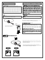
無線操縦ヘリコプターを安全に
お取扱いいただくために
In addition to the standard precautions previously mentioned regarding radio
先に、無線操縦模型として共通の注意事項を述べましたが、ヘリコプ
ターの場合、さらに次に述べる注意事項を守ってください。
警告
controlled models, please observe also the following precautionary items which
are specific to helicopters.
実機の場合、飛行前には厳しい点検が義務付けられています。無線操
For real aircraft, strict pre-flight inspections are mandatory. The radio
縦(R/C)ヘリコプターは小型で手軽に飛行させることができますが、
空を飛ぶことは実機と何ら変わりがありません。万一、人や車などに
controlled helicopter when in flight is essentially no different from a real aircraft
even though it is small and can be flown easily. It may be a great nuisance to
ぶつかれば、大けがや破損につながり、多大な迷惑を与えます。
飛行中の事故は操縦者が責任者扱いされる場合がありますので、必ず
others and, should it strike a person or vehicle, may cause severe injury or
damage. The operator of a radio controlled unit may be held liable for accidents
ラジコン保険に加入してください。詳しくは本機をお買い求めになっ
occurring during flight. For this reason, inquire at the store of purchase about
special insurance that may be taken out for radio controlled devices.
た販売店へお問合せください。
飛行の前や異常が発生した時には、必ず点検をしてください。飛行中
Make sure to inspect the unit thoroughly before flight and in the case of any
に、ローターブレードで地面をたたいた場合、何も損傷がないようで
も、各部に微細な亀裂やゆるみが発生していることがあります。その
abnormality. If the rotor blades should strike the ground during flight, there
may be tiny cracks or loosening in various places even though there may not be
ままで飛行していると、ローターの亀裂が大きくなり、毎分2600回前
後の高速回転をしているローターの内部からウエイトが飛び出したり、
any visible damage. If flown in this condition, the cracks may increase in size
and cause severe accidents such as the weight flying off from the rotor’s
ローターがブレードホルダーから抜けたりする大事故になります。
interior or the rotor itself, which spins at a speed of 2600 rpm, may fly off from
the blade holder.
少しでも疑わしい状態が発生したら、すぐに部品交換をしてください。
部品は必ず純正部品を使用してください。
If in doubt about the condition of any part, replace it immediately using only
genuine parts.
フライト前の始業点検
1.
1. 初心者の方は、指導できる方から安全及び技術指導を受けてくだ
さい。独学は非常に危険です。
2. 各部のナットやボルトにゆるみ、脱落がないか確認してください。
2.
3.
4.
5.
3. リンケージのロッドやアジャスターにガタやゆるみがないか確認
してください。
4. モーターやギヤのボルトにゆるみがないか確認してください。
5. ローターブレードに傷や亀裂がないか、ブレードホルダー周辺は
6.
7.
入念に確認してください。
6. ローターブレードのウエイトは安全に固定されているか確認して
ください。
7. 送信機、受信機のバッテリー容量は十分か確認してください。
8.
9.
Beginners should have safety and technical guidance from an experienced
individual. Teaching yourself is extremely dangerous.
Check that there are no missing or loose nuts or bolts.
Check that there is no rattle or loosening in the linkage rods or adjusters.
Check that there are no loose bolts in the motor or gear.
Carefully check that the rotor blades are not damaged or cracked, especially
in the vicinity of the blade holder.
Check that the rotor blade weight is safely fastened.
Check that the batteries for the transmitter and receiver are sufficiently
charged.
Check the reach of the radio waves.
Check that the servos operate smoothly. Their malfunction may cause a
loss of control and increase the risk of danger.
10. Check that the gyro is operating properly and, especially, in the right
direction while starting the engine.
11. Check the tension of the tail rotor belt drive.
12. Check that each part of the unit’s body is sufficiently lubricated.
8. 電波の届く距離を確認してください。
9. 全てのサーボがスムーズに動作するか確認してください。誤動作
やムリな動作は操縦不能の原因となり、たいへん危険です。
10. ジャイロは正しく作動するか確認してください。特に初期状態に
おいては動作方向を確認してください。
11. テールローターの駆動ベルトのテンションは適当か確認してくだ
さい。
12. 機体各部の潤滑油の給油を確認してください。
4
警告
フライト中の安全確認
1. Check that there are no objects in the surrounding area that may get
entangled or struck by the unit during flight.
2. Check that there are no other operators in the surrounding area using the
same frequency, set the transmitter’s throttle stick at the lowest position,
and then turn on first the transmitter and then the receiver.
3. When turning the power on, make sure to hold the rotor head firmly by
hand to prevent it from rotating.
4. Because the motor and speed controller become hot during flight,
exercise caution to prevent burns.
5. When taking off, the unit should be positioned 15 meters or more away
from the operator. Be aware of the conditions of the surrounding area
and check that there are no other people or dangerous obstacles.
6. Just before take off, adjust the tracking (each rotor’s track). Even when
checking the tracking, do not get nearer than 5 meters from the unit.
7. In the event that abnormal noises or vibrations should occur during the
flight, land the unit immediately, remove the battery connector, and
check the cause of the problem.
8. Because operating the unit improperly or recklessly may cause accidents
or injury, observe all safety rules and manners and enjoy operating the
unit safely and responsibly.
1. 飛行するときは周辺に当たるものや、巻き込まれそうなものがな
いか確認してください。
2. 周囲に同じ周波数の使用者がいないことを確認して、送信機のス
ロットルスティックを最スローにして、送信機→受信機の順番に
スイッチを入れてください。
3. 電源スイッチを入れるときは、必ずローターヘッドをしっかりと
回転しないように手で押さえてください。
4. 飛行中は、モーター及びスピードコントローラー部が高温になり
ますので、火傷に注意してください。
5. 飛行をはじめるヘリコプターの位置は、操縦者より15m以上離れ
た場所で行なってください。また、周囲の状況を十分把握し、飛
行場内に他の人や危険物、障害物がないか確認してください。
6. 機体が浮かび上がる直前に、トラッキング(各ローターの軌跡)調
整を行なってください。トラッキングを確認する場合でも、機体
から5m以内に近づかないでください。
7. 飛行中に異常な振動や、異常な音が発生した場合、すぐに着陸させ、
バッテリーのコネクターを抜いて原因を確認してください。
8. 無理な飛行や無謀な操縦は、事故や怪我の原因となりますので、
ルールやマナーを守り、安全に責任をもってお楽しみください。
フライト後の安全点検
1. Immediately inspect each part after every flight. Be sure to replace or
retighten missing or loose screws and replace any damaged parts.
2. Wipe away any oil or dirt.
3. If the unit will not be used for a long period of time, remove the battery.
1. 飛行が終わったら、すぐに各部の点検を行ってください。ネジの
ゆるみや脱落があれば、必ず補修してください。各部に傷や破損
があれば、交換してください。
2. 油汚れ等をきれいに拭き取ってください。
3. 長時間(期間)飛行させない場合は、バッテリーを取外してください。
保管場所
1. 直射日光のあたる場所、高温になる場所(車内等)に放置しないで
ください。
必ず風通しのよい日陰で保管してください。
2. バッテリーのコネクターをスピードコントローラーに繋いだまま
ヘリコプターを保管しないでください。
1. Do not store in an area exposed to direct sunlight or where temperatures
may rise (i.e. in a car). Instead, store it in a shaded, well ventilated area.
2. Do not store the unit with the battery connector connected to the speed
controller.
5
For the safe operation of electric models
電動模型の安全について
警告
WARNING
Before using the unit
ご使用の前に
Never leave equipment such as the transmitter, dry battery, battery, charger
or flying unit in a location that can be accessed by the inquisitive hands of
infants or children.
They can accidentally activate operation, or put the battery or small parts in
their mouth; any of such actions could result in injury or damage caused by
chemical substance.
Never disassemble or attempt to modify anything other that what is
specified by this manual.
Doing so could cause electric shock, an injury, equipment breakdown or a
subsequent fire.
Never store the transmitter, battery, charger, or flying unit in the following
places. Storing such equipment in these places could cause shape distortion,
breakdown and
subsequent injury or fire as a direct result of equipment breakdown.
・ Hot places that exceed 40 °C or cold places that fall below -10 °C
・ Places exposed to direct sunlight
・ Places with high humidity, vibration, or lots of dust
・ Places with moisture or steam or where exposed to a source of heat
Never fly this product in the following places.
1. Places where there is moisture
This product does not have any protection against grit or water. If grit
(sand dirt, etc.) or water were to penetrate the inner part of the unit, it
would cause faulty operation, a crash or breakdown.
2. Close to other flying fields for radio controlled aircraft (3 km radius) or
close to high voltage lines or communications installations
This will cause a crash due to signal interference, if a crash occurs due to
breakdown of the flying unit or transmitter, the collision could cause an
injury or some kind of property damage.
Always refrain from flying units that use the same radio frequency at the
same time. The radio signal interference will cause a crash.
* The radio signal interference will still happen when the radio frequency is
the same even if a different modulation type is used (AM, FM, PCM etc).
Always refrain from touching parts that are installed in the flying unit,
namely the motor, pinion gears and speed controller during use or directly
after use.
These parts heat up to high temperatures and can cause burns.
送信機、乾電池、バッテリー、充電器、機体等を幼児や子供の手の
届くところに放置しないでください。
さわって作動させたり、電池をなめたり、小さな部品を口にいれた
りすると、ケガや化学物質による被害を受ける可能性があります。
本書で指定した箇所以外の分解、改造を行わないでください。
感電、ケガ、機器の故障やそれに伴う火災の原因になります。
送信機、バッテリー、充電器、機体を次のような場所に保管しない
でください。
このような場所に保管すると変形や故障、機器の故障に伴う火事や
ケガの原因となります。
・40℃以上になる暑いところ、-10℃以下になる寒いところ。
・直射日光があたるところ。
・湿気、振動、ほこりの多いところ。
・水分や蒸気、熱が当たるところ。
次のような場所では飛行させないでください。
1. 水気のある場所
防砂・防水対策が行われていません。装置内部に砂や水が入ると
誤動作して墜落したり、故障の原因になります。
2. 他のラジコン飛行場の近く(3km 程度以内)や高圧線・通信施設の
近く電波の混信などにより墜落したり、万一プロポや機体の故障
により墜落した場合、衝突によるケガや物損の原因になります。
同じ周波数の機体を同時に飛行させないでください。電波が混信し
て墜落します。
※変調方式(AM,FM,PCM 方式など)が違っていても周波数が同じ場合
は混信します。
使用中、使用直後には機体に搭載されているモーター、ピニオンギヤ、
スピードコントローラーには触れないでください。
高温になっているためヤケドします。
注意
CAUTION
Never fly in a place cluttered with obstacles (near buildings, people, pets,
etc.).
Never disassemble or attempt to modify the product. It will cause a
breakdown.
Never put hands or face close to rotating parts. Doing so creates the risk of
unexpected injury.
To avoid such risk, never operate this product while sitting on the floor or on
a chair. Operate this product in a posture that allows you to quickly get out
of the way if necessary.
Always switch off both the flying unit and transmitter when leaving the
transmitter unattended.
If the power switch is left on, it is possible that unintended stick operation
causes accidents.
Never allow young children to use this product due to the risk of accidents
or injuries caused by contact with rotating parts, short circuits, or electric
shocks, etc.
Always use this product in a way that is proper and safe to maintain its
performance. To do this you must read this instruction manual thoroughly.
This product is a precision machine that can easily be broken if dropped or
used incorrectly.
Never use parts that are damaged or have altered shape in this product to
ensure safe practice.
Always pay attention to the fact that much functionality is required of this
product's parts andparts include small items, sharp items and items made
from metal. Prevent any possibility of a small child putting these parts in
their mouth or getting injured by these parts. If a child swallows a part, seek
urgent medical advice. Always discard the packaging of the parts in a place
out of reach of children.
The cost, specifications and dimensions of products can change without
prior notification.
混雑した所(建物、
人、
ペットなどの近く)では飛ばさないでください。
分解したり改造したりしないでください。故障の原因となります。
回転部分には手や顔を近づけないでください。思わぬケガの恐れがあります。
危険回避のため、
本製品をイスや床に座った姿勢で操作しないでください。
万が一のときに素早く移動できるように立って操作しましょう。
送信機から手を放す時は必ず機体と送信機のスイッチをOFF にしてください。
電源スイッチONのまま、
放置すると不用意なスティック操作による事故の原因
となる恐れがあります。
回転部分や電気による事故の危険がありますので、小さなお子様には絶対
に使用させないでください。
本製品は精密機器ですので誤使用や落下などにより壊れる恐れがあります。
性能維持のため、
この取扱説明書をよく読み、
正しく安全にお使いください。
安全のため、
破損、
変形した部品は、
使用しないでください。
部品は機能上の必要性から、
小さいもの、
鋭い形状のもの、
金属でできたもの
を使用している場合がありますので、
小さなお子様が口に入れたりケガなどし
ないように十分注意してください。万一、
お子様が飲み込んだ場合は、
ただち
に医師と相談してください。また、部品が入っていた袋類も手の届かない所
に捨ててください。
商品の価格、
仕様、
形状等は予告なく変更する場合があります。
6
警告
バッテリー、充電器の取扱いについて
リチウムポリマーバッテリーは過充電、過放電、その他誤った取扱
いをすると、機器の故障だけでなく、破裂、異常発熱、発火などの
可能性があり、大変危険です。
下記の事項を必ず守り、正しく安全に使用してください。誤って使
用された結果による事故、その他につきましては、当社では一切の
責任を負いません。
If lithium polymer batteries are overcharged, over discharged or
mistreated in any other way, not only could it cause the equipment to
malfunction, it also could cause the battery to burst, get abnormally
hot or ignite, which is very dangerous.
Always adhere to the following instructions and use the lithium
polymer batteries properly and safely. Hirobo will in no way be held
liable for accidents or other incidents occurring as a result of
incorrect use of the batteries.
火の中に投入したり・加熱したりしないでください。また、分解
したり改造したりしないでください。破裂、異常発熱、発火など
によりケガ、ヤケドなどをします。
高温になった車の中や炎天下、60℃以上のところに放置しないで
ください。
強い衝撃を与えたり落としたりしないでください。
水などでぬらさないでください。
プラス(+)とマイナス(−)の端子をネックレスやクリップなどの
金属類でショート(短絡)させないでください。
充電をしないときは充電器のプラグをコンセントから外して保管
してください。
過放電させるとバッテリーが使用できなくなりますので飛行後は
速やかに充電して保存してください。
バッテリーの使用中や充電中、保管時に異臭を感じたり、発熱、
変形、変色したり、その他今までと異なることに気が付いた時に
は、直ちにコネクターを外し、使用をやめてください。
一度異常の見られたバッテリーは使用せず、新しいバッテリーと
交換してください。
Never throw the batteries into a fire or heat them up in any way. Moreover,
never disassemble or attempt to modify the battery. Such actions could
cause the batteries to burst, get abnormally hot or ignite, which could cause
injuries such as burns.
Never leave the batteries inside a car on a hot day where they can get very
hot, or in places where the temperature exceeds 60°C.
Never hit the batteries or drop them.
Never allow the batteries to get wet.
Never short the batteries by connecting the positive (+) and negative (-)
terminals with a metal object such as a necklace or paper clip.
Always ensure the charger is kept with its plug removed from the power
outlet at all times other than when charging.
Always recharge the batteries and store them after flying because the
batteries can no longer be used if they have been over discharged.
If during battery use, battery charging or during battery storage, a strange
smell is noticed, or a battery begins to get hot, become misshapen or
discolored, or you notice anything else that is different about the battery,
disconnect the connector immediately and discontinue battery use.
Never use a battery that has shown any sign of abnormal performance. In
such a case always replace the battery with a new one.
●バッテリーのリサイクルについて
使用できなくなったリチウムポリマーバッテリーは捨てないで、充電式電池リサイクル協力店に
ある充電式電池リサイクルBOXに入れてください。
リチウムポリマーバッテリーには、主な材料としてリチウムやコバルトなど希少な資源が使われ
ています。限りあるこれらの資源の有効活用のため、ぜひリサイクルにご協力ください。
(小形充電式電池のリサイクルは、2001年4月より施行された資源有効利用促進法に基づき、有限
責任中間法人JBRCにより行われています。)
有限責任中間法人JBRCのホームページでお近くのリサイクル協力店を検索する事が出来ます。
http://www.jbrc.com/
●Battery recycling
Do not throw the lithium polymer battery that can no longer be used away, but put it in the rechargeable
battery recycle box located at stores assisting with battery recycling.
The lithium polymer battery contains scarce resources such as lithium and cobalt as main materials.
For the effective utilization of these limited resources, we ask for your cooperation with recycling.
(Recycling of small rechargeable batteries is carried out by the Japan Portable Rechargeable Battery
Recycling Center (JBRC) in accordance with the Law for the Promotion of Utilization of Recyclable
Resources which was enacted in April 2001.)
Visit the JBRC Website to find your nearest store assisting with battery recycling.
http://www.jbrc.com/
7
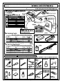
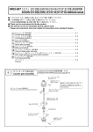
! この説明書の見方
組立前の注意
1. 組立てる前に説明書を良く読んで、おおよその構造及び組立手順
を理解してから組立に入ってください。正しい組立を行わないと、
本来の性能を発揮できなくなるばかりでなく、大変危険です。
2. 組立てる前に、部品の数 ・ 内容をお確かめください。パック開封
の後は、部品の交換、返品等については応じかねます。万一部品
の不足 ・ 不良があった場合には、お手数ですが、愛用者カードに
販売店の印をもらい、ヒロボー株式会社 ・ 営業本部まで、部品名
と内容を明記の上ご連絡ください。
1. Before assembly, read the instruction manual thoroughly and familiarize
yourself with the unit’s structure and assembly procedures. Failure to
assemble the unit properly may not only result in impaired performance
but may also increase the risk of danger.
2. Before assembly, check the quantity of parts and their descriptions. After
the packaging has been opened, parts cannot be exchanged or returned. In
the event of any missing or defective parts, have the store from where you
purchased the product stamp your user’s card and send it with the name
and description of the part(s) to Hirobo’s Sales Department.
①
のマークがある箇所は、ホビータイト(ネジロック剤)を
使用してください。
① Apply Hobby Tight (thread locking agent) at each location indicated with
② 説明書の左欄を参考にして、小物類の数量チェックを行ってくだ
さい。
② In the instruction manual, refer to the column on the left-hand side to check
the type and quantity of small parts.
%&
.
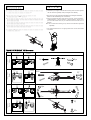
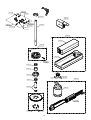
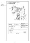
スワッシュプレートの組立
$
M2X6CS
EX ø5ボール台付
EX ø5 ball with stand
M2X6CS
M2X6CS ........................... 7
M2X12CS D=3.3
EX ø5ボール
EX ø5 ball
M2X12CS D=3.3 ................ 1
EX ø5ボール ...................... 3
EX ø5 ball
1
EX ø5ボール台付 ............... 4
EX ø5 ball with stand
EX ø5ボール台付
EX ø5 ball with stand
ø3.5ラジアスピン
ø3.5 radius pin
EX ø5ボール
EX ø5 ball
ø3.5ラジアスピン............... 1
ø3.5 radius pin
M2X6CS
2
M2X6CS
EX ø5ボール
EX ø5 ball
EX ø5ボール台付
EX ø5 ball with stand
小物部品の名前、原寸図、使用数
# "
警告
!
!"
本製品の改造、又、弊社以外の部品交換について、十分なテストを
行っていませんので、事故発生の可能性もあります。その場合、一
切の責任を負いかねますのでご了承ください。
8
ネジの種類とサイズの見方
How to read part types and sizes
本説明書の文中に記載している記号は、次の約束になっています。
● 単位はミリメートルです。以下、文中で長さなどに表示されてい
る単位はミリメートルです。
The symbols shown in this instruction manual are shown as below:
The unit of measurement is the millimeter. The lengths, etc. shown
in the following are indicated in millimeters.
¿5ボール
¿5 ball
セットスクリュー
ナベ頭ビス
Set screw
Pan-head screw
4mm
12mm
M3X12PH
3mm
M3X4SS
3mm
¿5ボール
¿5 ball
段付ビス
キャップスクリュー
メタル
Shoulder screw
Cap screw
Bushing
M2X4.5段付
M2X4.5
shoulder screw
3mm
タッピングビス1種
ナット
Nut
Tapping screw 1
カラー3X6X7
3mm
Eリング
E-ring
Collar 3X6X7
タッピングビス2種
6mm
¿6 Eリング
¿6 e-ring
ナイロンナット
Tapping screw 2
6mm
5.5mm
M3 ナット
M3 nut
3mm
7mm
2mm
10mm
M3X10TS-1
3mm
4.5mm
8mm
M3X8CS
5mm
カラー
3mm
Nylon nut
Collar
5mm
8mm
M3X8TS-2
5.5mm
ミゾ付
3mm
Grooved
皿ビス
M3 ナイロンナット
M3 nylon nut
カラー5X8X5.5
Collar 5X8X5.5
フラットワッシャー
Countersunk screw
スラストベアリング
3mm
Flat washer
Thrust bearing
12mm
M3X12皿ビス
M3X12
countersunk screw
4.5mm
9mm
Brg. ¿6X¿12X4.5H
12mm
4mm
皿タッピングビス
ベアリング
Countersunk tapping
screw
M3X10皿TS-1
M3X10
countersunk TS-1
6mm
1mm
FW 3X9X1T
3mm
8mm
Bearing
10mm
3mm
4mm
Brg. ¿4X¿8X4ZZ
Brg. ¿4X¿8X2.5F ZZ
4mm
8mm
2.5mm
8mm
タッピングビスは、部品にネジを切りながらしめつけるビスです。しめこ
みが固い場合がありますが、部品が確実に固定されるまでしめこんでくだ
さい。ただし、しめすぎるとネジがきかなくなりますので、部品が変形す
るまでしめないでください。
Tapping screws cut threads in the holes of the parts. When screws are difficult to
tighten, fasten the screw until the part is properly set. However, do not over-tighten
the screw to the point of stripping the threads or warping the part.
ボタンボルト
Button bolt
M3X8ボタンボルト
M3X8 button bolt
3mm
Correct
Wrong
しめすぎ
Over-tightened.
9
8mm
ネジがきかない
Stripped threads.
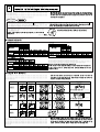
フライトするためにキット以外に必要なもの
(別売)
当機を楽しむためには、以下のものが必要です。(別売) 税込価格(税抜価格) ! " #
■$.3対応プロポセット(&23デュアルコンバージョン方式推奨)
受信機(&23デュアルコンバージョン方式推奨)
(' & 2 3 &23 ' "" #
$.3 " !"" " & 2 3 &23 ' "" #
$.3 サーボ(エルロンチャンネル)
$.3 ' $.3 サーボ(エレベーターチャンネル)
$.3 ' ' 使用可能サーボ ※
+年月現在
$' / 7 / +
$.3 * * サーボ用
ラダー用
; $.3 * * '
; $ (推奨)("" $+ (推奨)("" $ (推奨)("" $+ (推奨)("" フタバ
$ ; $
$
スイッチ
$
$5
0$ +(推奨)("" 89$ (推奨)("" 0$
+
0$
+
<(
89$ 0$ +
89$ $(3 (>(推奨)("" サンワ $0= ,+
$5
$0= ,+
注意 "
フィルター付延長コード
はジャイロと受信機の間
に入れてください。
; 4 0 <
ラダーサーボ
$.3 サーボ(ピッチチャンネル) ( '
$.3 ' 送信機
"
フィルター付
延長コード
9
5
7
ジャイロ
:
双葉社製受信機 ! !"#
$%&'(は使用できません。
)
*
! !"# $%&'(
+
!
■バッテリー、充電器セット
$ 7 !
3 コード
!
!
!
4 品
名
入数
"#$ パワーパック%&'
"#$ ( %&'
"#$ +チャージャー! セル
"#$ + ! "#$ リポバッテリー ,.*/
"#$ 0 ,.*/
式
4
税込価格
(税抜価格)
円
5 6 )
*)
,)-
,)
*,)1
*2)
$ 7 " 3 4 品
名
入数
!1
"#$ パワーパック7
"#$ ( 7
"#$ アウターローターモーター299,-
"#$ 299,-
!:
"#$ #8:/ %#
!*
組立に必要な工具
式
!
!*
■モーター、スピードコントローラーセット
コード
!
4
!1
税込価格
(税抜価格)
円
5 6 1) 1
-)
*1)*
* )
*,)1
*2)
!:
¥税込価格(税抜価格) +ドライバー 大・小
ラジオペンチ
6! "
6! & 5 '
ホビーオイル
カッターナイフ
2 )7
ハサミ
ピンドライバー
%# ドリル
$
& '
%# 瞬間接着剤
? '
- - (曲面12')
- - + + + % #* % #-* %# 付
(ミニ13)
. % #* % #-* %#
両面テープ
0 ' ネジロック剤
)!
!
ロッドエンドペンチ
ニッパー
( )
8
*+, *
! " #
十字レンチ
2 5
* # * # * ,""
六角レンチ
ピッチゲージ
/ ) ' & !!
# "" "" # "" + "" , * *- あると便利な周辺用具
ロッドエンドドライバー
# (## ( # + ) / #) +.
品
名
" ¥税込価格(税抜価格)9 :( ロッドエンドトリマー
コード
$ RCグラスター
% & #
% ' ( - !
RCアルコールスプレー
% 0)# 1 * - !
RCグリススプレー
% & # - !
RCほこりとばしスプレー
RC防錆潤滑スプレー
% ' )# 7) /
- !
9 :( # (## ( # + ) / #) +.
税込価格
(税抜価格)円
!
$
$
8$
8
8
8
8
8
備
考
#
汚れの除去とつや出しが一度にできるワックス入りクリーナー
' ( )# * + ( # !) * #( ,, ( #(
ゴム及びシリコン部品にも使用出来ます(飲用不可)
)# ) # #. " , , /.
強力エアーでほこりを一発除去
' #/ 2 , ( *# * ! )# # / #(.
たれ落ちないグリス、垂直面にも34!
& # ( #5 . & , #), # 6
さらっとした防錆潤滑剤
' )# ) ( # ( #), #( / #!.
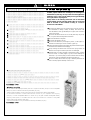
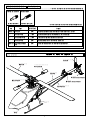
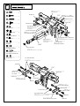
各部の名称
テールブレード
メインブレード
スタビライザーブレード
テールブーム
垂直尾翼
メインローターヘッド
水平尾翼
テールブームブレース
スキッド
Skid
キャビン
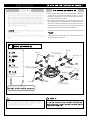
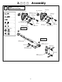
2. 組立編 Assembly
1
SWMレバーの組立
SWM lever assembly
Brg. ø4Xø8X3ZZ
Brg. ø4Xø8X3ZZ
T型レバー
T-type lever
EX ø5ボール台付
EX ø5 ball with stand
M2X6CS ........................... 6
EX ø5ボール
EX ø5 ball
EX ø5ボール
EX ø5 ball
M2X8CS ........................... 3
M3X3SS ........................... 2
C ø4Xø6X2
EX ø5ボール ...................... 6
EX ø5 ball
C ø4Xø6X2
Brg. ø4Xø8X3ZZ
M2X6CS
EX ø5ボール
EX ø5 ball
EX ø5ボール台付
EX ø5 ball with stand
EX ø5ボール台付 ............... 3
EX ø5 ball with stand
M2X8CS
M2X6CS
Brg. ø4Xø8X3ZZ
仮止め
Temporarily set
M3X3SS
Brg. ø4Xø8X3ZZ ................ 4
C ø4Xø6X2 ......................... 2
仮止め
Temporarily set
SWMレバーシャフト
SWM lever shaft
M3X3SS
SWMフロントレバー
SWM front lever
M2X8CS
EX ø5ボール
EX ø5 ball
EX ø5ボール台付
EX ø5 ball with stand
M2X6CS
SWMトルクレバー
SWM torque lever
12
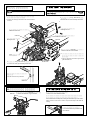
注意
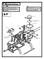
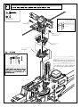
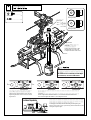
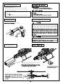
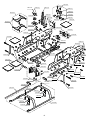
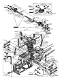
フレームの組立
注意
EX ø5ボール台付
EX ø5 ball with stand
カーボンフレームは、カット、穴開け時に板面
にバリなどが出ていることがありますので、外
周やベアリングホルダー、クロスメンバーの取
付け位置を紙ヤスリで平らにしてください。
EX ø5ボール台付を取付けたレバーを
右側に取付けます。
Mount the lever with the EX ø5 ball with stand
on the right side.
ピボットボルトE
Pivot bolt E
クロスメンバーM3X12.5
Cross member M3X12.5
M2.6X6CS
M2X5CS
バリ
Burrs
M3X12TSトラス-2
M3X12TS truss-2
C ø3Xø7X3.8S
M3X5CS
FW ø3Xø4.5X0.5T
ラジアスステー
Radius stay
M3X10CS
ガイドプーリー
Guide pulley
M2ナイロンナット
M2 nylon nut
プーリーステー
Pulley stay
M2.6X6CS
段のある方を外側に
してください。
Place the stepped side
to face outside.
C ø3Xø4X8.5F
C ø3Xø4.5X3
M2.6X6CS
M3X5CS
クロスメンバーM3X12.5
Cross member M3X12.5
C ø3Xø7X3.8S
ピボットボルトE
Pivot bolt E
ø16 BRGホルダー
ø16 BRG holder
M2.6X6CS
M2X5CS
メインフレーム
Main frame
M3X12TSトラス-2
M3X12TS truss-2
C ø3Xø4X8.5F
M2.6X6CS
M3X3SS
マグネシウムセンターフレーム
Magnesium center frame
M2.6X6CS
メインフレーム
Main frame
EX ø5ボールを取付けたレバーを
左側に取付けます。
Mount the lever with the EX ø5 ball
on the left side.
M2X5CS ............................. 4
M2.6X6CS.......................... 16
注意
M2ナイロンナット
M2 nylon nut
注意
M3X5CS ............................. 2
EX ø5ボール
EX ø5 ball
ボールベアリングのフラ
ンジが外側になるように
組立ててください。
M3X10CS ........................... 2
M3X12TSトラス-2 ............ 4
M3X12TS truss-2
M3X3SS ............................. 2
ピボットボルトE .............. 2
Pivot bolt E
FW ø3Xø4.5X0.5T .............. 1
M2ナイロンナット ........... 2
M2 nylon nut
C ø3Xø4.5X3 ...................... 2
C ø3Xø7X3.8S .................... 4
C ø3Xø4X8.5F .................... 2
13
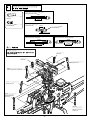
フレームの組立-2
M2.6X6CS ......................... 10
ねじ切り
Threaded hole
M2.6X6TSトラス ............... 8
M2.6X6TS truss
穴
Hole
M2.6X6CS
M3X5CS ............................. 4
M3X20CS ........................... 2
テールブームホルダー
Tail boom holder
SWMサーボマウント
SWM servo mount
仮止め
Temporarily set
M2.6X6CS
C ø3Xø5X11 ....................... 4
M3ナイロンナット薄型 .......... 2
M3 nylon nut thin type
仮止め
Temporarily set
M2.6X6TSトラス
M2.6X6TS truss
ピボットボルトø5X4
Pivot bolt ø5X4
M2.6X6CS
M3X5CS
ボディマウント
Body mount
フロントステー
Front stay
M2.6X6TSトラス
M2.6X6TS truss ピボットボルトø5X4
Pivot bolt ø5X4
仮止め
Temporarily set
M3X20CS
M3X5CS
C ø3Xø5X11
M3ナイロンナット薄型
M3 nylon nut thin type
クロスメンバーM3X26
Cross member M3X26
ボディマウント
Body mount
C ø3Xø5X11
M3X20CS
フロントステー
Front stay
14
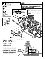
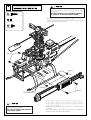
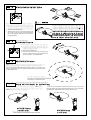
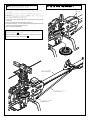
ランディングギヤの取付
すべてのネジを締めた後、レバー
がスムーズに動くか確認してくだ
さい。
スムーズに動かないときはM2ナ
イロンナットやM3X3SSをゆるめ
て、再度締めなおしてください。
After tightening all screws, check
that the lever moves smoothly.
If it does not move smoothly, loosen
the M2 nylon nut or M3X3SS, and
then retighten it.
ジャイロマウント
Gyro mount
M3X8TSトラス-2
M3X8TS truss-2
M3X5CS
クロスメンバーM3X26
M2.6穴付
Cross member M3X26
with M2.6 holes
M3X8TSトラス-2
M3X8TS truss-2
M3X5CS
M2X8CS ............................. 2
M2.6X12CS ........................ 4
M3X5CS .............................. 4
M3X8TSトラス-2............. 12
M3X8TS truss-2
FW ø2.6Xø7.5X0.5Tクロ..... 4
FW ø2.6Xø7.5X0.5T black
M3X8TSトラス-2
M3X8TS truss-2
クロスメンバーM3X26
M2.6穴付
Cross member M3X26
with M2.6 holes
先にスキッドに固定してか
らフレームに取付けると組
立てやすくなります。
It is easier to assemble by first
fixing the cross member to the
skid, and then attaching it to
the frame.
ロッドエンドM2X9 .......... 2
Rod end M2X9
ジャイロマウント
Gyro mount
M2X8CS
ロッドエンドM2X9
Rod end M2X9
M2X8CS
FW ø2.6Xø7.5X0.5Tクロ
FW ø2.6Xø7.5X0.5T black
M2.6X12CS
ロッドエンドM2X9
Rod end M2X9
FW ø2.6Xø7.5X0.5Tクロ
FW ø2.6Xø7.5X0.5T black
M2.6X12CS
アンテナパイプ
Antenna pipe
必要な長さにカットして使用して
ください。
Cut the pipe to the required length.
15
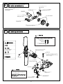
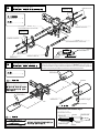
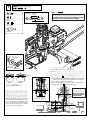
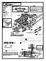
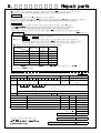
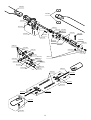
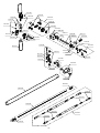
ケース部の組立
M2ナイロンナット
テールプーリー14T
M2 nylon nut
Tail pulley 14T
工場取付済
Already attached prior
タイミングベルト
to shipment.
Timing belt
Brg. ø4Xø8X3FZZ
M2X5CS ........................... 6
M2X5CS
C ø2Xø4X12
M2X18CS ........................... 1
FW ø4Xø6X0.5T ................. 1
注意
工場取付済
Already attached prior
to shipment.
Brg. ø4Xø8X3FZZ
テール軸
Tail shaft
C ø2Xø4X12 ....................... 1
M2ナイロンナット ........... 1
M2 nylon nut
ニードルピン1.5X7.8
Needle pin 1.5X7.8
(テール軸にネジロック剤で
接着してください。)
(Attach the needle pin to the tail
shaft using a thread-locking agent.)
テールピッチレバーステー
Tail pitch lever stay
テールホルダー
Tail holder
M2X18CS
FW ø4Xø6X0.5T
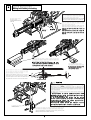
タイミングベルトは、折り曲げたり、キズをつけたりしないでください。
破損の原因になります。
テールBRGプレート
Tail BRG plate
M2X5CS
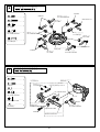
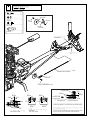
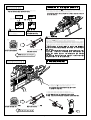
テールハウジング部の組立
M1.7X5TS ........................... 8
M2X6CS ............................. 2
M2X12CS D=3.3 ................ 2
テールハウジング
Tail housing
M2X6CS
EX ø5ボール ....................... 2
EX ø5 ball
EX ø5ボール
EX ø5 ball
Brg. ø3Xø8X4ZZ ................ 4
Brg. ø3Xø8X4ZZ
テールブレードホルダー(A)
Tail blade holder (A)
テールブレードホルダー(B)
Tail blade holder (B)
M2X12CS D=3.3
M2ナイロンナット ........... 2
M2 nylon nut
M2.6ナイロンナット ........ 2
M2.6 nylon nut
M2.6ナイロンナット
M2.6 nylon nut
M1.7X5TS
M2ナイロンナット
M2 nylon nut
テールブレード
Tail blade
16
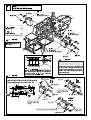
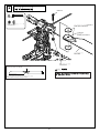
テールピッチプレートの組立
テールピッチプレートAssy工場組立済
Tail pitch plate assembly
(pre-assembled)
テールピッチリンク
Tail pitch link
ニードルピンø1.5X5.8
Needle pin ø1.5X5.8
テールピッチプレート
Tail pitch plate
スライド軸
Slide shaft
ニードルピンø1.5X5.8
Needle pin ø1.5X5.8
Brg. ø6Xø10X3ZZ
テールピッチリンク
Tail pitch link
W型テールピッチプレートボス
W-type tail pitch plate boss
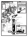
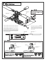
テールハウジング部の取付
注意
シャフトのくぼみに合わせて締め込む。
テールハウジング
Tail housing
M3X3SS
テールプーリーシャフト
Tail pulley shaft
M2X18CS ........................... 1
M3X3SS .............................. 1
テールピッチプレートAssy
Tail pitch plate assembly
ガイドピンM3X6.3 ........... 2
Guide pin M3X6.3
M2X18CS
テールピッチレバーが軽く動く
ところまで締め込みます。
Tighten until the tail pitch lever can
still move slightly.
M2ナイロンナット ........... 1
M2 nylon nut
C ø2Xø4X12 ...................... 1
M3X3SS
ガイドピンM3X6.3
Guide pin M3X6.3
C ø2Xø4X12
注意
テールピッチガイドピンは、テール
ピッチプレートの溝にはまるように
取付けてください。
M2ナイロンナット
M2 nylon nut
ガイドピンM3X6.3
Guide pin M3X6.3
17
テールピッチレバー
Tail pitch lever
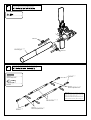
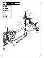
テールブームパイプの取付
M2X5CS ............................. 4
M2X5CS
テールブームパイプ
Tail boom pipe
M2X5CS
テールブームブレース部の組立
ロッドエンド
Rod end
M2X16アジャストロッド ......... 4
M2X16 adjust rod
ロッドエンド ..................... 4
Rod end
M2X16アジャストロッド
M2X16 Adjustment rod
M2X16アジャストロッド、ロッド
エンドは入るところまでしっかり
締め込んでください。
Tighten the M2X16 adjustment rods
and rod ends securely all the way in.
テールブームブレース
Tail boom brace
ロッドエンド
Rod end
M2X16アジャストロッド
M2X16 Adjustment rod
18
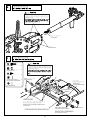
テールブームの取付
注意
テールブームパイプが入りにくいときは、
マイナスドライバー等で隙間を少し広げて
入れて下さい。
タイミングベルト
Timing belt
仮止め
Temporarily set
ラダーサーボの取付
注意
M2.6X10CS ......................... 4
M2.6ナイロンナット ........ 4
M2.6 nylon nut
M2X5CS ............................. 2
FW ø2.6Xø7.5X0.5Tクロ..... 4
FW ø2.6Xø7.5X0.5T black
ラダーコントロールサーボと受信機叉はジ
ャイロアンプの間に、ノイズフィルターを
取付けてください。
M2.6ナイロンナット
M2.6 nylon nut
ラダーサーボ
(ラダーチャンネルへ)
Rudder servo
(To the rudder channel)
FW ø2Xø6X0.4T ................. 2
FW ø2Xø6X0.4T
M2X5CS
ラダーサーボプレート
Rudder servo plate
サーボの大きさに合わせてサーボマウン
トを左右に移動させてください。
Move the servo mount left or right to match
the servo size.
サーボに付属のゴムグロメットを使用します。
Use the rubber grommets included with the servo.
19
FW ø2.6Xø7.5X0.5Tクロ
FW ø2.6Xø7.5X0.5T black
サーボによっては使用しません。
These may not be used depending on
the servo that you select.
M2.6X10CS
SWMサーボの取付
SWM servo installation
12
サーボプレート
注意
サーボ
(エルロンチャンネルへ)
サーボ
(ピッチチャンネルへ)
Caution
サーボの向きに注意
Note the orientation of
the servos.
サーボ
(エレベーターチャンネルへ)
サーボプレート
注意
Caution
使用する送受信機のセット内容や設定でサ
ーボと受信機の接続方法は異なります。
送受信機の説明を参考にしてください。
注意
Caution
The way the servos are connected to the
receiver to vary with the contents and
settings of the transmitter-receiver set.
Please refer to the transmitter-receiver
instruction manual.
SWMレバーとサーボの中心が水平に並ぶ位置で、
仮止めしていたM2.6X6TSトラスを本締めします。
Securely tighten the M2.6X6TS truss, which
had previously been temporarily tightened, so
the center of the servo is in a horizontal
position relative to the SWM lever.
サーボホーンを仮に取付け、
フレームからの高さが図のように
なるようサーボプレート等を使用して調整します。
Temporarily mount the servo horn, and adjust the
height as shown above using a servo plate, etc.
%の場合
. / %
例 Example
FUTABA
例 Example
JR
サーボプレート
%
&
&
)*'
##〜$##
##〜
##
サーボに付属のゴムグロ
メットは使用しません。
& ! !,,
-## !"" %##〜##
サーボに付属のゴムグロ
メットは使用しません。
& ! !,,
-## !"" 例 Example
サーボプレート
SANWA
&'(
サーボプレート
サーボに付属
のネジ
!"
サーボに付属のゴムグロメットを使用します。
+ !,, -## !"" 注意
受信機、ジャイロの取付
注意
ジャイロセンサー部には取付方向があります。
ジャイロの取扱説明書に従って取付けてください。
テープを貼付ける前に、貼付け部分の汚れなどを
十分に拭き取ってください。
M3X8TSトラス-2............... 4
M3X8TS truss-2
ジャイロ
Gyro
両面テープ(別売)
Double sided adhesive tape
(Sold separately)
ジャイロマウント
Gyro mount
M3X5TS
受信機
Receiver
両面テープ(別売)
Double sided adhesive tape
(Sold separately)
M3X8TSトラス-2
M3X8TS truss-2
21
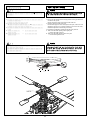
送信機の初期設定とサーボの動作確認
$ )! % % $ * (
* % $
% !% ! + ' ! % (
スワッシュモードでは、スワッシュミキシングのための送信機の初期
設定が必要です。
ここでは各リンケージのプリセットを行なうため、各社送信機のデー
タシートを基に送信機の初期設定を行います。
チェック
ピッチカーブ、スロットルカーブの入力は でおこないます。
先にピッチカーブ、スロットルカーブを入力すると、サーボホーン
取付の際、ニュートラルがずれるおそれがあります。
送信機にデータを入力する際は、まず最初にスワッシュタイプ
を選択して下さい。
機首方向 本機のスワッシュタイプは図のようになっています。
$ ' $ ! (
送信機別データシート
!"## !!$%& ' '
% #
!
'#-.# '/0"'
% " #
!
()
( )
" !
() *+$,
% !
"
*
%
'
() ( ) "
!+
% '()
!
"
! !
!
!
!
!
& °
"
!+
'
'
"
'
入力のしかたは各送信機の説明書をご覧下さい。
また、数値は送信機、受信機、サーボ、ジャイロ等の組合わせや機体
により、値が変わりますので、個々の微調整を行って下さい。
% +
! % $ !(
- ! 1 % - - ' - (- '- % .! % 1 (
サーボの動作確認
% - ( ' % (
プロポの初期設定が済んだら、サーボが正しい方向に動作するかチェ
ックしましょう。仮にサーボホーンを付けると、動く向きがわかりや
すくなります。
モード "# サーボホーンの動き
確認する箇所
エルロン
スワッシュプレートを後ろから見た図
& $ % $ エレベーター
スワッシュプレートを横から見た図
$ % $ ピッチ
ラダー
!
,
図と動きが一致しないときは、サーボの回転方向が逆になっていま
す。その場合、送信機側でリバーススイッチの設定をしましょう。エ
ルロン、エレベーター、ピッチの場合はその他にミキシング量の調整
が必要となります。(各送信機の説明書を参考にセッティングして下
さい。)
$ %! - ( .! $ ( & - .! % * - - ( / % ! % %
$ %
)! % 0(
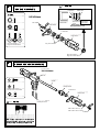
ブレードホルダーの組立
M1.7X5PH........................... 6
C ø8Xø10X1 ....................... 2
注意
内径の大きい方 内径の小さい方
Larger hole
Smaller hole
工場組立済
Pre-assembled
ミゾが内側
Grooves are
inside
ブレードホルダー
Blade holder
M1.7X5PH
ピッチアーム
Blade holder
必ずグリスを塗付
Make sure to
apply grease
Brg. ø5Xø10X4H スラスト
Bearing ø5Xø10X4H thrust
Brg. ø5Xø10X4ZZ .............. 4
C ø8Xø10X1
ブレードホルダー
Blade holder
Brg. ø5Xø10X4ZZ
Brg. ø5Xø10X4Hスラスト .... 2
Brg. ø5Xø10X4H thrust
Brg. ø5Xø10X4Hスラスト
Brg. ø5Xø10X4H thrust
ヨーク/ブレードホルダー部の組立
工場組立済
Pre-assembled
ヨーク
Yoke
スピンドル
Spindle
M3X8CS .............................. 2
ダンパーゴム
Damper rubber
FW ø2.6Xø7.5X0.5Tクロ..... 2
FW ø2.6Xø7.5X0.5T black
C ø5Xø8X3.5
ブレードホルダー
Blade holder
C ø5Xø8X3.5....................... 2
注意
ニードルピン2X15.8
Needle pin 2X15.8
FW ø2.6Xø7.5X0.5Tクロ
FW ø2.6Xø7.5X0.5T black
M3X8CS
ダンパーゴムがヨークから出っ張らないよう
に少量のオイルをつけて、しっかりと押し込
みます。
23
シーソー部の組立
M2ナイロンナット
M2 nylon nut
M2X6CS ........................... 4
ヨーク
Yoke
M2.6X6CS
M2X10CS ........................... 2
EX ø5ボール台付H=6.5
EX ø5 ball with stand H=6.5
M2X12CS D=3.3
M2X12CS D=3.3 ................ 2
ブレードホルダー
Blade holder
M2X12CS D=3.3
M2.6X6CS ........................... 2
Brg. ø2Xø5X2.3 .................. 2
Brg. ø2Xø5X2.3FZZ ........... 4
Brg. ø3Xø6X2.5FZZ
工場取付済
Already attached prior
to shipment.
C ø2.6Xø3X3.4 F5X0.5
EX ø5ボール台付H=6.5
EX ø5 ball with stand H=6.5
C ø2.6Xø3X3.4 F5X0.5 ...... 2
C ø2Xø3.2X1.8 ................... 2
Brg. ø2Xø5X2.3
工場取付済
Already attached prior
to shipment.
EX ø5ボール ...................... 2
EX ø5 ball
シーソー
Seesaw
EX ø5ボール台付 ............... 2
EX ø5 ball with stand
Brg. ø3Xø6X2.5FZZ M2.6X6CS
工場取付済
Already attached prior to shipment.
M2ナイロンナット
M2 nylon nut
C ø2.6Xø3X3.4 F5X0.5
Brg. ø2Xø5X2.3
工場取付済
Already attached prior to shipment.
EX ø5ボール台付H=6.5 ...... 2
EX ø5 ball with stand H=6.5
M2ナイロンナット............ 2
M2 nylon nut
Brg. ø2Xø5X2.3FZZ
工場取付済
Already attached prior to shipment.
M2X10CS
ヨーク
Yoke
ブレードホルダー
Blade holder
M2X6CS
EX ø5ボール
EX ø5 ball
ミキシングアーム
Mixing arm
EX ø5ボール台付
EX ø5 ball with stand
C ø2Xø3.2X1.8
M2X6CS
M2X6CS
EX ø5ボール台付
EX ø5 ball with stand
ミキシングアーム
Mixing arm
C ø2Xø3.2X1.8
Brg. ø2Xø5X2.3FZZ
工場取付済
Already attached prior to shipment.
段のある方が外側
Notch should be facing outside.
24
EX ø5ボール
EX ø5 ball
M2X6CS
M2X10CS
スタビアーム部の組立
M2X12CS D=3.3
仮止め
Temporarily set
M3X3SS
M2X12CS D=3.3................. 4
M3X3SS .............................. 4
スタビコントロールアーム
Stabilizer control arm
クロスメンバーM2X63(ø5ボール付き)
Cross member M2X63 (with ø5 ball)
仮止め
Temporarily set
M3X3SS
スタビコントロールアーム
Stabilizer control arm
クロスメンバーM2X63(ø5ボール付き)
Cross member M2X63 (with ø5 ball)
ロッドエンドM2X12.5
Rod end M2X12.5
16mm
M2X12CS D=3.3
スタビライザーバー
Stabilizer bar
スタビコントロールロッド
Stabilizer control rod
スタビブレード部の組立
スタビコントロールアームとシーソーの間にガタが出ないよう、スタビコントロー
ルアームを矢印の方向に押さえながら仮止めしてあるM3X3SS を締めて下さい。
To ensure that there is no play between the stabilizer control arm and seesaw, tighten the
M3X3SS while pressing the stabilizer control arm in the direction of the arrow.
瞬間接着剤
Instant adhesive
M3X3SS .............................. 4
注意
約1mm
Approx. 1 mm
ロッドエンド
Rod end
M3X3SS
スタビライザーブレードのバラン
スを取り、軽い方にテープなどを
巻いて調整してください。
B
瞬間接着剤
Instant adhesive
スタビライザーバー
Stabilizer bar
A
A=B
M3X3SS
注意
注意
スタビストッパー
Stabilizer stopper
スタビストッパーの方向にご注意ください。
Note the direction of the stabilizer stopper.
奥までネジ込みます。
Screw the bar all the way in.
スタビブレード
スタビライザーバー M3X3SS
Stabilizer blade
Stabilizer bar
スタビライザーブレードとスタビライザー
コントロールアームは平行であること。
25
スタビストッパー
Stabilizer stopper
ネジ切り
Threads
M3X3SS
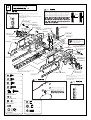
スワッシュプレートの組立
M2X6CS
EX ø5ボール台付
EX ø5 ball with stand
M2X6CS
M2X6CS ........................... 7
M2X12CS D=3.3
EX ø5ボール
EX ø5 ball
M2X12CS D=3.3 ................ 1
EX ø5ボール ...................... 3
EX ø5 ball
EX ø5ボール台付 ............... 4
EX ø5 ball with stand
EX ø5ボール台付
EX ø5 ball with stand
ø3.5ラジアスピン
ø3.5 radius pin
EX ø5ボール
EX ø5 ball
ø3.5ラジアスピン............... 1
ø3.5 radius pin
M2X6CS
スワッシュプレート
Swash plate
EX ø5ボール台付
EX ø5ボール
EX ø5 ball with stand
EX ø5 ball
ウォッシュアウト部の組立
M2X6CS ............................. 2
M2X8CS ............................. 2
スライドブロック
Slide block
工場組立済
Pre-assembled
ø1.5 Eリング
ø1.5 E-ring
溝付き平行ピン2X11.8
Grooved parallel pin 2X11.8
FW ø1.7 ............................... 2
Brg. ø2Xø5X2.3FZZ
EX ø5ボール台付 ............... 2
EX ø5 ball with stand
FW ø1.7
Brg. ø2Xø5X2.3FZZ ........... 4
M2X6CS
ø1.5 Eリング ...................... 4
ø1.5 E-ring
ラジアスアーム
Radius arm
EX ø5ボール台付
EX ø5 ball with stand
Brg. ø2Xø5X2.3FZZ
M2X8CS
ウォッシュアウトコントロールアーム
Wash-out control arm
26
M2X6CS
注意
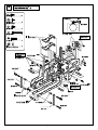
メインギヤの取付
注意
タイミングベルトは、ドライバー等で軽く押し
て、わずかにたわむ程度に張ります。
仮止めしていたM2.6X6CS
を本締めします。
Securely tighten the M2.6 X 6CS
(2 locations) which had previously
been temporarily tightened.
メインマスト
Main mast
メインマスト
Main mast
マストロック
Mast lock
M3X3SS
真ん中の穴を使用
してください。
Use the holes
positioned at center.
M2.6ナイロンナット
M2.6 nylon nut
ベルトの回転方向を確認します。
!
" ! テールプーリー
Tail pulley
メインプーリー
Main pulley
バッテリーホルダー
Battery holder
メインプーリーにベルトを掛けてから
メインマストを通してください。
Place the belt around the main pulley and
then insert the main mast.
ポイント
' メインプーリー56T
Main pulley 56T
M2.6X15CS
メインギヤを取付ける前
にバッテリーホルダーを
取付けてください。
M2.6X8CS
Brg. ø10X12Lワンウェイ(HF)
刻印が下になります。
Brg. ø10X12L one way (HF)
Point the side with the punch mark down wards.
M2.6ナイロンナット
M2.6 nylon nut
工場組立済
Pre-assembled
M2.6X8CS ........................... 2
注意
Brg. ø10Xø15X4ZZ
%&%""
' %&%""
M2.6X15CS ......................... 1
M3X4ボタンボルト........... 6
M3X4 button bolt
M3X3SS .............................. 2
M2.6ナイロンナット ........ 3
M2.6 nylon nut
メインマストをいっぱい引っぱり上げ、マストロッ
クを通し
で締付けます。
工場組立済
Pre-assembled
マストロックを
いっぱい下げる。
Completely lower the
mast lock.
オートロ駆動軸
Auto-rotation drive shaft
メインマストを引っぱり
上げる。
Raise the main mast.
マストロック
Mast lock
ストップリングWR-10
Stop ring WR-10
平らな方が上
Place with the flat
surface facing up.
メインギヤ94T
Main gear 94T
注: マストが上下にあそびがない事。
# $ M3X4ボタンボルト
M3X4 button bolt
27
尾翼の取付
M2X8CS ............................. 2
M2X12CS D=3.3 ................ 2
M2X15CS
M2X15CS ........................... 2
FW ø2Xø6X0.4T ................. 2
FW ø2Xø6X0.4T
M2ナイロンナット ........... 4
M2 nylon nut
EX ø5ボール台付 ............... 2
EX ø5 ball with stand
水平尾翼
Horizontal fin
M2ナイロンナット
M2 nylon nut
尾翼バンド(U)
Horizontal fin band (U)
M2X8CS
尾翼バンド(L)
Horizontal fin band (L)
M2ナイロンナット
M2 nylon nut
EX ø5ボール台付
EX ø5 ball with stand
M2X12CS D=3.3
28
垂直尾翼
Vertical fin
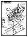
ローターヘッド部ウォッシュアウト部スワッシュプレート部の取付
M2.6X15CS ......................... 1
M2.6ナイロンナット ........ 1
M2.6 nylon nut
ヨークの溝にM2.6
ナイロンナットが
はまり込みます。
The M2.6 nylon nut
fits the groove of the
yoke.
M2.6X15CS
M2.6ナイロンナット
M2.6 nylon nut
ウォッシュアウト
Wash-out
スワッシュプレート
Swash plate
注意
オイル
Oil
ラジアスステーを後ろに少し曲げてø3.5ラジ
アスピンをラジアスステーの溝に入れてく
ださい。
Slightly tilt the radius stay backwards and insert
the ø3.5 radius pin into the slot in the radius stay.
入りにくいときはM3X12TSトラス2を外して
ラジアスステーを後ろに傾けてください。
If it is difficult to do so, remove the M3X12TS
truss-2 and then tilt the radius stay backwards.
スライドブロックの動きが堅い場合は、
メインマストに通して上下に動かし慣ら
してください。
29
ローターヘッド部のリンケージ
ミキシングアームロッド(2セット)
Mixing arm rod (2sets)
35mm
ロッドエンド ................... 10
Rod end
ロッドエンドM2X9 .......... 4
Rod end M2X9
約16mm
Approx. 16 mm
ピッチロッド(2セット)
Pitch rod (2sets)
10mm
ロッドエンドM2X9
Rod end M2X9
約2mm
Approx. 2 mm
SWMフロントレバー/スワッシュロッド
SWM front lever / swash rod
40mm
SWM T型レバー/スワッシュロッド(2セット)
SWM T-type lever / swash rod (2sets)
40mm
約19mm
Approx. 19 mm
注意
約19mm
Approx. 19 mm
メインブレード取付後、実際にピッチを測って再
調整を行います。
ピッチロッド
Pitch rod
ピッチロッド
Pitch rod
ミキシングアームロッド
Mixing arm rod
SWM T型レバー/スワッシュロッド
SWM T-type lever / swash rod
ミキシングアームロッド
Mixing arm rod
SWMフロントレバー/
スワッシュロッド
SWM front lever /
swash rod
SWM T型レバー/
スワッシュロッド
SWM T-type lever /
swash rod
30
26
SWMのリンケージ-1
ポイント
Point
SWM linkage -1
ナット
ボール
ロッドエンド
5 0
サーボホーン
リチウムポリマーバッテリーの過放電を防ぐため、リンケージの設定を行う場合、
受信機用電源は各送信機メーカー付属のバッテリー等を利用するとよいでしょう。
To prevent overdischarge of the lithium polymer battery, use the
manufacturer-supplied battery that comes with the transmitter to
power the receiver when setting the linkage.
注意
%ロッド① 3セット4
% ① 34
/!!
Caution
使用するサーボによって、ロッドの長さは多少変わ
りますので、サーボに合わせて微調整を行ってくだ
さい。
The lengths of the rods vary to some degree
depending on the servos used. Fine-tune them
accordingly.
約0!!
1--2 0 !!
ナット
ボール
%ロッド①
% ①
サーボに付属のネジ
"( " ( ニュートラル
モード モード 送信機のスティックの位置
! "#
・送信機のエルロン、エレベーター、スロットル
の各スティック、およびトリムがニュートラル
の時、右図のように、$型レバーが水平のときに
サーボホーンと$型レバーのボールの位置が平行
になるように、ロッドの調整をしてください。
・% !& ' ' "# ( ! ' )! ) * $+,- - ) - ( $+,- . 6/7
6/7
水平
8. !!
!!
$型レバー
$+,- 平行
27
SWMのリンケージ-2
SWM linkage -2
M2X6CS ............................. 2
注意
SWMロッド③ (2セット)
SWM rod ③ (2sets)
16mm
M2ナット ........................... 2
M2 nut
Caution
使用するサーボによって、ロッドの長さは多少変わりま
すので、サーボに合わせて微調整を行ってください。
The lengths of the rods vary to some degree depending
on the servos used. Fine-tune them accordingly.
約0mm
Approx. 0 mm
EXø5ボール ....................... 2
EX ø5 ball
ロッドエンド ..................... 4
Rod end
M2ナット
M2 nut サーボホーン
Servo horn
EX ø5ボール
EX ø5 ball
M2X6CS
サーボに付属のネジ
Screw included with the servo
ニュートラル
Neutral
モード I
モード II
Mode I
Mode II
送信機のスティックの位置
Position of the transmitter stick.
90°
・SWMロッド③を取付調整後、機体を正面から見て、スワッ
シュプレートがマストに対して直角であることを確認して
ください。
・傾いている場合は 25 で取付けたSWM T型レバー/スワッシ
ュロッドの長さを調節し、直角にしてください。
・After having conducted installation adjustments on the SWM rod
③, looking at the unit from the front, make sure the swash plate
and the mast are perpendicular to each other.
・When inclined, adjust the length of the SWM T-type lever/swash
rod installed in section 25 and set it perpendicular.
スワッシュプレート
が直角になるように
長さを調節する。
Adjust the length so
that the swash plate
is perpendicular.
90°
・送信機のエルロン、エレベーター、ス
ロットルの各スティック、およびトリ
ムがニュートラルの時、右図のように、
T型レバーが水平のときにサーボホーン
とT型レバーのボール位置が平行になる
ように、ロッドの調整をしてください。
・With the transmitter’s aileron, elevator, and
throttle sticks as well as the trim in neutral,
refer to the diagram in the right and adjust
the rod so that the servo horn and T-type
lever ball positions are aligned in parallel
when the T-type lever is horizontal.
SWMロッド③
SWM rod ③
正面から見た図
Front view illustration
水平
Horizontal
12.5 mm
12.5 mm
90°
90°
平行
Parallel
32
T型レバー
T-type lever
28
SWMのリンケージ-3
SWM linkage -3
注意
&3'4 &
ロッド② *&セット+
② *& +
&ナット &
& Caution
使用するサーボによって、ロッドの長さは
多少変わりますので、サーボに合わせて微
調整を行ってください。
$%
The lengths of the rods vary to some
degree depending on the servos used.
Fine-tune them accordingly.
約&'
("" ) &' &7378トラス
&7378 53 6%ボール台付 &
53 6% ! &374
ロッドエンド $
- &ナット
& サーボホーン
&3'4
53 6%ボール台付
53 6% ! &7378トラスと&374が干渉する場合は、
サーボプレートの向きを変えて高さを調整する
か、&374の先端を削ってください。
&7378
&374
!9 " " &374
ニュートラル
サーボに付属のネジ
ロッド② *&セット+
② *& +
・SWMロッド②を取付調整後、機体を横から見て、スワッシュプレートがマスト
に対して直角であることを確認してください。
・傾いている場合は 25 で取付けたSWMフロントレバー/スワッシュロッドの長さ
を調節し、直角にしてください。
・After having conducted installation adjustments on the SWM rod ②, looking at the unit
from the side, make sure the swash plate and the mast are perpendicular to each other.
・When inclined, adjust the length of the SWM front lever/swash rod installed in section
25 and set it perpendicular.
./0
モード モード 送信機のスティックの位置
・送信機のエルロン、エレベーター、スロットルの各ス
ティック、およびトリムがニュートラルの時、右図の
ように、 フロントレバーが水平のときにサーボ
ホーンと トルクレバーのボール位置が平行にな
るように、ロッドの調整をしてください。
・ ! " "
# スワッシュプレート
が直角になるように
長さを調節する。
Adjust the length so
that the swash plate
is perpendicular.
フロントレバー
水平
1 #
2&% 2&% ./0
./0
平行
トルクレバー
ラダーのリンケージ
M2X6CS ............................. 1
サーボホーン
Servo horn
M2ナット ........................... 1
M2 nut
M2ナット
M2 nut
M2X6CS
EXø5ボール ....................... 1
EX ø5 ball
EX ø5ボール
EX ø5 ball
ロッドエンド ..................... 1
Rod end
ロッドアジャスター
Rod adjuster
はめ込みます。
Fit in.
ラダーコントロールロッドL=415
Rudder control rod L=415
ロッドエンド
Rod end
サーボに付属のネジ
Screw included with the servo
右
Right
中立
Neutral
中立
Neutral
左
Left
90゜
10mm
左
Left
中立
Neutral
右
Right
モード I
Mode I
カット
Cut
サーボホーン:ニュートラル
Servo horn: neutral
テールピッチプレート
Tail pitch plate
平行
Parallel
左
Left
右
Right
モード II
Mode II
プロポ
スティック、トリム:ニュートラル
Transmitter
stick / trim: neutral
34
機首方向
Direction of the
nose of the unit
テールピッチレバー
Tail pitch lever
左
Left
中立
Neutral
右
Right
上から見た図
Top view illustration
テールブームパイプに対して平行の位置(初期設定)
Positioned at parallel to the tail boom pipe (initial setting)
ホバリングの回転数によって変化しますので、フライ
トをして調整します。
Because it changes depending on the number of rotations when
hovering, first fly the unit and then make adjustments.
メインブレードの組立
M3X20CS
M3X20CS ........................... 2
M3ナイロンナット ........... 2
M3 nylon nut
ブレードスペーサーø3Xø20X1T
Blade spacer ø3Xø20X1T
C ø3Xø5X9
(圧入済)
(Already press-fitted in)
メインブレード
Main blade
M3ナイロンナット
M3 nylon nut
メインブレードのバランスをとります。
Balancing main rotor blades
注意
メインブレードは軽く動くようにネジを締め付けます。
軽い方にテープ、デカールなどを巻きます。
Apply tape or decals to the lighter end.
35
ピッチの測り方
注意
メインブレード
Main blade
必ずヒロボー製ピッチゲージ
を使用してください。
前
Front
1. メインブレードの先端から約80mmのと
ころにピッチゲージを取付け、メインブ
レードを機体の前方に向けてください。
Install the pitch gage at about 80mm from the
tip of the main blade and point it towards the
front of the unit.
スタビライザーバー
Stabilizer bar
!
約80mm
2. 送信機のスロットルスティックを動かし、スタビラ
イザーバーとピッチゲージを平行にし、指された目盛
りを読んでください。測定するときは実際に飛行して
いるときのようにメインブレードの先端を軽く持ち上
げて測るとより正確に測れます。
Move the transmitter’s throttle stick, make the stabilizer
bar and pitch gage horizontal, and read the indicated
graduations. When measuring, hold the tip of the main
blade up slightly to simulate its position during flight for a
more accurate measurement.
注意
ピッチゲージ
Pitch gauge
スタビライザーバー
Stabilizer bar
ピッチを測るとき、スライドブロックとヨークが干渉したり、ピンから抜けないよう調整してください。
While measuring the pitch, adjust the length of the rods so that the slide block will not touch the yoke and it will not come off the pin.
ヨーク
Yoke
ぶつかる
Touches.
スライドブロック
Slide block
チェック
ヨーク
Yoke
ぬける
Comes off.
⇨
"
チェック
ハイピッチのとき、スライドブロッ
クとヨークが干渉しませんか?
スライドブロック
Slide block
"
ローピッチのとき、ピンからスライ
ドブロックが抜けることはありませ
んか?
" # " #
$" % " & !
" # " #
&& % " & %!
36
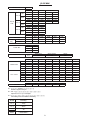
ピッチ/スロットルの設定
■ピッチの設定
① 送信機のピッチカーブ機能にデータが入力されていないことを確認して下さい。
もし入力されている場合はデータを消去して下さい。(詳しくは送信機の説明書
をご覧下さい。)
② 送信機のスロットルスティック中立のとき、メインブレードのピッチが0°になる
ように、ピッチロッドの長さを調整します。※必ず両方のメインブレードを調整
してください。
③ ピッチの全ストローク(ローピッチとハイピッチの差)が約22°〜24°になってい
るか確認して下さい。例えばローピッチが–11°の場合、ハイピッチが11°ならば
11°– (–11°) =22°になります。もし全ストロークが22°〜24°にならないときは送
信機のスワッシュモード用舵角調整機能(スワッシュAFR、スワッシュミキシング、
CP-EPA等)を使用して、22°〜24°になるようデータを入力して下さい。
ハイピッチ
High pitch
中立
Neutral
ローピッチ
Low pitch
■Pitch setting
① Check that no data has been input into the pitch curve function of the transmitter. If any
data has been input, delete it. (Refer to the transmitter instruction manual for the details.)
② Adjust the length of the pitch rods so that the main blade pitch is 0° when the transmitter
throttle stick is at neutral.
* Adjust for both main blades.
③ Check that the full stroke (the difference between the low pitch and high pitch) is set to
approximately 22° to 24°. For example, if the low pitch is set to –11° and the high pitch is
set to 11°, then it is 11° – (–11°) = 22°. If the full stroke does not become 22° to 24°, use
the transmitter’s rudder angle adjustment functions for swash mode (swash AFR, swash
mixing, CP-EPA, etc), and input data so that it becomes 22° to 24°.
■ピッチカーブの設定
Hovering
3D
1800rpm〜1900rpm
2500rpm〜2600rpm
■Pitch curve setting
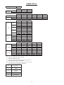
(設定の行い方は、ご使用の送信機の説明書をご覧ください。)
各コンディションごとのピッチ角が下の表のようになるよう送信機のピ
ッチカーブ機能にデータを入力して下さい。
※このデータはコンピュータプロポを使用のものです。
使用するモーター、スピードコントローラー、サーボ等により変化し
ます。一般的な目安です。
コンディション
Condition
ピッチカーブ(参考)
Pitch curve (reference)
ホバリング
Hovering
メインローターの回転数の目安
ホバリング 1800rpm〜1900rpm
3D
2500rpm〜2600rpm
(Refer to your transmitter’s instruction manual for radio specific pitch curve
setting descriptions).
Adjust your radio’s pitch curve percentages so the following suggested pitch
curve degrees are measured on your helicopter at the low, mid and high points.
* Computer Propo is used for the data.
Note: Actual values can vary depending on your selection of motor, speed
controller, or servos, etc., and this data is thereby a general guideline only.
N
ID1
(ホバリング) (ループ系)
Hovering
Loop
ID2
(ロール系)
Roll
3D
オートローテーション
Auto-rotation
11˚ 〜12˚
ハイピッチ
High pitch
7˚
7˚ 〜 7.5˚
7˚ 〜 7.5˚
7.5˚ 〜 8˚
ニュートラル
Neutral
5˚
2˚
0˚〜1˚
0˚
ローピッチ
Low pitch
-2.5˚ 〜 -3˚
-4˚
-5˚
-7.5˚ 〜 -8˚
100%
ループ系
Loop
100%
ロール系
Roll
3D
100%
100%
-6˚ 〜 -7˚
オートローテーション
Auto-rotation
100%
50%
50%
50%
50%
50%
0%
0%
0%
0%
0%
スティック:ロー スティック:中立 スティック:ハイ スティック:ロー スティック:中立 スティック:ハイ スティック:ロー スティック:中立 スティック:ハイ スティック:ロー スティック:中立 スティック:ハイ スティック:ロー スティック:中立 スティック:ハイ
Stick: Low Stick: Center Stick: High Stick: Low Stick: Center Stick: High Stick: Low Stick: Center Stick: High Stick: Low Stick: Center Stick: High Stick: Low Stick: Center Stick: High
■スロットルカーブの設定
■Throttle curve adjustment
スロットルカーブは、バッテリー、モーター、スピードコントローラー、
および気候等により変化します。下のグラフや巻末のデータシートを参
考にデータを入力した後、実際にフライトをして微調整をして下さい。
スロットルカーブ(参考)
Throttle curve (reference)
ホバリング
Hovering
100%
ループ系
Loop
A throttle curve can vary due to battery, motor, speed controller, weather, etc.
The below graphs and data at the end of this manual are starting points only and
will require finer tuning after first flights have been made.
ロール系
Roll
3D
オートローテーション
Auto-rotation
100%
100%
100%
100%
50%
50%
50%
50%
50%
0%
0%
0%
0%
0%
スティック:ロー スティック:中立 スティック:ハイ スティック:ロー スティック:中立 スティック:ハイ スティック:ロー スティック:中立 スティック:ハイ スティック:ロー スティック:中立 スティック:ハイ スティック:ロー スティック:中立 スティック:ハイ
Stick: Low Stick: Center Stick: High Stick: Low Stick: Center Stick: High Stick: Low Stick: Center Stick: High Stick: Low Stick: Center Stick: High Stick: Low Stick: Center Stick: High
37
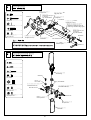
モーターの取付
M3X5CS ............................. 4
ピニオンギヤ24T
Pinion gear 24T
M3X5SS .............................. 2
ピニオンギヤ
Pinion gear
24T ―― 4セル用
For 4 cells
26T ―― 3セル用
For 3 cells
ピニオンギヤ26T
Pinion gear 26T
M3X5SS
モーターのDカット部分に
M3X5SSがくるように
取付けてください。
Position the pinion gear so that
the M3X5SS (2 pcs) fit in the
D-shaped cut holes of the motor.
M3X5CS
注意
飛行後のモーターは高温になっております。
火傷防止のためモーターに触れないようにして
ください。
The motor becomes extremely hot after flight.
To avoid burns, do not touch the motor.
後
Rear
前
Front
ヒロボー純正モーターを使用するときは
上図の3箇所でネジ止めしてください。
When using a genuine Hirobo motor, fix it by
tightening the three screws as shown in the
figure above.
他社製モーターを使用するときは各モーターに合う穴を選んでネジ止めし
てください。
M3X5CSが締めにくい場合は、ボールポイントレンチを使用してください。
When using a motor other than Hirobo’s, use screw holes that match the motor.
If it is hard to tighten the M3X5CS, use a ballpoint wrench.
バックラッシュの調整
Backlash adjustment
メインギヤとピニオンギヤの間にはわずかな隙間が必要です。
メインギヤとピニオンギヤの間にビニール袋の切れ端を噛み合
わせた状態でモーターを固定してください。
A small gap is necessary between the main gear and pinion gear.
Fix the motor with a piece of plastic bag sandwiched between the
main gear and pinion gear.
38
スピードコントローラーの取付
注意
飛行後のスピードコントローラーは高温になっております。
火傷防止のためスピードコントローラーに触れないようにし
てください。
The speed controller becomes extremely hot after flight.
To avoid burns, do not touch the speed controller.
M3X12CS ........................... 2
スピードコントローラーの使用方法や設定の方法については、各スピ
ードコントローラー付属の説明書をご覧ください。
For operation and setting of the speed controller, please refer to the operation
manual supplied with the speed controller.
C ø3Xø5.2X2 ...................... 2
M3X5CS .............................. 4
M3X5CS
M3X5CS
C ø3Xø5.2X2
M3X5CS
M3X12CS
クロスメンバーM3X26
Cross member M3X26
注意
ヒロボー純正スピードコントローラーを使用するときはフレーム側面
にネジ止めしてください。その他のスピードコントローラーを使用す
るときはメインフレームやマグネシウムセンターフレームに両面テー
プなどで固定してください。
スピードコントローラーは最大電流60A以上
のものを使用してください。
Use a speed controller with a maximum
current of 60 A or higher.
When using a genuine Hirobo speed controller, fix it to the frame side face
with screws.
When using a speed controller other than HiroboÕs, fix it to the mainframe or
magnesium center frame with double-sided tape.
39
配線とバッテリーの搭載
Wiring and battery mounting
HIROBO純正モーターおよび純正スピー
ドコントローラーを使用する場合、同じ
色のコネクターを接続します。
If using a Hirobo motor and a Hirobo speed
controller, connect the same color connectors.
受信機のスロットル
チャンネルへ
To the receiver throttle
channel
スイッチ
$#
%&'(!$
モーターとスピードコントローラーのコ
ネクターを接続します。
モーターが逆回転するときは3本の内2本
を入れ替えると回転方向が変わります。
! " # #
# # フライトなどの激しいフライトをするとき
は、バッテリーを両面テープやマジックテープ
(別売)で貼付けてください。
キャビンを取付けた状態で重心位置がメ
インマストの軸線上にくるようにバッテ
リーの前後位置を調整します。
Adjust the battery position by moving it
back and forth so that the gravity center of
the helicopter with the cabin installed will be
aligned with the axis line of the main mast.
付属のマジックテープで
しっかりしばってください。
$ #
# 注意 レプトン用純正バッテリー(LEXリポバッテリー14.8V 3200mAh)は
1セルあたりの電圧が2.7V以下になると再使用(充電)できません。
使用後は必ずバッテリーとスピードコントローラーのコネクターを外
してください。接続した状態での保管は、バッテリーが過放電し使
用不能となります。
フライト中パワーダウンを感じたらすぐに使用を中止し充電をおこ
なってください。
! " # ! # $ %&
! && ! " ' & ""
( " #"!
! # " #
! && " ) " " # $
#"!
!
* % +
#"! # # ! "& , "
! # !
" " $ " &$ # & バッテリーホルダー
Battery holder
バッテリーホルダーの取付位置を前後に移動させ、
バッテリーの搭載位置を調整することができます。
Adjust the battery mounting position by moving the
battery holder position back and forth.
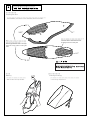
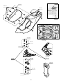
キャビン/キャノピーの加工
キャビンの加工
Preparing the cabin
組立前に、キャビンの不要部分をカッターなどで切り取ってください。
Before assembly, use a cutter to cut off unnecessary sections of the cabin.
カット
Cut
カット
Cut
キャビン
Cabin
リンケージロッドやスワッシュプレートが
干渉しないようカットしてください。
Cut off the cabin so that it does not touch
the linkage rods or the swash plate.
3Dフライトなど、バック飛行をする
場合はカットせずにキャノピーをそ
のまま取付けてください。
When flying backwards such as 3D flight,
attach the canopy without cutting the
cabin.
カット
Cut
カット
Cut
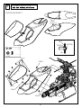
注意
カッター等の刃物を使用する際は、ケガをしない
よう十分に注意してください。
水洗い
Washing
キャノピーの加工
Trimming the canopy
キャビンをセッケン水で洗います。
Wash the cabin with soap and water.
キャノピーをカットラインに合わせてカットします。
Cut the canopy along the lines.
41
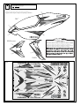
キャビンキャノピーの取付
キャビン・キャノピーの組立
Cabin and canopy assembly
ø1.5 穴開け
Make ø1.5 holes
キャビン
Cabin
グロメット
Grommet
M2X5TS ............................ 10
内側
Inside
グロメット ......................... 4
Grommet
M2X5TS
グロメット
Grommet
M2X5TS
グロメット
Grommet
グロメット
Grommet
42
ボディマウント
Body mount
デカールの貼付け
パッケージを参考に、デカールを貼ってください。
Apply the decals using the images on the package as reference.
②
キャビン
Cabin
①
④
③
水平尾翼
Horizontal stabilizer
アドバイス
⑥
大型のデカールを貼る際には、デカールの粘面とキャビ
ンの両方に薄いセッケン水や、市販の自動車用品ウィン
ドフィルム貼りスプレー等を吹きかけてください。
デカールの位置決めが容易になり、また気泡ができにく
なるので、きれいに美しく貼ることができます。
⑤’
⑤
⑦
垂直尾翼
Vertical fin
デカール
Decal
43
3. フライト編 Flight
ヘリコプターは、メインローター、テールローターが高速で回転します。
飛行には次の事に十分注意し、安全なフライトをお楽しみ下さい。
The helicopter’s main and tail rotors spin at very high speeds. Make sure to
follow these instructions for a safe and enjoyable flight.
Transporting the unit
機体の運搬
飛行場までの機体の運搬で、車内で機体が倒れたりすることのない
よう、きちんと固定して下さい。きちんと固定していないと、部品
の破損につながり、安全なフライト性能が得られなくなる可能性が
あります。
When transporting the unit to an airfield, secure it in a way so as to prevent
it from falling over to reduce the risk of breakage of the components which
would compromise flight performance and safety.
警告
飛行の場所
飛行させてはいけない所
○ 近くに人がいる
○ 近くに建物がある
○ 線路、幹線道路、電線などに近い所
Warning
The airfield
○ Near people
○ Near buildings
○ Near roads, railway tracks, or power lines
Caution
注意
Checking the unit before flight
飛行前の機体の点検
○ ネジが確実に締まっているか、もう一度確認して下さい。
新しいうちは、ビス類もゆるみがちです。フライトごとに必ずチ
ェックして下さい。
○ 送信機の電池及びバッテリーの充電、電圧は十分か確認して下さ
い。
○ Check that all of the screws are well fastened. New units tend to have
many loose screws. Make sure to check them before every flight.
○ Check that the transmitter batteries and battery are fully charged.
Safety measures
安全対策
万が一に備えて、「ラジコン保険」の加入をおすすめします。
詳しくは本製品をお買い求めになった販売店へお問い合わせ下さい。
また、安全に使用するために、本取扱説明書の「1.組立を始める前に
必ずお読みください」のページをもう一度よくお読みください。
To be prepared in the event of an accident, we recommend that you take out
an insurance policy for radio controlled model aircraft. For more details,
contact your dealer.
Furthermore, in order to ensure safe use of this product, please reread the
“Read before assembly” contained in this instruction manual one more time.
44
イメージフライト
● 操縦の基本となる各舵の動きを指先に覚え込ませます。自然に指
が動くようになるまで反復練習しましょう!!
● Familiarize your fingers with the basic steering controls used to operate
this unit. Practice repeatedly until your fingers move naturally.
1. 機体を置き、送信機を持って機体の後ろに立ちます。
(送受信機の電源は OFF の状態)
2.「エルロン右・左、ラダー右・ 左 、エレベーターアップ・ ダ ウ
ン、スロットルハイ・ ス ロー・・・」と声を出しながらスティッ
ク操作を練習します。
このとき、スティック操作とともに、機体の動く方向をイメージ
しながら行なうとよいでしょう。
※このイメージ練習は後のフライトで必ず目に見えない効果を発揮
します。十分に反復練習を行ないましょう。
1. Place the unit on the ground and stand behind it, holding the transmitter.
(Make sure the transmitter power is turned off.)
2. Practice operating the stick while saying out loud, “aileron left/right”,
“rudder left/right”, “elevator up/down”, “throttle up/down” and so on. As
you move the control sticks, try to visualize how the unit will move in
response.
Note: This visualization training is very effective and should be practiced
repeatedly.
● RC flight simulator for PCs is a good practice tool to learn each rudder
movement.
● パソコンのRCフライトシミュレーターも各舵の動きを覚えるのに
有効な練習方法です。
送信機のスティックと機体の動き
モード I
エ
レ
ベ
ー
タ
ー
Mode II
Aileron
左
Left
左
右
Left
右
Right
Right
ダウン
Down
アップ
Up
ダウン
Down
アップ
Up
Elevator
エ
ル
ロ
ン
ラ
ダ
ー
Rudder
右
Right
左
Left
右
Right
左
Left
Up
下降
Down
上昇
Up
Throttle
ス
ロ
ッ
ト
ル
上昇
下降
Down
45
フライトに出かけよう
再確認をしましょう
"
忘れずに持っていくもの
☆ → % & '
☆ % ' ( '
☆もう一度チェック → ネジは確実に締まっていますか
☆送信機用のバッテリーはそれぞれ充分に充電されていますか
① 送信機:バッテリーは充分に充電されていますか
② バッテリー
③ 充電器
④ 充電用バッテリー
⑤ 工具 ※ フライトするために必要なものを見て確認しましょう。
①
② ③ ④ ⑤ ! " #
飛行場に着いたら
周波数の確認をしてください。
% " # 警告
近くにラジコン模型で遊んでいる人がいたら、必ず使っている周
波数を確認します。また、自分の使う周波数を相手に伝えます。
同じ周波数を同時に使用した場合、誤作動・操縦不能などの事態
が発生し大変危険です。墜落による機体の破損から、重大な事故
を引き起こす恐れがあります。
!
" " # ! # ! " $ ! ! !
警告
初心者の練習の場合、風が強い日は避けてください。無風〜微風
のときに行いましょう。
バッテリーの搭載
,- フライトなどの激しいフライトをするとき
は、バッテリーを両面テープやマジックテープ
(別売)で貼付けてください。
. " ' ,- /
'0'' '( " ' " !' " #
重心位置がメインマストの軸線上にくるよう
にバッテリーの前後位置を調整します。
%') " ( '
( "
& ' & ' & * 付属のマジックテープで
しっかりしばってください。
+ &
' " 電源を入れる順番
②受信機の電源スイッチがOFFになっていることを確認し、スピード
コントローラーにバッテリーを接続します。
Check that the power switch is turned off, and then connect the battery to
the speed controller.
①スロットルスティックを最スローの位置にします。
Place the throttle stick in the lowest position.
モード
トリム: 中立
Trim: neutral
注意
スロットルスティックは
最スローの位置
注意
③
レプトン用純正バッテリー(LEXリポバッテリー14.8V 3200mAh)は1セルあ
たりの電圧が2.7V以下になると再使用(充電)できません。
使用後は必ずバッテリーとスピードコントローラーのコネクターを外してくださ
い。接続した状態での保管は、バッテリーが過放電し使用不能となります。
フライト中パワーダウンを感じたらすぐに使用を中止し充電をおこなって
ください。
④
送信機の電源スイッチをON!
Turn on the transmitter
! "!#$ ! %&'( )*++,
", *- ( . / 0 1 受信機 の電源スイッチをON
Turn on the receiver
OFFは、逆の順序
Reverse the above order to turn off
動作確認を行います。
メインローターが回転しないよう、モーターの
コネクターを2本以上抜いてください。
To prevent the main rotor from rotating, remove two
or more motor connectors.
各舵は、スティック通りに動いていますか。
プロポの説明書に従って距離テストを行ないます。
Are the rudders moving in accordance with the controls?
Perform a range test following the transmitterÕs instruction manual.
送信機の電源スイッチをON!
Turn on the transmitter
受信機 の電源スイッチをON
Turn on the receiver
OFFは、逆の順序
Reverse the above order to turn off
47
Adjusting the tracking
トラッキング調整
Caution
注意
トラッキングの調整は危険ですので、機体から10m程離れて行
ないます。
Make sure to adjust the tracking at a distance of at least
10m away from the unit to reduce the risk of danger.
1. スロットルスティックをゆっくりとハイ側に動かし機体が浮かび
上がる直前に止めます。
ローターの回転面を真横から見ます。
2. ローターの軌跡をよく見て下さい。
2枚のローターが同じ所を通っていればOKですが、上下にずれ
ている場合、トラッキング調整が必要です。
3. トラッキング調整はピッチロッドのロッドエンドを回して調整し
ます。
A: 軌跡の高いブレード側
→
ロッドの長さを縮める
のピッチロッド
B: 軌跡の低いブレード側
→
ロッドの長さを伸ばす
のピッチロッド
1. Slowly raise the throttle stick to its high position and stop just before the
unit lifts-off the ground.
Observe the rotation of the rotor from the side of the unit.
2. Carefully observe the path of the rotor.
If both blades appear to move through the same path, it does not need
adjustment. However, if one blade is higher or lower than the other,
immediate adjustment of the tracking is necessary.
3. The tracking is adjusted by turning the rod end of the pitch rod.
A: Pitch rod of the blade spinning with a higher path
→ Reduce the length of the rod.
B: Pitch rod of the blade spinning with a lower path
→ Increase the length of the rod.
Caution
注意
Incorrect tracking causes vibrations. Repeat tracking
adjustments over and over until the rotor is correctly
aligned. After having adjusted the tracking, check once
more that the pitch angle when the unit is hovering.
トラッキングがずれていると振動の原因になります。確実に合
うまで何度も繰り返します。
トラッキング調整を行ったあとでもう一度、ホバリングでのピ
ッチ角を確認して下さい。
A
B
ピッチロッド
Pitch rod
48
Speeding up the Motor
モーターの回転をあげてみましょう
Caution
注意
Make sure that there are no people or obstructions in the
vicinity.
周囲に人のいないことを確認して下さい。
周囲に障害物がないことを確認して下さい。
Warning
警告
Beginners should not attempt to take off suddenly. Move
the throttle stick slowly and under no circumstances
should you move it suddenly.
初めての方はいきなり地面から離れないようにしてください。
また、スロットルスティックは少しずつ操作するようにし、急
激な操作は絶対にしてはいけません。
1. 機体は機首を風上に向けて置きます。
2. 機体のななめ後方10mほどのところに立ちます。
3. スロットルスティックをゆっくり上げていきます。
4. 機体が浮き上がりそうになったらスロットルスティックを最スロ
ーに戻します。
1. Point the nose of the unit directly into the wind.
2. Stand about 10m diagonally behind the unit.
3. Slowly push the throttle stick.
4. When it looks as though the unit is about to take off, return the throttle
stick to the lowest position.
風上
Wind Direction
モードI
アンテナは完全に伸ばして下さい。
Extend the antenna completely.
Mode II
10m
ゆっくりとスロットルスティッ Slowly raise the throttle stick
クをハイ側に上げて下さい。
towards its high position.
49
Adjustment of trim
トリムの調整
機体が浮き上がろうとするとき、機体はいろんな方向へ傾くはずで
す。この傾きを修正することをトリム調整といいます。
When the unit is taking off, there may be a tendency for it to drift in one
direction or another. Correcting this drift is called trim adjustment.
エルロン・エレベーターのトリム調整
Aileron / elevator trim adjustment
1. モーターを停止させ、送信機のスティック、トリムを中立にして
スワッシュプレートを真横・真正面から見て、傾いていないか確
認してください。
傾いている場合はリンケージロッドの長さ調整をして水平にします。
2. 再びモーターを回してみて、まだ機体が傾くようであれば送信機
のトリムレバーを使って調整します。
1. Stop the motor, put the transmitter sticks and trims to the central
positions, and look at the swash plate edge-on and head-on to check if
there is any drift.
If there is any drift, adjust the length of the linkage rods to make them
even.
2. Restart the motor, and if the unit still drifts, use the transmitter’s trim
levers to correct.
左へ傾く
Drifts left
トリムを右に動かす
Move the trim towards right
右へ傾く
Drifts right
トリムを左に動かす
Move the trim towards left
前進する
Drifts forward
トリムをアップに動かす
Move the trim towards up
後退する
Drifts back
トリムをダウンに動かす
Move the trim towards down
モードI
右
Right
前進
Forward
Mode II
エレベーター
ダウン
Elevator
Down
エレベーター
アップ 左 右
左
Left
Elevator
Up Left Right
後退
Back
Rudder trim adjustment
ラダーのトリム調整
ジャイロのテールロック機能をOFFにして行います。
Perform this operation with the gyro tail lock function
turned off.
1.ラダーコントロールロッドのロッドアジャスターを回して調整し
ます。
左の方向へ向く
Turns towards left
ロッドアジャスターを縮める
Shorten the rod adjuster
右の方向へ向く
Turns towards right
ロッドアジャスターを伸ばす
Extent the rod adjuster
1. Adjust the trim by rotating the rod adjuster of rudder control rod.
右
Right
左
Left
モードI
Mode II
テールユニットケース
Tail unit case
左 右
Left Right
縮める
Shorten
伸ばす
Extend
ロッドアジャスター
Rod adjuster
Caution
注意
You cannot perform trim adjustment with the transmitter
with a tail locked gyro. Also turn off the transmitterÕs
revolution mixing function.
テールロック式ジャイロを使用している場合は、送信機でのト
リム調整を行いません。また、送信機のレボリューションミキ
シング機能をOFFにします。
Caution
注意
If the rudder gets misaligned or rotates, it is possible the
rudder servo direction or gyro detection has been reversed.
Please double-check.
ラダーが大きくずれたり、回転してしまう場合は、ラダーサー
ボの動作方向もしくはジャイロの感度方向が逆方向になってい
る可能性があります。再確認してください。
50
Corrective steering and hovering practice
あて舵とホバリングの練習
重要
Important Corrective steering and hovering
あて舵とホバリングについて
Due to the design of the helicopter, even after adjusting the
trim settings, the unit will not rise straight up into the air
simply by pushing the throttle stick. However, by steering in
the opposite direction of the drift, you can keep the unit
balanced, make it go straight up, or keep it stationary. This
kind of steering is called corrective steering, and keeping the
unit stationary is called hovering. Before attempting to fly the
unit, practice corrective steering repeatedly. If you have not
mastered this skill, you will not be able to keep the unit in the
desired space in the air.
ヘリコプターの構造上、トリム調整をしても、スロットルスティ
ックを上げただけで機体がまっすぐに上昇することはありませ
ん。しかし、機体が傾く方向と反対の舵を打ち、バランスを保つ
ことで、機体をまっすぐに上昇させたり、同じ位置に静止させる
ことができます。この舵のことをあて舵といい、機体を同じ位置
に静止させることをホバリングといいます。機体を地面から離す
前に、十分にあて舵の練習を行いましょう。このあて舵が打てる
ようにならないと、空中で姿勢を保つことはできません。
Caution
注意
Make sure that there are no people or obstructions in the
vicinity.
周囲に人のいないことを確認して下さい。
周囲に障害物がないことを確認して下さい。
練習するときは機体の斜め後方10mぐらい離れたところに立ちます。
When practicing, stand approx. 10m diagonally behind the unit.
メインブレードの吹き降ろし風
Main Blade down draft
メインブレードの吹き降ろし風(地面効果)について
地面から1m程度までの高さでホバリングする場合、機体はメイン
ブレードが吹き降ろした風の影響を受けてフラフラします。思い
切って自分の目線の高さほどに上げてみてください。吹き降ろし
風の影響を受けにくくなるため、姿勢が安定してとばしやすくな
ります。
アンテナは完全に伸ばして下さい。
Extend the antenna completely.
Main Blade down draft (Ground effect)
When hovering within 1m off the ground, the unitÕs main blade
creates a down draft which can destabilize the unit. Firmly
raise the unit until it is roughly at eye level. This will lessen the
effect of the down draft and make the unitÕs position easier to
maintain.
Step. 1
スロットル操作の練習
機体が少し上昇したら、スロットルスティックをゆっくりと下げ、
機体を着陸させて下さい。
When the unit begins to lift-off the ground, slowly lower the throttle stick
and bring the unit back down.
機体を上下させ、スロットル操作の感覚を身につけましょう。
Continue to practice raising and lowering the unit from the ground until
you feel comfortable with the operation of the throttle.
モードI
Mode II
ゆっくりとスロットルスティッ Slowly raise the throttle stick
クをハイ側に上げて下さい。
towards its high position.
51
#
エルロン・エレベーター操作の練習
注意
1. スロットルスティックをゆっくりと上げます。
2. 機体が前後左右に動いたら、動いた方向と逆に
エルロン、エレベータースティックを少しずつ
動かし、元の位置にもどるようにしましょう。
1. Slowly raise the throttle stick.
2. When the unit moves in any direction back, forth,
left, or right, gently move the aileron and elevator
sticks in the opposite direction to return the unit to
its original position.
"
機首が動いてしまったときは、必ずスロットルスティッ
クを下げ、着地させ、立ち位置を機体の斜め後方に移動
して練習を再開しましょう。また、機体が遠くに離れて
しまった時も一旦、機体を着地させ、機体からぐら
いのところに近づき、練習を再開しましょう。
ラダー操作の練習
1. スロットルスティックをゆっくりと上げます。
2. 機首が左右に動いたら、動いた方向と逆にラダ
ースティックを少しずつ動かし、元の位置に
もどるようにしましょう。
1. Slowly raise the throttle stick.
2. If the nose of the unit moves left or right, gently
move the rudder stick in the opposite direction to
get the unit back in its original position.
!
円の中で練習をする
STEP. 1〜3 の操作に十分慣れたら更に操作の精度を上げる為、地面に円
などを描き、その円中で移動したりとどまる練習をしましょう。
After you feel comfortable with the maneuvers in steps 1 to 3, increase your
accuracy by drawing a circle on the ground and practice flying the unit within
the range of that circle.
慣れたらだんだん円を小さくする
The more you feel accustomed to the maneuvers,
the smaller you can make the circle.
ヘリの方向を変えて、ホバリングの練習をする
STEP. 1〜4 を十分に練習したら、機体側面に立ち、 STEP. 1〜4 と
同じ練習をします。その後、機体の正面に立ち、同じように
STEP.1〜4 を繰り返し練習しましょう。
After you feel comfortable with the maneuvers in steps 1 to 4, stand
facing the side of the unit and continue practicing steps 1 to 4. Afterwards,
repeat the same steps standing right in front of the unit’s nose.
側面ホバリング
対面ホバリング
※左側、右側両方行いましょう。
Practice standing on both the left and right –hand sides.
52
How to eliminate troubles during flight
フライト時のトラブル脱出法
症状
原因
トラッキング
Tracking
ホバリング時の
ローター回転数
Rotation of the
rotor during
hovering
ジャイロ感度
Sensitivity of the
gyro
対策
合わない
Out of alignment
ピッチロッドによる調整ができて
いない。
Adjustment using the pitch rods has
not been done.
ピッチロッドの長さを調整してトラッキング調整を行
ないます。
Adjust the length of the pitch rods.
回転が低い
Low rotation
メインブレードのピッチ角が高い。
Pitch of the main blade is high.
ピッチロッドを伸ばして調整します。
(ホバリングでローター回転 1,800〜1,900rpmくらい)
Adjust by extending the pitch rod.
(The rotor should rotate at about 1,800 to 1,900rpm during
hovering.)
回転が高い
High rotation
メインブレードのピッチ角が低い。
Pitch of the main blade is low.
ピッチロッドを縮めて調整します。
(ホバリングでローター回転 1,800〜1,900くらい)
Adjust by retracting the pitch rod.
(The rotor should rotate at about 1,800 to 1,900rpm during
hovering.)
ホバリング時にテールが
左右にふらつく
The tail sways left and right
during hovering.
ジャイロ感度が低い
The sensitivity of the gyro is low.
感度を上げます
Increase the sensitivity
全速飛行中にテールが左
右にふれる
The tail sways left and right
during flight at full speed.
ジャイロ感度が高い
The sensitivity of the gyro is high.
感度を下げます
Decrease the sensitivity
以上のことをお調べになって、それでも不具合があるときは使用
を中止し、お買上げの販売店または、当社エンジニアリングサー
ビスにご相談下さい。
Should you still have some doubts even after having tried the above, stop
using the unit and consult your dealer or Hirobo’s Engineering Service
Section.
清掃・保管方法
Cleaning and storage
① 1日のフライトが終了し、清掃をする際は次の点に注意して行って
下さい。
② 機体の油汚れ等は、決して水洗いはしないで下さい。無線機器の
故障や金属部品のサビの原因となります。ウエスで拭き取るか、
アルコールを霧状に散布して、かるくウエスで拭き取るようにし
て下さい。
③ バッテリーのコネクターを外し、機体から取外して保管してくだ
さい。
④ 保管の際、メインブレードは取外し、またスイッチが、OFFの状
態である事を確認して下さい。
⑤ 日の当たる場所、また車内の長時間の放置は変色、変形の原因に
なりますので、注意して下さい。
⑥ 長期保管をする場合は、上記の状態で、風通しのよい場所で保管
して下さい。
① After finishing your flight for the day, follow these steps when cleaning
your model.
② To reduce the risk of damage to the radio controls or of the occurrence of
rust on metal components, never wash oil or other stains with water.
Wipe with a soft cloth or spray the surface with alcohol and wipe the
stains off lightly with a soft cloth.
③ Remove the battery connector and then remove the battery from the
body. Keep the battery in a safe place.
④ Make sure to remove the main blade and turn the switch to the OFF
position when storing the unit.
⑤ To reduce the risk of discoloration or distortion of the body, make sure
not to store the unit in direct sunlight or in a car for long periods of time.
⑥ When storing the unit for long periods of time, follow the steps above
and store in a well-ventilated area.
Disposal and recycling
廃棄方法とリサイクル
部品交換等で、いらなくなった部品の処分は、次の点に
注意して下さい。
○ 素材によって分別して廃却する。
○ 使用できなくなったリチウムポリマーバッテリーは捨
てないで、充電式電池リサイクル協力店にある充電式
電池リサイクルBOXに入れてください。
リチウムポリマーバッテリーには、主な材料としてリ
チウムやコバルトなど希少な資源が使われています。
限りあるこれらの資源の有効活用のため、ぜひリサイ
クルにご協力ください。
(小形充電式電池のリサイクルは、2001年4月より施
行された資源有効利用促進法に基づき、有限責任中間
法人JBRCにより行われています。)
有限責任中間法人JBRCのホームページでお近くのリ
サイクル協力店を検索する事が出来ます。
Make sure to follow these steps for the disposal of old parts when replacing
with new ones.
○ Separate objects according to the substances they are made of.
○ Do not throw the lithium polymer battery that can no longer be used
away, but put it in the rechargeable battery recycle box located at stores
assisting with battery recycling.
The lithium polymer battery contains scarce resources such as lithium and
cobalt as main materials.
For the effective utilization of these limited resources, we ask for your
cooperation with recycling. (Recycling of small rechargeable batteries is
carried out by the Japan Portable Rechargeable Battery Recycling Center
(JBRC) in accordance with the Law for the Promotion of Utilization of
Recyclable Resources which was enacted in April 2001.)
Visit the JBRC Website to find your nearest store assisting with battery
recycling.
53
4.メンテナンス編 Maintenance
墜落 ・ 横転した場合
In case of a fall or crash
必ずメインローターを交換してください
Replace the main rotor.
各部の点検
Check each section.
YES
NO
チェック!
部品にキズ、破損がないか
Check!
Parts have scratch or are broken.
チェックポイント
Check point
・スタビライザーバーの曲がり
・テールブームの曲がり、へこみ
・ラダーコントロールロッドの曲がり
- Bend of stabilizer bar.
- Bend of tail boom pipe.
- Bend of rudder control rod
部品交換
Replace the parts.
チェック!
振動がないか
ホバリングフライト Check!
Hovering flight
YES
A vibration can
be seen.
NO
チェック!
メインマストが曲がっていないか
メインマストの点検
Check the main mast.
NO
YES
メインマストの交換
Replace the main mast.
(トラッキングを合わせます)
(Set the tracking.)
The main mast is bent.
チェック!
バランスが合っているか
メインブレードの点検
Check the main rotor blade.
NO
バランスを取る
OK
Check!
Balance the main rotor blade.
Check!
The main rotor blade is balanced.
YES
チェック!
カケ、ワレ、キズがないか
バランスが合っているか
テールブレードのバランス
Balance of the tail rotor blade.
NO
バランスを取る(交換)
Check!
YES
The tail rotor blade is balanced.
チェック!
フェザリングスピンドルが曲がっていないか
ローターヘッドの点検
Balance the tail rotor blade (replace).
Check!
Check the rotor head.
YES
スピンドル交換
Replace the spindle.
The yoke and feathering spindle are bent.
NO
センターハブ点検
Check the center hub.
YES
センターハブ交換
Replace the center hub.
その他の原因
(チェック及び交換を必要とします。
)
ダンパーゴムの摩擦・劣化
ブレードのそり
54
The center hub is bent.
Consult your local distributor.
Check!
お買上げ店へご相談下さい。
Other reasons:
NO
チェック!
センターハブが曲がっ
ていないか
I.
メインマストの交換
I. Main mast replacement
マークが付いているネジは、ネジロック剤をつけてくだ
Apply thread locking agent to the screws indicated with
さい。
when assembling.
1. ローターヘッド部とウォッシュアウト部をつなぐ
リンケージロッドを取外します。
1. Remove the linkage rod between the rotor head and
wash-out.
2. ローターヘッドAssyのM3X18CSを取外
します。
2. Remove the rotor head assembly M3X18CS.
ミキシングアームロッド
Mixing arm rod
スタビライザーコントロールロッド
Stabilizer control rod
M3X3SS
スタビライザーコントロールロッド
Stabilizer control rod
ミキシングアームロッド
Mixing arm rod
M3X3SS
3. マストロックのM3X3SSを取外します。
3. Remove the mast lock M3X3SS.
5. スワッシュプレート、ウォッシュアウ
ト部は残して、マストを引き上げて取
外します。
5. Pull out the main mast leaving the swash
plate and wash-out.
M2.6ナイロンナット
M2.6 nylon nut
4. メインギヤAssyのM2.6X15CSを取外します。
4. Remove the main gear assembly M2.6X15CS.
M2.6X15CS
キズがある場合は、ヤスリで削って
ください。
Use a file to remove any scratches.
マストロック
Mast lock
II.
スタビライザーバーの交換
M3X3SS
II. Stabilizer bar replacement
1. スタビストッパーのM3X3SSを取外します。
1. Remove the stabilizer stopper M3X3SS.
2. スタビブレードの片方を取外します。
2. Remove one of the stabilizer blades.
曲がり方がひどい時は、手前でカットすると抜きやすくなります。
その時、切断面にバリが残ったら、ヤスリで取除きます。
If the stabilizer bar is badly bent, cutting the end nearest you will make it
easier to remove. Use a file to remove any burrs that may be left after the
cutting.
M3X3SSの取付個所がキズとなって
いる時は、ヤスリで削ります。
Use a file to remove any scratches near
the M3X3SS.
55
III. スピンドルの交換
III. Spindle replacement
3. ブレードホルダーをはずし、スピンドルを引き抜きます。
3. Remove the blade holders and pull out the spindle.
2. ブレードホルダーのM3X8CSを取外します。
2. Remove the blade holder M3X8CS.
ピッチロッド
Pitch rod
スピンドル
Spindle
FW ø2.6Xø7.5X0.5T
ピッチロッド
Pitch rod
M3X8CS
IV. ヨークの交換
IV. Yoke replacement
1. IIを参考にスタビライザーバー、スタビアームを取外します。
2. IIIを参考にブレードホルダー、スピンドルを取外します。
3. M2.6X6CSをゆるめ、シーソーをはずします。
1. Remove the stabilizer bar and stabilizer arm in accordance with II.
2. Remove the blade holders and spindle in accordance with III.
3. Loosen the M2.6X6CS and remove the seesaw.
M2.6X6CS
M2.6X6CS
ヨーク
Yoke
V. モーターの脱着
V. Engine replacement
ピニオンギヤ
Pinion gear
1. M3X5SSを緩め、ピニオンギヤを取外します。
2. M3X5CSを緩め、モーターを取外します。
1. Loosen the M3X5SS and remove the pinion gear.
2. Loosen the M3X5CS and remove the motor.
M3X5CS
M3X5SS
56
VI. テールブームの交換
VI. Tail boom replacement
1. I. メインマストの交換を参考にローターヘッドとメインマストを取
外します。
2. テールブームブレースをピボットボルトø5X4からはずします。
3. M2.6X6CSをゆるめて、テールブームAssyを少し前に寄せてプーリ
ーからタイミングベルトを取外します。
4. テールブームASSYを引き抜きます。
1. Refer to the I. Main Mast Replacement for removing the rotor head and
main mast.
2. Remove the tail boom brace from the pivot bolt ø5X4.
3. Loosen the M2.6X6CS, move the tail boom assembly slightly forward and
then remove the timing belt from the pulley.
4. Pull out the tail boom assembly.
M2.6X6CS
組立てるときは、タイミングベルトの回転方向及びねじれに注
意してください。( 22 を参照)
When assembling, ensure that the timing belt is rotating in the correct
direction and is not twisted. (Refer to page 22 .)
テールブームASSY
Tail boom assembly
テールブームブレース
Tail boom brace
ピボットボルトø5X4
Pivot bolt ø5X4
57
5. 補修パーツについて Repair parts
●補修パーツのご購入につきましては、
キットを購入された模型店へコード(と名称を言ってお買い求め下さい。
●上記の方法で購入が困難な場合は、直接当社パーツ係まで下記要領にてお申し込み下さい。
商品のお届け
商品は宅配便にて、
ご注文受付から&日〜 日前後でお届けいたします。
まことに勝手ながら、土日祝日、年末年始、)*、
お盆休み中のご注文は、休み明けから&日〜 日前後とさせていただきます。
また、
月初めは棚卸しのため日〜&日ほど余分にお時間をいただくこともあります。あらかじめご了承ください。
商品の交換
商品の不良、配送上の破損、
ご注文と違う商品が届いた場合は、
お手数ですが商品到着日以内に
お電話+ )パーツ係までご連絡の上、
ご返送ください。返送料は当社で負担いたします。
※コード(、品名は商品に表示してあります。商品が届いてすぐに商品内容をご確認ください。
お客様のご都合による返品・交換は受付ておりませんので、
コード(、品名、数量をご確認の上、
ご注文ください。
年月改定
お申込方法
●お申込は あるいは お電話 にて、
お申し込みください。
●お支払は 代金引換 となります。商品がお手元に届いた際に、代金を宅急便の方にお支払ください。
商品合計額【①パーツ代金の合計-②消費税+ .】- ③送料(代引手数料込み)が必要です。
※なお、現金書留による送金、銀行振込、切手等による代金受付は、現在行っておりません。ご了承ください。
■送料(代引手数料込)※商品合計額とお住まいの地区によって異なります。
商品合計額
地区
万円以上 &万円以上
&万円未満 万円未満
万円未満
$%
$%&
$%
$% $%
$% 北海道、沖縄、離島
東北
関東、信越、北陸、中部
関西、中国
四国
九州
$% $% $% $%
$% $%
$%'
$% $% $%&
$% $%&
(例)北海道にお住まいの方で、パーツ'%円分ご注文の場合
商品合計額¥%'【①パーツ代金の合計¥'% - ②消費税+ . $' 】- ③送料+代引手数料込)$% =お支払金額¥%' となります。
受付
注文書(コピーしてお使い下さい)
お申し込み年月日
ご注文回数
はじめて・回目以上
ふりがな
日祝日配達
希望する・希望しない
お名前
時間指定
年
月
無・有
(
時頃)
〒
都・道
ご住所
TEL
日
(
府・県
郡
市・
区
)
FAX
コードNo
品名
(
単価
)
数量
金額
−
−
−
−
−
①パーツ代金の合計
②消費税( )
商品合計額(①+②)
+
ヒロボー株式会社(パーツ係)
〒 広島県府中市桜が丘3-3-1
:
( )(代): !"
③送料(代引手数料込)
=
お支払金額#商品合計額(①+②)+③
58
0304-010
2506-046
2500-057
2532-049
0304-011
2500-057
2521-102
2533-019
0304-014
2500-055
0304-015
2532-006
2532-054
2505-019
0304-013
2525-011
2505-009
2500-082
2521-130
0304-016
2532-039
2505-006
2521-109
2506-044
2532-002
2521-109
0304-012
2532-039
2525-007
2525-006
0304-017
2500-098
2532-031
2521-087
2532-031
2532-029
2500-093
0304-019
2511-018
2532-054
2531-001
0304-018
2531-001
2532-054
2531-001
0304-009
59
* The prices in parentheses are the prices excluding consumption tax.
コードNo.
Code No.
品名
Part
入数
Q'ty
0304-019
LEX スタビライザーブレード
LEX stabilizer blade
LEX FRP対称メインブレード L=425
LEX FRP main blade L=425 symmetry
SZM ダンパーゴム
SZM dumper rubber
SZM フェザリングスピンドル
SZM feathering spindle
SZM ブレードホルダー
SZM blade holder
SZM ピッチアーム
SZM pitch arm
SZM ヨーク
SZM yoke
SZM シーソー
SZM seesaw
SZM ミキシングアーム
SZM mixing arm
SZM スタビコントロールアームセット
SZM stabilizer control arm set
SZM スタビライザーバー
SZM stabilizer bar
2500-055
Brg.ø5Xø10X4ZZ
2
2500-057
Brg.ø3Xø6X2.5F ZZ
2
2500-082
Brg.ø5Xø10X4Hスラスト
Brg.ø5Xø10X4H thrust
2
2500-093
Brg.ø2Xø5X2.3F ZZ
2
Brg.ø2Xø5X2.3ZZ
2
0304-009
0304-010
0304-011
0304-012
0304-013
0304-014
0304-015
0304-016
0304-017
0304-018
2500-098
2505-006
2505-009
2505-019
2506-044
2506-046
2511-018
2521-087
2521-102
2521-109
2521-130
2525-006
2525-007
2525-011
2531-001
2532-002
2532-006
2532-029
2532-031
2532-039
2532-049
2532-054
2533-019
M3ナイロンナット
M3 nylon nut
M2ナイロンナット
M2 nylon nut
M2.6 ナイロンナット
M2.6 nylon nut
FW ø2.6Xø7.5X0.5Tクロ
FW ø2.6Xø7.5X0.5T black
FW ø3X ø 20X1T KDC-B
クロスメンバーM2X63(ø5ボール付)
Cross member M2X63 (with ø5 ball)
カラー2X3.2X1.8
Collar 2X3.2X1.8
カラー5X8X3.5
Collar 5X8X3.5
カラー2.6X3X3.4
Collar 2.6X3X3.4
カラー8X10X1
Collar 8X10X1
EXø5ボール
EXø5ball
EXø5 ボール台付
EX ø5 ball with stand
ø 5ボール H=6.5
ø 5 ball H=6.5
セットスクリューM3X3
Set screw M3X3
キャップスクリューM3X8
Cap screw M3X8
キャップスクリューM3X20
Cap screw M3X20
キャップスクリューM2X10
Cap screw M2X10
キャップスクリューM2X6
Cap screw M2X6
キャップスクリューM2.6X6
Cap screw M2.6X6
キャップスクリューM2.6X15
Cap screw M2.6X15
キャップスクリューM2X12 D=3.3
Cap screw M2X12 D=3.3
ナベアタマビス M1.7X5
Pan head screw M1.7X5
1式
1 set
1式
1 set
4
1
1
2
1式
1 set
1式
1 set
1
1式
1 set
1
10
10
10
10
4
1
2
2
2
2
10
10
10
10
10
10
10
10
10
10
10
20
税込価格
(税抜価格)円
Price (Yen)
1,050
(1,000)
7,350
(7,000)
420
(400)
315
(300)
4,725
(4,500)
840
(800)
4,725
(4,500)
4,725
(4,500)
2,100
(2,000)
3,780
(3,600)
525
(500)
1,260
(1,200)
1,260
(1,200)
1,680
(1,600)
1,260
(1,200)
1,260
(1,200)
210
(200)
840
(800)
315
(300)
315
(300)
840
(800)
525
(500)
315
(300)
525
(500)
525
(500)
525
(500)
1,050
(1,000)
1,050
(1,000)
1,050
(1,000)
315
(300)
420
(400)
420
(400)
840
(800)
840
(800)
420
(400)
840
(800)
840
(800)
210
(200)
60
備考
Remarks
スタビストッパー ネジ付
With stabilizer stopper and screws
ネジ付
With screws
ベアリング付
With bearings
ネジ付
With screws
ネジ BRG ピン付
With screws, bearings, and pins
ネジ BRG付
With screws and bearings
ネジ BRG付
With screws and bearings
2532-003
0402-014
2531-001
0402-511
0402-031
0304-030
0304-033
2521-042
2521-097
2500-044
2532-036
2532-036
0403-022
2506-001
2534-013
0304-032
0304-036
2536-002
0304-031
2500-057
2532-039
0304-038
2532-034
0304-029
2536-001
0304-028
2500-057
2511-003
0304-037
0403-022
2536-002
2521-112
2505-020
2530-012
2532-039
0304-032
2500-044
2511-003
2532-034
2532-036
2521-085
2536-001
0304-034
2521-112
0414-280
2532-028
2532-030
2532-004
0304-038
0414-280
2523-021
0304-037
2532-028
2524-016
2506-044
2532-033
2524-016
2506-044
0304-056
2532-033
61
* The prices in parentheses are the prices excluding consumption tax.
コードNo.
Code No.
0304-028
0304-029
0304-030
0304-031
0304-032
0304-033
0304-034
0304-036
0304-037
0304-038
0304-056
0402-014
0402-031
0402-511
0403-022
0414-280
2500-044
品名
Part
LEX メインフレーム(カーボン)
LEX main frame (carbon)
LEX マグネシウムセンターフレーム
LEX magnesium center frame
LEX ガイドプーリーセット
LEX guide pulley set
LEX テールブームホルダー
LEX tail boom holder
LEX φ16BRGホルダー
LEX φ16BRG holder
LEX SWMサーボマウント
LEX SWM servo mount
LEX バッテリーホルダー
LEX battery holder
LEX ラダーサーボプレート
LEX rudder servo plate
LEX フロントステー
LEX front stay
LEX ボディマウント
LEX body mount
LEX スキッド
LEX skid
JI-14マストロックø8
JI-14 mast lock ø8
JI-31ガイドプーリー Brg.付
JI-31 guide pulley with bearing
SF ラジアスアームステーセット
SF radius arm stay set
JJ-22ジャイロマウント
JJ-22 gyro mount
クロスメンバーM3X26 M2.6穴付
Cross member M3X26 with M2.6 hole
入数
Q'ty
2
1
1式
1 set
1
1
1式
1 set
1
1
2
2
1
1
1
1
1
1
Brg.ø8Xø16X5ZZ
2
2500-057
Brg.ø3Xø6X2.5F ZZ
2
2505-020
M3ナイロンナット薄型 黒
M3 nylon nut thin type black
10
FW ø2Xø6X0.4T
20
2506-001
2506-044
2511-003
2521-042
2521-085
2521-097
2521-112
2523-021
2524-016
2530-012
2531-001
2532-003
2532-004
2532-028
2532-030
2532-033
2532-034
2532-036
2532-039
2534-013
2536-001
2536-002
FW ø2.6Xø7.5X0.5Tクロ
FW ø2.6Xø7.5X0.5T black
クロスメンバーM3X26
Cross member M3X26
カラー3X4.5X3
Collar 3X4.5X3
カラー3X5.2X2
Collar 3X5.2X2
カラー3X7X3.8S
Collar 3X7X3.8S
カラー3X5X11
Collar 3X5X11
P.P.パイプø3.5Xø4.5X1100
P.P. pipe ø3.5Xø4.5X1100
M2ロッドエンドL=9
M2 rod end L=9
ピボットボルトø5X4
Pivot bolt ø5X4
セットスクリューM3X3
Set screw M3X3
キャップスクリューM3X10
Cap screw M3X10
キャップスクリューM3X12
Cap screw M3X12
キャップスクリューM2X8
Cap screw M2X8
キャップスクリューM2.6X8
Cap screw M2.6X8
キャップスクリューM2.6X12
Cap screw M2.6X12
キャップスクリューM3X5
Cap screw M3X5
キャップスクリューM2X5
Cap screw M2X5
キャップスクリューM2.6X6
Cap screw M2.6X6
タッピングスクリューM2.6X6 トラス 2 種
Tapping screw M2.6X6 truss No.2 type
タッピングスクリューM3X8
Tapping screw M3X8
タッピングスクリューM3X12 トラス
Tapping screw M3X12 truss
10
2
2
2
2
1
2
10
2
10
10
10
10
10
10
10
10
10
10
10
10
税込価格
(税抜価格)円
Price (Yen)
14,700
(14,000)
4,200
(4,000)
2,100
(2,000)
1,575
(1,500)
1,050
(1,000)
2,625
(2,500)
630
(600)
525
(500)
630
(600)
735
(700)
1,050
(1,000)
315
(300)
840
(800)
525
(500)
315
(300)
525
(500)
1,260
(1,200)
1,260
(1,200)
315
(300)
105
(100)
315
(300)
525
(500)
210
(200)
525
(500)
525
(500)
525
(500)
420
(400)
525
(500)
420
(400)
315
(300)
420
(400)
420
(400)
840
(800)
840
(800)
420
(400)
420
(400)
840
(800)
420
(400)
210
(200)
105
(100)
105
(100)
62
備考
Remarks
ガイドプーリー ネジ付
With guide pulley and screws
ネジ付
With screws
BRG別売
BRG is sold separately.
ネジ付
With screws
ネジ付
With screws
ネジ付
With screws
ネジ付
With screws
ネジ付
With screws
2509-009
2507-001
2506-017
0304-021
0304-020
2532-031
2525-007
2513-052
2513-062
0304-007
2532-028
2500-093
0304-001
0304-004
0304-024
2505-019
0304-003
2532-049
2500-110
2500-111
0304-022
2531-002
0304-026
0304-027
0304-002
2500-110
0304-023
0304-005
0304-006
0304-025
2539-023
63
* The prices in parentheses are the prices excluding consumption tax.
コードNo.
Code No.
品名
Part
0304-005
LEX パワーパック BT+CH
LEX power pack BT+CH
LEX パワーパック M+ESC
LEX power pack M+ESC
LEX DCチャージャー3-4セル
LEX DC charger 3-4 cell
LEX リポバッテリー14.8V3200mAh
LEX lipo battery14.8V3200mAh
LEX アウターローターモーター37/10T/890
LEX outer rotor motor 37/10T/890
0304-006
LEX ESC60A BEC
0304-001
0304-002
0304-003
0304-004
0304-007
0304-020
0304-021
0304-022
0304-023
0304-024
0304-025
0304-026
0304-027
LEX メインマスト
LEX main mast
SZM ウォッシュアウトコントロールアーム
SZM wash-out control arm
SZM スライドブロック
SZM slide block
LEX オートロケース
LEX auto rotation case
LEX オートロ軸
LEX auto rotation shaft
LEX メインプーリー56T
LEX main pulley 56T
LEX メインギヤ94T
LEX main gear 94T
LEX ピニオンギヤ24T
LEX pinion gear 24T
LEX ピニオンギヤ26T
LEX pinion gear 26T
入数
Q'ty
1式
1 set
1式
1 set
1
1
1
1
1
1
1
1
1
1
1
1
1
2500-093
Brg.ø2Xø5X2.3F ZZ
2
2500-110
BRG.10X15X4ZZ
2
2505-019
BRG.10X12Lワンウェイ(HF)
Brg.10X12L one way (HF)
M2.6 ナイロンナット
M2.6 nylon nut
10
2506-017
FW ø1.7
20
2500-111
2507-001
2509-009
2513-052
2513-062
2525-007
2531-002
2532-028
2532-031
2532-049
2539-023
E リング ø1.5
E-ring ø1.5
溝付き平行ピン ø2X11.8
Grooved parallel pin ø2X11.8
RC メカクッションパット(ピンク)
RC mechanical cushion pad (pink)
RC メカクッションパット(キイロ)
RC mechanical cushion pad (yellow)
EX ø5 ボール台付
EX ø5 ball with stand
セットスクリューM3X5
Set screw M3X5
キャップスクリューM2X8
Cap screw M2X8
キャップスクリューM2X6
Cap screw M2X6
キャップスクリューM2.6X15
Cap screw M2.6X15
ボタンボルトM3X4
Button bolt M3X4
1
10
2
1
1
10
10
10
10
10
2
税込価格
(税抜価格)円
Price (Yen)
44,100
(42,000)
51,450
(49,000)
18,900
(18,000)
28,350
(27,000)
25,200
(24,000)
28,350
(27,000)
2,310
(2,200)
2,940
(2,800)
2,100
(2,000)
2,100
(2,000)
1,575
(1,500)
525
(500)
2,940
(2,800)
1,050
(1,000)
1,050
(1,000)
1,260
(1,200)
1,260
(1,200)
1,575
(1,500)
315
(300)
105
(100)
105
(100)
315
(300)
525
(500)
525
(500)
1,050
(1,000)
315
(300)
840
(800)
840
(800)
840
(800)
315
(300)
64
備考
Remarks
0304-003+0304-004のセット
A set of 0304-003 and 0304-004
0304-005+0304-006のセット
A set of 0304-005 and 0304-006
超々ジュラルミン ハードアルマイト仕上げ
Extra super duralumin Hard anodized
組立済 ボール付
Assembled With balls
ケースのみ
Case only
リング付
With ring
ネジ付
With screws
ネジ付
With screws
ネジ付
With screws
ネジ付
With screws
2532-054
0304-008
2525-006
2532-028
2532-031
2525-007
2532-031
2532-031
0414-395
2525-007
2521-039
2525-013
2525-006
2531-001
2525-007
2505-009
2532-031
2500-051
2532-031
2525-007
2525-006
2521-094
2526-002
2506-019
2531-001
2521-094
2500-051
2525-006
2532-028
2525-007
0304-039
2531-001
0414-395
2521-039
0304-040
2505-009
0304-062
0304-041
2524-014
2522-001
2532-031
2524-016
2524-001
2531-010
2524-001
2524-016
2522-004
2522-010
2522-003
2522-021
2524-014
2522-001
2524-001
2532-031
2525-006
2522-004
2534-005
2522-021
2525-006
2532-031
2522-001
2524-001
2522-021
0304-035
0304-035
2525-007
0304-063
2534-005
65
2522-005
2532-028
* The prices in parentheses are the prices excluding consumption tax.
コードNo.
Code No.
品名
Part
入数
Q'ty
0414-395
LEX スワッシュプレート120°
LEX swash plate 120∞
LEX サーボプレート
LEX servo plate
LEX SWMフロントレバー
LEX SWM front lever
LEX SWMレバーシャフト
LEX SWM lever shaft
LEX SWMトルクレバー
LEX SWM torque lever
LEX リンケージセット(R/H用)
LEX linkage set (for R/H)
LEX リンケージセット(フレーム用)
LEX linkage set (for frame)
ELS05 T型ピッチレバー
ELS05 T-type pitch lever
2500-051
Brg. ø4Xø8X3ZZ
2
2505-009
M2ナイロンナット
M2 nylon nut
10
2506-019
FW ø3Xø4.5X0.5T
10
0304-008
0304-035
0304-039
0304-040
0304-041
0304-062
0304-063
2521-039
2521-094
2522-001
2522-003
2522-004
2522-005
2522-010
2522-021
2524-001
2524-014
2524-016
2525-006
2525-007
2525-013
2526-002
2531-001
2531-010
2532-028
2532-031
2532-054
2534-005
カラー4X6X2
Collar 4X6X2
カラー3X4X8.5F
Collar 3X4X8.5F
アジャストロッドM2X16
Adjust rod M2X16
アジャストロッド M2X30
Adjust rod M2X30
アジャストロッド M2X35
Adjust rod M2X35
アジャストロッド M2X45
Adjust rod M2X45
アジャストロッドM2X80
Adjust rod M2X80
アジャストロッド M2X40
Adjust rod M2X40
M2ロッドエンド
M2 ball link
ロッドエンドM2X12.5
Rod end M2X12.5
M2ロッドエンドL=9
M2 rod end L=9
EXø5ボール
EXø5 ball
EXø5 ボール台付
EX ø5 ball with stand
ø3.5ラジアスピン M2用
ø3.5 radius pin for M2
ストッパーø3
Stopper ø3
セットスクリューM3X3
Set screw
セットスクリューM2×10
SET SCREW M2X10
キャップスクリューM2X8
Cap screw M2X8
キャップスクリューM2X6
Cap screw M2X6
キャップスクリューM2X12 D=3.3
Cap screw M2X12 D=3.3
タッピングスクリューM2X10 2種スリワリ
Tapping screw M2X10 No.2 type with slot
1式
1 set
1式
1 set
1
1
1
1式
1 set
1式
1 set
1
2
2
5
5
5
5
5
5
10
10
10
10
10
2
2
10
10
10
10
10
10
税込価格
(税抜価格)円
Price (Yen)
6,300
(6,000)
525
(500)
1,575
(1,500)
525
(500)
1,365
(1,300)
525
(500)
1,575
(1,500)
525
(500)
1,260
(1,200)
840
(800)
210
(200)
420
(400)
525
(500)
525
(500)
525
(500)
525
(500)
525
(500)
525
(500)
525
(500)
525
(500)
525
(500)
525
(500)
1,050
(1,000)
1,050
(1,000)
525
(500)
368
(350)
315
(300)
315
(300)
840
(800)
840
(800)
840
(800)
105
(100)
66
備考
Remarks
高精度アルミ切削 ボール付
High precision aluminum cutting With balls
JR FUTABA用 各1台分
1 unit each for JR and FUTABA
ボール ネジ付
With ball and screws
ø 3ストッパー ネジ ナット付
With ø3 stopper, screw, and nuts
ネジ付
With screws
2531-001
2509-022
0304-046
2500-050
0304-047
2532-031
0414-141
2525-006
2500-054
2532-036
2505-009
2505-019
2500-073
2532-054
0304-050
2521-131
2504-029
0304-044
2509-021
2534-023
2505-009
2506-005
2532-066
0304-055
2532-066
2539-015
0304-045
0304-052
2521-131
0304-048
2532-036
2532-036
2505-009
0304-065
0304-049
2532-036
0004-063
0304-043
2524-001
2522-001
0304-064
2522-001
0304-042
2524-001
2524-001
67
* The prices in parentheses are the prices excluding consumption tax.
コードNo.
Code No.
0004-063
0304-042
0304-043
0304-044
0304-045
0304-046
0304-047
0304-048
0304-049
0304-050
0304-052
0304-055
0304-064
0304-065
0414-141
品名
Part
ロッドアジャアスター(S)
Rod adjuster (S)
LEX テールブームブレース L=290 黒
LEX tail boom brace L=290 black
LEX テールブームパイプL=455 黒
LEX tail boom pipe L=455 black
LEX テール軸
LEX tail shaft
LEX テールプーリー14T
LEX tail pulley 14T
LEX テールハウジング
LEX tail housing
LEX テールピッチプレートセット
LEX tail pitch plate set
LEX テールピッチレバー
LEX tail pitch lever
LEX テールピッチレバーステー
LEX tail pitch lever stay
LEX テールブレードホルダー
LEX tail blade holder
LEX テールBRGプレート
LEX tail BRG plate
LEX テールブレードL=54
LEX tail blade L=54
LEX ラダーコントロールロッドセット
LEX rudder control rod set
LEX テールホルダー
LEX tail holder
テールピッチプレートボス
Tail pitch plate boss
2
2
1
1
1
1
1式
1 set
1
1
1式
1 set
1式
1 set
2
1式
1 set
1
1
2500-050
Brg. ø 3Xø8X4ZZ
2
2500-054
Brg. ø6Xø10X3ZZ
2
Brg. ø 4Xø8X3F ZZ
2
2500-073
2504-029
2505-009
2505-019
2506-005
2509-021
2509-022
2521-131
2522-001
2524-001
2525-006
2531-001
2532-031
2532-036
2532-054
2532-066
2534-023
2539-015
タイミングベルト40S2M1166
Timing belt 40S2M1166
M2ナイロンナット
M2 nylon nut
M2.6 ナイロンナット
M2.6 nylon nut
10
FW ø4Xø6X0.5T
10
ニードルピン1.5X7.8
Needle pin 1.5X7.8
ニードルピン1.5X5.8
Needle pin 1.5X5.8
カラー2X4X12
Collar 2X4X12
アジャストロッドM2X16
Adjust rod M2X16
M2ロッドエンド
M2 ball link
EX ø5ボール
EX ø5 ball
セットスクリューM3X3
Set screw
キャップスクリューM2X6
Cap screw M2X6
キャップスクリューM2X5
Cap screw M2X5
キャップスクリューM2X12 D=3.3
Cap screw M2X12 D=3.3
キャップスクリューM2X18
Cap screw M2X18
タッピングスクリューM1.7X5
Tapping screw M1.7X5
ガイドピン M3X6.3
Guide pin M3X6.3
税込価格
(税抜価格)円
Price (Yen)
210
(200)
840
(800)
840
(800)
525
(500)
420
(400)
525
(500)
1,260
(1,200)
525
(500)
525
(500)
630
(600)
2,100
(2,000)
420
(400)
525
(500)
2,625
(2,500)
525
(500)
1,260
(1,200)
1,260
(1,200)
1,260
(1,200)
1,575
(1,500)
840
(800)
315
(300)
105
(100)
315
(300)
315
(300)
525
(500)
525
(500)
525
(500)
1,050
(1,000)
315
(300)
840
(800)
840
(800)
840
(800)
420
(400)
315
(300)
525
(500)
入数
Q'ty
1
10
2
2
2
5
10
10
10
10
10
10
10
20
2
68
備考
Remarks
ピン付
With pin
ワッシャ付
With washer
ナット付
With nuts
組立済
ネジ カラー ナット付
With screws, collar, and nut
ネジ付
With screws
ネジ ボール付
With screws and balls
ネジ ベアリング付
With screws and bearings
ネジ付
With screws
0304-058
2534-004
0304-057
2529-014
0304-061
2532-048
0304-060
2506-001
2505-009
2532-028
2505-009
0304-053
0304-054
0304-059
2525-007
2532-054
69
* The prices in parentheses are the prices excluding consumption tax.
コードNo.
Code No.
品名
Part
2505-009
LEX 水平尾翼バンド
LEX horizontal fin band
LEX 尾翼セット
LEX tail fin set
LEX キャビン
LEX cabin
LEX キャノピー
LEX canopy
LEX ブレードサポート
LEX blade support
レプトンEX デカール
Lepton EX decal
レプトンEX 説明書
Lepton EX instruction manual
M2ナイロンナット
M2 nylon nut
2506-001
FW ø2Xø6X0.4T
0304-053
0304-054
0304-057
0304-058
0304-059
0304-060
0304-061
2525-007
2529-014
2532-028
2532-048
2532-054
2534-004
EX ø5ボール 台付
EX ø5 ball with stand
グロメット NG-937
Grommet NG-937
キャップスクリューM2X8
Cap screw M2X8
キャップスクリューM2X15
Cap screw M2X15
キャップスクリューM2X12 D=3.3
Cap screw M2X12 D=3.3
タッピングスクリューM2X5 クロ
Tapping screw M2X5 black
入数
Q'ty
1式
1 set
1式
1 set
1
1
1
1
1
10
20
10
4
10
10
10
10
税込価格
(税抜価格)円
Price (Yen)
630
(600)
525
(500)
2,310
(2,200)
1,260
(1,200)
420
(400)
1,260
(1,200)
2,100
(2,000)
840
(800)
105
(100)
1,050
(1,000)
315
(300)
840
(800)
840
(800)
840
(800)
105
(100)
70
備考
Remarks
ネジ ボール ナット付
With screws, balls, and nuts
ネジ付
With screws
グロメット付
With grommets
ネジ付
With screws
データシート
Data sheet
FUTABA FF9
TYPE
PARAMETER
D/R
D/R,EXP
EXP
END POINT
NORM
IDL1
IDL2
IDL3
NORM
IDL1
IDL2
IDL3
(R/U)
(U/D)
REVERSE
HELI(SR-3)
CH1(AIL) CH2(ELE) CH3(THR) CH4(RUD) CH5(GYR) CH6(PIT)
75%
75%
80%
90%
100%
100%
90%
100%
80%
100%
100%
100%
0%
0%
0%
0%
0%
-50%
0%
0%
-50%
0%
0%
-50%
100%
100%
100%
90%
100%
100%
100%
100%
100%
90%
100%
100%
NOR
NOR
NOR
REV
NOR
REV
THR-CUT
MIX
INH
SWASH AFR
AIL
ELE
PI
+55%
-55%
+50%
CH1(AIL) CH2(ELE) CH3(THR) CH4(RUD) CH5(GYR) CH6(PIT)
F/S(0%)
NOR
NOR
NOR
NOR
NOR
F/S
THR-CURVE
NORM
IDL1
IDL2
IDL3
NORM
IDL1
IDL2
IDL3
HOLD
MIX
ONまたはOFF
ON or OFF
REVO. MIX
MIX
INH
GYRO SENS
MODE
MIX
NOR
IDL1
IDL1
IDL1
HOLD
SW
GY
ACT
AVC
AVC
AVC
AVC
NOR
Cond.
PIT-CURVE
SW
Cond.
POINT1
0%
85%
100%
100%
42%
32%
26%
15%
20%
75%
50%
50%
50%
60%
THR-HOLD
POSI
MIX
POSI
OFFSET
※オフセットは実際の飛行に合わせて調整して下さい。
Adjust the OFF-SET by actual flight.
POINT3
50%
82%
90%
85%
68%
57%
50%
50%
60%
ONまたはOFF
ON or OFF
0%
[RUD-OFST]
ONまたはOFF
ON or OFF
-10%
MIX
ONまたはOFF
ON or OFF
SW
Cond.
71
POINT4
60%
90%
95%
95%
75%
70%
63%
65%
80%
POINT5
70%
100%
100%
100%
82%
82%
80%
82%
100%
※1. ジャイロはGY401を使用しています。
GY401 is applied to Gyro.
※2. 各コンディションは以下のような設定になっています。
The setting of each condition is following.
NORM
IDL1
IDL2
[THR-HOLD]
MIX
POINT2
42%
80%
95%
95%
60%
45%
37.5%
32%
40%
IDL3
HOLD
ホバリング
Hovering
ループ系
Loop
ロール系
Roll
3D
オートローテーション
Autorotation
JR PCM9X
SWASH TYP
3s120°
AILE
80%
80%
LIN
LIN
100%
100%
LIN
LIN
100%
100%
LIN
LIN
ELEV
80%
80%
LIN
LIN
90%
90%
LIN
LIN
100%
100%
LIN
LIN
RUDD
90%
90%
LIN
LIN
100%
100%
50%
50%
100%
100%
50%
50%
AUTO
NORM
Pos0
ST-1
Pos1
ST-2
Pos1
ST-3
Pos2
ST-4
Pos2
HOLD
Pos0
THR
NORM
100%
100%
CH2
REV.
100%
100%
CH3
REV.
100%
100%
RUD
NORM
140%
140%
Swash Mix
AILE
ELEV
PIT.
EXP
-50%
50%
-50%
INH
THRO Hold
ACT
D/R
Pos-0
EXP
D/R &
EXP
D/R
Pos-1
EXP
D/R
Pos-2
EXP
REV. SW
(H/L/D)
TRVL
(L/R/U)
ADJ.
THRO CURV
PIT. CURV
STICK AUTO
INH
HOLD Pos.
0%
ST-1
ST-2
Delay
INH
L
0%
85%
100%
100%
100%
38%
32%
26%
15%
15%
20%
1
30%
INH
INH
INH
INH
56%
INH
INH
INH
INH
INH
2
43%
INH
INH
INH
INH
INH
INH
INH
INH
INH
INH
3
50%
82%
90%
85%
85%
68%
57%
50%
50%
50%
60%
4
INH
INH
INH
INH
INH
INH
INH
INH
INH
INH
INH
THR
Pos.-172
CH2
HOLD
CH3
HOLD
RUD
HOLD
GER
HOLD
CH6
HOLD
※1. ジャイロはG410Tを使用しています。
G410T is applied to Gyro.
※2. A.D.T.は実際の飛行に合わせて調整して下さい。
Adjust the A.D.T. by actual flight.
※3. 各コンディションは以下のような設定になっています。
The setting of each condition is following.
NORM
CH6
NORM
100%
100%
EXP
OFF
OFF
OFF
OFF
OFF
OFF
OFF
OFF
OFF
OFF
OFF
NORM
ST-1
ST-2
ST-3
ST-4
NORM
ST-1
ST-2
ST-3
ST-4
HOLD
Fail Safe
GER
NORM
100%
100%
ホバリング
Hovering
ループ系
Loop
ロール系
Roll
ST-3
ST-4
3D
HOLD
オートローテーション
Autorotation
72
5
INH
INH
INH
INH
INH
INH
INH
INH
INH
INH
INH
H
70%
100%
100%
100%
100%
82%
82%
80%
82%
82%
100%
SANWA STYLUS
SWASH
CP-EPA
CP3F
AILE
ELEV
PITCH
H
L
50%
50%
50%
50%
50%
50%
(H/L/D)
(L/R/U)
1)THRO
NOR
100%
100%
2)AIL
NOR
140%
140%
3)ELEV
REV
140%
140%
N
1
2
3
4
AI
75%
75%
100%
100%
100%
100%
100%
100%
75%
75%
0%
0%
0%
0%
0%
EL
75%
75%
90%
90%
90%
90%
100%
100%
75%
75%
0%
0%
0%
0%
0%
RU
80%
80%
100%
100%
80%
80%
100%
100%
80%
80%
0%
-50%
-50%
-50%
0%
N
1
2
3
4
N
1
2
3
(PL)
42%
32%
26%
15%
20%
0%
85%
100%
100%
(P1 25%)
60%
INH
INH
INH
INH
42%
INH
INH
INH
(P2 50%)
68%
57%
50%
50%
60%
50%
82%
90%
85%
REV
EPA
N
1
D/R
2
3
4
EXP
PI-CURVE
TH-CURV
4)RUDD
NOR
100%
100%
5)GYRO
NOR
100%
100%
(P3 75%)
INH
INH
INH
INH
INH
INH
INH
INH
INH
(PH)
82%
82%
80%
82%
100%
70%
100%
100%
100%
※1. ジャイロはSGL-01を使用しています
SGL-01 is applied to Gyro.
※2. オフセットは実際の飛行に合わせて調整して下さい。
Adjust the OFF-SET by actual flight.
※3. 各コンディションは以下のような設定になっています。
The setting of each condition is following.
N
ホバリング
Hovering
1
ループ系
Loop
2
ロール系
Roll
3
3D
4
オートローテーション
Autorotation
73
6)PIT
REV
120%
100%
注意 Note
①本書の内容の一部または全部を無断で転載することは禁止されています。
②本書の内容については、将来予告なしに変更することがあります。
③本書の内容について万全を期しておりますが、万一ご不審な点や誤り、記載もれなどお気付
きのことがありましたら、ご一報くださいますようお願いいたします。
④運用した結果については③項にかかわらず責任を負いかねますので、ご了承ください。
①Reproduction of this manual, or any part thereof, is strictly prohibited.
②The contents of this manual are subject to change without prior notice.
③Every effort has been made to ensure that this manual is complete and correct. Should there,
however, be any oversights, mistakes or omissions that come to your attention, please inform
us.
④Item ③ not withstanding, we cannot be responsible for events related to the operation of your
model.
平成18年4月
初版発行
平成18年5月
第2版発行
平成18年9月
第3版発行
First printing
April 2006
Second printing
May 2006
Third printing
September 2006