1
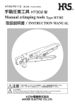
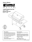
ATAD-P0106
初版 /First edition
手動圧着工具
Manual crimping tools
取扱説明書 / INSTRUCTION MANUAL
注意
CAUTION :
安全に使用していただくために使用前に、必ずこの取扱説明書をお読みください。
また、いつでもすぐに読めるように、この取扱説明書を保管してください。
Be sure to read this Instruction Manual carefully before using it to secure safe operation.
Save this Instruction Manual so that it is available whenever necessary.
安全にご使用していただくために
本 工 具 を 実 際 に ご 使 用 さ れ る オ ペ レ ー タ の 方 お よ び、 保 守、 修 理 等 を さ れ る 保 全 の 方 は、 以 下 の 安全についての注意事項 を熟読されて、怪我などされないようにご使用ください。
なお、本取扱説明書および、警告表示の内容を十分に理解し、指示を守ってください。
安全についての注意事項
基本的注意事項
注意
ご使用される前に本取扱説明書および、付属に入っている全ての説明書類を必ずお読みください。また、いつでも
すぐに読めるように、この取扱説明書を大切に保存してください。
安 全 装 置
本工具には、安全カバー等の安全装置は取り付いていません。圧着作業に際しては、ハンドル部に指等挟まないよ
う安全に十分配慮してご使用ください。
用 途
1. この工具は、本来の用途および本取扱説明書に規定された使用方法以外には使用しないでください。用途以外の
使用に対しては、当社は責任を負いません。
2. 工具には、改造等を加えないでください。改造によって起きた事故に対しては、当社は責任を負いません。
保 守
1. 不慣れによる事故を防ぐため、修理、調整は工具を熟知した保全技術者が本取扱説明書の指示範囲で行ってくだ
さい。不適切な修理・調整および非純正部品による事故に対しては、当社は責任を負いません。
2. 人身事故を防ぐため、修理調整・部品交換等の作業後は、ねじ・ナット等が緩んでいないことを確認してください。
3. 工具の使用期間中は、定期的に清掃を行ってください。
4. 事故を防ぐため、修理・調整した結果、正常に動かない場合は直ちに操作を中止し、当社に連絡し、修理依頼し
てください。
For safe operation
The operators of the tool and the maintenance personnel who are in charge of maintenance and repair work are required
to read the following SAFETY INSTRUCTIONS .
Fully understand and follow the descriptions given in this Instruction Manual and the warning symbols attached to the tool.
Safety instructions
CAUTION
Basic safety instructions
Be sure to read understand and follow all the instructions and other materials supplied with the tool before use. Save this
Instruction Manual and make it available, when necessary.
Safe operation
Be sure to use the tool as instructed so that your fingers nor part of clothing is caught in the tool during crimping operation.
Application
1. This tool shall only be used for its originally intended purpose while following the instructions specified in this Instruction
Manual. Hirose assumes no responsibility for any misuse of the tool other than the intended use.
2. Modifications to this tool is prohibited. We assume no responsibility for accidents resulting from modifications.
Maintenance
1. To prevent possible accidents caused by unfamiliarity with the operation of the tool, repair and adjustment of the tool shall
be conducted only by fully trained maintenance personnel. Any repair and adjustment beyond the range covered by the
instructions given in this Instruction Manual is prohibited. We assume no responsibility for accidents caused by improper
repair or adjustment or the use of non-genuine part(s).
2. To protect against personal injury, assure that screws and nuts are properly tightened after the completion of repair/
adjustment works or replacement of the parts.
3. Periodical cleaning of the tool is recommended.
4. In the event that your tool fails to perform satisfactory after repair or adjusting immediately stop the work and contact HRS
for service.
はじめに / Forward
この度は、手動圧着工具をご購入いただき誠にありがとうございます。
ご使用前に必ず本書をよくお読みいただき十分ご理解の上、正しくご使用くださいますようお願い致します。
Thank you for purchase of our manual crimping tool.
For safe operation read, understand and follow this Instruction Manual.
目 次
1. 工具使用上の注意及び保守.......................... 1
2-7-1. ランス高さの確認........................................7
2-7-2. 組立手順(例)
.............................................7
2-7-3. ハウジング組立状態の確認........................7
2. 圧着作業基本要領......................................... 2
2-1. 圧着端子各部の名称及び機能......................... 2
2-1-1. 圧着端子各部名称........................................2
2-7-4. 端子の引き抜き方法....................................7
2-7-5. 組立後の確認...............................................7
2-1-2. 圧着端子各部の機能....................................2
2-8. その他、注意事項............................................ 8
2-2. 電線被覆のストリップ.................................... 3
2-8-1. 電線結束時の注意事項................................8
2-2-1. ストリップ長さの適否................................3
2-2-2. 電線ストリップ状態...................................3
2-8-2. 導通耐圧チェック........................................8
2-8-3. 端子の取り扱い...........................................8
2-3. ベルマウス........................................................ 3
2-4. クリンプハイト............................................... 3
3. 工具の外観及び各部の名称......................... 9
2-5. 圧着部の引っ張り強度及び測定方法............. 4
4. 工具一覧表................................................. 10
2-5-1. 圧着部引っ張り強度....................................4
5. 作業手順..................................................... 11
2-5-2. 引っ張り強度の試験方法............................4
6. 圧着条件及び圧着品質基準 .......................12
2-6. 圧着後の端子形状の確認................................ 4
7. クリンプハイト調整方法........................... 13
2-6-1. 良品の基準...................................................4
2-6-2. 圧着不良例...................................................5
8. 圧着条件及び圧着品質基準表.................. 14
2-7. 端子のハウジングへの挿入............................ 7
CONTENTS
2-7-1. Checking the lance height................................ 7
1.Precautions in handling the tool and
maintenance......................................................1
2. Basic outline of crimp operation....................2
2-7-2. Assembling procedure (example).................... 7
2-7-3. Checking the assembly condition of the
housing.............................................................. 7
2-1. Configuration and function of crimp contact . 2
2-7-4. Contact extraction............................................. 7
2-1-1. Configuration of crimp contact........................ 2
2-7-5. Verification of the complete contact insertion.... 7
2-1-2. Function of each part of crimping contact..... 2
2-8. Other precautions............................................... 8
2-2. Stripping of wire outer insulation...................... 3
2-8-1. Precautions when tying the wire...................... 8
2-2-1. Correct stripping length................................... 3
2-8-2. Connector continuity check............................. 8
2-2-2. Stripped wire condition.................................... 3
2-8-3. Handling of the contacts................................... 8
2-3. Bellmouth (flare)................................................. 3
2-4. Crimp height........................................................ 3
3. Configuration of the tool.................................9
2-5. Tensile strength of crimped section and
measuring method............................................... 4
4. Table of tools...................................................10
2-5-2. Testing method of tensile strength................... 4
6.Crimping conditions and crimping quality
standard..........................................................12
7.Configuration of crimping............................13
5. Operating procedures.................................... 11
2-5-1. Tensile strength of crimped section................. 4
2-6. Confirmation of the shape of contact after
crimping............................................................... 4
2-6-1. Standards for acceptable crimp....................... 4
8. Table of crimping conditions and crimping
quality standard.............................................14
2-6-2. Example of defective crimping........................ 5
2-7. Insertion of contact into housing....................... 7
ii
1.工具使用上の注意及び保守 /Precautions in handling the tool and maintenance
■ 使用上の注意
1 手動圧着工具は、クリンプハイトの微調整が行なえま
せんので、端子の適合電線範囲であっても、ご使用に
なる電線が指定電線と異なる場合は工具に適合しない
ドライバー /
場合があります。
Flat blade
2 本書に示す適合端子、適合ケーブル以外の物を絶対圧
screwdriver
図1
着しないでください。
工具を叩いたり、高い所から落とす等の衝撃は絶対加えないでください。
工具には適正な加圧が行なわれるまでハンドルが開かないようにラチェット機構が備わっています。
ラチェットが解除する前にハンドルを開くことはできません。無理に開いたりすると工具が故障しますので絶対し
ないでください。
ラチェットが解除した後もハンドルに過度な荷重をかけ続けますと、ハンドルが閉じたまま開かなくなることがあ
ります。その際は、図 1 のようにドライバー等をハンドルに入れ開いてください。
また、過度な荷重をかけることはハンドツールのガタを引き起こし、正常な圧力が得られなくなる原因になります
のでご注意ください。
作業を始める時は、圧着した端子の圧着状態が良品の範囲になっているか確認を行なってください。
工具 /Tool
3
4
5
6
■ Handling precautions
1 The tools can not be adjusted for crimp height or configuration. Only specified wire size, construction and type must be used
with the applicable contact and tool.
2 Do not crimp other than the specified contact or wire.
3 Do not subject the tool to physical impact or drop.
4 Do not attempt to release the moveable handle before completing full compression as this may damage the tool. Handle will release after completion of the full compression. The handle can not be opened before automatic release of the ratchet.
5 Do not apply excessive compression on the handles after full compression. Occasionally the moveable handle may remain closed
after the full compression. Insert a flat blade screwdriver (or similar tool) as shown on illustration above, to release it.
In addition, applying an excessive compression can produce a play in the hand tool. With the hand tool with a play, the normal
pressure cannot be obtained. So, be careful.
6 Assure that the crimp condition after the termination with the wire is within specification.
■ 保守と点検
【日常のお手入れについて】
1 作業が終了した場合は、汚れ、異物等を柔らかい布で拭き取りハンドルを閉じクリンパ、アンビルの中に異物
が入り込まないようにして、乾燥した場所に保管してください。
2 ハンドル開閉の際、アンビルが、カジリ等無く滑らかに摺動する事を確認してください。
【定期メンテナンスについて】
弊社では、ご使用中の工具が適正な状態にあるか判断を行なうメンテナンスを行なっています。
メンテナンスをご希望される際は、弊社営業所または購入された代理店にご依頼ください。
【工具の修理について】
工具に不具合が生じ修理を希望される時は、解体などせずそのままの状態で、不具合内容を明示の上、弊社営業所
または代理店へお申し付けください。
不具合の内容によっては修理しかねる場合もありますので、予めご承知おきください。
■ Maintenance and inspection
【Routine maintenance】
1 Upon completion of work wipe the tool with a soft cloth to remove any stains or foreign particles, specially in the crimper
and anvil areas.
2 Close the handles making sure that the crimper and anvil slide smooth, without any interference. Store in the dry place.
【Routine maintenance】
HRS offers maintenance service to evaluate condition and performance of the tool.
Request this service from the place of purchase or the nearest HRS representative.
【Repair of the tools】
Contact the place of purchase or nearest HRS representative. Describe exact nature of the problem. Do not diss-assembly the
tool. If instructed, ship the tool in a secure package, with a written description of the problem.
HRS does not sell individual components for the tools.
Depending on it’s condition in some cases the tool may NOT be repairable.
−
−
2.圧着作業基本要領 / Basic outline of crimp operation
圧着作業の基本的な一般事項について説明します。
General description of the crimp process.
2-1.圧着端子各部の名称及び機能 /Configuration and function of crimp contact
2-1-1. 圧着端子各部名称 /Configuration of crimp contact
コンタクト部分 /Contact section
ベルマウス /
Bellmouth
セレーション /
Serrations
芯線 /
Conductor
被覆 /
Outer insulation
ワイヤーバレル /
Wire barrel
インシュレーションバレル /
Insulation barrel
ランス / Lance (retention tab)
2-1-2. 圧着端子各部の機能 /Function of each part of crimping contact
1 ワイヤーバレル(芯線圧着部).... U字形状で機械的な力により導線を加締め保持して端子と接続する役目を持ちます。
ワイヤーバレルの大きさにより適合する電線の範囲が決められます。
適合外の電線を圧着すると所定の性能が得られず品質上重大な事故を起こす事があります。
2 インシュレーションバレル .... 電線の被覆を加締めるバレルで、電線に負荷がかかった際にワイヤーバレル部で導線
が断線しないように電線を保持する機能を持ちます。
3 ランス ...................................... 端子をハウジング(絶縁ケース)に挿入した際端子をハウジングから抜けないように
固定するロック機構の役目をします。
ランスが変形していますと、ハウジングに挿入した後ロック機構が機能せず、端子が
ハウジングから抜けてしまったり所定の固定力が得られない事があります。
4 ベルマウス .............................. バレル端面での断線の防止と圧着部の引っ張り強度の安定を目的として設けている物です。
5 セレーション .......................... ワイヤーバレルの内面に平目や綾目の凹みを設ける事が有り、これをセレーションと
呼びます。
セレーションは圧着時にバレル面と導線の酸化皮膜の破壊を助長し、より電気的、機
械的に接続の安定を狙うものです。
6 コンタクト部 .......................... コネクタの雄と雌を嵌合させた時、相手側のコンタクトと電気的に接合する部分です。
1 Wire barrel .................. U-shaped section of the contact which is compressed around the conductors with a mechanical force. (conductor crimp section) Configuration and dimensions after the completion are critical for maintaining mechanical and electrical performance of the contact.
2 Insulation barrel............. U-shaped section of the contact which is compressed around the outer insulation of the wire. Its function is to act as a strain relief, preventing transmission of any pull force on the wire to the conductor
crimp section.
3 Lance............................ Retains the contact in the applicable insulator (socket). Any deformation of the lance may prevent retention or extraction of the terminated wire from the insulator body (socket).
(contact retention tab)
Note : Some contacts may NOT have lance and be retained in their respective housings by other means.
4 Bellmouth (flare).......... Critical configuration of the crimp section of the contact whose function is to avoid breakage of the terminated conductor and assure strength of the crimp.
5 Serrations...................... Deformations or cross-serrations of the material inside the wire barrel whose function is to break possible oxidation films on the contact and conductors during the crimping, thus assuring stable electrical
connection.
6 Contact section............ Configuration of the contact which will make electrical and mechanical connection with the corresponding mating contact.
−
−
2-2.電線被覆のストリップ / Stripping of wire outer insulation
2-2-1. ストリップ長さの適否���
�������������
/ Correct stripping length
電線のストリップ長さは、端子ごとに設定されています。ストリップ長さの加工精度により圧着の作業性品質が左
右されますので注意してください。
Stripping length of the wire is specified for each contact. Correct crimping depends on accurate stripping of the wire.
適正なストリップ長さ:圧着した際、ワイヤーバレル先端
から芯線が突き出しており、また被覆がインシュレーショ
ンバレルより引っ込んでいたりシールドバレル内に入り込
んだりしていない状態であること。
Correct stripping length: After crimping the conductors should
protrude from the top end of the Wire barrel and the Insulation
barrel should be around the Outer insulation, as shown on the
illustration on the left. Before crimping do not pull on the outer
insulation or attempt to insert it in the Wire barrel.
芯線突き出し /
Conductor juts out
2-2-2. 電線ストリップ状態
�����������
��/ Stripped wire condition
根元に傷をつけない /
Do not damage any individual strands
No
Yes
被覆切断端面 /
Incorrect stripping
a:ストリップ長さ
a : Stripping length
芯線の長さ /
Length of the strand
a
1 芯線に傷が無いこと。また一部が断
線したり脱落していないこと。
芯線の長さ、被覆切断端面がバラつい
2
ていたり、バラけていたりしないこと。
1 Conductor should be free from any damage or partially broken or missing strands.
2 The conductor and outer insulation cutoff’s must be straight. The outer insulation
can not be loose.
2-3. ベルマウス / Bellmouth (flare)
圧着を行った端子は、後部にベルマウスがあることを確認してください。
ベルマウスの大きさは、端子により異なります。ベルマウスが無い
と、ワイヤーバレル端面での芯線の断線や、圧着部の引っ張り強度
不足となる恐れがあります。ベルマウスが大き過ぎる時は、電気的
接続が不安定となったり、圧着部の引っ張り強度不足となる恐れが
あります。
Bellmouth must be present at the rear of the conductor crimped section and must be within the specified dimensions.
Size of it varies with each contact style. Absence of the bellmouth may cause conductor breakage and will affect the tensile
strength of the crimp. Excessive bellmouth may indicate insufficient tensile strength of the crimped section of the contact and affect the electric connection.
後部ベルマウス / Bellmouth
2-4. クリンプハイト / Crimp height
クリンプハイトは、圧着端子の圧着品質を決める重要な要因です。
クリンプハイトが規格から外れている場合は、品質上の重大な事故を起こす恐れがあります。手動圧着工具の場合、
端子の適合電線範囲内であっても、工具にはご使用になる電線が適合しない場合がありますのでご注意ください。
Crimp height is critical factor in determining the correct crimp condition and must be as specified.
Specified wire size, construction and style must be used. The crimp height requirement may not be applicable with some wires
although they may be within the specified dimensions.
* クリンプハイトの測定には、クリンプハイト測定用マイクロメーターをご使用ください。
* Use the micrometer for measuring the crimp height.
クリンプハイト ( 被覆 ) /
Crimp height (outer insulation)
クリンプハイト ( 芯線 ) /
Crimp height (conductor)
マイクロメーター ( アンビル )/
Micrometer (anvil)
マイクロメーター ( スピンドル )
バレルのほぼ中央で測る /
Micrometer (spindle) Measure
near the center of the barrel.
−
−
2-5. 圧着部の引っ張り強度及び測定方法 /
Tensile strength of crimped section and measuring method
2-5-1.����������
圧着部引っ張り強度 /�Tensile strength of crimped section
芯線圧着部(ワイヤーバレル部)の電線を引っ張った時に耐えられる強さのことで、端子ごと、電線ごとに許容値
を設定しています。
Retention strength of the crimped wire when the pull force (N) is applied to it. The pull force is defined for each style of the contact.
2-5-2.������������
引っ張り強度の試験方法 / Testing method of tensile strength
インシュレーションバレルが機能しないように、電線を長めにストラップしたものを圧着し、引っ張り試験機に取
りつけ、電線が破断した時の値を測定します。
(電線の引っ張り速度は 20 mm ~ 80 mm/ 分に設定してください。)
Secure the crimped contact on applicable fixture assuring that the wire can be freely pulled and the force can be measured.
Apply pull at the rate of 20 to 80 mm per minute until the failure of the crimp section (wire pulled-out). The value of the pull-out
force must be higher than the minimum specified.
2-6.圧着後の端子形状の確認 /Confirmation of the shape of contact after crimping
2-6-1. 良品の基準 /Standards for acceptable crimp
* 規格値については「8. 圧着条件及び圧着品質基準表」を参照のこと。
* See " 8. Table of crimping conditions and crimping quality standard" for the specified values.
1 クリンプハイトが規格内にあること。
2 ベルマウスが適正な大きさであること。 3
4
5
6
7
8
9
!0
!1
芯線の突き出しは適正であること。
ワイヤーバレルに被覆の食い込み(深打ち)となっていないこと。
被覆はインシュレーションバレルに適正に圧着されていること。
芯線がワイヤーバレルからはみ出していないこと。
端子のコンタクト部に変形がないこと。
ランスに変形がないこと。
ワイヤーバレル部に大きなバリが無いこと。
圧着部に亀裂やバレル外面の肌に荒れが無いこと。
端子の曲りが「8. 圧着条件及び圧着品質基準表」の規格を満足していること 1 The crimp height is in the specified range.
2 The bellmouth has an is correct size.
3 The protrusion of the conductor is correct.
4 The outer insulation is inserted in the conductor barrel.
5 The outer insulation is correct crimped in the insulation barrel.
6 The conductor does not protrude from the wire barrel.
7 The contact section of the contact is not deformed.
8 The lance is not deformed.
9 The wire barrel has no noticeable burr.
!0 The finished crimped section is free from any material crack or rough surface on the outside of the barrel.
!1 The bend angle in the contact is as specified in " 8. Table of crimping conditions and crimping quality standard".
7 端子コンタクト部 /
2 ベルマウス / Bellmouth
Contact section of contact
3 芯線位置 /
45 被覆位置 / Position of outer insulation
Protrusion of conductor
⑧ランス / Lance
1 芯線部クリンプハイト /
Contact conductor section
��������
of ������������
crimp height
1 被覆部クリンプハイト /
�������������������������
Outer insulation section
��������
of ������������
crimp height
!0 肌荒れ / Rough surface
−
−
9 バリ /
Burr
2-6-2. 圧着不良例 / Example of defective crimping
1 ベルマウス無し、過大 / None or excessive bellmouth
ベルマウス過大 /
Excessive bellmouth.
ベルマウス無し /
No bellmouth.
工具の調整状態や、工具への端子のセットの仕方により発生する事が
有ります。ベルマウスが無かったり大き過ぎる事により、芯線の断線
や引っ張り強度の不足、電気的接続の不安定となる恐れがあります。
Caused by incorrect positioning of the contact in the crimping section of the
tool. Can cause conductor break, low pull-out force or electrical connection
failure.
2 深打ち / Insulation bulge or protrusion
芯線が見えない / Conductor is invisible.
電線のストリップ寸法が不適切な時や、工具への電線のセットの仕方
により発生する事があります。
深打ちにより芯線の断線となる恐れがあります。
Caused by incorrect stripping of the wire or it’s positioning in the crimping
section of the tool. Conductor can be broken.
3 芯線の挿入不足 / Partial insertion of the conductor
芯線が見えない /Conductor is invisible.
電線のストリップ寸法が不適切な時に発生する事があります。
芯線の挿入不足により引っ張り強度の不足や、電気的接続の不安定と
なる恐れがあります。
Caused by incorrect wire stripping. Can cause conductor break, low pull-out
force or electrical connection failure.
4 浅打ち / Insufficient compression of the crimp sections
被覆が見えない /Outer insulation is not visible.
電線のストリップ寸法が不適切な時や、工具への電線のセットの仕方
により発生する事があります。
浅打ちにより芯線への負荷が直接に芯線圧着部に伝わり断線となる恐
れがあります。
Caused by incorrect wire stripping. Can cause conductor break, low pull-out
force or electrical connection failure.
5 芯線の突き出しが長過ぎる / Too long protrusion of the conductor.
電線のストリップ寸法が不適切な時や、工具への電線のセットの仕方
芯線が長すぎる /Too long
により発生する事があります。
突き出しが長過ぎる事によりコンタクトの接触障害となったりハウ
ジングへの挿入不完全となる恐れがあります。
Caused by incorrect stripping of the wire or it’s positioning in the crimping section of the tool. Can cause failure of the connection or interfere with the insertion of the terminated contact in the corresponding insulator (socket).
6 芯線はみ出し / Loose strands of the conductor.
芯線はみ出し /Loose
芯線がバラけたままの電線を使用すると発生する事があります。
芯線のはみ出しにより電気的接続の不安定となったり、引っ張り強度
の不足となる恐れがあります。
Caused by the loose conductor in the wire.
Can cause erratic electrical connection and loss of wire retention in the
crimp sections of the contact.
7 端子変形(ベントアップ、ダウン)/ Deformed contact (Bent UP/DOWN)
アップ / UP
ダウン / DOWN
工具の調整状態や摩耗、端子の工具へのセット状態、端子の取り扱
いにより発生する事があります。ベントアップ、ダウンが著しいと、
ハウジングへの挿入が行えない事があります。
Can be caused by the wear of the tool, positioning of the contacts in the
crimping sections of the tool or handling of the contact.
Excessive angle will prevent insertion of the contact in the corresponding
insulator (housing).
−
−
8 端子変形(ツイスト)/ Deformed contact (Twist)
工具の調整状態や、工具への端子のセット状態、端子の取り扱いに
より発生する事があります。ツイストが著しいと、ハウジングへの
ツイスト / Twist
挿入が行えない事があります。
Can be caused by the wear of the tool, positioning of the contacts in the
crimping sections of the tool or handling of the contact.
Excessive deformation of the contact will prevent insertion in the corresponding insulator (housing).
9 端子変形(ローリング)/ Deformed contact (Rolling)
グ/
リン
ロー ling
l
Ro
マイクロメーター
( スピンドル )/
Micrometer(spindle)
マイクロメーター
( アンビル )/
Micrometer(anvil)
工具の調整状態や歯型の摩耗、工具への端子のセット状態、端子の取
り扱いにより発生する事があります。ローリングが著しいと、ハウジ
ングへの挿入が行えない事があります。
Can be caused by the wear of the tool, positioning of the contacts in the
crimping sections of the tool or handling of the contact.
Excessive deformation of the contact will prevent insertion in the corresponding insulator (housing).
!0 インシュレーションバレルの変形(キックバック)/ Deformed insulation barrel (Kickback)
キックバック /Kickback
工具に適合しない電線を使用した時に発生する事があります。
キックバックが著しいと、ハウジングに挿入した後ハウジングから
端子が露出し、耐圧上の問題となる事があります。
Caused by the use of incorrect wire or contact.
Excessive protrusion may expose part of the contact after insertion in the
corresponding insulator (housing) and may cause electrical shorts.
!1 芯線圧着部アンビル痕の不均一 / Uneven anvil indentation
アンビル痕が不均一 /
Uneven anvil indentation
アンビルの摩耗などで発生する事があります。
アンビル痕が不均一ですと、電気的接触が不安定になること
があります。
Caused by the wear of the anvil side of the tool.
Can cause degradation of the electrical connection.
良品 /
Good
product
均一なアンビル痕 /
Even anvil indentation
!2 圧着面の傷、打痕 / Damage or nicks on the crimp’s outer surfaces.
クリンパに傷や摩耗が有る時、発生する事があります。
圧着面に傷や打痕がありますと、端子の変形やメッキはがれ等が発生
する事があります。
Caused by damage or wear of the crimp sections of the tool.
Can cause deformation of the contact, cracks or peels of the material.
キズ・打痕 / Damage or nick
!3 圧着バリの過大、左右不均一 / Too large or irregular crimping burr
バリ /Burr
工具の調整状態やクリンパ、アンビルの摩耗、傷がある時、発生する事があります。
バリが著しかったり著しく左右が不均一な事によりバリ部での端子の亀裂や、電気
的接続の不安定、強度不足、端子の変形となる恐れがあります。
Caused by damage or wear of the crimp sections of the tool.
Can cause deformation of the contact, cracks or peels of the material, degradation
of the electrical connection or loss of the wire retention.
−
−
2-7.端子のハウジングへの挿入 / Insertion of contact into housing
2-7-1.����������
ランス高さの確認 / Checking the lance height
ランス高さ /
Lance height
圧着した端子のランスの高さが所定の寸法内にあるか確認
してください。
Lance height must be as specified on applicable drawing.
2-7-2. 組立手順(例)/ Assembling procedure (example)
1) 端子より 10 cm 以内の電線の部分をつかみ挿入を
行ってください。
2) 端子は、ハウジングに対して水平となるように挿入し
てください。
3) 挿入中は端子を途中で止めず、ランスが掛かるまで
完全に行ってください。ランスが掛かった時は、「パ
チッ」という音と手応えがあります。
1) Hold the terminated wire within 10cm of the end of the
crimped contact.
2) Orient the contact lance as shown on illustration on the left
and align it with the housing.
3) Insert it until the lance is fully engaged, confirmed with an
audible sound.
10
cm
2-7-3. ハウジング組立状態の確認 / Checking the assembly condition of the housing
良 /Good
ランスがハウジングの角窓に引っ掛かっているもの。
端子が矢印方向に若干ガタがあり、浮遊性がある。
The lance is properly engaged in the rectangular opening in the housing.
The contact is moving in direction of the arrow (float), as illustrated.
挿入不足 / Inadequate insertion
挿入不足 ( 角窓からランス全体が見えない )。
Partial insertion. Lance is not engaged in the rectangular opening.
挿入不足 / Inadequate insertion
ランス変形 ( ランスが角窓に引っ掛かっていない )。
The lance was deformed and did not engage in the rectangular opening.
2-7-4. 端子の引き抜き方法 / Contact extraction
端子のハウジングからの引き抜き方法は、コネクタにより異なります。端子の抜き治具が専用で用意されているも
のもあります。詳細は、コネクタのカタログなどで確認を行ってください。
Contact extraction procedure varies with a specific connector insulator (housing).
Specific extraction tools are listed in applicable catalogs.
2-7-5. 組立後の確認 / Verification of the complete contact insertion
1) ハウジングに端子が正しく組込まれている事を確認し
てください。
2) 電線を軽く手で引っ張り端子が抜けない事を確認して
ください。
水平に引く /
Pull direction
1) Verify visually that the lance is fully engaged in the rectangular opening.
2) Apply slight pull force on the wire in the direction shown on the illustration and verify that the contact can not be pulled-out.
−
−
2-8.その他、注意事項 / Other precautions
�������������������������������
when tying the wire
2-8-1.����������
電線結束時の注意事項 / Precautions
電線を結束する際は、電線に余裕を持って行い、端子に直接負荷が掛からないように注意してください。
電線の両端を結束する際は、最初に結束した側の端子に負荷が掛からないように注意してください。
Tie at sufficient distance from the connector to assure that there are no forces applied to the inserted contacts.
2-8-2.����������
導通耐圧チェック /Connector continuity check
結線品の電気検査を行う際は、相手側コネクタなどに勘合した状態で行ってください。
端子接触部に異物を挿入したりしますとコンタクト部が変形し導通不良となる恐れがあります。
When performing this test make sure that the tied wires do not interfere with the mating with the corresponding part.
Do not insert any test probes or other pins into the socket contact as it may damage it, causing electric discontinuities.
2-8-3.�������
端子の取り扱い / Handling of the contacts
1
2
3
4
5
6
7
1
2
3
4
5
6
7
端子には必要以上に触れないでください。
端子に触れる際は、腐蝕防止の為なるべく手袋などを着用してください。
端子の上に物を置いたり、端子を落下しますと変形しますので乱暴な取り扱いはしないでください。
端子が絡んだ時は、無理に引っ張ったりせず、変形させないように慎重にほぐしてください。
端子をつまむ時は軽くつまみ、ランスやコンタクト部など変形しやすい所はつままないようにしてください。
圧着が完了した電線は、端子同士が絡まないように注意し、束ねたり重ねる場合は、端子に外力が掛からない
ように注意してください。
端子は腐蝕防止の為、ポリ袋などに入れて保管してください。
Do not handle the wires more than is necessary.
When touching the contacts wear appropriate gloves to avoid corrosion causing contamination.
Do not place any object on the contacts or drop it.
Avoid tangling of the terminated wires. Should the wires become tangled handle the contacts with extreme care to avoid any
deformation.
Do not handle contacts in the lance or contact areas. Any deformation in these areas will affect performance.
Do not entangle the contacts with each other.
Store the terminated wires in a non-corrosive environment.
−
−
15.6
3. 工具の外観及び各部の名称 /Configuration of the tool
ナット / Nut
製造番号表示 /
Serial number
HRS マーク表示 / HRS logo
ハイト調整用ストッパー /
Height adjustment stopper
可動ハンドル /
Moving handle
アンビル /
Anvil
42
(105)
クリンパ /
Crimper
製品名表示 /
Tool number
固定ハンドル /
Stationary handle
15.4
231
ハイト調整用ストッパー /
Height adjustment stopper
製造番号表示 /
Serial number
適合電線表示 /
Marking of applicable wire
42
(105)
適合電線切り替えツマミ /
Applicable wire changeover knob
製品名表示 /
Tool number
236
−
−
4.工具一覧表 / Table of tools
№
工具製品番号
Tool number
工具
HRS 製品コード
HRS tool No.
適合端子
Applicable contact
No.
適合端子
HRS 製品コード
Applicable HRS
contact No.
550-0029-0 HIF1-2226SC
550-0063-8 HIF3-2226SC
HIF3-2226SCA
3 PCN6-T2226HC 550-0012-7 PCN6-2226SC
4 HR12-SC-TC
150-0052-9 HR12-SC-111
HR12-SC-112
HR12-SC-113
HR10-PC-111
HR10-PC-112
5 RM-TC-11
150-0006-1 RM-PC-112
RM-SC-112
6 RM-TC-12
150-0007-4 RM-PC-122
RM-SC-122
7 T-1300C-111
250-0001-6 P-1300C-111
S-1300C-111
P-1300C-112
S-1300C-112
8 TC-1600-111
250-0003-1 PC-1600-111
SC-1600-111
PC-1600-112
SC-1600-112
9 TC-2100-111
250-0027-0 QR/P-XC-111
10 TC-2100-121
250-0028-2 QR/P-XC-121
11 TC-CD-111
250-0012-2 CD-PC-111
CD-SC-111
12 TC-CD-121
250-0013-5 CD-PC-121
CD-SC-121
13 TC-HNC-A
250-0005-7 HNC-2.5S-D-A
14 TC-HNC-B
250-0006-0 HNC-2.5S-D-B
560-0041-2
562-0079-8
562-0244-2
581-0176-2
112-0410-0
112-0411-3
112-0412-6
110-0515-6
110-0513-0
109-0668-7
109-0669-0
109-0672-4
109-0673-7
213-0685-3
213-0687-9
213-0686-6
213-0688-1
216-0331-0
216-0333-5
216-0332-2
216-0334-8
221-0009-2
221-0010-1
211-0185-8
211-0205-3
211-0202-5
211-0206-6
218-0037-5
218-0038-8
15
16
17
18
19
20
21
22
23
221-0102-8
221-0115-0
221-0103-0
221-0115-0
221-0104-3
221-0116-2
221-0105-6
221-0117-5
221-0182-7
221-0183-0
221-0184-2
221-0185-5
1 HIF1-T2226HC
2 HIF3-T2226HC
TC-QR/P1-PC1A
TC-QR/P1-PC1B
TC-QR/P1-PC2A
TC-QR/P1-PC2B
TC-QR/P1-SC1A
TC-QR/P1-SC1B
TC-QR/P1-SC2A
TC-QR/P1-SC2B
TC-QR/P8-111
24 TC-QR/P8-121
250-0015-0
250-0020-0
250-0016-3
250-0021-3
250-0017-6
250-0022-6
250-0018-9
250-0023-9
250-0030-4
QR/P1-PC1A-111
QR/P1-PC1B-121
QR/P1-PC2A-111
QR/P1-PC2B-121
QR/P1-SC1A-111
QR/P1-SC1B-121
QR/P1-SC2A-111
QR/P1-SC2B-121
QR/P8-PC-111
QR/P8-SC-111
250-0031-7 QR/P8-PC-121
QR/P8-SC-121
−
10 −
工具標準適合電線 / Standard applicable wire for tool
STYLE No. AWG No. 計算断面積 (mm2)
被覆外径
Sectional area (mm2) Outside diameter of
the outer insulation
UL 1007 22 ~ 26 0.342-0.141
φ 1.6 ~φ 1.3
UL 1007 22 ~ 26 0.342-0.141
φ 1.6 ~φ 1.3
UL 1007 22 ~ 26 0.342-0.141
UL1571 26 ~ 30 0.141-0.055
φ 1.6 ~φ 1.3
φ 0.98 ~
φ 0.7
UL 1007 20 ~ 24 0.534-0.221
φ 1.7 ~φ 1.4
UL 1007 24 ~ 28 0.221-0.089
φ 1.4 ~φ 1.2
UL 1007 20 ~ 26 0.534-0.141
φ 1.7 ~φ 1.3
UL 1007 24 ~ 28 0.221-0.089
φ 1.4 ~φ 1.2
UL 1015 14 ~ 16 2.175-1.348
UL 1007 18 ~ 24 0.865-0.221
UL 1007 20 ~ 24 0.534-0.221
φ 3.6 ~φ 3.2
φ 2.0 ~φ 1.4
φ 1.7 ~φ 1.4
UL 1007 24 ~ 28 0.221-0.089
φ 1.4 ~φ 1.2
UL 1007 22 ~ 26 0.342-0.141
UL 1007 26 ~ 30 0.141-0.055
0.865-0.221
2.175-1.348
0.221-0.089
0.534-0.221
0.865-0.221
2.175-1.348
0.221-0.089
0.534-0.221
0.221-0.089
φ 1.6 ~φ 1.3
φ 1.3 ~
φ 1.15
φ 2.0 ~φ 1.4
φ 3.6 ~φ 3.2
φ 1.4 ~φ 1.2
φ 1.7 ~φ 1.4
φ 2.0 ~φ 1.4
φ 3.6 ~φ 3.2
φ 1.4 ~φ 1.2
φ 1.7 ~φ 1.4
φ 1.4 ~φ 1.2
UL 1007 24 ~ 28 0.534-0.221
φ 1.7 ~φ 1.4
UL
UL
UL
UL
UL
UL
UL
UL
UL
1007
1015
1007
1007
1007
1015
1007
1007
1007
18 ~ 24
14 ~ 16
24 ~ 28
20 ~ 24
18 ~ 24
14 ~ 16
24 ~ 28
20 ~ 24
20 ~ 24
5. 作業手順 /Operating procedures
注意
操作中手への損傷防止のため、ハンドルの間や圧着部に指を入れないでください。
CAUTION
To prevent injury, do not place the fingers between the handles or crimping sections.
1) 工具の HRS マーク、製品名表示側を上に向けて持っ
てください。
2) ハンドルを最後まで握りラチェットを解除させ、ハン
ドルを最大に開いてください。
3) 適合電線切替ツマミがあるものは、切替ツマミを軽く
押し込みながら適合電線の表示が端子挿入側に来るよ
うにしてください。
4) 端子をアンビルの上に乗せ、端子ロケーターのストッパー
に突き当たる位置まで挿入してください。
(注意) 端子ストッパーはスプリングにより前後する機種が
あります。端子が端子ストッパーに密着し負荷が掛かっ
ていない位置がセット位置です。
5) 所定の長さに被覆をストリップしたケーブルの被覆端面を
芯線がほつれないように被覆ロケーターに突き当ててくだ
さい。
(注意) 端子を工具に挿入したり工具から取り出す際、ケー
ブルストッパーやアンビル等に端子を引っ掛けたり
して変形させないように注意してください。
端子ロケーター /
Contact locater
被覆クリンパ /
Insulation
crimper
ケーブルガイド /
Cable guide
芯線クリンパ /
Conductor
crimper
端子 /
Contact
1) Hold the tool with HRS logo and HRS tool number facing
up.
2) Compress the handle until the moving handle releases and
is fully open.
3) For the tool provided with the applicable wire changeover
knob, adjust so that the marking of the applicable wire is
brought to the contact insertion side while lightly pressing
the changeover knob.
4) Place the contact on the anvil. Insert the contact into the
contact locater until it comes in contact with the stop.
(Caution) Some tools may have contact stops held in place with
被覆アンビル /
芯線アンビル /
Outer insulation anvil Conductor anvil
the back spring. Insert the contact against it but do
not deflect the spring.
5) Strip the outer insulation of the cable to a specified length in prior. Press the end face of the outer insulation against the outer insulation locater taking care not to allow the conductors to ravel.
(Caution) When inserting the contact into the tool or taking it out from the tool be careful that the contact is not caught with the
cable stopper, anvil, etc., and is not deformed.
−
11 −
6.圧着条件及び圧着品質基準 /Crimping conditions and crimping quality standard
1) 本工具により圧着した端子のクリンプハイト及び引張り強度が「8. 圧着条件及び圧着品質基準表」の規格を満足し
ているかをご確認ください。
2) 本工具により圧着した端子の形状が良品の基準にある事をご確認ください。
( 注意 )1. 標準電線と異なる被覆径の電線をご使用の際は、弊社営業または代理店様にご相談ください。
2. 下図は端子形状の一例です。各部名称の参考にしてください。
1) Check to be sure that the contact that has been crimped using the tool satisfies the standerd described in “8.Table of crimping
conditions and crimping quality standard" with respect to the crimp height and the tensile strength.
2) Check to be sure that the contact that has been crimped using the tool is within the standard of good product with respect to the shape.
(Caution) 1. To use a wire a covering diameter of which is different from that of the standard wire, please contact our Business
Division or the distributor in your area.
2.The figure below is an example of the shape of contact. Use the figure for reference of configuration.
−
12 −
ベン
ト
Bent ダウン
DOW
/
N
被覆クリンプハイト /
Outer insulation crimp height
グ
ップ /
芯線クリンプハイト /
Conductor crimp height
/
電線ストリップ寸法 /
Strip dimension of wire
ベルマウス /
Bellmouth
被覆位置 /
Covering position
ア
ベント P
Bent U
ランス高さ /
Lance height (if applicable)
ツイスト /Twist
芯線先端位置 /
Protrusion of the
conductor
ロ
R ー
ol リ
lin ン
g
圧着バリ高さ /
Crimping burr height
7. クリンプハイト調整方法 / Adjusting the crimp height
圧着された端子のクリンプハイトが「8. 圧着条件及び圧
着品質基準表」の値を満足していない場合は、下記の方法
にてクリンプハイトを調整してください。
■ 規格値よりも高い場合
1) ハイト調整ストッパー下側のナットを緩めてくださ
い。
2) ハイト調整ストッパーを右側に回して高さが低くなる
ようにしてください。
3) ナットを締めてストッパーが動かないようにしてくだ
さい。
4) 再度端子を圧着して、クリンプハイトが規格内に入っ
ている事を確認してください。
ハイト調整ストッパー /
Height adjustment stopper
ナット / Nut
If the crimp height of the crimped contact does not satisfy the value given in "8. Crimping conditions and crimping quality standard,"
adjust the crimp height taking the procedure described below:
■ When the crimp height is larger than the specified value
1) Loosen the nut located underside of the height adjustment stopper.
2) Turn the height adjustment stopper clockwise to decrease the crimp height.
3) Turn the nut to secure the stop.
4) Re-crimp the contact to make sure that the crimp height falls within the specification.
ハイトが高くなる /
Crimp height increases
■
1) 2)
3)
4)
ハイトが低くなる /
Crimp height decreases
■ 規格値よりも低い場合
1) ハイト調整ストッパー下側のナットを緩めてくださ
い。
2) ハイト調整ストッパーを左側に回して高さが高くなる
ようにしてください。
3) ナットを締めてストッパーが動かないようにしてくだ
さい。
4) 再度端子を圧着して、クリンプハイトが規格内に入っ
ている事を確認してください。
When the crimp height is smaller than the specified value
Loosen the nut located underside of the height adjustment stopper.
Turn the height adjustment stopper counterclockwise to increase the crimp height.
Turn the nut to secure the stop.
Re-crimp the contact to make sure that the crimp height falls within the specification.
−
13 −
8. 圧着条件及び圧着品質基準表 /Table of crimping conditions and crimping quality standard
( 図中に指定の無い寸法の単位は mm) (Unit of the dimensions not specified in the table is mm.)
標準適合電線
電線
工具製品番号
適合端子
Standard
applicable wire
Applicable con- ストリップ寸法
Tool No.
Stripping
tact No.
STYLE No. A W G 芯線構成 被覆外径
dimension
Structure Outside diameNo.
of the
ter of the outer
of wire
conductor insulation
1
2
HIF1T2226HC
HIF3T2226HC
HIF1-2226SC
HIF3-2226SC
HIF3-2226SCA
UL1007
撚線
3.7 〜 4.1
Strandedwire
UL1007
撚線
3.7 〜 4.1
Strandedwire
−
14 −
3
PCN6T2226HC
PCN6-2226SC
HR12-SC-111
HR12-SC-112
4 HR12-SC-TC HR12-SC-113
HR10-PC-111
HR10-PC-112
5 RM-TC-11
6 RM-TC-12
RM-PC-112
RM-SC-112
RM-PC-122
RM-SC-122
UL1007
撚線
3.1 〜 3.5
Strandedwire
UL1571
撚線
1.5 〜 20
Strandedwire
UL1007
撚線
3.8 〜 4.2
Strandedwire
UL1007
撚線
3.8 〜 4.2
Strandedwire
22
17/0.16 φ 1.6
24
11/0.16 φ 1.5
26
7/0.16
22
17/0.16 φ 1.5
24
11/0.16 φ 1.4
26
7/0.16
22
17/0.16 φ 1.5
24
11/0.16 φ 1.4
26
7/0.16
φ 1.3
26
7/0.16
φ 0.98
28
7/0.127 φ 0.88
30
7/0.1
20
21/0.18 φ 1.7
22
17/0.16 φ 1.5
24
11/0.16 φ 1.4
24
11/0.16 φ 1.4
26
7/0.16
28
7/0.127 φ 1.2
φ 1.3
φ 1.3
φ 0.7
φ 1.3
クリンプハイト
Crimp height
引張強度
Pull
force
( 芯線 ) (被覆)(N ) 以上
(Con(Outer
(N) or
ductor) insula- more
tion)
0.75 〜
53
0.85
0.65 〜
35
0.75
0.60 〜
24
0.73
0.75 〜
53
0.85
0.65 〜
35
0.75
0.60 〜
24
0.73
1.10 〜
53
1.20
1.00 〜
35
1.10
0.95 〜
24
1.05
0.48 〜
24
0.54
0.44 〜
16
0.50
0.42 〜
9.8
0.46
0.80 〜
88
1.00
0.75 〜
49
1.00
0.75 〜
32
0.90
0.75 〜
32
0.90
0.65 〜
21
0.90
0.65 〜
14
0.77
圧着品質基準
Crimping quality standard
項目
Item
被覆位置
Outer
insulation
position
芯線先端 ベルマウス ベ ン ト
Bell
位置
アップ
Bent
Protrusion of mouth
UP
the conductor
ベ ン ト ツイスト ローリング ランス高さ 圧着バリ高さ
Rolling Lance Crimping
ダウン Twist
Bent
hight
burr hight
DOWN
寸法
(0.1 〜 (0.1 〜
Dimension 0.7)
0.5)
(0.2 〜
0.5)
3˚ 以内
With in 3˚
(4˚MAX) (8˚MAX)
2.4 〜
2.6
寸法
(0.1 〜 (0.1 〜
Dimension 0.7)
0.5)
(0.2 〜
0.5)
3˚ 以内
With in 3˚
(4˚MAX) (8˚MAX)
2.4 〜
2.6
寸法
(0.1 〜 (0.1 〜
Dimension 0.5)
0.5)
(0.1 〜
0.4)
3˚ 以内
With in 3˚
(5˚MAX) (5˚MAX)
(1.2)
0.3 以下
Less than
0.3
寸法
(0.2 〜 (0.2 〜
Dimension 0.5)
0.5)
(0.2 〜
0.5)
2˚ 以内
With in 2˚
(3˚MAX) (5˚MAX)
1.3 〜
1.5
0.3 以下
Less than
0.3
寸法
(0.2 〜 (0.2 〜
Dimension 0.5)
0.8)
(0.1 〜
0.5)
2˚ 以内
With in 2˚
(3˚MAX) (5˚MAX)
寸法
(0.2 〜 (0.2 〜
Dimension 0.5)
0.8)
(0.1 〜
0.5)
2˚ 以内
With in 2˚
(3˚MAX) (5˚MAX)
( 図中に指定の無い寸法の単位は mm) (Unit of the dimensions not specified in the table is mm.)
標準適合電線
電線
工具製品番号
適合端子
Standard applicable wire
ストリップ寸法
Applicable conTool No.
Stripping STYLE No. A W G 芯線構成 被覆外径
tact No.
dimension
Structure Outside diameNo.
of the
ter of the outer
of wire
conductor insulation
7 T-1300C-111
P-1300C-111
S-1300C-111
P-1300C-112
S-1300C-112
3.8 〜 4.2
UL1007
撚線
Strandedwire
−
15 −
PC-1600-111
SC-1600-111
8 TC-1600-111
PC-1600-112
SC-1600-112
UL1007
撚線
3.3 〜 3.7
Strandedwire
9 TC-2100-111 QR/P-XC-111
UL1007
撚線
3.5 〜 4.0
Strandedwire
10 TC-2100-121 QR/P-XC-121
11 TC-CD-111
12 TC-CD-121
CD-PC-111
CD-SC-111
CD-PC-121
CD-SC-121
UL1007
撚線
3.5 〜 4.0
Strandedwire
UL1007
撚線
3.5 〜 4.0
Strandedwire
UL1007
撚線
3.5 〜 4.0
Strandedwire
20
21/0.18 φ 1.7
22
17/0.16 φ 1.5
24
11/0.16 φ 1.4
26
7/0.16
24
11/0.16 φ 1.4
26
7/0.16
28
7/0.127 φ 1.2
14
41/0.26 φ 3.6
φ 1.3
φ 1.3
16
53/0.18 φ 3.2
18
42/0.16 φ 2.0
20
21/0.18 φ 1.7
22
17/0.16 φ 1.5
24
11/0.16 φ 1.4
20
21/0.18 φ 1.7
22
17/0.16 φ 1.5
24
11/0.16 φ 1.4
24
26
11/0.16 φ 1.4
7/0.16 φ 1.3
28
7/0.127 φ 1.2
クリンプハイト
Crimp height
引張強度
Pull
force
( 芯線 ) (被覆)(N ) 以上
(Con(Outer
(N) or
ductor) insula- more
tion)
0.85 〜
90
1.00
0.90 〜
54
0.80
0.88 〜
36
0.78
0.85 〜
24
0.75
0.85 〜
36
0.95
0.80 〜
24
0.90
0.75 〜
16
0.85
1.30 〜
147
1.40
1.15 〜
147
1.25
1.27 〜
127
1.35
1.16 〜
88
1.24
1.08 〜
53
1.24
1.08 〜
35
1.16
0.80 〜
88
1.00
0.75 〜
53
1.00
0.75 〜
36
0.90
36
0.69 〜
0.75
24
0.66 〜
16
0.72
圧着品質基準
Crimping quality standard
項目
Item
被覆位置
Outer
insulation
position
芯線先端 ベルマウス ベ ン ト
Bell
位置
アップ
Bent
Protrusion of mouth
UP
the conductor
ベ ン ト ツイスト ローリング ランス高さ 圧着バリ高さ
Rolling Lance Crimping
ダウン Twist
Bent
hight
burr hight
DOWN
寸法
Dimension
3.1 〜
3.3
0.3 以下
Less than
0.3
寸法
(0.2 〜 (0.3 〜
Dimension 0.5)
0.8)
(0.2 〜
0.5)
2˚ 以内
With in 2˚
(2˚MAX) (2˚MAX)
寸法
(0.2 〜 (0.1 〜
Dimension 1.0)
1.0)
(0.2 〜
0.5)
5˚ 以内
With in 5˚
(5˚MAX)
(10˚
MAX)
1.2 〜
1.6
0.1 以下
Less than
0.1
寸法
(0.2 〜 (0.1 〜
Dimension 1.0)
1.0)
(0.2 〜
0.5)
5˚ 以内
With in 5˚
(5˚MAX)
(10˚
MAX)
1.2 〜
1.6
0.1 以下
Less than
0.1
寸法
Dimension
※
(0.4 〜
0.8)
(0.2 〜
0.5)
2˚ 以内
With in 2˚
(2˚MAX) (2˚MAX)
0.1 〜
0.3
寸法
Dimension
※
(0.4 〜
0.8)
(0.2 〜
0.5)
2˚ 以内
With in 2˚
(2˚MAX) (2˚MAX)
0.1 〜
0.3
※ワイヤーバレルとインシュレーションバレルの間に位置すること /It should be located between the wire barrel and insulation barrel.
( 図中に指定の無い寸法の単位は mm) (Unit of the dimensions not specified in the table is mm.)
標準適合電線
工具製品番号 適合端子製造番号 電線
Standard applicable wire
ストリップ寸法
Tool product Applicable conNo.
tact product No. Stripping STYLE No. A W G 芯線構成 被覆外径
dimension
Structure Outside diameNo.
of the
ter of the outer
of wire
conductor insulation
13 TC-HNC-A
14 TC-HNC-B
−
16 −
15
TC-QR/P1PC1A
TC-QR/P116
PC1B
17
18
TC-QR/P1PC2A
TC-QR/P1PC2B
HNC-2.5S-D-A
HNC-2.5S-D-B
QR/P1PC1A-111
UL1007
撚線
2.8 〜 3.3
Strandedwire
UL1007
撚線
2.8 〜 3.3
Strandedwire
3.9 〜 4.3
UL1007
撚線
Strandedwire
QR/P1PC1B-111
UL1015
撚線
3.9 〜 4.3
Strandedwire
QR/P1PC2A-111
UL1007
撚線
3.6 〜 4.0
Strandedwire
QR/P1PC2B-111
UL1007
撚線
3.6 〜 4.0
Strandedwire
22
17/0.16 φ 1.6
24
11/0.16 φ 1.5
26
7/0.16
φ 1.3
26
7/0.16
φ 1.3
28
φ 1.2
7/0.127
30
φ 1.15
18
42/0.16 φ 2.0
20
21/0.18 φ 1.7
22
17/0.16 φ 1.5
24
11/0.16 φ 1.4
14
41/0.26 φ 3.6
16
53/0.18 φ 3.2
24
11/0.16 φ 1.4
26
7/0.16
28
7/0.127 φ 1.2
20
21/0.18 φ 1.7
22
17/0.16 φ 1.5
24
11/0.16 φ 1.4
φ 1.3
クリンプハイト
Crimp height
引張強度
Pull
force
( 芯線 ) (被覆)(N ) 以上
(Con(Outer
(N) or
ductor) insula- more
tion)
0.83 〜
53
0.93
0.82 〜
35
0.92
0.80 〜
24
0.90
0.68 〜
24
0.78
0.66 〜
16
0.76
0.65 〜
9.8
0.75
1.02 〜
128
1.16
0.94 〜
88
1.08
0.84 〜
53
0.92
0.82 〜
36
0.90
1.36 〜
147
1.48
1.27 〜
147
1.37
0.71 〜
36
0.79
0.68 〜
24
0.76
0.67 〜
16
0.75
0.96 〜
88
1.04
0.88 〜
53
0.96
0.84 〜
36
0.92
圧着品質基準
Crimping quality standard
項目
Item
被覆位置
Outer
insulation
position
芯線先端 ベルマウス ベ ン ト
Bell
位置
アップ
Bent
Protrusion of mouth
UP
the conductor
ベ ン ト ツイスト ローリング ランス高さ 圧着バリ高さ
Rolling Lance Crimping
ダウン Twist
Bent
hight
burr hight
DOWN
寸法
(0.1 〜 (0.1 〜
Dimension 0.7)
0.4)
(0.2 〜
0.4)
3˚ 以内
With in 3˚
(3˚MAX) (5˚MAX)
0.1 以下
Less than
0.1
寸法
(0.1 〜 (0.1 〜
Dimension 0.7)
0.4)
(0.2 〜
0.4)
3˚ 以内
With in 3˚
(3˚MAX) (5˚MAX)
0.1 以下
Less than
0.1
寸法
(0.3 〜 (0.1 〜
Dimension 1.0)
1.0)
(0.2 〜
0.5)
3˚ 以内
With in 3˚
(3˚MAX) (8˚MAX)
寸法
(0.3 〜 (0.1 〜
Dimension 1.0)
1.0)
(0.2 〜
0.5)
3˚ 以内
With in 3˚
(3˚MAX)
(10˚
MAX)
寸法
(0.2 〜 (0.1 〜
Dimension 0.8)
0.8)
(0.2 〜
0.5)
3˚ 以内
With in 3˚
(3˚MAX)
(10˚
MAX)
寸法
(0.2 〜 (0.1 〜
Dimension 0.8)
0.8)
(0.2 〜
0.5)
3˚ 以内
With in 3˚
(3˚MAX)
(10˚
MAX)
標準適合電線
電線
工具製品番号
適合端子
Standard applicable wire
ストリップ寸法
Applicable conTool No.
Stripping STYLE No. A W G 芯線構成 被覆外径
tact No.
dimension
Structure Outside diameNo.
of the
ter of the outer
of wire
conductor insulation
TC-QR/P119
SC1A
TC-QR/P120
SC1B
21
−
TC-QR/P1SC2A
QR/P1SC1A-111
QR/P1SC1B-111
UL1015
撚線
3.9 〜 4.3
Strandedwire
QR/P1SC2A-111
UL1007
撚線
3.6 〜 4.0
Strandedwire
17 −
22
23
24
TC-QR/P1SC2B
TC-QR/
P8-111
TC-QR/
P8-121
UL1007
撚線
3.9 〜 4.3
Strandedwire
QR/P1SC2B-111
QR/P8-PC-111
QR/P8-SC-111
QR/P8-PC-121
QR/P8-SC-121
UL1007
撚線
3.6 〜 4.0
Strandedwire
UL1007
撚線
3.1 〜 3.5
Strandedwire
UL1007
撚線
3.1 〜 3.5
Strandedwire
18
42/0.16 φ 2.0
20
21/0.18 φ 1.7
22
17/0.16 φ 1.5
24
11/0.16 φ 1.4
14
41/0.26 φ 3.6
16
53/0.18 φ 3.2
24
11/0.16 φ 1.4
26
7/0.16
28
7/0.127 φ 1.2
20
21/0.18 φ 1.7
22
17/0.16 φ 1.5
24
11/0.16 φ 1.4
20
21/0.18 φ 1.7
22
17/0.16 φ 1.5
24
11/0.16 φ 1.4
24
11/0.16 φ 1.4
26
7/0.16
28
7/0.127 φ 1.2
φ 1.3
φ 1.3
クリンプハイト
Crimp height
引張強度
Pull
force
( 芯線 ) (被覆)(N ) 以上
(Con(Outer
(N) or
ductor) insula- more
tion)
1.02 〜
128
1.16
0.94 〜
88
1.08
0.84 〜
53
0.92
0.82 〜
36
0.90
1.36 〜
1.48
147
1.27 〜
1.37
0.71 〜
36
0.79
0.68 〜
24
0.76
0.67 〜
16
0.75
0.96 〜
88
1.04
0.88 〜
53
0.96
0.84 〜
36
0.92
1.00 〜
88
1.08
0.94 〜
53
1.02
0.88 〜
36
0.96
0.82 〜
36
0.88
0.76 〜
24
0.82
0.72 〜
16
0.78
圧着品質基準
Crimping quality standard
項目
Item
被覆位置
Outer
insulation
position
芯線先端 ベルマウス ベ ン ト
Bell
位置
アップ
Bent
Protrusion of mouth
UP
the conductor
ベ ン ト ツイスト ローリング ランス高さ 圧着バリ高さ
Rolling Lance Crimping
ダウン Twist
Bent
hight
burr hight
DOWN
寸法
(0.3 〜 (0.1 〜
Dimension 1.0)
1.0)
(0.2 〜
0.5)
3˚ 以内
With in 3˚
(3˚MAX)
(10˚
MAX)
寸法
(0.3 〜 (0.1 〜
Dimension 1.0)
1.0)
(0.2 〜
0.5)
3˚ 以内
With in 3˚
(3˚MAX)
(10˚
MAX)
寸法
(0.2 〜 (0.1 〜
Dimension 0.8)
0.8)
(0.2 〜
0.5)
3˚ 以内
With in 3˚
(3˚MAX)
(10˚
MAX)
寸法
(0.2 〜 (0.1 〜
Dimension 0.8)
0.8)
(0.2 〜
0.5)
3˚ 以内
With in 3˚
(3˚MAX)
(10˚
MAX)
寸法
(0.1 〜 (0.1 〜
Dimension 0.7)
0.7)
(0.2 〜
0.5)
3˚ 以内
With in 3˚
(3˚MAX) (8˚MAX)
1.8 〜
2.2
0.3 以下
Less than
0.3
寸法
(0.1 〜 (0.1 〜
Dimension 0.7)
0.7)
(0.2 〜
0.5)
3˚ 以内
With in 3˚
(3˚MAX) (8˚MAX)
1.8 〜
2.2
0.3 以下
Less than
0.3
取扱説明書番号
ATAD-P0106
発行年月
2009 年 5 月
改定年月
版 数
年 月
初
版
注意
(1)
(2)
(3)
本書の一部または全部を無断転載する事は固くお断り致します。
本書の内容について、将来予告なしに変更することがあります。
当社では、本製品の運用を理由とする損失、逸失利益などの請求につきましては、責任を負い兼ねま
すのでご了承ください。
(4)
本製品がお客様により不適切に使用されたり、本書の内容に従わずに取り扱われたり、またはヒロセ
(5)
電機株式会社以外の第三者により修理、変更された事などに起因して生じた損害などにつきましては、
責任を負い兼ねますのでご了承ください。
本製品仕様について、改良のため将来予告なしに変更することがあります。
2009
CAUTION
(1)
(2)
(3)
(4)
No part of this manual may be reproduced without the written permission of Hirose Electric Co., Ltd.
Descriptions in this manual are subject to change without notice.
We assume no liability to any claim for loss or failure to earn profit resulting from the use of the machine.
We assume no responsibility for any damage resulting from the improper use of the tools, including failure to
follow the instructions given in this Instruction Manual. This includes repair or modification conducted by
any third party other than Hirose Electric Co., Ltd.
(5) The specifications of the product are subject to change without notice.
2009
本社
��
�
〒 141-8587 東京都品川区大崎 5-5-23
本製品に関するお問い合わせは下記までご連絡下さい。
生産技術部 〒 222-8566 神奈川県横浜市港北区菊名 7-3-13
TEL:045(414)1406
FAX:045(402)7861
http://www.hirose.co.jp
本取扱説明書は、当社ホームページからダウンロードできます。
5-23, OSAKI 5-CHOME, SHINAGAWA-KU, TOKYO 141-8587, JAPAN
PHONE : 81-03-3491-9741 FAX: 81-03-3193-2933
http://www.hirose.com
09 • 05 Printed in Japan